

PHILIPS 7603 Service Manual

IMPORTANT SAFETY NOTICE
Proper service and repair is important to the safe, reliable operation of all Philips
Consumer Electronics Company** Equipment. The service procedures recommended by
Philips and described in this service manual are effective methods of performing service
operations. Some of these service operations require the use of tools specially designed
for the purpose. The special tools should be used when and as recommended.
It is important to note that this manual contains various CAUTIONS and NOTICES
which should be carefully read in order to minimize the risk of personal injury to service
personnel. The possibility exists that improper service methods may damage the
equipment. It also is important to understand that these CAUTIONS and NOTICES
ARE NOT EXHAUSTIVE. Philips could not possibly know, evaluate and advise the
service trade of all conceivable ways in which service might be done, or of the possible
hazardous consequences of each way. Consequently, Philips has not undertaken any such
broad evaluation. Accordingly, a servicer who uses a service procedure or tool which is
not recommended by Philips must first satisfy himself thoroughly that neither his safety
nor the safe operation of the equipment will be jeopardized by the service method
selected.
** Hereafter throughout this manual, Philips Consumer Electronics Company will be
referred to as Philips.
WARNING
Critical components having special safety characteristics are identified with a or
"S" by the Ref. No. in the parts list and enclosed within a broken line* (where
several critical components are grouped in one area) along with the safety symbol
on the schematics or exploded views. Use of substitute replacement parts which
do not have the same specified safety characteristics may create shock, fire, or other
hazards. Under no circumstances should the original design be modified or altered
without written permission from Philips. Philips assumes no liability, express or
implied, arising out of any unauthorized modification of design. Servicer assumes all
liability.
* Broken Line ____ _ ____ _ ____ _ ____

FIRE AND SHOCK HAZARD
1. Be sure all components are positioned in such a way as to avoid the possibility of adjacent component
shorts. This is especially important on those chassis which are transported to and from the service shop.
2. Never release a repaired unit unless all protective devices such as insulators, barriers, covers, strain
reliefs, and other hardware have been installed in accordance with the original design.
3. Soldering and wiring must be inspected to locate possible cold solder joints, solder splashes, sharp solder
points, frayed leads, pinched leads, or damaged insulation (including the ac cord). Be certain to remove
loose solder balls and all other loose foreign particles.
4. Check across-the-line components and other components for physical evidence of damage or
deterioration and replace if necessary. Follow original layout, lead length, and dress.
5. No lead or component should touch a receiving tube or a resistor rated at 1 watt or more. Lead tension
around protruding metal surfaces or edges must be avoided.
6. Critical components having special safety characteristics are identified with an 'S' by the Ref. No. in the
parts list and enclosed within a broken line* (where several critical components are grouped in one area)
along with the safety symbol on the schematic diagrams and /or exploded views.
7. When servicing any unit, always use a separate isolation transformer for the chassis. Failure to use a
separate isolation transformer may expose you to possible shock hazard, and may cause damage to
servicing instruments.
8. Many electronic products use a polarized ac line cord (one wide pin on the plug). Defeating this safety
feature may create a potential hazard to the servicer and the user. Extension cords which do not
incorporate the polarizing feature should never be used.
9. After reassembly of the unit, always perform an ac leakage test or resistance test from the line cord to all
exposed metal parts of the cabinet. Also, check all metal control shafts (with knobs removed), antenna
terminals, handles, screws, etc., to be sure the unit may be safely operated without danger of electrical
shock.
* Broken line ____ _ ____ _ ____ _ ____

LEAKAGE CURRENT COLD CHECK
1. Unplug the ac line cord and connect a jumper between the two prongs of the plug.
2. Turn on the power switch.
3. Measure the resistance value between the jumpered ac plug and all exposed cabinet parts of the receiver,
such as screw heads, antennas, and control shafts. When the exposed metallic part has a return path to the
chassis, the reading should be between 1 megohm and 5.2 megohms. When the exposed metal does not
have a return path to the chassis, the reading must be infinity. Remove the jumper from the ac line cord.
LEAKAGE CURRENT HOT CHECK
1. Do not use an isolation transformer for this test. Plug the completely reassembled receiver directly into
the ac outlet.
2. Connect a 1.5k, 10W resistor paralleled by a 0.15uF. capacitor between each exposed metallic cabinet
part and a good earth ground such as a water pipe, as shown below.
3. Use an ac voltmeter with at least 5000 ohms/volt sensitivity to measure the potential across the resistor.
4. The potential at any point should not exceed 0.75 volts. A leakage current tester may be used to make
this test; leakage current must not exceed 0.5mA. If a measurement is outside of the specified limits,
there is a possibility of shock hazard. The receiver should be repaired and rechecked before returning it
to the customer.
5. Repeat the above procedure with the ac plug reversed. (Note: An ac adapter is necessary when a
polarized plug is used. Do not defeat the polarizing feature of the plug.)
OR
With the instrument completely reassembled, plug the ac line cord directly into a 120Vac outlet. (Do not
use an isolation transformer during this test.) Use a leakage current tester or a metering system that
complies with American National Standards Institute (ANSI) C101.1 Leakage Current for Appliances and
Underwriters Laboratories (UL) 1410, (50.7). With the instrument ac switch first in the on position and
then in the off position, measure from a known earth ground (metal water pipe, conduit, etc.) to all exposed
metal parts of the instrument (antennas, handle brackets, metal cabinet, screw heads, metallic overlays,
control shafts, etc.), especially any exposed metal parts that offer an electrical return path to the chassis.
Any current measured must not exceed 0.5mA. Reverse the instrument power cord plug in the outlet and
repeat the test. See the graphic below.


TV SAFETY NOTES
SAFETY CHECKS
After the original service problem has been corrected, a complete safety check should be made. Be sure to
check over the entire set, not just the areas where you have worked. Some previous servicer may have left
an unsafe condition, which could be unknowingly passed on to your customer. Be sure to check all of the
following:
Fire and Shock Hazard
Implosion
X-Radiation
Leakage Current Cold Check
Leakage Current Hot Check
Picture Tube Replacement
Parts Replacement
WARNING: Before removing the CRT anode cap, turn the unit OFF and short the HIGH VOLTAGE to
the CRT DAG ground.
SERVICE NOTE: The CRT DAG is not at chassis ground.
IMPLOSION
1. All picture tubes used in current model receivers are equipped with an integral implosion system.
Care should always be used, and safety glasses worn, whenever handling any picture tube. Avoid
scratching or otherwise damaging the picture tube during installation.
2. Use only replacement tubes specified by the manufacturer.
X-RADIATION
1. Be sure procedures and instructions to all your service personnel cover the subject of X-radiation.
Potential sources of X-rays in TV receivers are the picture tube and the high voltage circuits. The
basic precaution which must be exercised is to keep the high voltage at the factory recommended
level.
2. To avoid possible exposure to X-radiation and electrical shock, only the manufacturer's specified
anode connectors must be used.
3. It is essential that the service technician has an accurate HV meter available at all times. The
calibration of this meter should be checked periodically against a reference standard.
4. When the HV circuitry is operating properly there is no possibility of an X-radiation problem. High
voltage should always be kept at the manufacturer's rated value - no higher - for optimum
performance. Every time a color set is serviced, the brightness should be run up and down while
monitoring the HV with a meter to be certain that the HV is regulated correctly and does not exceed
the specified value. We suggest that you and your technicians review test procedures so that HV and
HV regulation are always checked as a standard servicing procedure, and the reason for this prudent
routine is clearly understood by everyone. It is important to use an accurate and reliable HV meter. It
is recommended that the HV reading be recorded on each customer's invoice, which will
demonstrate a proper concern for the customer's safety.

5. When troubleshooting and making test measurements in a receiver with a problem of excessive high
voltage, reduce the line voltage by means of a Variac to bring the HV into acceptable limits while
troubleshooting. Do not operate the chassis longer than necessary to locate the cause of the excessive
HV.
6. New picture tubes are specifically designed to withstand higher operating voltages without creating
undesirable X-radiation. It is strongly recommended that any shop test fixture which is to be used
with the new higher voltage chassis be equipped with one of the new type tubes designed for this
service. Addition of a permanently connected HV meter to the shop test fixture is advisable. The
CRT types used in these new sets should never be replaced with any other types, as this may result in
excessive X-radiation.
7. It is essential to use the specified picture tube to avoid a possible X-radiation problem.
8. Most TV receivers contain some type of emergency "Hold Down" circuit to prevent HV from rising
to excessive levels in the presence of a failure mode. These various circuits should be understood by
all technicians servicing them, especially since many hold down circuits are inoperative as long as
the receiver performs normally.
PICTURE TUBE REPLACEMENT
The primary source of X-radiation in this television receiver is the picture tube. The picture tube
utilized in this chassis is specially constructed to limit X-radiation emissions. For continued Xradiation protection, the replacement tube must be the same type as the original, including suffix letter,
or a Philips approved type.
PARTS REPLACEMENT
Many electrical and mechanical parts in Philips television sets have special safety related
characteristics. These characteristics are often not evident from visual inspection nor can the protection
afforded by them necessarily be obtained by using replacement components rated for higher voltage,
wattage, etc. The use of a substitute part which does not have the same safety characteristics as the
Philips recommended replacement part shown in this service manual may create shock, fire, or other
hazards.
PRODUCT SAFETY GUIDELINES FOR ALL PRODUCTS
CAUTION: Do not modify any circuit. Service work should be performed only after you are thoroughly
familiar with all of the following safety checks. Risk of potential hazards and injury to the user increases if
safety checks are not adhered to.
USE A SEPARATE ISOLATION TRANSFORMER FOR THIS UNIT WHEN SERVICING.

PREVENTION OF ELECTROSTATIC DISCHARGE (ESD)
Some semiconductor solid state devices can be damaged easily by static electricity. Such components
commonly are called Electrostatically Sensitive (ES) Devices, Examples of typical ES devices are
integrated circuits and some field-effect transistors and semiconductor "chip" components. The following
techniques should be used to help reduce the incidence of component damage caused by electrostatic
discharge (ESD).
1. Immediately before handling any semiconductor component or semiconductor-equipped assembly, drain
off any ESD on your body by touching a known earth ground. Alternatively, obtain and wear a
commercially available discharging ESD wrist strap, which should be removed for potential shock
reasons prior to applying power to the unit under test.
2. After removing an electrical assembly equipped with ES devices, place the assembly on a conductive
surface such as aluminum foil, to prevent electrostatic charge buildup or exposure of the assembly.
3. Use only a grounded-tip soldering iron to solder or unsolder ES devices.
4. Use only an anti-static solder removal device. Some solder removal devices not classified as "antistatic
(ESD protected)" can generate an electrical charge sufficient to damage ES devices.
5. Do not use Freon propelled chemicals. These can generate electrical charges sufficient to damage ES
devices.
6. Do not remove a replacement ES device from its protective package until immediately before you are
ready to install it (most replacement ES devices are packaged with leads electrically shorted together by
conductive foam, aluminum foil or comparable conductive material).
7. Immediately before removing the protective material from the leads of a replacement ES device, touch
the protective material to the chassis or circuit assembly into which the device will be installed.
CAUTION: Be sure no power is applied to the chassis or circuit and observe all other safety precautions.
8. Minimize bodily motions when handling unpackaged replacement ES devices. (Otherwise harmless
motion such as the brushing together of your clothes fabric or the lifting of your feet from a carpeted
floor can generate static electricity (ESD) sufficient to damage an ES device.)
NOTE to CATV system Installer:
This reminder is provided to call the CATV system installer's attention to article 820-22 of the NEC that
provides guidelines for proper grounding and, in particular, specifies that the cable ground shall be
connected to the grounding system of the building, as close to the point of cable entry as practical.

PRACTICAL SERVICE PRECAUTIONS
IT MAKES SENSE TO AVOID EXPOSURE TO ELECTRICAL SHOCK. While some sources are
expected to have a possible dangerous impact, others of quite high potential are of limited current and are
sometimes held in less regard.
ALWAYS RESPECT VOLTAGES. While some may not be dangerous in themselves, they can cause
unexpected reactions – reactions that are best avoided. Before reaching into the powered color TV set, it is
best to test the high voltage insulation. It is easy to do, and is just a good service precaution.
BEFORE POWERING UP THE TV WITH THE BACK OFF (or on a test fixture), attach a clip lead to
the CRT DAG ground and to a screwdriver blade that has a well insulated handle. After the TV is powered
on and high voltage has developed, probe the anode lead with the blade, starting at the bottom of the High
Voltage Transformer (flyback – IFT). Move the blade to within two inches of the connector of the CRT. IF
THERE IS AN ARC, YOU FOUND IT THE EASY WAY, WITHOUT GETTING A SHOCK! If
there is an arc to the screwdriver blade, replace the High Voltage Transformer or the lead, (if removable)
whichever is causing the problem.
PICTURE TUBE REPLACEMENT PROCEDURE
Note: a. Two (2) people are required to handle this picture tube.
b. Safety Glasses must be worn during this procedure or whenever directly handling a picture tube.
c. Take care in each step not to damage the CRT or the cabinet.
1. Remove the Chassis and the CRT Socket Board Module from the cabinet.
2. A furniture pad or blanket should be positioned on the floor to support only the CRT Face. This pad or
blanket should be high enough to keep the CRT Face approximately 12 to 14 inches off the floor.
3. Using two people, place the cabinet in a front down position with the CRT Face on the pad or blanket.
4. Place padded blocks under each corner of the cabinet to keep it from rocking.
5. Remove the four screws, at the corners of the CRT.
6. With two people lowering the cabinet to the floor, leave the CRT elevated by the pad or blanket.
Note: Take care not to grasp the neck of the CRT during this procedure, as it is extremely fragile.
7. Two (2) people may then lift the CRT from the cabinet.
8. Remove the degaussing coil from the defective CRT and mount on the replacement. Take care to
maintain the exact shape and fit.
To install the new CRT, reverse steps 1 to 7.

Technical Specifications, Connections and Chassis Overview
Technical Specifications
Audio ratings
1 W mono
2 x 1 W non-DBX stereo (LC stereo)
2 x 3 W DBX stereo (with SAP)
Reception
Tuning system : PLL
Color systems : NTSC
Sound systems : FM-mono
: BTSC non-DBX
BTSC DBX
A/V connections : NTSC M
Channel selections : 181 channels, full cable
IF frequency : 45.75 MHz
Aerial input : 75 Ω, Coax
Miscellaneous
AC voltage : 90 - 140 V (±10 %)
AC frequency : 60 Hz (±5 %)
Ambient temperature : + 5 to + 45 deg. C
Maximum humidity : 90 %
Power consumption : 36 W (14")
100 W (32")
Standby Power consumption : < 3 W
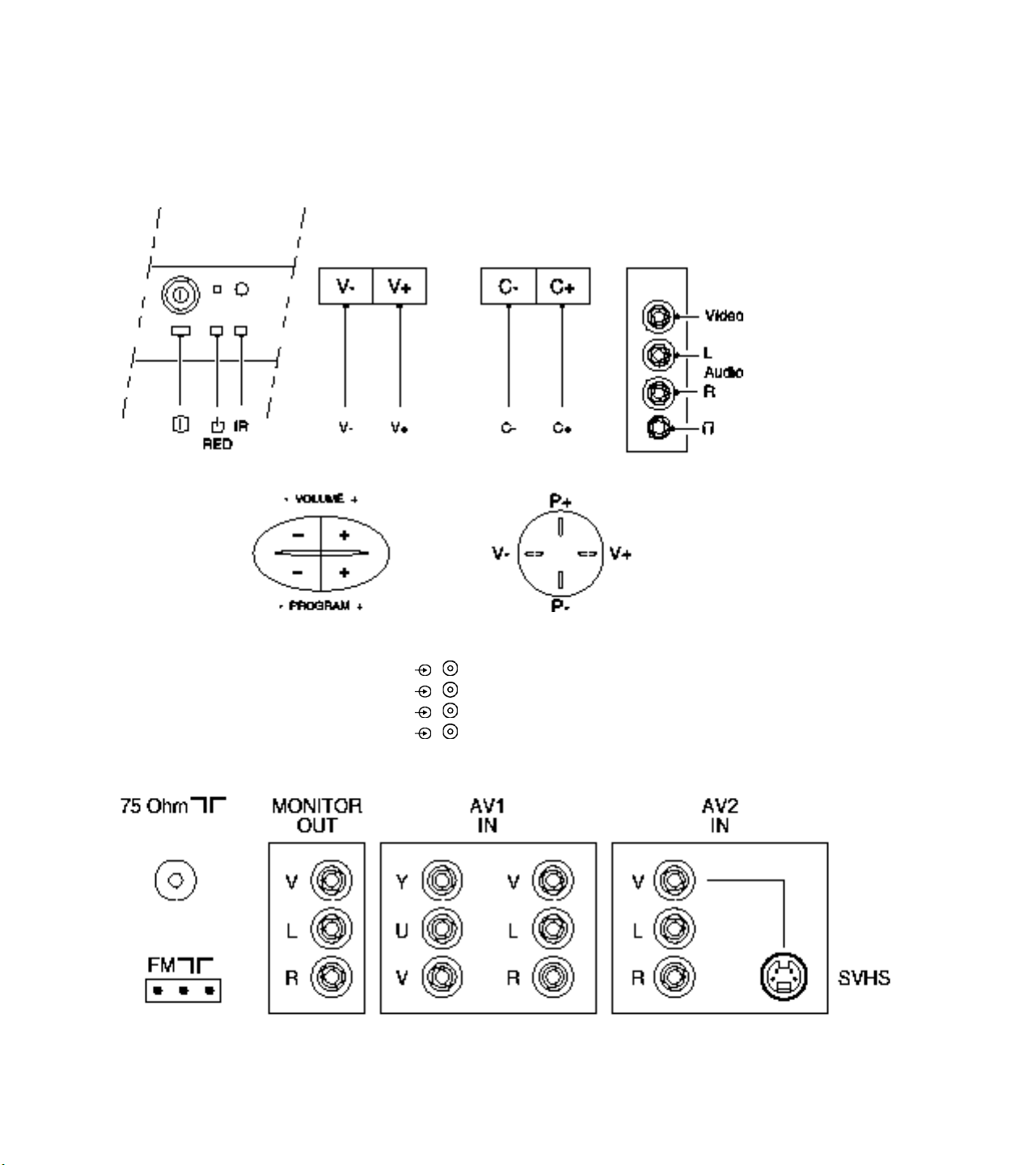
Connections
Front Or Top Control, Front Or Side Connections
Audio / Video In
1 - Video 1 Vpp / 75 Ω
2 - Audio L (0.2 Vrms / 10 kΩ)
3 - Audio R (0.2 Vrms / 10 kΩ)
4 - Headphone (3.5 mm) 8 - 600 Ω/ 4 mW
Rear Connections

Monitor Out
1 - Video 1 Vpp / 75 Ω
2 - Audio L (0.5 Vrms / 1 kΩ)
3 - Audio R (0.5 Vrms / 1 kΩ)
YUV In
1 - Y 0.7 Vpp / 75 Ω
2 - U 0.7 Vpp / 75 Ω
3 - V 0.7 Vpp / 75 Ω
AV1 In
4 - Video 1 Vpp / 75 Ω
5 - Audio L (0.5 Vrms / 10 kΩ)
6 - Audio R (0.5 Vrms / 10 kΩ)
AV2 In
1 - Video 1 Vpp / 75 Ω
2 - Audio L (0.5 Vrms / 10 kΩ)
3 - Audio R (0.5 Vrms / 10 kΩ)
AV2 In (SVHS)
1 - gnd
2 - gnd
3 - Y 1 Vpp / 75 Ω
4 - C 0.3 Vpp / 75 Ω
Maintenance Instructions
It is recommended to have a maintenance inspection carried out by qualified service personnel. The interval depends on the
usage conditions:
• When the set is used under normal circumstances, for example in a living room, the recommended interval is three to
five years.
• When the set is used in an environment with higher dust, grease or moisture levels, for example in a kitchen, the
recommended interval is one year.
• The maintenance inspection includes the following actions:
1. Perform the 'general repair instruction' noted above.
2. Clean the power supply and deflection circuitry on the chassis.
3. Clean the picture tube panel and the neck of the picture tube.

Abbreviation list
2CS 2 Carrier (or Channel) Stereo
ACI Automatic Channel Installation: algorithm that installs TV sets directly from cable network by means
of a predefined TXT page
ADC Analogue to Digital Converter
AFC Automatic Frequency Control: control signal used to tune to the correct frequency
AFT Automatic Fine Tuning
AGC Automatic Gain Control: algorithm that controls the video input of the featurebox
AM Amplitude Modulation
AP Asia Pacific
AR Aspect Ratio: 4 by 3 or 16 by 9
ATS Automatic Tuning System
AV External Audio Video
AVL Automatic Volume Level
BC-PROT Beam Current Protection
BCL Beam Current Limitation
B/G Monochrome TV system. Sound carrier distance is 5.5 MHz
BLCINFORMATION Black current informationrmation
BTSC Broadcast Television Standard Committee. Multiplex FM stereo sound system, originating from the
USA and used e.g. in LATAM and AP-NTSC countries
B-TXT Blue teletext
CC Closed Caption
ComPair Computer aided rePair
CRT Cathode Ray Tube or picture tube
CSM Customer Service Mode
CTI Colour Transient Improvement: manipulates steepness of chroma transients
CVBS Composite Video Blanking and Synchronisation
DAC Digital to Analogue Converter
DBE Dynamic Bass Enhancement: extra low frequency amplification
DBX Dynamic Bass Expander
D/K Monochrome TV system. Sound carrier distance is 6.5 MHz
DFU Direction For Use: description for the end user
DNR Dynamic Noise Reduction
DSP Digital Signal Processing
DST Dealer Service Tool: special remote control designed for dealers to enter e.g. service mode
DVD Digital Versatile Disc
EEPROM Electrically Erasable and Programmable Read Only Memory
EHT Extra High Tension
EHTINFORMATION Extra High Tensioninformationrmation
EU Europe

EW East West, related to horizontal deflection of the set
EXT External (source), entering the set via SCART or Cinch
FBL Fast Blanking: DC signal accompanying RGB signals
FILAMENT Filament of CRT
FLASH Flash memory
FM Field Memory
FM Frequency Modulation
HA Horizontal Acquisition: horizontal sync pulse coming out of the HIP
HFB Horizontal Flyback Pulse: horizontal sync pulse from large signal deflection
HP Headphone
Hue Colour phase control for NTSC (not the same as 'Tint')
I Monochrome TV system. Sound carrier distance is 6.0 MHz
I2C Integrated IC bus
IF Intermediate Frequency
IIC Integrated IC bus
Interlaced Scan mode where two fields are used to form one frame. Each field contains half the number of the
total amount of lines. The fields are written in "pairs", causing line flicker.
ITV Institutional TV
LATAM Latin America
LED Light Emitting Diode
L/L' Monochrome TV system. Sound carrier distance is 6.5 MHz. L' is Band I, L is all bands except for
Band I
LNA Low Noise Amplifier
LS Large Screen
LS Loudspeaker
LSP Large signal panel
M/N Monochrome TV system. Sound carrier distance is 4.5 MHz
MSP Multistandard Sound Processor: ITT sound decoder
MUTE Mute-Line
NC Not Connected
NICAM Near Instantaneous Compounded Audio Multiplexing. This is a digital sound system, mainly used in
Europe.
NTSC National Television Standard Committee. Colour system mainly used in North America and Japan.
Colour carrier NTSC M/N = 3.579545 MHz, NTSC 4.43 = 4.433619 MHz (this is a VCR norm, it is
not transmitted off-air)
NVM Non Volatile Memory: IC containing TV related data e.g. alignments
OB Option Byte
OC Open Circuit
OSD On Screen Display
PAL Phase Alternating Line. Colour system mainly used in West Europe (colour carrier = 4.433619
MHz) and South America (colour carrier PAL M = 3.575612 MHz and PAL N = 3.582056 MHz)
PCB Printed Circuit board
PIP Picture In Picture

PLL Phase Locked Loop. Used for e.g. FST tuning systems. The customer can give directly the desired
frequency
POR Power-On Reset
Progressive Scan Scan mode where all scan lines are displayed in one frame at the same time, creating a double
vertical resolution.
PTP Picture Tube Panel (or CRT-panel)
RAM Random Access Memory
RC Remote Control handset
RC5 Remote Control system 5, signal from the remote control receiver
RGB Red Green Blue
ROM Read Only Memory
SAM Service Alignment Mode
SAP Second Audio Program
SC Sandcastle: pulse derived from sync signals
S/C Short Circuit
SCAVEM Scan Velocity Modulation
SCL Serial Clock
SDA Serial Data
SDM Service Default Mode
SECAM SEequence Couleur Avec Memoire. Colour system mainly used in France and East Europe. Colour
carriers = 4.406250 MHz and 4.250000 MHz
SIF Sound Intermediate Frequency
SS Small Screen
STBY Standby
SVHS Super Video Home System
SW Software
THD Total Harmonic Distortion
TXT Teletext
µP Microprocessor
UOC Ultimate One Chip
VA Vertical Acquisition
VBAT Main supply voltage for the deflection stage (mostly 141 V)
V-chip Violence Chip
VCR Video Cassette Recorder
WYSIWYR What You See Is What You Record: record selection that follows main picture and sound
XTAL Quartz crystal
YC Luminance (Y) and Chrominance (C) signal
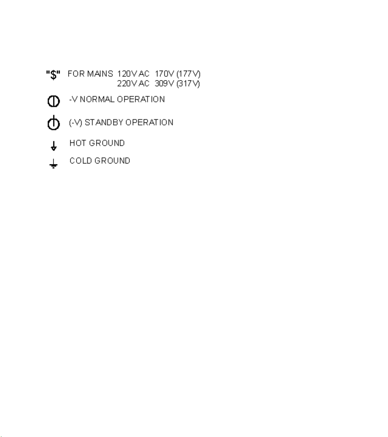
Schematic notes
Service Modes, Error Codes And Fault Finding
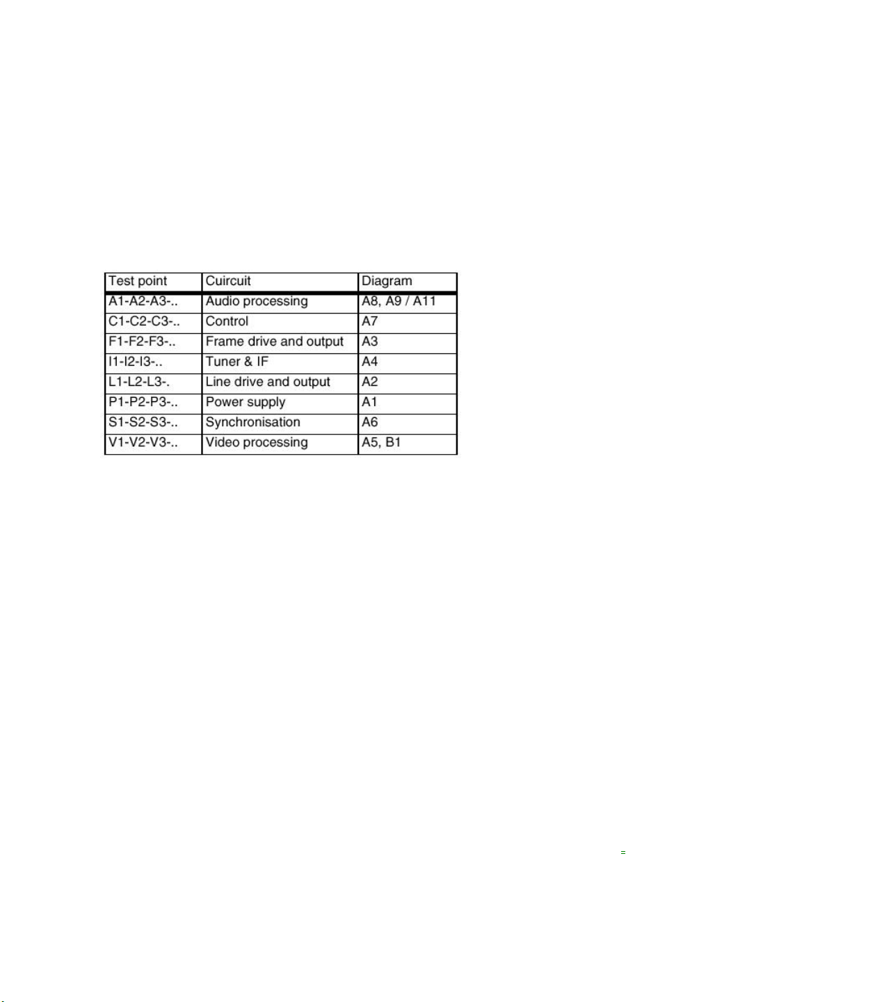
Test Points
The chassis is equipped with test points printed on the circuit board assemblies. These test points refer to the functional
blocks:
The numbering is in a logical sequence for diagnostics.
Always start diagnosing within a functional block in the sequence of the relevant test points for that block.
Perform measurements under the following conditions:
• Service Default Mode (when this mode is not present, set all controls to 50% and volume select channel 3).
• Service Default Mode.
• Video: color bar signal.
• Audio: 3 kHz left, 1 kHz right.
Service Modes
Service Default Mode (SDM) and Service Alignment Mode (SAM) offer several features for the service technician, while the
Customer Service Mode (CSM) is used for communication between dealer and customer.
Note: Some L8 and M8 chassis sets use a software version that does not contain the Service Modes (see table). In this
case, use the special Factory Mode Remote Control. This can be ordered by service code 4835 310 57511. Complete
instructions are included. This remote control will place the TV in the Factory Mode and allow access to all adjustments that
a normal Service Mode contains (including setting Option Bytes). Error codes will not be available.
There is also the option of using ComPair, a hardware interface between a computer (see requirements) and the TV chassis.
It offers the ability of structured trouble shooting, error code reading and software version readout for all L8 and M8 chassis.
Requirements: To run ComPair on a computer (laptop or desktop) requires, as a minimum, a 486 processor, Windows 3.1
and a CD-ROM drive. A Pentium Processor and Windows 95/98 are also acceptable (see also ComPair

Service Default Mode (SDM)
Purpose
• To create a predefined setting to get the same measurement results as given in this manual.
• To override SW protections.
• To start the blinking LED procedure.
Specifications
• Tuning frequency: 61.25 MHz (channel 3).
• Color system: NTSC.
• All picture settings at 50 % (brightness, color contrast, hue).
• Bass, treble and balance at 50 %; volume at 25 %.
• All service-unfriendly modes (if present) are disabled, like:
− (sleep) timer,
− child/parental lock,
− blue mute,
− hotel/hospitality mode
− auto switch-off (when no 'IDENT' video signal is received for 15 minutes),
− skip / blank of non-favorite presets / channels,
− auto store of personal presets,
− auto user menu time -out.

How to enter SDM
• Use a standard customer RC-transmitter and key in the code 062596 directly followed by the MENU button, or
• Short wires 9631 and 9641 on the mono carrier and switch the set ON apply AC power. Then press the power button
(remove short after start-up).
Caution: Entering SDM by shorten wires 9631 and 9641 will override the +8V-protection. Do this only for a short period.
When doing this, the service-technician must know exactly what he is doing, as it could lead to damaging the set.
• Or via ComPair
After entering SDM, the following screen is visible, with SDM at the upper right side for recognition.
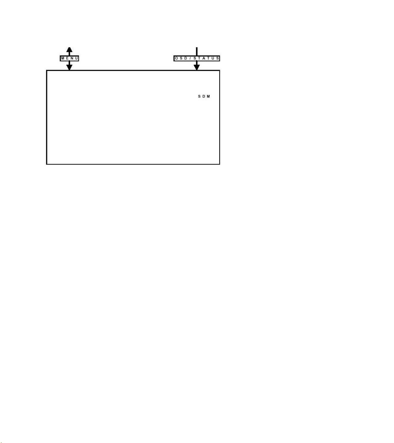
How to navigate
• When you press the MENU button on the remote control, the set will switch between the SDM and the normal user menu
(with the SDM mode still active in the background). Return to the SDM screen with the OSD / STATUS button.
• When you press the OSD / STATUS button on the remote control, the menu will show or hide the error buffer. This
feature is available to prevent interference during waveform measurements.
• On the TV press and hold the 'VOLUME down' and press the 'CHANNEL down' for a few from SDM to SAM and reverse.
How to exit
Switch the set to STANDBY by pressing the power button on the remote control transmitter (if you switch the set OFF by
removing the AC power, the set will return in SDM when AC power is re-applied). The error buffer is cleared.
Service Alignment Mode (SAM)
Purpose
• To perform alignments.
• To change option settings.
• To display / clear the error code buffer.
Specifications
• Operation hours counter.
• Software version.
• Option settings.
• Error buffer reading and erasing.
• Software alignments.
How to enter
• Use a standard customer RC-transmitter and key in the code 062596 directly followed by the OSD / STATUS button or
• Via ComPair.
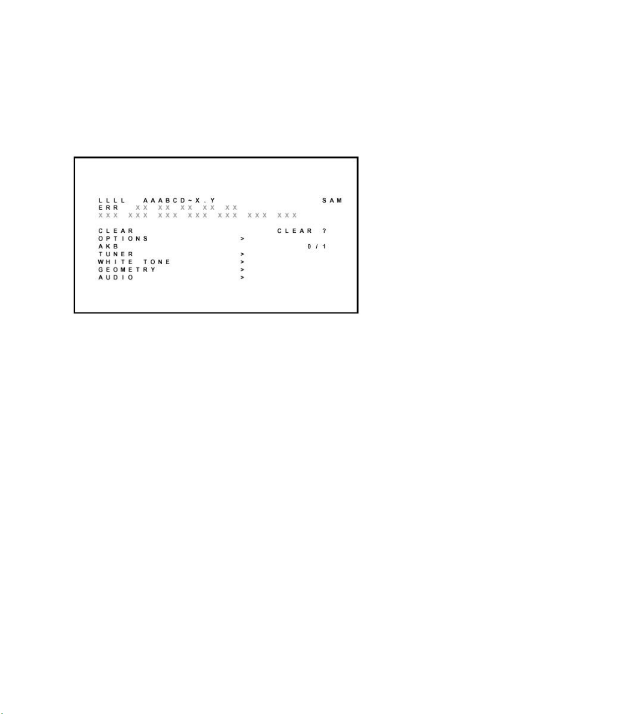
The following screen is visible, with SAM at the upper right side for recognition.
1. LLLL This is the operation hours counter. It counts the normal operation hours, not the standby hours.
2. AAABCD-X.Y This is the software identification of the main micro controller
• A = the project name (L01).
• B = the region: E = Europe, A = Asia Pacific, U = NAFTA, L = LATAM.
• C = the software diversity: N = stereo non-DBX, S = stereo DBX, M = mono, D = DVD.
• D = the language cluster number.
• E = UOC diversity.
• X = the main software version number.
• Y = the sub software version number.
3. SAM Indication of the actual mode.
4. Errors buffer Five errors possible.
5. Option bytes Seven codes possible.
6. Clear Erase the contents of the error buffer. Select the CLEAR menu item and press the CURSOR RIGHT key. The
content of the error buffer is cleared.
7. Options To set the Option Bytes. See chapter 8.3.1 for a detailed description.
8. AKB Disable (0) or enable (1) the 'black current loop' (AKB = Auto Kine Bias).
9. Tuner To align the Tuner. See chapter 8.3.2 for a detailed description.
10. White Tone To align the White Tone. See White tone for a detailed description.
11. Geometry To align the set geometry. See Geometry for a detailed description.
12. Audio No audio alignment is used for NTSC.
How to navigate
• In SAM, select menu items with the CURSOR UP/DOWN key on the remote control transmitter. The selected item will be highlighted.
When not all menu items fit on the screen, move the CURSOR UP/DOWN key to display the next / previous menu items.
• With the CURSOR LEFT/RIGHT keys, it is possible to:
− (De)activate the selected menu item.
− Change the value of the selected menu item.
− Activate the selected submenu.
• When you press the MENU button twice, the set will switch to the normal user menus (with the SAM mode still active in
the background). To return to the SAM menu press the OSD / STATUS button [ i+ ].
• When you press the MENU key in a submenu, you will return to the previous menu.
How to exit
Switch the set to STANDBY by pressing the power button on the remote control transmitter (if you switch the set OFF by
removing the AC power, the set will return in SAM when AC power is re-applied). The error buffer is not cleared.
Customer Service Mode (CSM)
Purpose
The Customer Service Mode is (de-)activated by the customer upon request of the service technician during a telephone conversation,
in order to identify the status of the set. This CSM is a read only mode, therefore modifications in this mode are not possible.
How to enter
The CSM will be turned on after pressing the MUTE key on the remote control transmitter and any of the control buttons on
the TV for at least 4 seconds simultaneously. This activation only works if there is no menu on the screen.
After switching ON the Customer Service Mode, the following screen will appear:
1. Software identification of the main micro controller (see Service Alignment Mode (SAM)for an explanation).
2. Error code buffer (see Error Codes for more details). Displays the last seven errors of the error code buffer.
3. In this line, the Option Bytes (OB) are visible. Each Option Byte is displayed as a decimal number between 0 and 255. The
set may not work correctly when an incorrect option code is set. See Options for more information on the option settings.
4. Indicates which color and sound system is installed for the selected pre-set.

5. Indicates if the set is not receiving an 'IDENT' signal on the selected source. It will display 'Not Tuned'.
6. Indicates if the sleep timer is enabled.
7. Indicates if the V-chip feature is enabled.
8. Value indicates parameter levels at CSM entry.
CO = CONTRAST, CL = COLOR, BR = BRIGHTNESS,
HU = HUE, SH = SHARPNESS
9. Value indicates parameter levels at CSM entry.
VL = VOLUME LEVEL, BL = BALANCE LEVEL, AVL LIM
= AUTO VOLUME LEVEL LIMITER
10. Value indicates parameter levels at CSM entry.
DV = DELTA VOLUME, BS = BASS LEVEL, TR = TREBLE LEVEL
How to exit
You can turn the Customer Service Mode off:
• After you press 'any' key of the remote control transmitter with exception of the CHANNEL and VOLUME keys.
• After you switch-off the TV set with the AC power switch.
Problems And Solving Tips (Related To CSM)
Picture Problems
No colors / noise in picture
Check CSM line 4. Wrong color system installed. To change the setting:
1. Select the MANUAL STORE sub menu.
2. Select and change the SYSTEM setting until picture and sound are correct.
3. Select the STORE menu item.
Colors not correct / unstable picture
Check CSM line 4. Wrong color system installed. To change the setting:
1. Press the MENU button on the remote control.
2. Select the INSTALL sub menu.
3. Select the MANUAL STORE sub menu.
4. Select and change the SYSTEM setting until picture and sound are correct.
5. Select the STORE menu item.
TV switches off or changes channel without any user action
The TV set switches off after TV SWITCHING OFF was displayed.
Auto standby switched the set off because:
• There was no 'ident' signal for more than 15 minutes or
• There was no remote control signal received or local key pressed for > 2 hours.
See Alignments for a description of the options to enable / disable auto standby

Picture too dark or too bright
Increase / decrease the BRIGHTNESS and / or the CONTRAST value when:
• The picture improves after you have pressed the 'Smart Picture' button on the remote control.
• The picture improves after you have switched on the Customer Service Mode
The new 'Personal' preference value is automatically stored.
White line around picture elements and text
Decrease the SHARPNESS value when:
• The picture improves after you have pressed the 'Smart Picture' button on the remote control.
• The picture improves after you have switched on the Customer Service Mode
The new 'Personal' preference value is automatically stored.
Snowy picture
Check CSM line 5. If this line indicates 'Not Tuned', check the following:
• No or bad antenna signal. Connect a proper antenna signal.
• Antenna not connected. Connect the antenna.
• No channel / preset is stored at this program number. Go to the INSTALL menu and store a proper channel at this
program number.
• The tuner is faulty (in this case the CODES line will contain error number 10). Check the tuner and replace / repair if
necessary.
Snowy picture and/or unstable picture
• A scrambled or decoded signal is received.
Black and white picture
Increase the COLOR value when:
• The picture improves after you have pressed the 'Smart Picture' button on the remote control.
• The picture improves after you have switched on the Customer Service Mode
The new 'Personal' preference value is automatically stored.
Menu text not sharp enough
Decrease the CONTRAST value when:
• The picture improves after you have pressed the 'Smart Picture' button on the remote control.
• The picture improves after you have switched on the Customer Service Mode
The new 'Personal' preference value is automatically stored.
Sound Problems
No sound or sound too loud (after channel change / switching on)
Increase / decrease the VOLUME level when the volume is OK after you switched on the CSM. The new 'Personal'
preference value is automatically stored.

ComPair
Introduction
ComPair (Computer Aided Repair) is a service tool for Philips Consumer Electronics products. ComPair is a further
development on the European DST (service remote control), which allows faster and more accurate diagnostics. Compare
has three big advantages:
• ComPair helps you to quickly get an understanding on how to repair the chassis in a short time by guiding you
systematically through the repair procedures.
• ComPair allows very detailed diagnostics (on I2C level) and is therefore capable of accurately indicating problem areas.
You do not have to know anything about I 2 C commands yourself because ComPair takes care of this.
• ComPair speeds up the repair time since it can automatically communicate with the chassis (when the microprocessor is
working) and all repair information is directly available. When ComPair is installed together with the SearchMan
electronic manual of the defective chassis, schematics and PWBs are only a mouse click away.
Specifications
ComPair consists of a Windows based faultfinding program and an interface box between PC and the (defective) product.
The ComPair interface box is connected to the PC via a serial or RS232 cable.
In case of the L8/M8 chassis, the ComPair interface box and the TV communicate via a bi-directional service cable via the
service connector (located on the Main panel, see Hardware alignments suffix D).
The ComPair faultfinding program is able to determine the problem of the defective television. ComPair can gather
diagnostic information in two ways:
1. Automatic (by communication with the television)
ComPair can automatically read out the contents of the entire error buffer. Diagnosis is done on I 2 C level. ComPair can
access the I 2 C bus of the television. ComPair can send and receive I 2 C commands to the micro controller of the
television. In this way, it is possible for ComPair to communicate (read and write) to devices on the I 2 C busses of the
TV-set.
2. Manually (by asking questions to you)
Automatic diagnosis is only possible if the micro controller of the television is working correctly and only to a certain
extend. When this is not the case, ComPair will guide you through the faultfinding tree by asking you questions (e.g.
Does the screen gives a picture? Click on the correct answer: YES / NO) and showing you examples (e.g. Measure testpoint I7 and click on the correct oscillogram you see on the oscilloscope). You can answer by clicking on a link (e.g. text
or a waveform picture) that will bring you to the next step in the faultfinding process.
By a combination of automatic diagnostics and an interactive question / answer procedure, ComPair will enable you to find
most problems in a fast and effective way.
Beside fault finding, ComPair provides some additional features like:
• Up- or downloading of presets.
• Managing of preset lists.
• Emulation of the (European) Dealer Service Tool (DST).
• If both ComPair and SearchMan (Electronic Service Manual) are installed, all the schematics and the PWBs of the set
are available by clicking on the appropriate hyperlink.
Example: Measure the DC-voltage on capacitor C2568 (Schematic/Panel) at the Monocarrier.
Click on the 'Panel' hyperlink to automatically show the PWB with a highlighted capacitor C2568.
Click on the 'Schematic' hyperlink to automatically show the position of the highlighted capacitor.
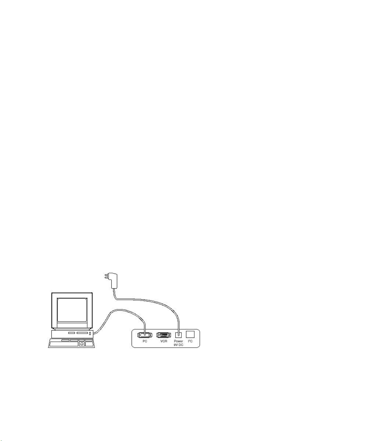
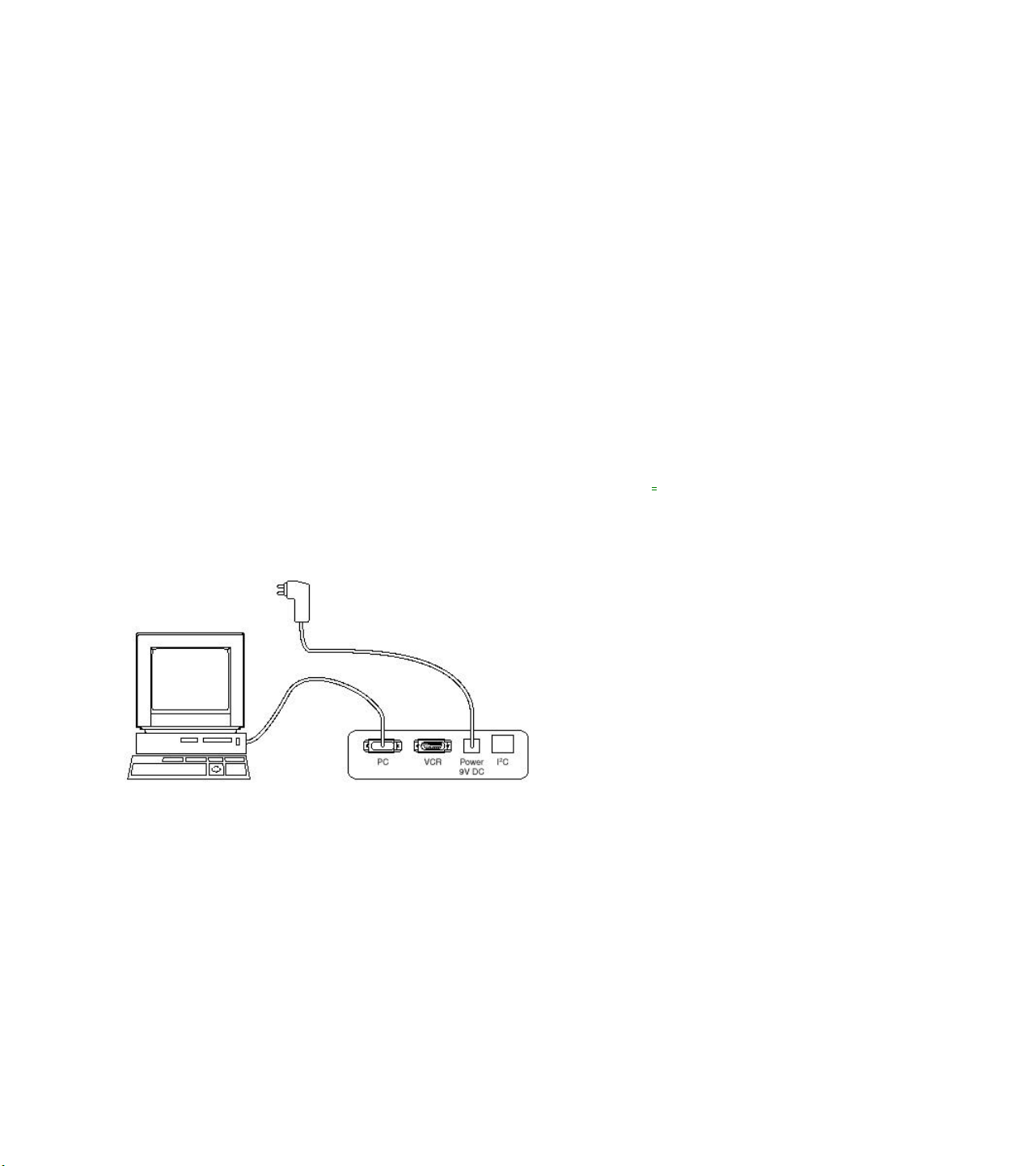
How To Connect
1. First install the ComPair Browser software (see the Quick Reference Card for installation instructions).
2. Connect the RS232 interface cable between a free serial (COM) port of your PC and the PC connector (marked with
'PC') of the ComPair interface.
3. Connect the AC power adapter to the supply connector (marked with 'POWER 9V DC') on the compare interface.
4. Switch the ComPair interface OFF.
5. Switch the television set OFF, remove the AC power.
6. Connect the ComPair interface cable between the connector on the rear side of the ComPair interface (marked with 'I 2
C') and the ComPair connector on the mono carrier (see Hardware alignments suffix D).
7. Plug the AC power adapter in the AC power outlet and switch on the interface. The green and red LEDs light up together.
The red LED extinguishes after approx. 1 second while the green LED remains lit.
8. Start the ComPair program and read the introduction chapter.
How To Order
ComPair order codes:
• Starter kit ComPair + SearchMan software + compare interface (excluding transformer): 4822 727 21629
• ComPair interface (excluding transformer): 4822 727 21631
• Starter kit ComPair software (registration version): 4822 727 21634
• Starter kit SearchMan software: 4822 727 21635
• ComPair CD (update): 4822 727 21637
• SearchMan CD (update): 4822 727 21638
• ComPair interface cable: 3122 785 90004

Error Codes
Introduction
The error code buffer contains all errors detected since the last time the buffer was erased. The buffer is written from left to
right. When an error occurs that is not yet in the error code buffer, it is written at the left side and all other errors shift one
position to the right.
The error code buffer is cleared in the following cases:
• By activation of the CLEAR command in the SAM menu:
• When you exit SDM / SAM with the STANDBY command on the remote control (when leaving SDM / SAM, by
disconnecting the set from AC power, the error buffer is not reset).
• When you transmit the command DIAGNOSE-99-OK with ComPair.
• If the content of the error buffer has not changed for 50 hours, it resets automatically.
Examples:
ERROR: 0 0 0 0 0: No errors detected.
ERROR: 6 0 0 0 0: Error code 6 is the most recent and only detected error.
ERROR: 9 6 0 0 0: Error code 6 was first detected and error code 9 is the most recent detected error.
You can also make the contents of the error buffer visible via the blinking LED procedure (see The Blinking LED
Procedure). This is especially useful when there is no picture.
Error Codes
In case of non-intermittent faults, clear the error buffer before you begin the repair. These to ensure that old error codes are
no longer present.
If possible, check the entire contents of the error buffer. In some situations an error code is only the result of another error
code and not the actual cause (e.g., a fault in the protection detection circuitry can also lead to a protection).

The Blinking LED Procedure
Via this procedure you can make the contents of the error buffer visible via the front LED. This is especially useful when
there is no picture.
When the SDM is entered, the LED will blink the contents of the error-buffer.
Error-codes ≥ 10 are shown as follows:
− a long blink of 750 ms (which is an indication of the decimal digit),
− a pause of 1.5 s,
− n short blinks (n = 1 - 9),
− when all the error-codes are displayed, the sequence finishes with a LED blink of 3 s,
− the sequence starts again.
Example of error buffer: 12 9 6 0 0
After entering SDM:
− 1 long blink of 750 ms followed by a pause of 1.5 s,
− 2 short blinks followed by a pause of 3 s,
− 9 short blinks followed by a pause of 3 s,
− 6 short blinks followed by a pause of 3 s,
− 1 long blink of 3 s to finish the sequence,
− the sequence starts again.

Protections
If a fault situation is detected an error code will be generated and if necessary the set will be put in the protection mode.
Blinking of the red LED at a frequency of 3 Hz indicates the protection mode. In some error cases the microprocessor does
not put the set in the protection mode. The error codes of the error buffer can be read via the service menu (SAM), the
blinking LED procedure or via ComPair. The DST diagnose functionality will force the set into the Service-standby, which is
similar to the usual standby mode, however the microprocessor has to remain in normal operation completely.
To get a quick diagnosis the chassis has three service modes implemented:
• The Customer Service Mode (CSM).
• The Service Default Mode (SDM). Start-up of the set in a predefined way.
• The Service Alignment Mode (SAM). Adjustment of the set via a menu and with the help of test patterns.
See for a detailed description Circuit description
Repair Tips
Below some failure symptoms are given, followed by a repair tip.
• Set is dead and makes hiccuping sound
'MainSupply' is available. Hiccupping stops when de-soldering L5561, meaning that problem is in the 'MainSupply' line.
No output voltages at LOT, no horizontal deflection. Reason: line transistor 7460 is defective.
• Set is dead, and makes no sound
Check power supply IC 7520. Result: voltage at pins 1, 3, 4, 5 and 6 are about 180 V and pin 8 is 0 V. The reason why
the voltage on these pins is so high is because the output driver (pin 6) has an open load. That is why MOSFET 7521 is
not able to switch. Reason: feedback resistor 3523 is defective. Caution: be careful measuring on the gate of 7521;
circuitry is very high ohmic and can easily be damaged!
• Set is in hiccup mode and shuts down after 8 s.
Blinking LED (set in SDM mode) indicates error 5. As it is unlikely that ?P 'POR' and '+8V protection' happen at the same
time, measure the '+8V'. If this voltage is missing, check transistor 7480.
• Set is non-stop in hiccup mode
Set is in over current mode; check the secondary sensing (opto coupler 7515) and the 'MainSupply' voltage. Signal
'Stdby_con' must be logic low under normal operation conditions and goes to high (3.3 V) under standby and fault
conditions.
• Set turns on, but without picture and sound
The screen shows snow, but OSD and other menus are okay. Blinking LED procedure indicates error 11, so problem is
expected in the tuner (pos. 1000). Check presence of supply voltages. As 'Vlotaux+5V' at pin 5 and 7 are okay,
'VT_supply' at pin 9 is missing.
Conclusion: resistor 3460 is defective.
• Set turns on, but with a half screen at the bottom.
Sound is okay
Blinking LED (set in SDM mode) indicates error 3. Check 'Vlotaux+11V' and '+50V'. If they are okay, problem is expected
in the vertical amplifier IC 7471. Measure with a scope the waveform on pin 17 of the UOC. Measure also at pin 1 of IC
7471. If here the signal is missing, a defective resistor R3244 causes the problem.

 Loading...