

Philips 655 CT6558 Service Manual
Depart. Technical support- CM640 PROCEDURE COMPANY RESTRICTED
PHILIPS Consumer
Communications
Centre du Mans
Service Repair Support
VY-V-640-P655
Page : 1 of 74
Langue : EN
Date : 03/01/05
SERVICE MANUAL
Repair for Cellular Telephone
PHILIPS 655 – CT6558
LEVEL 2
PHILIPS ELECTRONICS N.V. 1999 VY-V-640-P655
All rights reserved. Reproduction in whole
or in part is prohibited without the written
consent of the copyright owner.
Depart. Technical support- CM640 PROCEDURE COMPANY RESTRICTED
PHILIPS Consumer
Communications
Centre du Mans
Service Repair Support
VY-V-640-P655
Page : 2 of 74
Langue : EN
Date : 03/01/05
SERVICE MANUAL
Last updates:
DATE MODIFICATION PAGE
03/01/2005 CREATION 79
01/04/2005
- Remove instruction about LCD
module dismantlement
57,58,59,61,62
PHILIPS ELECTRONICS N.V. 1999 VY-V-640-P655
All rights reserved. Reproduction in whole
or in part is prohibited without the written
consent of the copyright owner.

Depart. Technical support- CM640 PROCEDURE COMPANY RESTRICTED
PHILIPS Consumer
Communications
Centre du Mans
Service Repair Support
VY-V-640-P655
Page : 3 of 74
Langue : EN
Date : 03/01/05
CONTENTS
1.0 PURPOSE .....................................................................................................................................4
2.0 SCOPE............................................................................................................................................4
3.0 REFERENCE ..............................................................................................................................4
4.0 GLOSSARY / ACRONYM LIST .........................................................................................4
5.0 TEST EQUIPMENT AND TOOLS.....................................................................................4
6.0 TEST AND INSPECTION PLAN........................................................................................5
6.1 USER INTERFACE TEST ...................................................................................................................5
6.2 RF T
EST .........................................................................................................................................5
7.0 BEFORE STARTING...............................................................................................................7
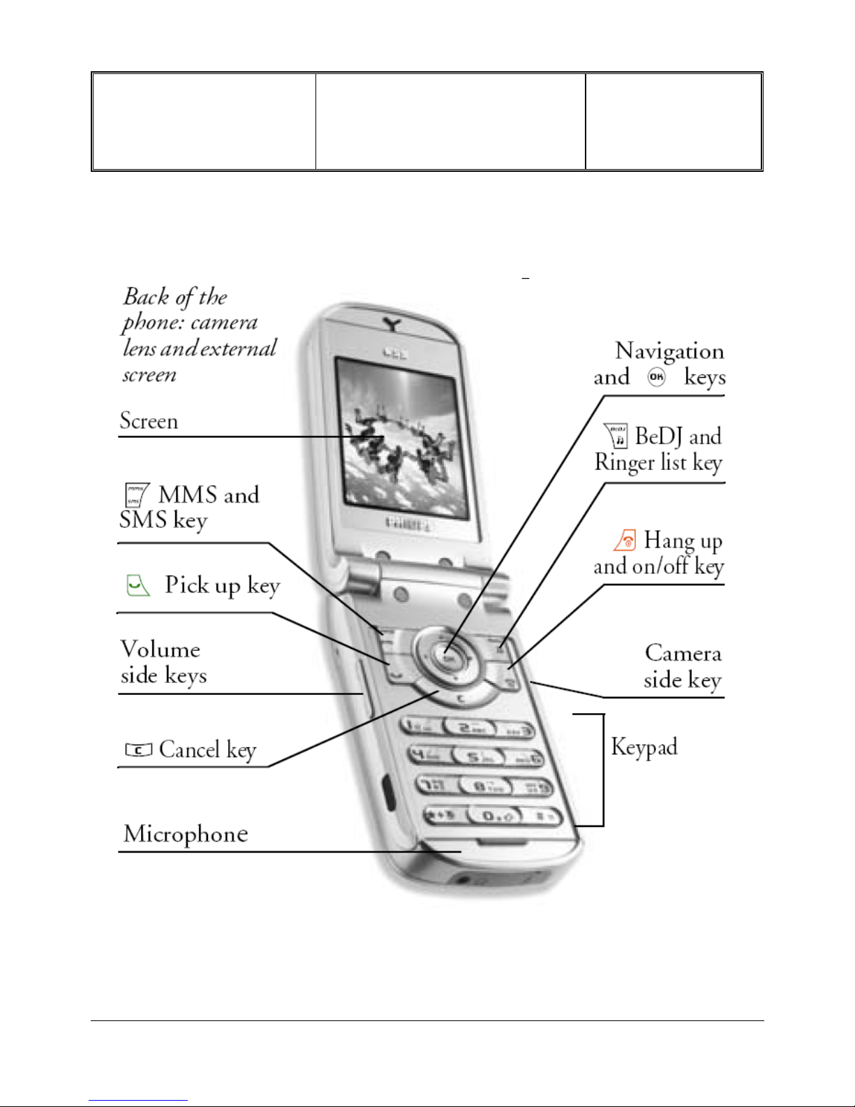
7.1 DESCRIPTION OF THE TRANSCEIVER ..............................................................................................7
7.2 D
ESCRIPTION OF THE DISPLAY ......................................................................................................8
7.3 U
SING THE CAROUSEL....................................................................................................................9
7.4 R
EMOVE BACK COVER .................................................................................................................11
7.5 I
NSERTING THE SIM CARD............................................................................................................11
7.6 I
NSERTING THE BATTERY .............................................................................................................12
7.7 R
EPLACE BACK COVER. ...............................................................................................................12
7.8 C
HARGING THE BATTERY.............................................................................................................13
7.9 B
EDJ QUICK PRESENTATION ........................................................................................................14
7.10 I
NFRARED QUICK PRESENTATION .................................................................................................15
7.11 MMS Q
UICK PRESENTATION........................................................................................................16
7.12 JAVA QUICK PRESENTATION.........................................................................................................16
7.13 TV S
LIDESHOW QUICK PRESENTATION ........................................................................................16
8.0 TEST PROCEDURES ............................................................................................................17
8.1 INITIAL FUNCTIONAL CHECK FOR PHILIPS 655 ...........................................................................17
8.2 RF T
EST .......................................................................................................................................21
8.3 B
ATTERY CHARGING (IGN : IGNITION) / CURRENT CONSUMPTION ..............................................27
8.4 W@P TEST PROCEDURE...............................................................................................................29
8.5 E-MAIL T
EST PROCEDURE ..........................................................................................................35
8.6 MMS TEST PROCEDURE ...............................................................................................................37
8.7 J
AVA TEST PROCEDURE ................................................................................................................39
8.8 I
NFRARED TEST PROCEDURE ........................................................................................................41
8.9 B
EDJ TEST PROCEDURE................................................................................................................42
8.10 C
AMERA TEST PROCEDURE ..........................................................................................................43
9.0 ASSEMBLY / DISMANTLEMENT PROCEDURES ................................................44
9.1 DISMANTLEMENT .........................................................................................................................44
9.2 BOARD E
XCHANGE COMPONENT ................................................................................................56
9.3 A
SSEMBLY....................................................................................................................................57
9.4 C
OSMETIC DEFINE ........................................................................................................................68
9.5 EXPLODED VIEW ...........................................................................................................................69
10.0 SOLUTIONS IN CASE OF PROBLEMS DURING THE TESTS ....................71
11.0 RECOMMENDED PART LIST CT6558 PHILIPS 655........................................73
PHILIPS ELECTRONICS N.V. 1999 VY-V-640-P655
All rights reserved. Reproduction in whole
or in part is prohibited without the written
consent of the copyright owner.
Depart. Technical support- CM640 PROCEDURE COMPANY RESTRICTED
PHILIPS Consumer
Communications
Centre du Mans
Service Repair Support
VY-V-640-P655
Page : 4 of 74
Langue : EN
Date : 03/01/05
1.0 PURPOSE
This document establishes the functional test and inspection procedures for the second level service repair of the
Philips 655 transceiver.
2.0 SCOPE
The test plan is applicable to all levels of service repair of the Philips 655 transceiver.
3.0 REFERENCE
None.
4.0 GLOSSARY / ACRONYM LIST
Window or Bezzel Protective plastic over the LCD display
SW Software
PN Hardware Configuration of the Mobile
CN Matrix for Types of SW used on the different hardware
HW Hardware
ASC Authorized Service Center
NSC National Service Center
Test SIM Card Used for functionality of PHILIPS Mobile Phones
Test SIM Card « SP » SIM Card used to simulate the user interface and enable radio tests
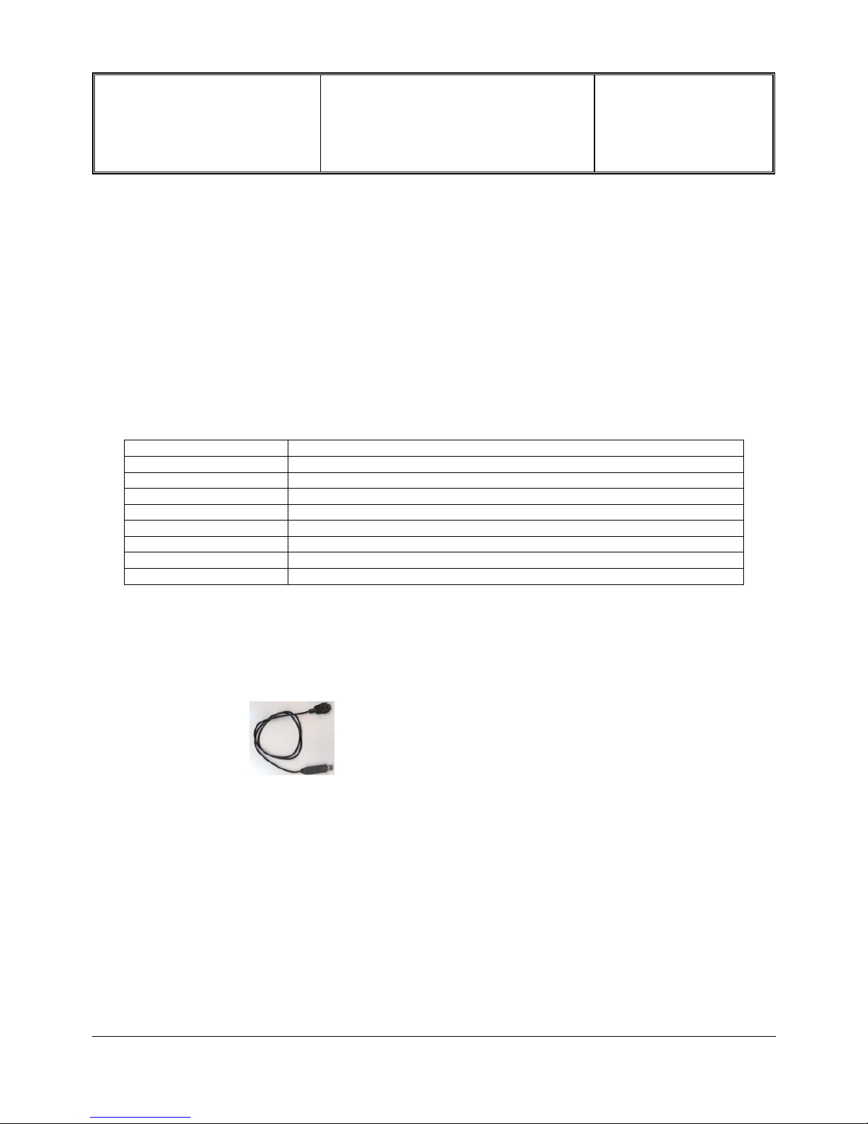
5.0 TEST EQUIPMENT AND TOOLS
Equipment / Tools
- Test SIM Card « Production » - Part No. : 4311 255 00781
- Test SIM Card « SP » - Part No. : 4311 255 00782
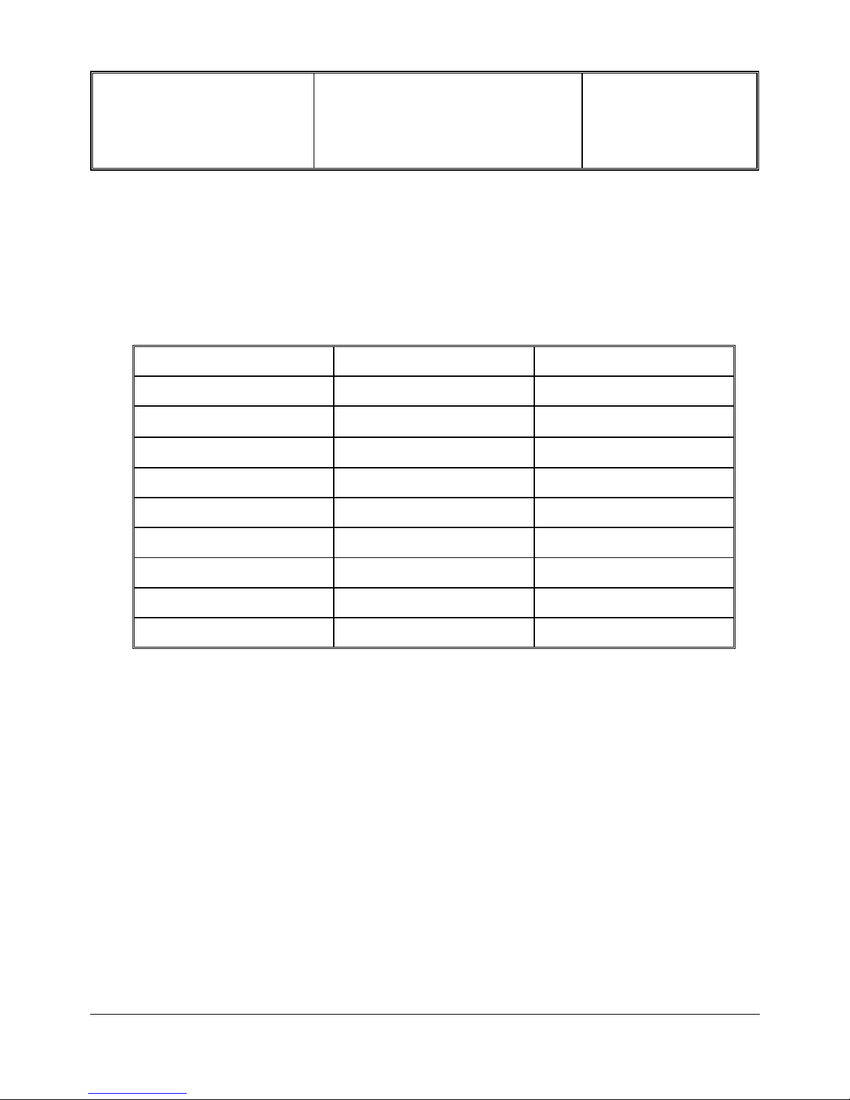
- Data Connect Cable - Part No. : 4311 255 22276
- Digital Multimeter - Recommended Model : Fluke (Specification with current reading in mA).
- Specific Screw Driver : Torx 0.6
- Paper Cut tool
- Digital Radio communication Tester.
- Coupling system with shielded chamber ONLY.
PHILIPS ELECTRONICS N.V. 1999 VY-V-640-P655
All rights reserved. Reproduction in whole
or in part is prohibited without the written
consent of the copyright owner.
Depart. Technical support- CM640 PROCEDURE COMPANY RESTRICTED
PHILIPS Consumer
Communications
Centre du Mans
Service Repair Support
VY-V-640-P655
Page : 5 of 74
Langue : EN
Date : 03/01/05
6.0 TEST AND INSPECTION PLAN
The test plan is derived from the Product Test Reference of PHILIPS 655.
6.1 User Interface Test
Use the Test SIM Card to test the transceivers as follows :
• On/Off button
• LCD Backlight
• Keyboard Test
• Side Keys
• Buzzer Test
• Vibrator Test
• Audio Test
• Antenna Test ( to measure the radiated power level. Not necessary when using an
antenna coupler)
• LCD
• IMEI
• Tester Status/Eeprom Status
With a fast Charger connected with the PRODUCT’s bottom connector, check the full scrolling from one mode to
the next when charging IGN (Ignition) – Battery.
6.2 RF Test
The purpose of the radio test is to prove that the tested phone is compliant to the Standard.
The radio test must be performed with a
Digital Radio Test Set. The mobile has to
be set on the antenna coupler inside the
shielded chamber.
Due to a not accessible RF connector when the Product is closed, it will be necessary to make radio test inside
Shielded chamber only.
See Help Radio Files Over the antenna - RF Calibration.pdf & Over the antenna - The equipments.pdf under the
Internet Web Site :
http://philipscscc.soft2you.net/
in " Technical Support \ Component List \ Wireless \ PHILIPS 639 " section
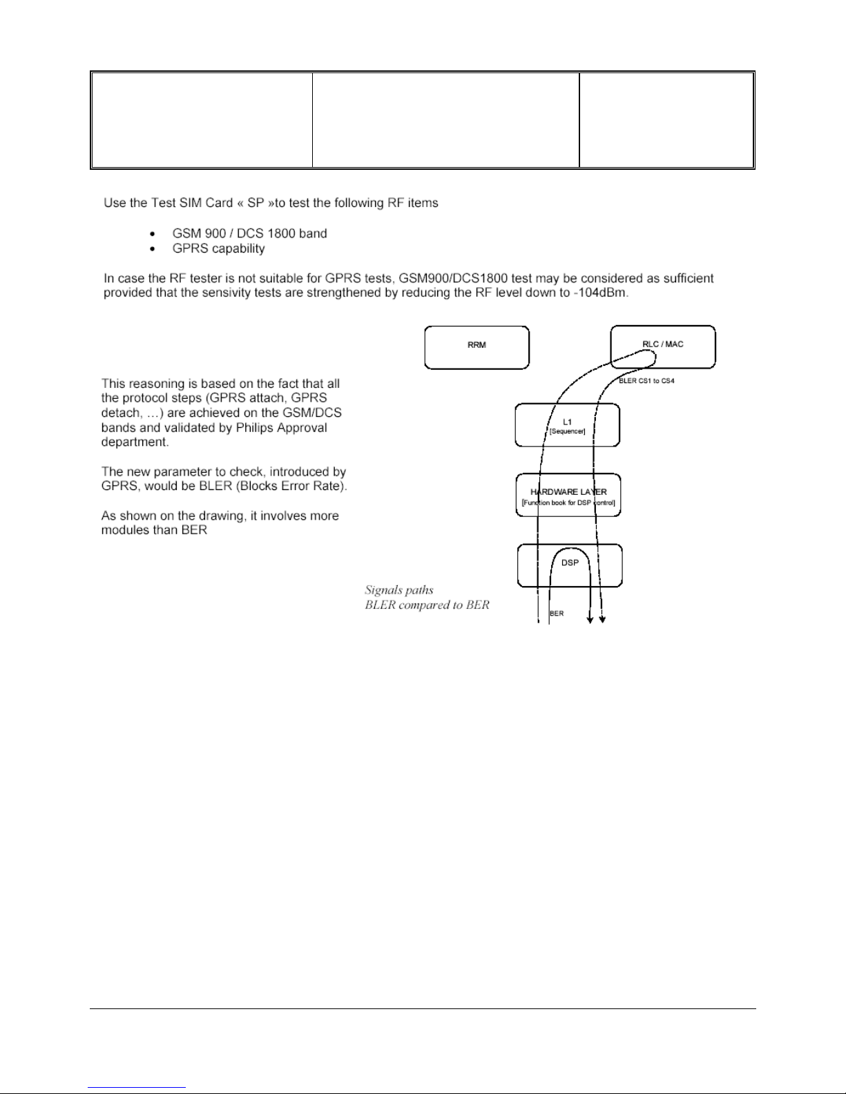
Use the Test SIM Card « SP »to test the GSM 900 / DCS 1800 band
PHILIPS ELECTRONICS N.V. 1999 VY-V-640-P655
All rights reserved. Reproduction in whole
or in part is prohibited without the written
consent of the copyright owner.
Depart. Technical support- CM640 PROCEDURE COMPANY RESTRICTED
PHILIPS Consumer
Communications
Centre du Mans
Service Repair Support
VY-V-640-P655
Page : 6 of 74
Langue : EN
Date : 03/01/05
PHILIPS ELECTRONICS N.V. 1999 VY-V-640-P655
All rights reserved. Reproduction in whole
or in part is prohibited without the written
consent of the copyright owner.
Depart. Technical support- CM640 PROCEDURE COMPANY RESTRICTED
PHILIPS Consumer
Communications
Centre du Mans
Service Repair Support
VY-V-640-P655
Page : 7 of 74
Langue : EN
Date : 03/01/05
7.0 BEFORE STARTING
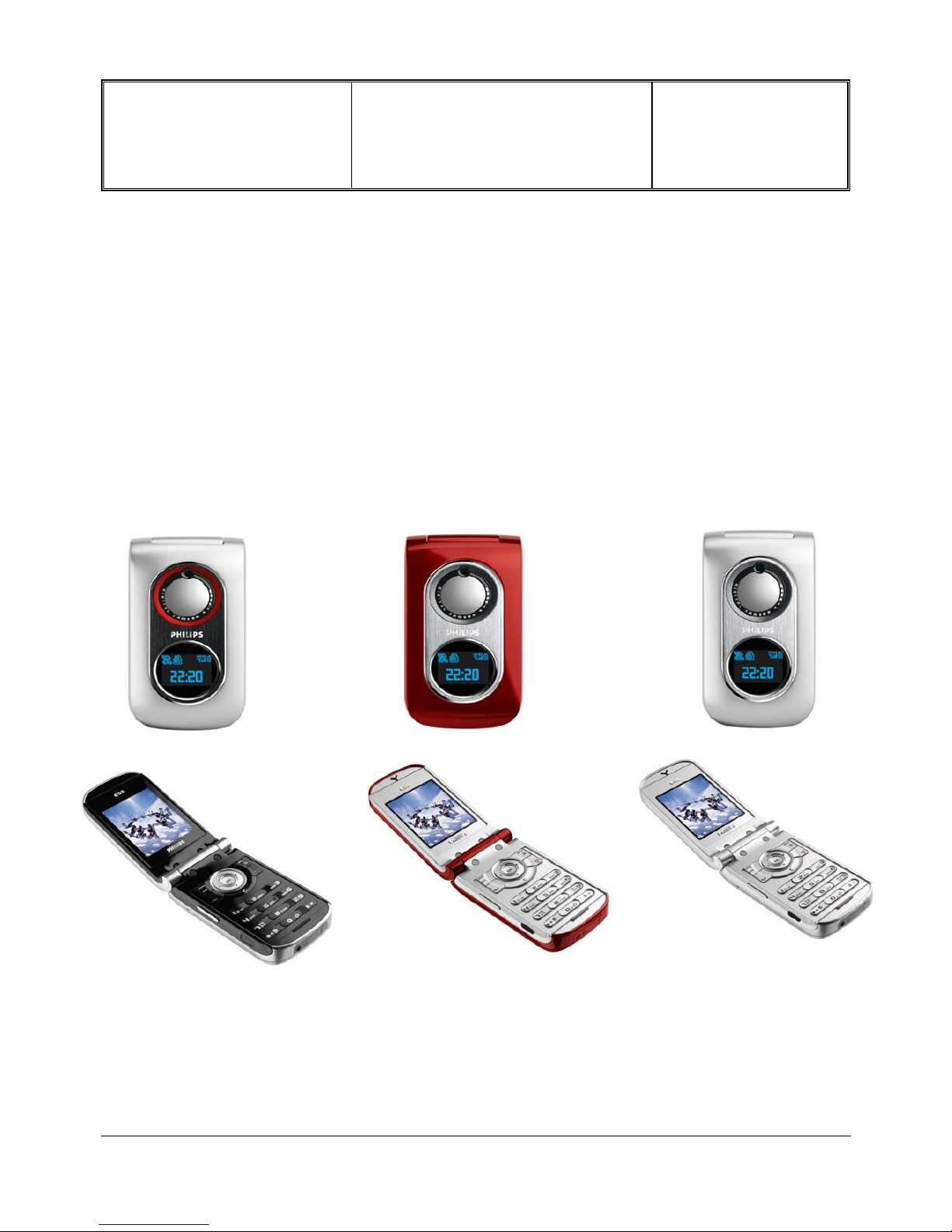
7.1 Description Of The Transceiver
PHILIPS ELECTRONICS N.V. 1999 VY-V-640-P655
All rights reserved. Reproduction in whole
or in part is prohibited without the written
consent of the copyright owner.
Depart. Technical support- CM640 PROCEDURE COMPANY RESTRICTED
PHILIPS Consumer
Communications
Centre du Mans
Service Repair Support
VY-V-640-P655
Page : 8 of 74
Langue : EN
Date : 03/01/05
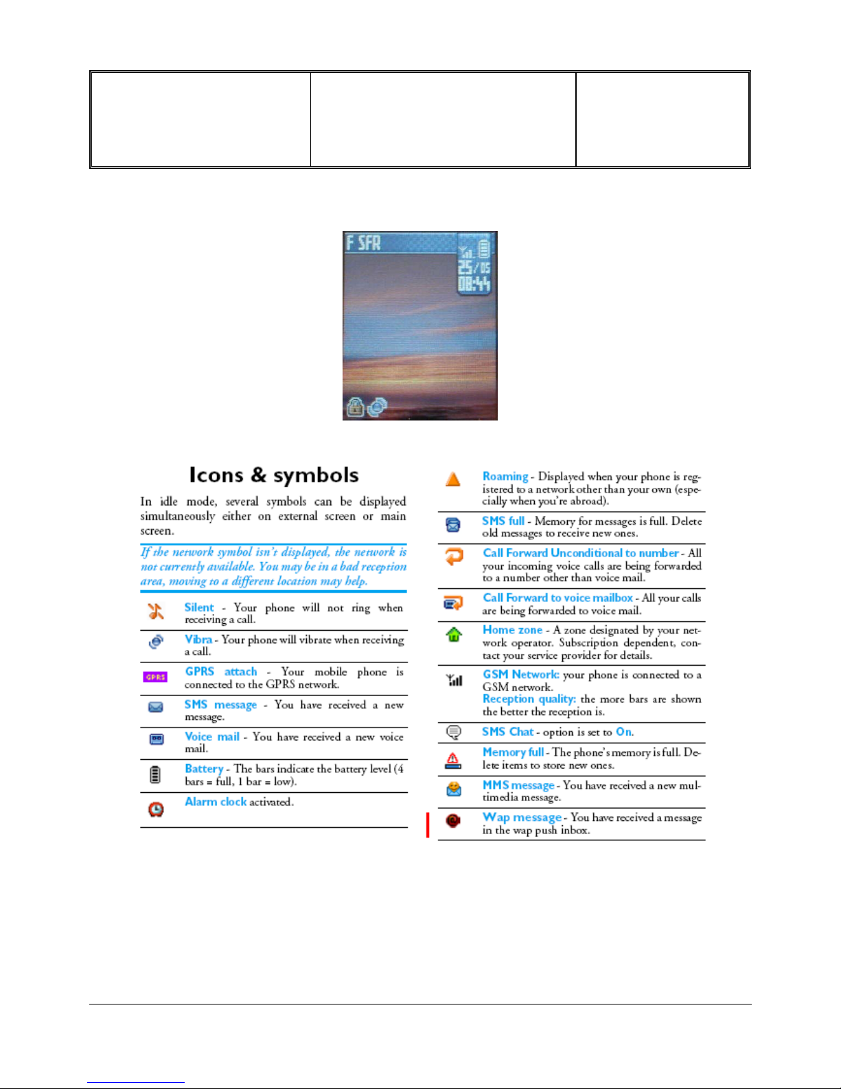
7.2 Description Of The Display
PHILIPS ELECTRONICS N.V. 1999 VY-V-640-P655
All rights reserved. Reproduction in whole
or in part is prohibited without the written
consent of the copyright owner.
Depart. Technical support- CM640 PROCEDURE COMPANY RESTRICTED
PHILIPS Consumer
Communications
Centre du Mans
Service Repair Support
VY-V-640-P655
Page : 9 of 74
Langue : EN
Date : 03/01/05
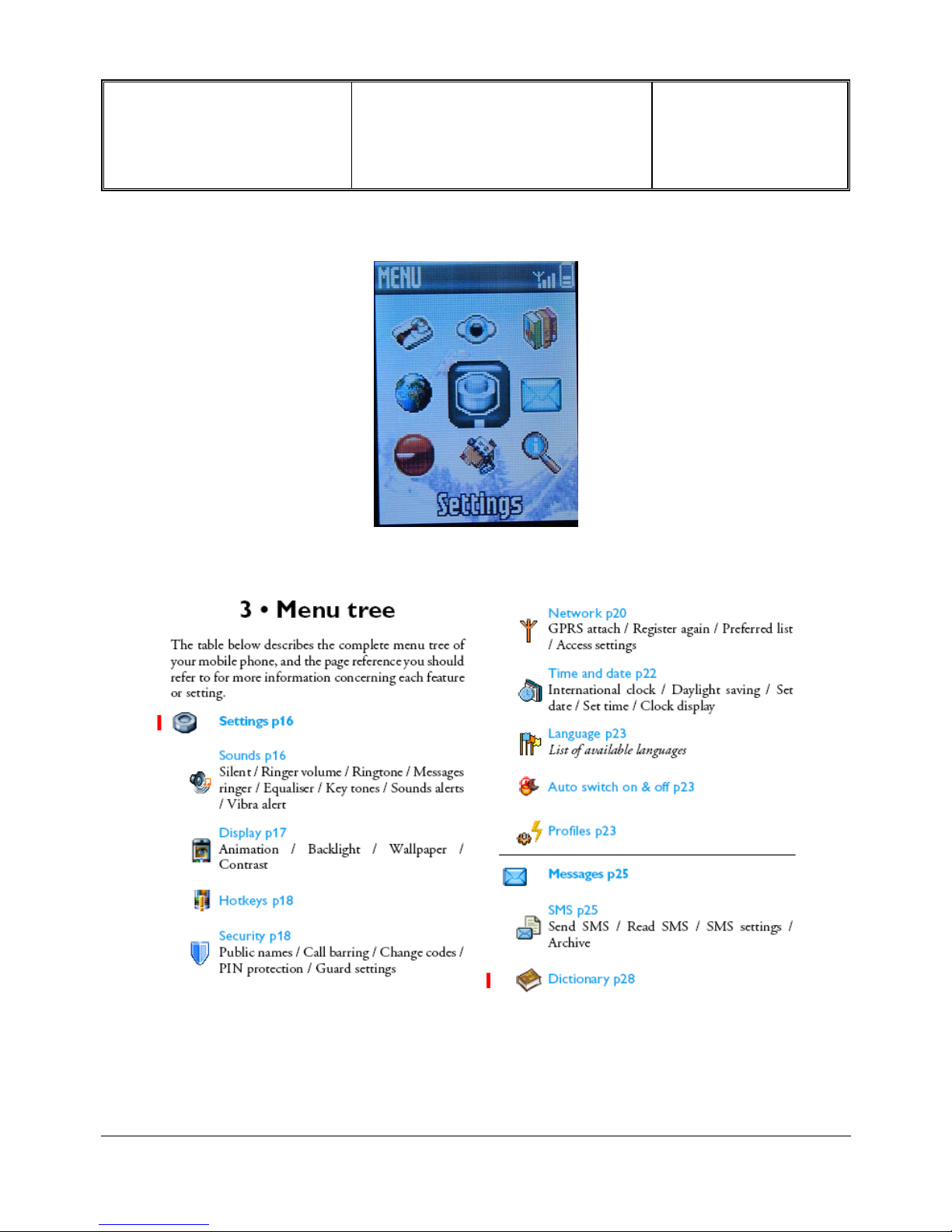
7.3 Using The Carousel
PHILIPS ELECTRONICS N.V. 1999 VY-V-640-P655
All rights reserved. Reproduction in whole
or in part is prohibited without the written
consent of the copyright owner.

Depart. Technical support- CM640 PROCEDURE COMPANY RESTRICTED
PHILIPS Consumer
Communications
Centre du Mans
Service Repair Support
VY-V-640-P655
Page : 10 of 74
Langue : EN
Date : 03/01/05
PHILIPS ELECTRONICS N.V. 1999 VY-V-640-P655
All rights reserved. Reproduction in whole
or in part is prohibited without the written
consent of the copyright owner.
Depart. Technical support- CM640 PROCEDURE COMPANY RESTRICTED
PHILIPS Consumer
Communications
Centre du Mans
Service Repair Support
VY-V-640-P655
Page : 11 of 74
Langue : EN
Date : 03/01/05
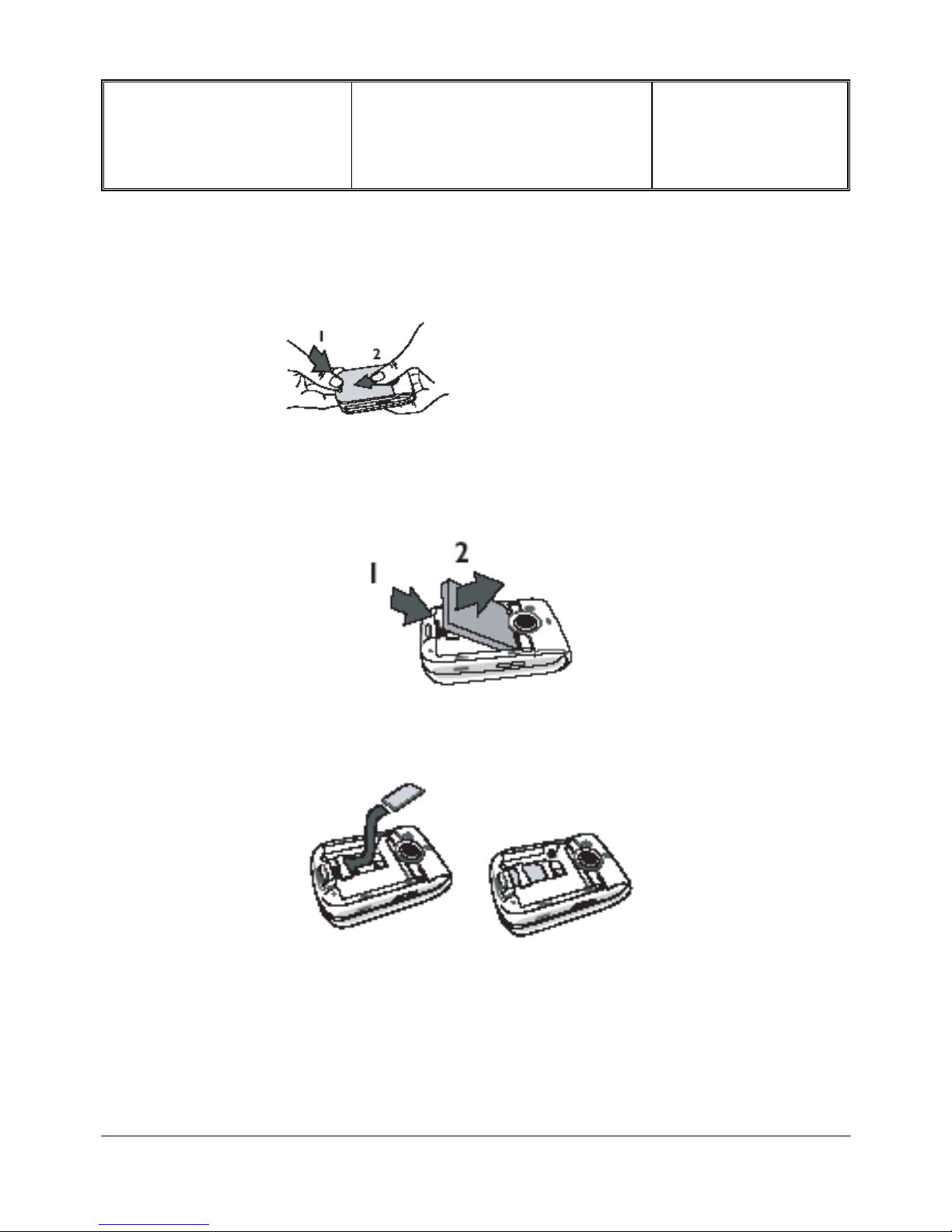
7.4 Remove Back Cover
Press on the back cover clip of the phone and slide the cover downwards to remove it.
7.5 Inserting The Sim Card
Remove the battery by lifting it with the grip as shown below.
Remove the SIM card from its holder and slide it in its slot until it stops. Be careful that the connectors are
facing downwards.
PHILIPS ELECTRONICS N.V. 1999 VY-V-640-P655
All rights reserved. Reproduction in whole
or in part is prohibited without the written
consent of the copyright owner.
Depart. Technical support- CM640 PROCEDURE COMPANY RESTRICTED
PHILIPS Consumer
Communications
Centre du Mans
Service Repair Support
VY-V-640-P655
Page : 12 of 74
Langue : EN
Date : 03/01/05
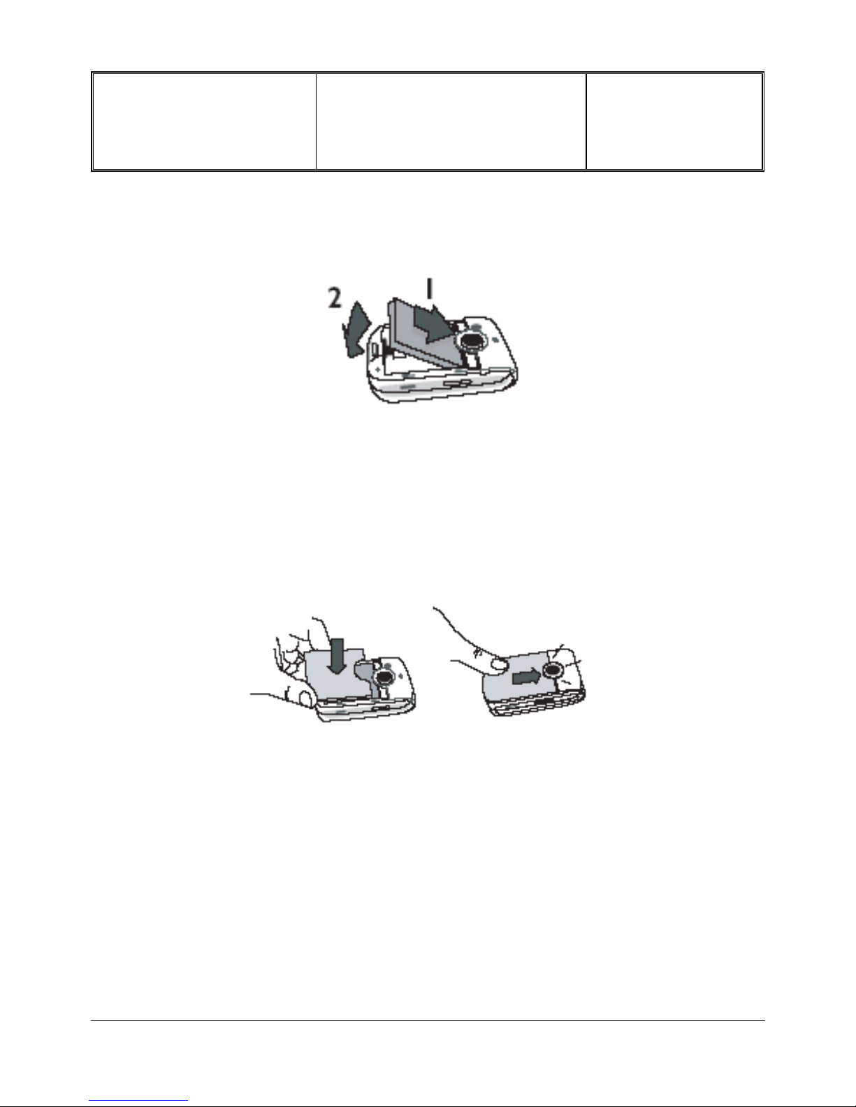
7.6 Inserting the Battery
Insert the battery by sliding it and pushing it downwards (connectors facing the connectors of the phone).
7.7 Replace Back Cover.
Replace the battery cover by sliding it into its slots, until it stops. Remove the protective film covering the
screen before using the phone.
PHILIPS ELECTRONICS N.V. 1999 VY-V-640-P655
All rights reserved. Reproduction in whole
or in part is prohibited without the written
consent of the copyright owner.
Depart. Technical support- CM640 PROCEDURE COMPANY RESTRICTED
PHILIPS Consumer
Communications
Centre du Mans
Service Repair Support
VY-V-640-P655
Page : 13 of 74
Langue : EN
Date : 03/01/05
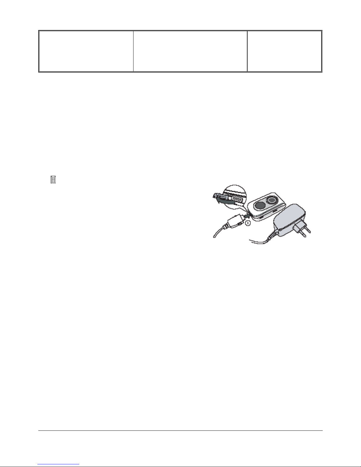
7.8 Charging The Battery
Phone is powered by a rechargeable battery. A new battery is partially charged and an alarm will warn you when
the battery reaches low. If the battery is completely flat,it will take 2 or 3 minutes of charging for its icon to
reappear.
Once the battery is clipped on the phone, plug the charger into the left hand socket at the base of the phone as
shown on the drawing.
Then plug the transformer unit into a main AC power
socket with easy access.
The symbol indicates the state of charge :
If the battery is completely flat, the battery icon will only
reappear after 2 or 3 minutes of charging.
During charging the 4 charge indicators change; each
bar represents around 25% of charge and it takes
around 1.45 hours to fully recharge your mobile phone.
Bars moving Battery is charging
Bars steady Battery is fully charged
Battery outline flashing (see troubleshooting chapter)
PHILIPS ELECTRONICS N.V. 1999 VY-V-640-P655
All rights reserved. Reproduction in whole
or in part is prohibited without the written
consent of the copyright owner.
Depart. Technical support- CM640 PROCEDURE COMPANY RESTRICTED
PHILIPS Consumer
Communications
Centre du Mans
Service Repair Support
VY-V-640-P655
Page : 14 of 74
Langue : EN
Date : 03/01/05
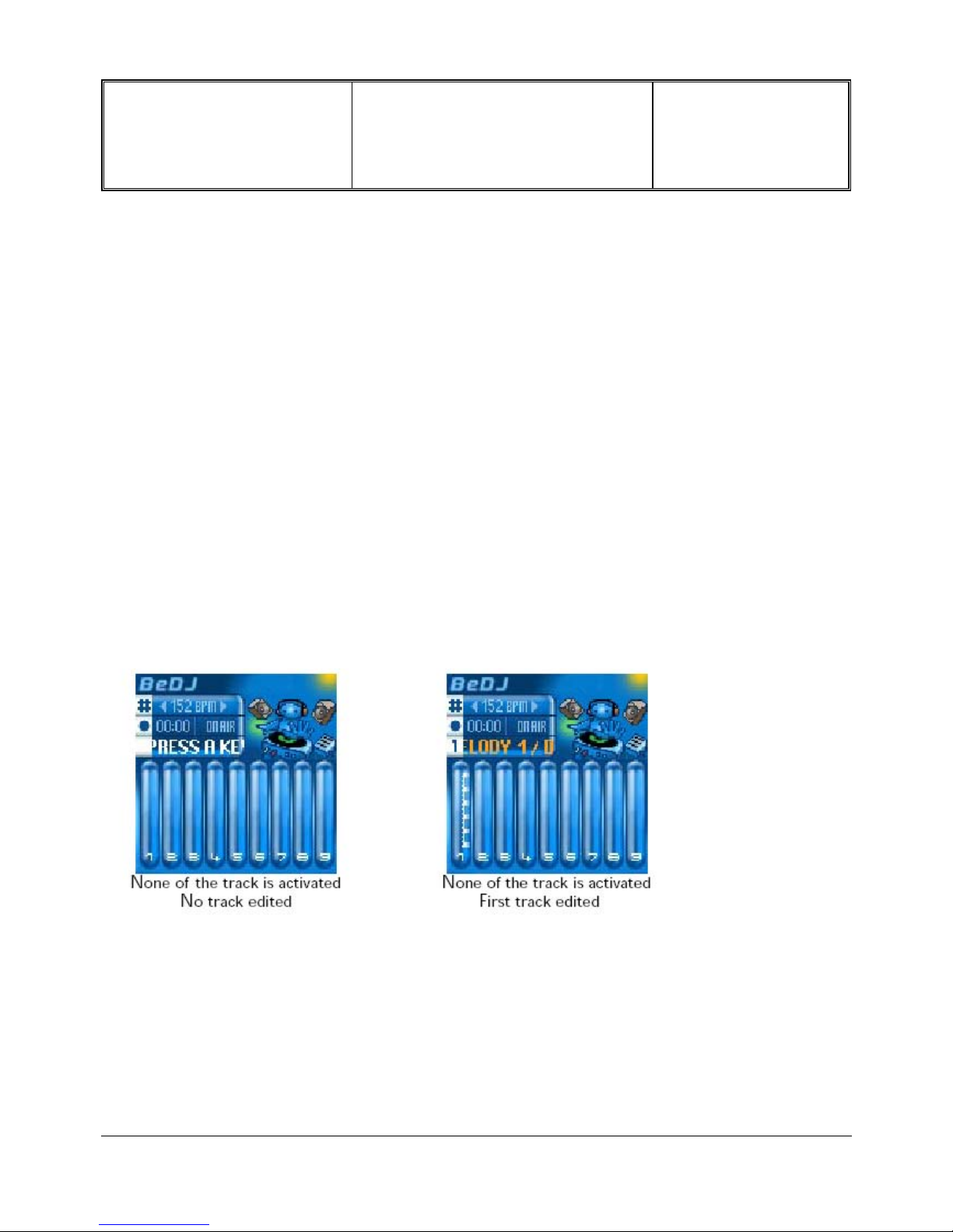
7.9 BeDJ Quick Presentation
The BeDJ feature is an innovative melody composer that let the user create and share electronic
music.
The user can create his sound using either a predefined BeDJ style, or any SP-MIDI or MIDI rings
tone that is already on the phone or was downloaded to the phone via MMS, Wap, or infrared.
The sharing experience relies on the possibility to send by MMS the mix that has just been created.
The user will be able to use it as well as Call alert and alarm tune, etc.
The 9 tracks displayed on the screen are linked respectively to a numeric key between 1 and 9 on
the keypad. The user can change the tracks selecting new tracks within the same BeDj style long
pressing the numeric key dedicated to the track he wants to change.
Above the tracks, a table shows, on the first line the current tempo value in bpm format, then on the
second line the status of the recording (off by default) and on the third line the name of the track
highlighted by the cursor. By default, none of the track is highlighted so the track area shows the
prompt “Press a key”. Moreover, on the left side of the table, the keys dedicated to the 3
information are indicated for direct access.
In the table and on the tracks, the orange colour is used to show the information currently in use.
For example, in the table, when the user presses the # key, the tempo value changes from the white
to the orange. Same principle when the user presses the 0 key to record a mix, the recording time
information changes from the white to the orange. Finally, when one of the track is highlighted by the
cursor, the track's volume and the track's name are shown in orange.
For More Information concerning BeDJ functions, please read user Guide.
PHILIPS ELECTRONICS N.V. 1999 VY-V-640-P655
All rights reserved. Reproduction in whole
or in part is prohibited without the written
consent of the copyright owner.
Depart. Technical support- CM640 PROCEDURE COMPANY RESTRICTED
PHILIPS Consumer
Communications
Centre du Mans
Service Repair Support
VY-V-640-P655
Page : 15 of 74
Langue : EN
Date : 03/01/05
7.10 Infrared Quick Presentation
Philips 655 integrates the infrared technology (also called IrDA), that allows to send or receive data to and
from other IrDA-compliant devices through a wireless link (e.g., another mobile phone, a PC or PDA, a printer etc.).
Instead of sending a message, you can decide to use IrDA to quickly send a sound or to receive pictures from
PDA.
You can also use your mobile phone together with a PC or a PDA, e.g. to surf the Internet or send faxes.
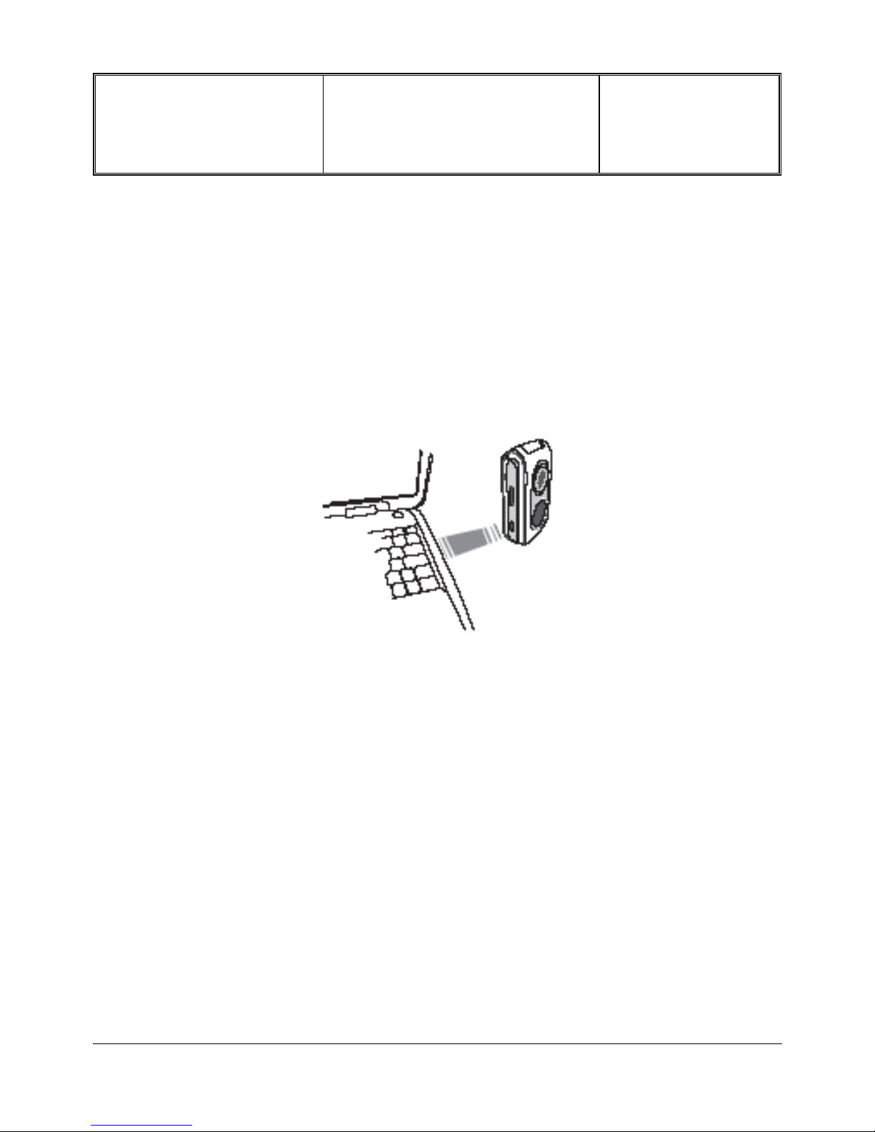
Before sending or receiving data to and from another device, they must be correctly positioned in relation to
your mobile phone. Make sure that the respective IrDA ports are facing each other and are a maximum
of 50 cm away from each other (see diagram). Also make sure that nothing obstructs the IrDA beam.
press “OK”, to send the selected data to the other device. For More Information concerning Infrared function,
please read user Guide.
PHILIPS ELECTRONICS N.V. 1999 VY-V-640-P655
All rights reserved. Reproduction in whole
or in part is prohibited without the written
consent of the copyright owner.
Depart. Technical support- CM640 PROCEDURE COMPANY RESTRICTED
PHILIPS Consumer
Communications
Centre du Mans
Service Repair Support
VY-V-640-P655
Page : 16 of 74
Langue : EN
Date : 03/01/05
7.11 MMS Quick Presentation
Your mobile phone allows you to send and receive MMS (multimedia messages), featuring texts, pictures
and sounds, including music mixes you have created with BeDJ or memos that you have recorded.
A multimedia message can be made of one slide (including text, sound and image), or of several: in this
case, the message is played in a slide show, whether you send it to an e-mail address or to another mobile
phone. For More Information concerning MMS function, please read user Guide.
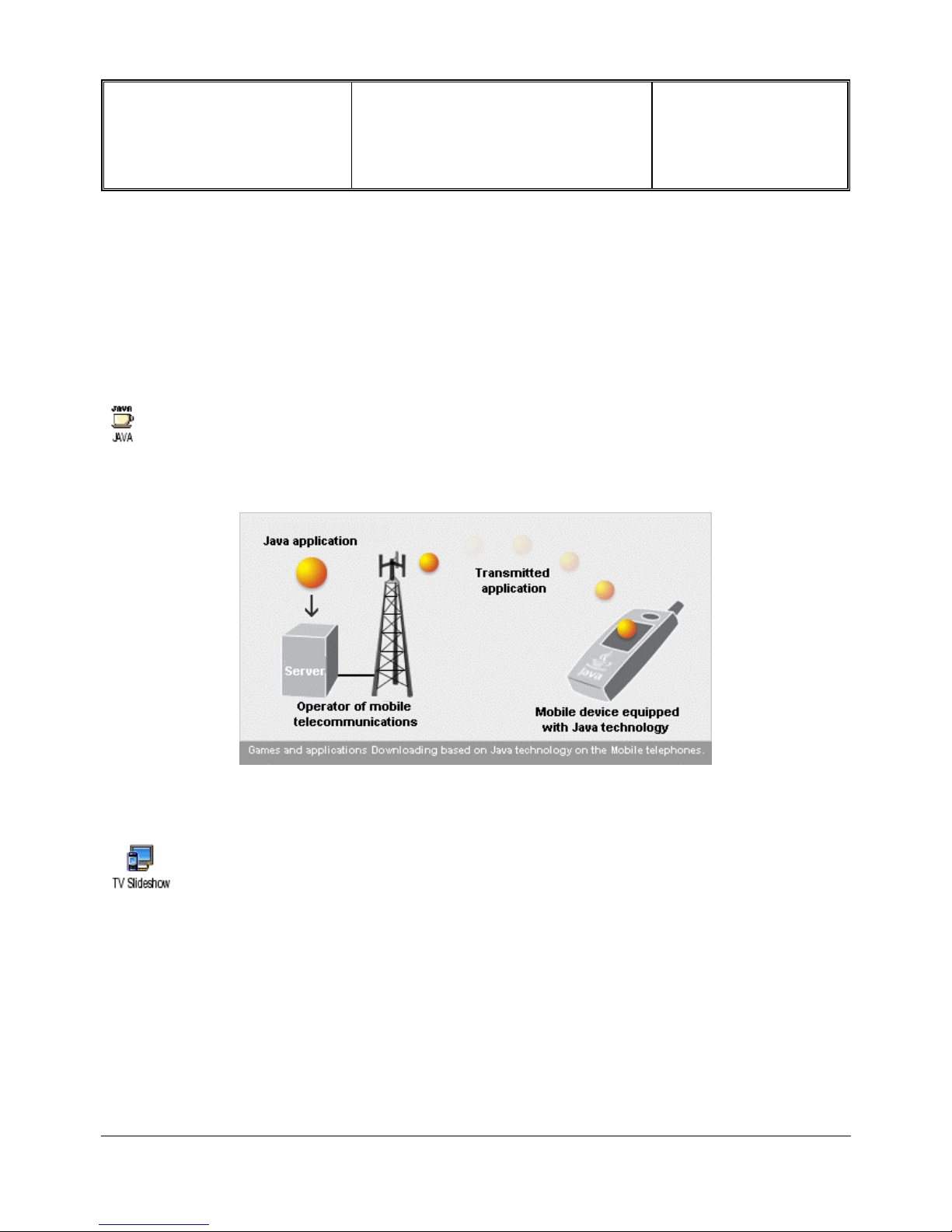
7.12 Java Quick Presentation
Philips 655 features JAVA, which allows you to run JAVA compatible applications. Java allows you to display a list
of applications, games and services, and to select most interesting. The application is then sent by radio
connection towards your Mobile, where it is installed and immediately usable.
For More Information concerning
Java function, please read user Guide.
7.13 TV Slideshow Quick Presentation
This feature allows you to display your JPEG pictures listed in the Picture album (automatically in a slideshow, or
manually, one-by-one) on a TV screen via the TV Link accessory or on the screen of your phone.
This data cable allows you to display a slide show on your TV. Simply connect the data end of the cable to the
headset (top) connector on the right hand side of your phone, then connect the video end to the video IN connector
of your TV or VCR.
For More Information concerning
TV Slideshow function, please read user Guide.
PHILIPS ELECTRONICS N.V. 1999 VY-V-640-P655
All rights reserved. Reproduction in whole
or in part is prohibited without the written
consent of the copyright owner.
Depart. Technical support- CM640 PROCEDURE COMPANY RESTRICTED
PHILIPS Consumer
Communications
Centre du Mans
Service Repair Support
VY-V-640-P655
Page : 17 of 74
Langue : EN
Date : 03/01/05
8.0 TEST PROCEDURES
8.1 Initial Functional check for PHILIPS 655
8.1.1 Insert the Test Production Card into the SIM reader at the back of the mobile phone and clip a charged
battery on the phone.
8.1.2 Press the “ON” button for 2 seconds at least and the LCD will show a message, which contains information
of FA (Final Adjustment) status and 12NC.
8.1.3 Follow the instructions as mentioned below:
Step Procedure Observation
1
Press Key 1
Press Key 1 again.
MANUAL TEST
GOOD
Left corner displays IDLE STATE
Key 0000
2
Press key 2
Press key 2 again
Camera Test (Allows to check camera
visualisation)
Left corner displays IDLE STATE
Key 0001
3
Press key 3
(Audio loop local effect)
Press key 3 again
"Audio Test
" Local”
" Audio Section”
“OK”
Left corner displays IDLE STATE
Key 0002
4
Press key 4
Press key 4 again
"LEDS TEST”
Check keypad Backlight
Left corner displays IDLE STATE
Key 0003
5
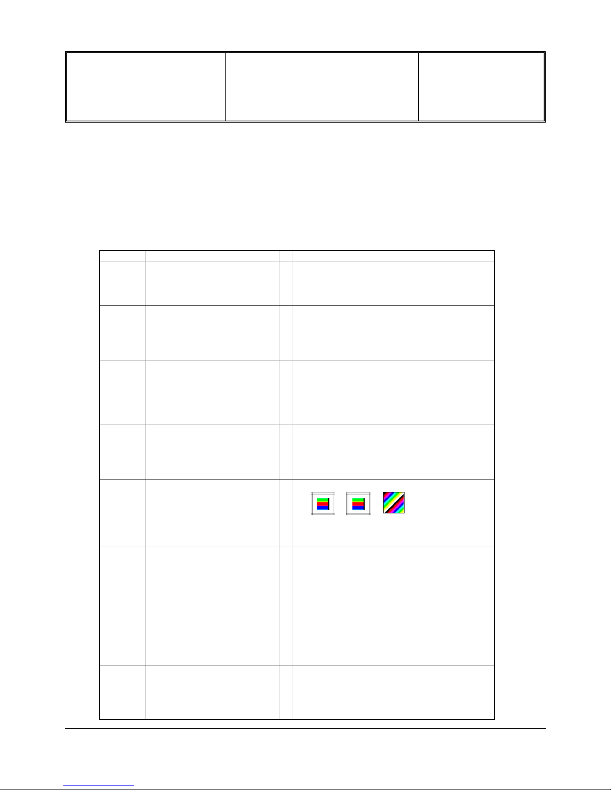
Press Key 5
(Checkerboard test) &
Backlight activation
Press Key 5 again
Checkerboard 1, 2 & 3 pixel on
Left corner displays IDLE STATE
Key 0004
6
Press Key 6
Clamshell Test
Press Key 6 again
"MAT CLAM SHELL TEST"
“OPENED”
Close clamshell to test Sub LCD
Checkerboard.
Left corner displays IDLE STATE
Key 0005
7
Press Key 7
Press key 7 again
"KEY WITHOUT TEST"
Left corner displays IDLE STATE
Key 0006
PHILIPS ELECTRONICS N.V. 1999 VY-V-640-P655
All rights reserved. Reproduction in whole
or in part is prohibited without the written
consent of the copyright owner.
Depart. Technical support- CM640 PROCEDURE COMPANY RESTRICTED
PHILIPS Consumer
Communications
Centre du Mans
Service Repair Support
VY-V-640-P655
Page : 18 of 74
Langue : EN
Date : 03/01/05
8
Press key 8 (Eeprom Status)
Press Key 8 again
"EEPROM STATUS”
00003000
00000000
Left corner displays IDLE STATE
Key 0007
9
Press Key 9 Product
information
Compare information with
label printed on back case
Press key 9 again
“PN: EOxxxxxx” (PN Number)
“0xXXXXXXXXXXXXXXXX” (Sw version)
“PCB:XX”
“DUT:XX”
VY made in Le Mans
SA made in Singapore
EO made in Shenzhen
Left corner displays IDLE STATE
Key 0008
10
Press key 0
Press key 0 again
" MELODY TEST "
User Melody should be heard and vibrations
felt.
Left corner displays IDLE STATE
Key 0009
11
Press *
Press * again
"MANUAL TEST BAD"
Left corner displays IDLE STATE
Key 0012
12
Press
Press Key again
"KEY WITHOUT TEST"
Left corner displays IDLE STATE
Key 0010
13
Press
Press Key again
"KEY WITHOUT TEST"
Left corner displays IDLE STATE
Key 000F
14
Press “MMS/ SMS” Key
Press Key again
"KEY WITHOUT TEST"
Left corner displays IDLE STATE
Key 001a
15
Press Key “BeDJ”
Press Key “BeDJ” again
"KEY WITHOUT TEST"
Left corner displays IDLE STATE
Key 0019
16
Press Key “OK “
Press Key “OK” again
" MELODY TEST "
User Melody should be heard and vibrations
felt.
Left corner displays IDLE STATE
Key 000e
PHILIPS ELECTRONICS N.V. 1999 VY-V-640-P655
All rights reserved. Reproduction in whole
or in part is prohibited without the written
consent of the copyright owner.

Depart. Technical support- CM640 PROCEDURE COMPANY RESTRICTED
PHILIPS Consumer
Communications
Centre du Mans
Service Repair Support
VY-V-640-P655
Page : 19 of 74
Langue : EN
Date : 03/01/05
17
Press “Left” Key
Press “Left” Key again
"KEY WITHOUT TEST"
Left corner displays IDLE STATE
Key 000c
18
Press “Right” Key
Press “Right” Key again
"KEY WITHOUT TEST"
Left corner displays IDLE STATE
Key 000d
19
Press “Up” Key
Press “Up” Key again
"KEY WITHOUT TEST"
Left corner displays IDLE STATE
Key 000a
20
Press “Down” Key
Press “Down” Key again
"MAT CLAM SHELL TEST"
“OPENED”
Left corner displays IDLE STATE
Key 000b
21
Press “C” Key
Press “C” Key again
"KEY WITHOUT TEST"
Left corner displays IDLE STATE
Key 001e
22
Press “Camera” Key
Press “Camera” Key again
"KEY WITHOUT TEST"
Left corner displays IDLE STATE
Key 001d
23
Press “+” Side Key
Press “+” Key again
"KEY WITHOUT TEST"
Left corner displays IDLE STATE
Key 0017
24
Press “-” Side Key
Press “-” Side Key again
"KEY WITHOUT TEST"
Left corner displays IDLE STATE
Key 0018
25
Press Key “ # ”
Press Key “ # ” again
" Enter page "
" to select
Left corner displays IDLE STATE
Key 0013
Advanced autotests (used generally for troubleshooting) :
Press “ # ” key to display “Enter page to select.”
PRESS Key "1" to change test page to "01", then press OK. (default test page is 00)
Key Functional test Observation
1
Press Key 1
Press Key 1 again
"AUDIO TEST"
“INTERNAL”
“Audio Section”
“OK”
Left corner displays IDLE STATE
Key 0000
PHILIPS ELECTRONICS N.V. 1999 VY-V-640-P655
All rights reserved. Reproduction in whole
or in part is prohibited without the written
consent of the copyright owner.

Depart. Technical support- CM640 PROCEDURE COMPANY RESTRICTED
PHILIPS Consumer
Communications
Centre du Mans
Service Repair Support
VY-V-640-P655
Page : 20 of 74
Langue : EN
Date : 03/01/05
2
Press Key 2
Press Key 2 again
"HandsFree"
“Test”
“Audio Section”
“OK”
You can check micro headset
Left corner displays IDLE STATE
Key 0001
3
Press Key 3
"Consumption" as Sleep mode
4
Press Key 4
Press Key 4 again
“ADC MEASURES”
“XXXX XXXX”
“XXXX XXXX”
Left corner displays IDLE STATE
Key 0003
5
Press Key 5
Press Key 5 again
"FLASH ID"
" XXXXXXXXX "
" RAM OK "
Left corner displays IDLE STATE
Key 0004
8.1.4 If any of these steps failed functional, please refer to Chapter 10.
8.1.5 Perform visual check on battery connectors, car kit connectors and casing. If corrosion or deform send to
NSC for repair.
8.1.6 If the product is good, it is considered as a NFF (No Fault Found) product.
All the NFF products must be directly returned to the customer.
PHILIPS ELECTRONICS N.V. 1999 VY-V-640-P655
All rights reserved. Reproduction in whole
or in part is prohibited without the written
consent of the copyright owner.

Depart. Technical support- CM640 PROCEDURE COMPANY RESTRICTED
PHILIPS Consumer
Communications
Centre du Mans
Service Repair Support
VY-V-640-P655
Page : 21 of 74
Langue : EN
Date : 03/01/05
8.2 RF Test
8.2.1 The Test SIM Card “SP” must be inserted in the phone before starting the tests.
8.2.2 Set the equipment as shown on the picture in chapter 6.2
8.2.3 Set RF losses.
8.2.4 The following operations must be done:
- Synchronization/Registration
- Call set up from the mobile
- Voice loopback ( to check the sound quality)
- Call release
- Call set up from tester
- Call release from tester
- GPRS attach
those two operations have to be added when the radio tester
- GPRS detach allows it
8.2.5 The following parameters must be checked in TCH loop mode :
Emission parameters :
- Power level
- RMS phase error
- Peak phase error
- Frequency error
- Power ramping
- Timing Advance
Reception parameters :
- Rx level
- Rx quality
- BER (Byte Error Rate)
- FER (Frame Error Rate)
- BLER (Block Error Rate)
(only when GPRS problems reported by the End User)
Generally the test sequences built inside the testers will be used to check the mobile. You must assess that the test
sequences limits comply with the standard specifications and defined test plan.
PHILIPS ELECTRONICS N.V. 1999 VY-V-640-P655
All rights reserved. Reproduction in whole
or in part is prohibited without the written
consent of the copyright owner.

Depart. Technical support- CM640 PROCEDURE COMPANY RESTRICTED
PHILIPS Consumer
Communications
Centre du Mans
Service Repair Support
VY-V-640-P655
Page : 22 of 74
Langue : EN
Date : 03/01/05
8.2.6 Radio test plan
Find below all the measurements that have to be done by test sequences.
Synchronization/Registration To be checked
Call set up from the mobile To be checked
Voice loopback ( to check the sound quality) To be checked
Call release To be checked
Call set up from tester To be checked
Call release from tester To be checked
GSM900-DCS1800 handover To be checked
DCS1800-PCS1900 handover To be checked
GPRS attach To be checked *
GPRS detach To be checked *
Power level Measurements
Power level
XXXXXX
RMS phase error X X X X X X
High level Peak phase error X X X X X X
Frequency error X X X X X X
Power ramping X X X X X X
Timing advance X X X
Power level
XXXXXX
RMS phase error
Mid level Peak phase error
Frequency error
Power ramping
Timing advance
Power level
XXXXXX
RMS phase error
Low Level Peak phase error
Frequency error
Power ramping X X X X X X
Timing advance
RF Level Measurements
Rx level X X X X X X
Rx qual
BER
(Byte Error Rate)
XXXXXX
FER (Frame Error Rate)
Rx level X X X X X X
Rx qual X X X X X X
BER
(Byte Error Rate)
XXXXXX
FER
(Frame Error Rate)
XXXXXX
BER Measurements on 104 frames = 8200 bits minimum
* Only if GPRS problems reported.
PCS Channels
Low Mid High
PCS Channels
Low Mid High
DCS Channels
High
TX measurements
GSM Channels DCS Channels
Low Mid High
Low Mid
Low Mid High
GSM Channels
Low Mid High
RX measurements
-102.0 dBm
-85.0 dBm
When using a wired test solution (via RF cable), don't forget that it is mandatory to measure the power
level radiated by the antenna (powermeter recommended). It is the only way to ensure good contact
between antenna and main board.
This warning doesn't apply when using an antenna coupler.
PHILIPS ELECTRONICS N.V. 1999 VY-V-640-P655
All rights reserved. Reproduction in whole
or in part is prohibited without the written
consent of the copyright owner.

Depart. Technical support- CM640 PROCEDURE COMPANY RESTRICTED
PHILIPS Consumer
Communications
Centre du Mans
Service Repair Support
VY-V-640-P655
Page : 23 of 74
Langue : EN
Date : 03/01/05
8.2.7 GSM Specification (900 Mhz)
Test parameter Channel Level Standard specifications
EMISSION
Phase Error RMS 1, 62, 124 5, 10, 15 0 to 5 degrees
Phase Error Peak 1, 62, 124 5, 10, 15 -20 to +20 degrees
Frequency Error 1, 62, 124 5, 10, 15 -90 Hz to +90 Hz
Power Ramping 1, 62, 124 5, 10, 15 Mask
Modulation 1, 62, 124 5, 10, 15 Mask
Switching Transients 1, 62, 124 5, 10, 15 Mask
Timing Advance 1, 62, 124 5, 10, 15 +/- 1.00 bit
Power Reading
Output Power Average 1, 62, 124 Level 19 5 +/- 5 dBm
1, 62, 124 Level 15 13 +/- 3 dBm
1, 62, 124 Level 10 23 +/- 2 dBm
1, 62, 124 Level 5 33 +/- 2 dBm
RECEPTION
Rx Level 1, 62, 124 -102 dBm 4 to 12
Rx Qual 0 to 1
Rx Level 1, 62, 124 -85 dBm 21 to 29
Rx Qual 0
Rx Level 1, 62, 124 -60 dBm 46 to 54
Rx Qual 0 to 0
TCH LOOP
SENSITIVITY
BER 1, 62, 124 -85 dBm 0%
FER 1, 62, 124 -85 dBm 0%
BER 1, 62, 124 -102 dBm < 2.44%
FER 1, 62, 124 -102 dBm 0%
If a phone is out of the specifications, it must be sent to the Repair Centre.
PHILIPS ELECTRONICS N.V. 1999 VY-V-640-P655
All rights reserved. Reproduction in whole
or in part is prohibited without the written
consent of the copyright owner.
 Loading...