


D
IGITAL
P
ROJECTION
T
ELEVISION
TABLE OF CONTENTS - QUICK USE GUIDE
• For details on product safety, registration,
warranty, and service refer to the other literature
included with your TV information packet.
Please retain all these materials and keep them
handy for future reference.
INTEGRATED
PRODUCT DESIGN
DPTV/NTSC/MONITOR
WARNING: TO PREVENT FIRE OR SHOCK
HAZARD DO NOT EXPOSE THIS UNIT TO
RAIN OR EXCESSIVE MOISTURE.
Getting Started
Warning/Precautions . . . . . . . . . . . . . . . . . .1
DPTV Integrated Product Design and Features
. .1
Basic DPTV and Remote Control Description
of Controls and Operations
. . . . . . . . . . . . . . . . .2-3
Digital (ATSC) Menu Control Operations
. . . . .4-5
Analog (NTSC) Menu Control Operations
. . . . . .6
Monitor Menu Control Operations
. . . . . . . . . . . .7
Digital TV Rollout - Time/Terms/& Technology
.8
NOTE: Not all features (and drawings) discussed in this
owner’s manual will necessarily match those found with
your television set. This is normal and does not require you
contacting your dealeror requesting service.
64PH9905 Digital Projection Television
TS1007 Pronto Remote Control
T
he Philips
64PH9905 Digital
Projection Television
(DPTV) represents an
advanced first step concept in integrated digital
products. Designed for
discrete and cross-over
system functionality the
64PH9905 will support
traditional NTSC
Television standards,
receive all certified FCC
defined ATSC digital
transmission formats, as
well as perform PC
Monitor Display capability.
Although future plans
allow for the two television broadcast systems
to coexist for a number
of years, the eagerly
awaited transition from
analog (NTSC) to digital (ATSC) high-definition television has
begun.
The Philips 64PH9905
DPTV is uniquely positioned to operate within
both current and future
video signal formats.
The Philips 64PH9905
will provide the largest
of viewing windows into
an unprecedented era of
high-definition picture
resolutions, digital surround sound playback,
and access to a variety
of entertainment and
interactive services.
P
lease refer to the rear
section of this Quick-
Use guide (page 8) for
additional information on:
• scheduled Digital
Broadcast program rollout dates, and what will
be available from the
various networks and
program suppliers
• the basics on how HDTV,
Digital, and Analog TV
systems differ and how
they can be received
• other ATSC (or Advanced
Television System
Committee) news and
details on digital broad
casting product operations and services
digital 1nf0rmation
• 64-Inch Rear Projection Television
Screen
• Audio Inputs - Stereo and 6-channel
Dolby Digital
• Subwoofer - for low frequency bass
surround sound
• Display formats - normal (overscan),
letterbox, or underscan
• Clock/Sleep Timer - set in NTSC analog system operational in ATSC as
well.
• Pronto Remote - set for both NTSC
and ATSC select feature operations
• Liquid Crystal Display - with large
backlit touchscreen for direct button
entry and key feature access
• Learn Capability - to learn and operate other infrared remote control product codes
• Customize - built-in device templates
for total product control
• Macro - editable programming for frequently used button sequences
• ATSC Formats - decodes all ATSC
digital system requirements as specified by FCC
• ATSC Broadcasts - tunes terrestrial
signal transmissions of major and subchannel digital programming
• PSIP Data - receives and processes
signal data for Program System
Information Protocol to display channel and program information
• Video Display - 1920 x 1080i resolu-
tion capability (4x3 ATSC video formats linearly stretched to fill 16:9 display)
• DTV Closed Captioning
• Dolby Digital Audio - for playback of
6-channel Dolby Digital audio material
• Alternate Audio - plays additional
audio tracks if available with ATSC
programming
• Freeze Video - holds video action
while audio continues (with time-out
feature to prevent possible screen burn)
• Autoprogram - for valid digital chan-
nels (with means of adding/deleting
specific stations from channel map)
• NTSC - reception of terrestrial broad-
cast NTSC signals
• Audio/Video Inputs - composite
Video or S-Video input connections
with accompanying Left/Right
2-channel audio
• Autoprogramming - for easy automat-
ic selection of favorite area stations
• Closed Captioning - to view program-
dialogue or voice conversation as onscreen text.
• Channel Labels - individual channel
call-letter/number editable titles
• Video Inputs: VGA and HD
• Audio Inputs: stereo and 6-channel
Dolby Digital
• Display formats: normal (overscan),
letterbox, or underscan
INTEGRATED FEATURES
PRONTO REMOTE FEATURES
DIGITAL (ATSC) FEATURES
ANALOG (NTSC) FEATURES
MONITOR FEATURES
1 - 3135 015 16081
TM
UP
CH
+
VOL
M
SOURCE
EXIT
VOL
–
CH
DOWN
ATSC CERTIFIED
DIGITAL TELEVISION

DVD
VIDEO INPUT
AUX3
VIDEO IN
L
AUDIO IN
R
DTV ANTENNA
DTV DIGITAL
AUDIO OUT
ANALOG
TV ANT/CABLE
AUX 1 AUX 2
S-VIDEO
ANALOG
AUDIO OUT
AUDIO INPUT
AUX 1 AUX 2
VIDEO OUT
VIDEO INPUT
L
R
L
R
SYSTEM AUDIO OUT
STEREO IN
6 CHANNEL
AUDIO IN
R
L
C
RS LS
SW
VGA IN
75 ohm
HIGH
SYNC
H/H + V
V
R/Pr
G/Y
B/Pb
HD COMPONENT
VIDEO IN
INTERNAL TV SPEAKERS
USED AS CENTER
CHANNEL
CENTER
CHANNEL INPUT
50 W MAX IN
– +
NO YES
SUBWOOFER
PREAMP OUT
FRONT
SPEAKERS
EXT INT
SUBWOOFER
SPEAKER OUT
– +
FRONT EXTERNAL SPEAKERS OUT
– +
– +
SURROUND EXTERNAL SPEAKERS OUT
– +
– +
All External Speakers 8 ohms Min.
R
L
R
L
AUDIO INPUT
FOR DVD,VGA,
OR HD
COMPONENTS
VIDEO S-VIDEO Pb Y Pr
SOURCE
EXIT
UP
CH
CH
DOWN
+
VOL
VOL
–
M
6
1
12:00
WXYZ
EXIT
SOURCE
UP
CH
CH
DOWN
+
VOL
VOL
–
M
3
2
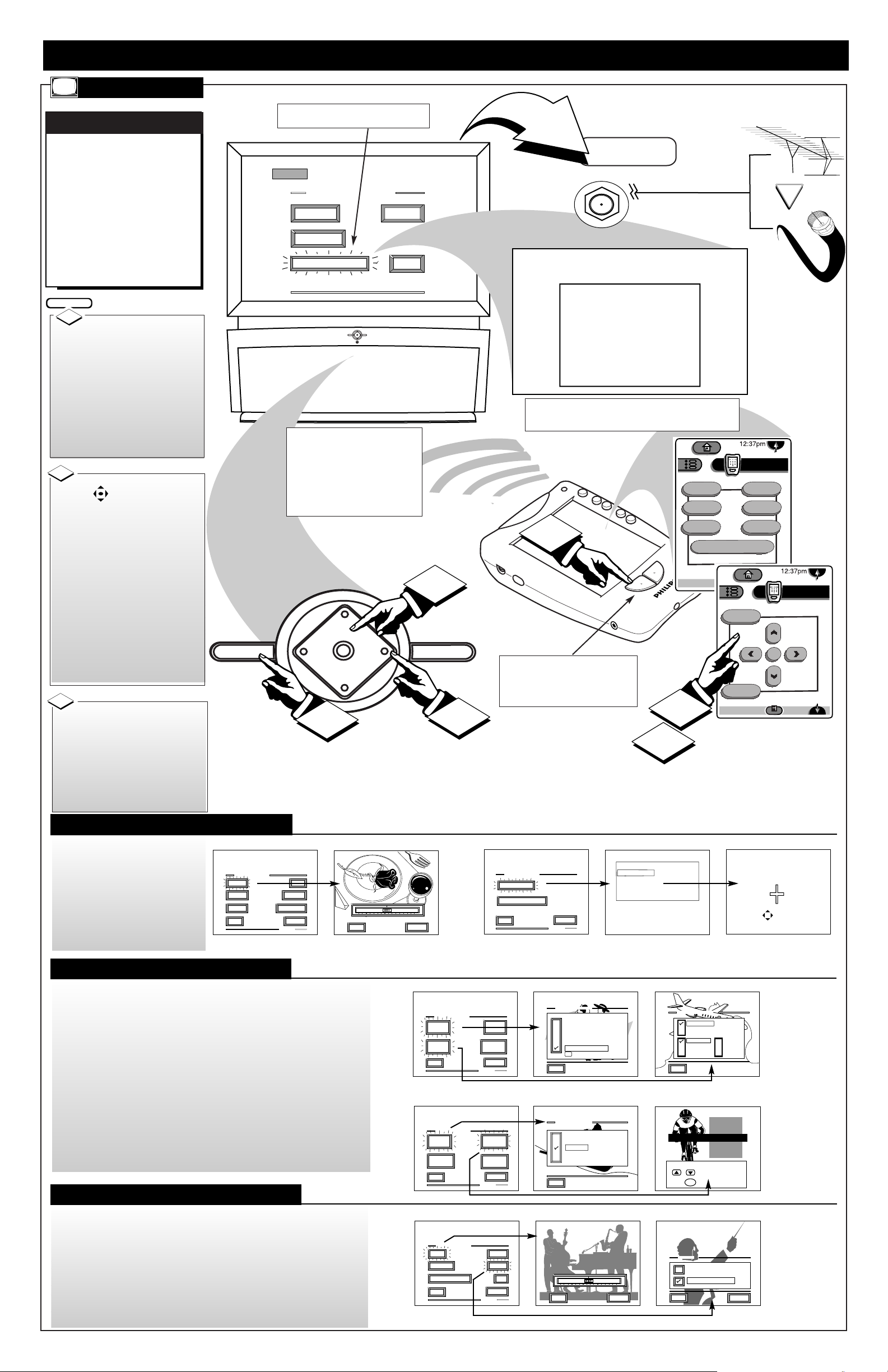
DPTV DESCRIPTION OF CONTROLS AND OPERATION
DPTV
Press the POWER
button to turn the DPTV ON.
(Green Power Light will display behind the ON button.)
Press the CHANNEL UP
or DOWN (▼) button to select
the desired TV channels.
3
1
STOP
2
D
igital Television
(DTV) will be av ailable to consumers
by ov er-the-air
broadcasts in select
city markets beginning in the fa ll of
1998. Homeowners
can use Indoor and
Outdoor Antennas to
receive the new
transmissions, but
like p revious NTSC
Analog programming
reception can be
e f fected by the type
and quality of the
antenna, and the terrain interf erence typical to certain areas.
See page 8 for D TV s
rollout plans, dates,
and schedules.
digital 1nf0rmation
• The DPTV can receive broadcasts from two antenna
sources. Connect an ATSC antenna to the DTV Antenna
jack, and a NTSC antenna, or cable TV signal, to the TV
Antenna/Cable jack.
• Multiple DVD signal connectors (Component-Y/Pb/Pr;
S-Video; or Composite) to be used for a variety of DVD
playback options. The DVD Inputs work in conjunction
with the DVD Stereo In audio jacks for sound playback.
• Three groups of NTSC Auxiliary Audio/Video Inputs can
be selected through the EXT INPUT button on the
remote, or the SOURCE button on the local keyboard.
• AUX1 - includes S-Video, CVBS Video, and accompany-
ing (Right)/(Left) channel Audio inputs.
Note: The AUX1 and AUX2 S-Video inputs work in conjunction with the AUX1 and AUX2 audio jacks for sound
playback.
• AUX2 - identical in operation to the AUX1 S-Video,
CVBS Video, (Right)/(Left) Audio Inputs.
• AUX3 - located on the right-side of the front of the
DPTV. Jacks include CVBS Video and (Right)/(Left)
Audio inputs.
• Two sets of A/V jacks direct external source signals to
the DPTV monitor:
• VGA IN - to connect a standard VGA (Video Graphics
Array) source for display.
• HD VIDEO IN - to input digital video from an external
source such as a computer. Input jacks include BNC connectors for R/Pr, G/Y, B/Pb, and H/H+ V signals.
• SYNC Switch - related to the HD Video inputs to allow
for synchronization switching between 75Ohm and High,
depending on the level of the digital source used.
• STEREO IN - jacks for (Right)/(Left) 2-channel stereo
sound to the DPTV speakers.
• 6-CHANNELAUDIO IN - to connect Right, Left,
Center, Right Surround (RS), Left Surround (LS), and
Subwoofer (SW) audio channels from an external Dolby
Digital device. The playback of 6-channel audio is also
dependent upon the configuration and adjustment of other
jackpanel (and ATSC Speaker Menu) switches and controls.
• The DPTV is capable of a variety of audio speaker configurations and connections for sending six channel audio
to internal and external speakers, as well as receiving
external supplied source material for playback.
• FRONT SPEAKERS Switch - to set the output of the
DPTV’s front (R)/(L)channel audio. INT(ernal) sends
(Right)/(Left) audio through the DPTV’s built-in (R)/(L)
front speaker system. EXT(ernal) routes the (R)/(L) channel audio to the FRONT EXTERNAL SPEAKERS OUT
terminals on the rear of the DPTV.
• FRONT EXTERNAL SPEAKERS OUT Terminals -
for the playback of the DPTV's front (Right/Left)
channel audio to external speakers (if connected). Note:
These speaker terminals are only active when the
FRONT SPEAKERS switch is set to EXT(ernal).
• SURROUND EXTERNAL SPEAKERS OUT
Terminals - to send the Surround Right (SR) and
Surround Left (SL) channel audio to external speakers.
• SUBWOOFER PREAMP OUT Jack - to send the
Subwoofer audio channel (at line level) to an external
powered Subwoofer speaker.
• SUBWOOFER SPEAKER OUT Terminals - to send
an amplified Subwoofer channel audio to an external
non-powered Subwoofer speaker.
• INTERNAL TV SPEAKERS USED AS CENTER
CHANNEL Switch -
used (in tandem with the Center
Channel Input switch - see next control description) to set
the DPTV’s built-in speaker system. Place the switch to
the YES position to use the DPTV for Center Channel
audio playback (as connected and supplied from an external Dolby Digital capable Amplifier source.) Place the
switch to the NO position to retain full DPTV internal
speaker system audio (with active Surround External
Speaker Out and Subwoofer Speaker Out terminal operation.)
Note: When the INTERNAL TV SPEAKERS and CENTER CHANNEL INPUT switches are placed in the YES
position no audio will be heard through the DPTV speaker system (unless a Dolby Digital capable Amplifier’s
Center Channel Output terminal is connected and active
through the DPTV’S CENTER CHANNEL INPUT terminals.)
• CENTER CHANNEL INPUT Switch - to control the
playback of the DPTV’s built-in speaker system for either
Center Channel audio (place switch to YES position
when connected to an external Dolby Digital capable
Amplifier’s Center Channel Output terminal); or for full
speaker DPTV system audio (place switch to NO in tandem with the Internal TV Speakers switch, see information listed above.)
• Three sets of audio output connectors and one video output connector are on the rear of the DPTV.
• SYSTEM AUDIO OUT - jacks send the DPTV system
audio (ATSC, NTSC, and Monitor) to an external amplifier. The DPTV outputs a 2-channel (Left/Right) stereo
audio signal.
• TV VIDEO OUT - CVBS video connector, matched
with a set of (Right/Left) Audio Outputs, used to send
NTSC video to an external source (such as a VCR, etc.)
• DTV DIGITAL AUDIO OUT - RCA connector which
routes the audio from the ATSC module to an external
amplifier/decoder that accepts a SPDIF (Sony-Philips
Digital Interface Format) input source.
Antenna/Cable Inputs (ATSC/NTSC)
A/V Inputs Monitor
Audio/Video Inputs (NTSC)
DVD Video Inputs
• Source - Press to cycle through
the DPTV available inputs (ATSC,
NTSC tuners and all external
inputs.)
• Menu (M) - Press to display the on-
screen control system for the
selected system. (See the ATSC,
NTSC, & Monitor sections for
details on the use and navigation
of the menus.)
• CH Up/Down - With a select Menu
system displayed, press to move
through the list of control features.
• VOL Up/Down - With a select
Menu system control displayed,
press to adjust the on-screen feature.
• Exit - Press to display a Status
screen for the selected Menu system, or clear the screen following
Menu feature adjustments.
Rear DPTV Jackpanel
Infrared Remote Sensor Window
Side Cabinet Jackpanel
(located on Right/Front
side of DPTV)
Press the VOLUME (+)
UP or VOLUME (-) DOWN
button to adjust the sound level.
2
Audio Speaker Switches/Connectors
Audio/Video Outputs
DPTV LOCAL KEYBOARD FUNCTIONS
BEGIN

PRONTO REMOTE DESCRIPTION OF CONTROLS AND OPERATION
TS1007 (LCD)
To install the four
supplied AA batteries:
Slide the battery cover off the
back of the Pronto remote.
Reattach the battery
cover when completed. The
Pronto should now be ready for
use.
3
1
STOP
IR Transmitter
(Sending Eye)
Insert (4-AA) batteries
into the battery compartment.
Be sure the (+) and (-) ends of
the batteries line up correctly
(inside of case is marked.)
An optional recharging
dock and rechargeable bat-
tery pack are also available
for the Pronto remote.
A light on the front of the
Battery Dock will indicate
when the batteries are fully
charged. Depending upon the
condition of the battery pack
a complete recharge could
take 2-3 hours.
BATTERY RECHARGING
Light Sensor
- Direct Access Buttons -
• The Mute, Channel (+,-), and Volume (+,-) buttons
will operate even when the LCD touchscreen is off.
They can also be programmed to operate a dedicated
component, such as the DPTV, or different devices at
different times.
LCD Touchscreen
- Left/Right Buttons -
• Function of the Left and Right buttons change depend
ing on the device the Pronto is controlling.
• The LCD touchscreen display will show the Left and
Right buttons current control function labels.
Learning Eye
Contrast Dial (+,-)
Backlight Button
Serial Port
(for future upgrades)
Battery Cover
INTELLIGENT REMOTE
T
he PRONTO
TS1007 is a LCD
touchscreen universal,
learn remote that combines flexibility of use
with maximum adaptability. Set to automatically work with your
Philips 64PH9905
DPTV and all its integrated Menu system features, the Pronto also
has preset “Device”
operations for a variety
of Audio and Video
accessory products
(such as VCR, DVD,
CD, Tape, etc.)
Although the Pronto
remote’s preprogrammed operating
codes (RC5/6) were set
to work with Philips and
Marantz branded products, other manufacturer’s equipment can easily be controlled through
the Pronto’s “Learn”
mode capability. Even
the Pronto’s keypress
buttons and Device
select list can be customized or rearranged
to better match the
order and commands
for your specific inhome electronics.
The Pronto can also
memorize select key button sequences in order
to automate, or “shortcut”, a feature function
selection or process.
Once created and placed
in memory the recorded
“macros” will execute
the desired commands
to the various components in order to complete, for example, a
VCR movie playback on
the DPTV or other similar procedure.
Due to the amount of
optional components
available within the
Pronto’s Device
Reference and Learn
Code Lists, please refer
to the separate full-use
Pronto Owner’s Manual
for complete details on
its functions and operations.
Rechargeable Battery Pack and Dock
- Battery Life Note -
• Use only AA alkaline or lithium batteries for best results.
• Never mix worn and fresh batteries.
• When battery power is running low a Low Battery icon blinks at
the top of the Pronto LCD display.
• Certain features may continue to operate when battery power is
low, but you won’t be able to use the Pronto’s learn or customizing
features.
Battery Compartment
Recharging Contacts
To turn the Pronto
display screen ON, touch the
screen with your finger, then let
go.
Pressing the Backlight button
(on the left side of the remote)
also turns the display ON.
Turn the Contrast dial (on the
left side of the remote) to
adjust the screen’s brightness.
BEGIN
1
• Tap the touchscreen gently when
using the Pronto. Never use force.
• Do not use pens, or any sharp
object to tap the screen. You might
damage the surface.
• Keep the touchscreen dry. Wipe
off any spills immediately. Never
immerse the Pronto in water or any
liquid.
• Do not drop the Pronto on hard
surfaces (or drop anything on the
LCD touchscreen itself.)
• Do not expose the Pronto to
extreme temperatures.
• Clean the touchscreen with a soft
cloth (dampened slightly if needed.)
Never use abrasives or cleaning
solutions.
The Pronto will display
the last device screen used (or
the Home screen for all of the
devices the Pronto is set to
operate.)
Press the Home button
at any time to return to the
Pronto’s components menu list.
2
Press the button for the
desired device to display a
control panel screen for the
device.
Home Screen
Control Panel
A Device menu can also
be used to select components
from a currently opened control screen.
Press the Device
tab on the touch-
screen and a Device
list will appear. Just
tap the name of the
device you want to operate.
You can also scroll the Device
list by pressing the Arrow button to move down or
up the list.
3
Press a button on the
control panel to send a remote
command to the selected
“active” device.
Use the scroll
arrows
to move to the next
(or previous) page
of controls. The touchscreen
will display the current control
screen’s page number, and the
total number of pages available
for the device (1/8; 2/8; etc.)
4
The Pronto is ready to
send device commands when
the Pronto icon is shown
(at the center top of the touchscreen display.)
If another mode label is covering the Pronto icon, such as
or , the mode
will need to be reselected.
Tap the Mode
button on the touchscreen, and reselect
the mode to
return the Pronto to
its normal operating mode.
5
STOP
2
Side View
CONTROLS
OPERATIONS
3
TOUCHSCREEN USE/CARE
BEGIN
TV
DTV
VCR
Pre Amp
Tuner
DBS
CD
LD
DVD
Tape
CDR
INFO
A/CH1/1

DIGITAL (ATSC) MENU CONTROL OPERATIONS
A
lthough the visual pre-
sentation and display for
each of the three independent
on-screen Menu systems
(ATSC, NTSC, Monitor) differ to help identify which
mode the DPTV is in, the
overall highlight/selection/
and adjustment operations
for each of the Menus will be
consistent, or have the same
on-screen “feel.”
Use the Pronto remote’s
touchscreen “DTV” device
menu (page 3/3), or the
DPTV’s local keyboard, to
access and select controls
within each of the three
DPTV Menu systems.
DPTV CONTROLS
ATSC MENUS
With the Pronto’s DTV
device touchscreen selected,
press the “DTV” command but-
ton (located on the lower right
of the Pronto’s case - see illustration) to select the ATSC on
screen feature Menu controls for
the DPTV.
You can also press the
SOURCE button on the
DPTV’s local keyboard to select
the ATSC Menu mode.
BEGIN
1
Press the Scroll Arrows on
the Pronto’s touchscreen to
select the DTV Menu (page 3/3)
cursor screen to operate the
DPTV’s Main Menu. Then press
the “menu” or “ok” button on
the touchscreen to display the
DTV Main Menu.
If using the DPTV’s local keyboard, press the M(enu) button
to display the DTV MAIN
MENU.
2
Press the Left/Right §©
direction Arrows on the Pronto
to adjust the selected on-screen
feature control.
If using the DPTV’s local keyboard, press the the VOL(ume)
+,- buttons to adjust the feature.
Press the “exit” button on
the Pronto (or the DPTV’s local
keyboard) to clear the screen
after an adjustment.
The screen can also be cleared
by selecting the Main Menu's
"Exit" item and pressing the
MENU (M) button. Waiting
about a minute, without a button
press, will also remove the
MENU from the screen.
4
Press the Up/Down ▲▼
Arrows on the Pronto touch-
screen to highlight items within
the DTV Main Menu features’
list. Press the “menu” (or “ok”
button) on the touchscreen to
select the specific highlighted
Main Menu feature.
If using the DPTV’s local keyboard, press the CH(annel)
UP/DOWN buttons to highlight
the Main Menu features. Then
press the M(enu) button to
select the highlighted feature.
3
STOP
5
ON THE DPTV
ON THE PRONTO
SELECTED ATSC FEATURE CONTROL
HIGHLIGHTED WITHIN MENU
Select BACK and then
press M(enu) button to
return to previous Menu
screens.
4
ADDITIONAL PRONTO DPTV FUNCTIONS
• ALTERNATE AUDIO - Press to cycle
through any audio language tracks available
with a current DTV program. If alternate
audio is found, the DPTV will play the
selected alternate soundtrack and display its
language as an on-screen indicator.
• SLEEP - Press to set the amount of time
before the DPTV will automatically turn
itself OFF (15 minute - 2 hour settings).
• DTV FREEZE - Press to freeze current
TV action on the DPTV screen. Press the
Freeze button again (or wait approximately
one minute without a button press) to return
the DPTV to live action. Audio will continue to play while the picture is frozen. A
freeze picture indicator will appear onscreen.
• EXTERNAL INPUT - Press to cycle
through the Analog NTSC Auxiliary Inputs
(AUX1/2/3); and other possible External
Monitor connection inputs (EXT HD, DVD
VGA, etc.). The DPTV will display the
name of the selected input in the corner of
the DPTV screen.
• ANALOG FORMAT - Press to select the
Analog NTSC tuning mode on the DPTV.
Remote transmitter commands will be
directed to the “normal” analog TV menu
system control features.
3
4
Note: Press the Left (Analog) or Right
(DTV) command button on the Pronto to
select which on screen Menu system the
remote is to send its control commands
(either NTSC/Analog or ATSC/DTV).
1
ATSC
DTV Main Menu
Picture
Sound
Speakers
Features
Tuning Program
DTV Setup
Exit
UP
CH
+
VOL
M
SOURCE
EXIT
VOL
–
CH
DOWN
Picture Menu
Color
Brightness
Sharpness
Picture
Tint
Convergence
Back
1
1
SOURCE
4
3
2
UP
CH
VOL
–
DOWN
+
M
VOL
CH
EXIT
5
power
alt audio
sleep
analog format
Analog
DTV
status
freeze
ext input
DTV1/3
menu
exit
Analog
2
ok
2
DTV
DTV
menu
ok
DTV3/3
exit
Analog
DTV3/3
menu
exit
Analog
ok
DTV3/3
DTV
5

f
i
v
e
t
i
m
e
s
m
o
r
e
p
i
c
t
u
r
e
i
n
f
o
r
m
a
t
i
o
n
(
p
i
x
e
l
s
)
a
s
N
T
S
C
T
V
n
o
p
i
c
u
t
r
e
g
h
o
s
t
s
o
r
s
n
o
w
a
s
d
e
l
i
v
e
r
e
d
b
y
b
r
o
a
d
c
a
s
t
a
n
d
s
a
t
e
l
l
i
t
e
d
o
l
b
y
d
i
g
i
t
a
l
s
u
r
r
o
u
n
d
s
o
u
n
d
5
.
1
d
i
s
c
r
e
t
e
c
h
a
n
n
e
l
s
t
w
i
c
e
t
h
e
v
e
r
t
i
c
a
l
p
i
c
t
u
r
e
r
e
s
o
l
u
t
i
o
n
(
7
2
0
p
o
r
1
0
8
0
i
)
o
f
a
n
a
l
o
g
T
V
w
i
d
e
s
c
r
e
e
n
a
s
p
e
c
t
r
a
t
i
o
1
6
:
9
DIGITAL (ATSC) MENU CONTROL OPERATIONS (CONTINUED)
T
he “DTV Setup” menu
automatically takes care
of some of the digital channel
scan memory functions for
the DPTV. Once connected to
receive local digital broadcast
transmissions, available area
stations can be quickly added
into the DPTV's channel
memory for programmed
channel selection or access.
AUTOPROGRAM CHANNELS
ATSC MENUS
5
Initial Digital broad casts will be av ailable through Overthe-Air signal,
Direct-Satellite
transmission, and
on some Cable TV
operator systems.
Route the DTV signal connection to
the DTV Antenna
plug on the rear of
the DPTV. See page
8 for further
details.
digital 1nf0rmation
PICTURE MENU FUNCTIONS
• Select to adjust separate Color
and Picture controls on the
DPTV. When the slide bar scales
are centered, control settings are
at normal mid-range levels.
• Use the Convergence control to
line up the Red and Blue light
paths for the DPTV screen.
DTV ANTENNA
SOURCE EXIT
UP
CH
CH
DOWN
+
VOL
VOL
–
M
ATSC
DTV Main Menu
Picture
Sound
Speakers
Features
Tuning Program
DTV Setup
Exit
Would you like to program DTV channels?
This process may take several minutes.
Yes, full installation
No
Yes, add new channels
DTV Setup
Auto Program
Autoprogramming in progress.
This may take several minutes.
Cancel
Installing
- Digital Channel Selection Delay -
• Due to the tuning complexity of “subchannel” digital
programming (see explanation section to the left), the
time to select and view a digital channel may take
slightly longer than what the viewer is normally accustomed to (as compared to Analog channel programs.)
Digital channel broadcasts contain program and system
data information that also must be processed before the
channel selection can be displayed.
Analog vs. Digital Antenna Signals
(Strength and Direction Traits)
• Existing analog broadcast signals experience
increasing picture snow/ghosts/or interference as
the transmitted signal travels further from the
original broadcasting tower. The farther out you
move the reception point, the more the broadcast
signal degrades or grows weaker.
• Digital broadcast reception maintains a clearer,
more interference free picture throughout its
broadcast range, but once the limit of its broadcast range is reached the picture will quickly
drop from the screen (rather than a slower picture quality degrade as is the case with analog
reception.)
- DTV Antenna Reception -
• Contact your dealer for the best
DTV Antenna reception options
available for your area.
Both Indoor and Outdoor omnidirectional UHF/VHF antennas
can be used to receive digital
broadcast signals, but seek your
dealer’s expert advice for the best
in quality equipment to match
your DPTV.
Alternate Audio preference: English
06.01 Source 1 No title available
Rear of DPTV
Picture Menu
Color
Brightness
Sharpness
Picture
Tint
Convergence
Back
SPEAKER MENU FUNCTIONS
• Select the various Speaker
Menu
controls to setup the configuration of the DPTV’s six
speaker system for Dolby Digital
audio playback. Each trim control
can be adjusted to match test tone
levels, or customized to match
current listening room arrangements.
Speaker Menu
Center Delay
Front Left
Right
Rear On/Off
Left
Right
Delay
Test Tone
Subwoofer Level
Back
Front in Line
On
15 feet or more
Off
SOUND MENU FUNCTIONS
• Select Surround Mode
to direct and process
Dolby Digital audio
through the DPTV
6-speaker sound system.
(Stereo redirects Left and
Right channel stereo
playback without Dolby
ProLogic processing.)
• Use Auto Volume to con-
trol the variable amount
of peak compression for
Dolby Digital audio available with ATSC broadcasts. This can make for
even, more consistent
sound between program
changes, etc.
Sound Menu
Surround Mode
Treble
Bass
Auto Volume
Back
Surround
Day time listening
FEATURES MENU FUNCTIONS
• Select and adjust for Closed
Caption mode settings and dis-
play options.
• Use the Add/Delete Channel
control to add (or delete) digital
channel numbers from the
DPTV’s program scan memory.
• Use Parental Control to block
out or censor unwanted channels.
Add/Delete Channel
Add This Major Channel
Delete This Major Channel
Back
Features Menu
Captions Format
Captions On/Off
Add/Delete Channel
Parental Control
Back
Caption 1
Always On
Note: The new standards (for
bandwidth and signal compression) employed with digital ATSC broadcasting make
it possible to receive multiple
program channels under a
single “major” channel number. For example, under a traditional channel “6” broadcast program number you
might be able to find as many
as four or more additional
programs available for selection. These so called “subchannels” might carry a
“06.01, 06.02, 06.03, etc.” type
station number designation
and could be selected by
pressing a four digit remote
control direct-access channel
number entry.
The multiplication and diversity of sub-channel programming is contingent upon the
decisions of broadcasters and
how the space allocated for
high-definition television signals might be used. The content and information available
with sub-channels will be an
evolving digital issue which
could experience redirection
on a number of multicasting
information technology pathways. For example, the
“squeezing” of numerous
Standard Definition digital
channels (SDTV) into signal
bandwidths could be used
rather than dedicating the
total signal spectrum to true
High Definition (HDTV)
broadcasts that would rival
the picture resolution and
quality of film or cinema.
SUBCHANNEL SELECTIONS
• Note: Program and System Info or
(PSIP) is carried automatically within
the digital signal for program broadcasts
available in your area. PSIP contains the
signal encoding necessary for the
reception of digital audio processing, as
well as the new Parental Content
Advisory system for movies and TV
programming.
CONVERGENCE MENU
ALIGN RED
ALIGN BLUE
CONVERGE MULTI POINT
BACK
SOURCE
EXIT
UP
CH
CH
DOWN
+
VOL
VOL
–
M
FEATURES
EXIT
ANALOG MAIN MENU
SOUNDPICTURE
1ST TIME SETUP
SOURCE
UP
CH
CH
DOWN
+
VOL
VOL
–
M
NTSC
2
3
The First-Time Setup
provides a simple method
of adjusting the most
important controls for
this television receiver.
Press "M" To Continue
ANALOG
TV ANT/CABLE
EXIT
1
ANALOG (NTSC) MENU CONTROL OPERATIONS
O
perating in the same
manner as other DPTV
integrated product Menus
(ATSC, Monitor), highlight
the desired on-screen control and press the M(enu)
button on the Pronto
remote, or DPTV local keyboard, to select the Analog
NTSC feature for use.
ANALOG TV CONTROLS
NTSC MENUS
SELECTED NTSC FEATURE CONTROL
HIGHLIGHTED IN RED
• Use EXIT on the Pronto touchscreen,
or the DPTV local keyboard, to remove
the Menu from the screen.
• You can also select and highlight
EXIT within the Menu, then press
the Menu button to drop on-screen
controls, or wait approximately a
minute and the screen will automatically time out and disappear.
PICTURE MENU FUNCTIONS
• Select to adjust separate Color
and Picture controls within the
Analog NTSC Menu. When the
slide bar scales are centered, control settings are at normal midrange levels.
• Use the Convergence control to
line up the Red and Blue light
paths for the DPTV screen.
PICTURE MENU
SHARP
PICTURE
CLEARVIEW
EXIT
1 OF 2
COLOR TINT
MORE...
BRIGHT
EXIT
NEXT...
MIN
MAX
COLOR
SOUND MENU FUNCTIONS
• Use the Bass, Treble, and Balance
controls to adjust the sound playback for the NTSC mode audio.
• Select Stereo to switch between
monaural (mono) and two channel
stereo broadcast material.
• Use SAP (Second Audio
Program) to receive separate
audio channel simulcast program
information (when available.)
• Use the AVL (Automatic Volume
Limiter) control to preset the
desired volume level for program
viewing. This can maintain a con
sistent sound transition between
program changes, commercial
breaks, etc.
• Use the Display Volume control
to see DPTV’s volume levels on
the DPTV screen.
FEATURES MENU FUNCTIONS
• Note: Certain Feature Menu
tasks, such as Program Channel
Memory and Cable Tuning, are
automatically completed for you
as part of “First Time Setup.”
• Select and adjust Closed
Captions for Caption and Text
mode display options.
• Use the Add/Delete Channel
control to add, or drop, individual channel numbers from the
program scan memory.
• Use Smart Picture to set individual “preferences” in the setup
and use of select control features.
• Channel Labels enable the view-
er to choose from a “preset” list
of station callouts (or manually
create specific station titles.)
• Display Format resets the
DPTV’s screen for various aspect
ratio and image format styles.
• Channel Display controls the
size and style of the DPTV’s
on-screen status displays.
• Use Parental Control to block
out or censor unwanted channels.
• Set Clock to enter the current
time for the DPTV’s clock.
FEATURE MENU
EXIT
2 OF 3
DISPLAY
FORMAT
MORE...
CHANNEL
LABELS
CHANNEL
DISPLAY
to EXIT
CHOOSE ANTENNA CHANNEL
M
to SELECT LABEL
BRV
CBN
CNBC
CMT
Channel 1 0
CBS
PARENTAL
CONTROL
EXIT
PANORAMIC
4 X 3
16 X 9
THEATER 1
THEATER 2
DISPLAY FORMAT
Cable TV Signal
Combination VHF/UHF
Antenna
OR
Use the Analog NTSC “First Time Setup” menu to program
channels into the DPTV’s scan memory, set screen convergence,
and access the TV Smart Clock feature for initial setup operation.
2
3
1
Press the “Analog”
command button (located on the
lower left of the Pronto’s case see illustration on this page) to
select the NTSC on screen
Menu controls for the DPTV.
You can also press the
SOURCE button on the
DPTV’s local keyboard to select
the NTSC Menu mode.
BEGIN
1
Press the Left/Right §©
Arrows on the Pronto to adjust
the selected on-screen feature
control.
If using the DPTV’s local keyboard, press the the
VOL(ume) +,- buttons to adjust
the feature.
Press the direction
Arrows on the Pronto’s TV
touchscreen (page 3/3) to highlight items within the Main
Menu features’ list. Press the
“menu” (or ok” button) on the
touchscreen to select the specific
highlighted control.
If using the DPTV’s local keyboard, press the CH(annel)
UP/DOWN and VOL(ume) +/-
buttons to highlight the Main
Menu features. Then press the
M(enu) button to select the highlighted feature.
3
2
6
CONVERGENCE MENU
ALIGN RED
ALIGN BLUE
CONVERGE MULTI POINT
BACK
PRESS TO ALIGN RED
PRESS MENU TO RETURN
PICTURE MENU
EXIT
2 OF 2
MORE...
CONVERGENCE
VIDEO ENHANCEMENT
Color and Picture Menu Control Adjustments
Convergence Menu Control Adjustments
EXIT
LABEL 1
LABEL 2
LABEL 3
LABEL 4
LABEL 5
FACTORY SETTINGS
M to SELECT
SMART PICTURE
FEATURE MENU
EXIT
1 OF 3
SMART
PICTURE
MORE...
CABLE
TUNING
CLOSED
CAPTION
CHANNEL
MEMORY
CABLE TUNING
EXIT
ALWAYS ON
ALWAYS OFF
ON DURING MUTE ONLY
CAPTION 1
CAPTION 2
CAPTION 3
CAPTION 4
TEXT 1
TEXT 2
TEXT 3
TEXT 4
CLOSED CAPTION
Feature Menu Control Adjustments
EXIT
NEXT...
MIN
MAX
BASS
SOUND MENU
DISPLAY VOLUME
STEREO
AVL
EXIT
1 OF 2
BASS TREBLE
MORE...
BALANCE
STEREO
EXIT
MONO AT ALL TIMES
STEREO IF AVAILABLE
NEXT...
Sound Menu Control Adjustments
Rear of DPTV
Note: Press the Left (Analog) or Right
(DTV) command button on the Pronto to
select which on screen Menu system the
remote is to send its control commands
(either NTSC/Analog or ATSC/DTV).
power
alt audio
sleep
analog format
Analog
DTV
status
freeze
ext input
DTV1/3
menu
ok
exit
Analog
DTV
DTV3/3

SOURCE
EXIT
UP
CH
CH
DOWN
+
VOL
VOL
–
M
VGA IN
75 ohm
HIGH
SYNC
H/H + V
V
R/Pr
G/Y
B/Pb
HD COMPONENT
VIDEO IN
INTERNAL TV SPEAKERS
USED AS CENTER
CHANNEL
CENTER
CHANNEL INPUT
50 W MAX IN
– +
NO YES
SUBWOOFER
PREAMP OUT
FRONT
SPEAKERS
EXT INT
SUBWOOFER
SPEAKER OUT
– +
FRONT EXTERNAL SPEAKERS OUT
– +
– +
SURROUND EXTERNAL SPEAKERS OUT
– +
– +
All External Speakers 8 ohms Min.
R
L
R
L
BRIGHTNESS
PICTURE
SHARPNESS
COLOR
TINT
BACK
HD
SVGA
VGA
SOURCE
UP
CH
CH
DOWN
+
VOL
VOL
–
M
2
3
EXIT
1
MONITOR MENU CONTROL OPERATIONS
O
perating in the same
manner as other
DPTV integrated product
Menus (ATSC, NTSC),
highlight the desired onscreen control and press the
M(enu) button on the
Pronto remote, or DPTV
local keyboard, to select
the Monitor display feature
for use.
MONITOR DISPLAY CONTROLS
MONITOR MENUS
SELECTED MONITOR FEATURE CONTROL
HIGHLIGHTED WITHIN MENU
• BNC (Bayonet Connectors) are available
to attach a computer to the DPTV for use
as a monitor display. The optional BNC
cables twist and secure to the individual
Red/Green/Blue and Horizontal/Vertical
Sync(hronization) component Video
Inputs on the rear of the DPTV. This type
connection ensures optimum video and
color reproduction performance from a
computer, or other external High
Definition playback source.
MONITOR MENU FUNCTIONS
• Note: Certain barscale Monitor
Feature Menu adjustments (such
as Brightness, Picture, etc.) will
display separate control panel
screens for individual settings.
Repress the Menu button (on the
Pronto remote or local keyboard)
to return the DPTV to the
Monitor Feature Menu when control adjustments are complete.
• Use the Brightness and other
Monitor picture features (such as
Picture, Sharpness, etc.) to adjust
overall DPTV screen intensity for
optimum light/dark screen areas
and shading details.
• Turn the Volume Barcontrol
ON to display the volume level
settings for external audio
sourced material on the DPTV
screen.
• Select the Bass/Treble/Balance
controls to adjust low/high fre-
quency sound and speaker
balance for external input audio
source material played through
the DPTV’s audio system.
• Use the Display Mode and
Format controls to set the DPTV
for the type of external monitor
input source (VGA, SVGA, HD);
and the DPTV’s display screen
format for use (PC, Normal).
Rear of Computer
2
3
1
Press the “ext input”
button on the Pronto’s TV
touchscreen, or SOURCE on the
local keyboard, to place the
DPTV in the desired monitor
display mode (VGA, SVGA,
EXTHD).
BEGIN
1
Press the Left/Right §©
Arrows on the Pronto to adjust
the selected on-screen feature
control.
If using the DPTV’s local keyboard, press the the
VOL(ume) +,- buttons to adjust
the feature.
Press the Up/Down ▲▼
Arrows on the Pronto’s TV
touchscreen (page 4/4) to highlight items within the Monitor
controls’ list. Press the “menu”
(or “M” button) on the touchscreen to select the specific
highlighted feature.
If using the DPTV’s local keyboard, press the CH(annel)
UP/DOWN buttons to highlight
the Monitor Menu features.
Then press the M(enu) button to
select the highlighted feature.
3
2
7
Rear of DPTV
• A VGA (Video Graphics Array) IN(put)
plug is also provided on the rear of the DPTV
to complete a standard connection with a
computer for monitor display purposes.
BNC Cables
(optional)
PICTURE
SOUND
FEATURE
EXIT
BRIGHTNESS
PICTURE
SHARPNESS
COLOR
TINT
BACK
AUDIO INPUT STEREO BACK
VOLUME BAR ON
INTERNAL AMP ON
BASS
TREBLE
BALANCE
BACK
DISPLAY MODE VGA
DISPLAY FORMAT NORMAL
INPUT TYPE RGB
SYNC TYPE AUTO
HOR PHASE
BP WIDTH
BACK
BRIGHTNESS
MAIN MENU
• Note: The list of Monitor Menu features (and
their individual control settings) will change
or readjust according to the capabilities of
the selected Display Mode (VGA, SVGA, etc.)
Monitor Main Menu
Control Adjustments
Picture Menu Controls
Sound Menu Controls
Feature Menu Controls
power
alt audio
sleep
analog format
Analog
DTV
status
freeze
ext input
DTV1/3
DTV
menu
ok
exit
Analog
DTV3/3

DIGITAL TV ROLLOUT - TIME/TERMS/TECHNOLOGY
T
he switch to digital pro-
gramming won’t happen
overnight, but broadcasters are
beginning the task of converting equipment and production
capabilities to meet the FCC’s
rules for signal format and
launch of digital TV.
The first step for the networks
will be to supply their affiliates
with one satellite program feed
for continuing NTSC service (at
least thru the year 2006), and
another feed for a single channel of HDTV (or SDTV format
channels). ABC, CBS, NBC,
and PBS networks are all
attempting to broadcast some
HDTV programming beginning
in the fall of 1998 (see the digital InfOrmation section to the
right for specific plans and
details), but much in the way of
new digital broadcast tower construction, site zoning and other
conversion issues will need to be
resolved in order for the broadcasts to begin in earnest.
In the beginning local stations
can offer different programming on their allotted digital
channel space, but as time passes the percentage of NTSC programs that must be converted to
digital “simulcast” broadcasts
will increase (in order to meet
specified conversion schedule
requirements.)
The Cable TV industry’s standard for the use and carrying of
digital broadcasts, which has a
different frequency modulation
than cable signals, is unresolved
(as of the date of this publication.) Although some cable
operators promise that digital
set-top boxes or decoders will be
available to pass HDTV signals
to digital TV sets, no official
“must carry” design for the
interfacing of cable TV programming and digital TV technologies has been agreed upon.
Even without firm program
launch dates or established
guidelines, digital cable decoder
equipment and program offering plans (by such cable program providers as HBO, Turner
Broadcasting and the Discovery
Channel) are all underway for
the interconnection of cable TV
and the arrival of HDTV. It may
not have immediate solutions at
the outset, but market and
industry demands should speed
cable operators to provide for
the HDTV signal to make it into
the cable supplied home.
Direct-broadcast satellite system
(DSS) providers (such as Direc
Tv, Unity Motion, Dish
Network, etc.) have also
announced plans to deliver
HDTV to its customer base in
the spring of 1999. DSS subscribers will likely need upgraded dish and satellite receiver
designed equipment to complete
their digital reception package,
but a number of providers are
working on both off-the-air signal and direct satellite feed solutions.
PROGRAM AVAILABILITY
DTV TIMETABLE
While they may differ on the choice
of digital f ormats
(1080i, 720p, 480i,
etc.) the netw orks
broadcast plans
center mainly on
select primetime *
program viewing.
Because of the
production techniques and equipment upgrades
necessary for digi tal broadcasts the
telecasting of
sports or other
live e v ents will not
become available
until audience view ership can justify
costs.
Some initial netw ork plans fo r digi tal broadcasts:
ABC- Wonderful
W orld of Disney (in
720p format); to
phase in other
HDTV broadcasts
later.
CBS- proposed to
send five hours of
1080i programming
per week
NBC- to begin
shooting The
T onight Show with
Jay Leno in HDTV
beginning in 1999;
also plans to show
other primetime
show s in HDTV
Fox to distribute
some portion of its
schedule in 720p
HDTV.
*Outside of the
primetime slot for
net w ork digital
sho w s local sta tions can provide
diff erent programming on their digital
broadcast channel.
They are free to
convert current
NTSC programming
into digital SDTV or
even upgrade their
signal to true HDTV.
ABC, NBC and Fox
are advising affili ates to use 480p
f or the majority of
its broadcast day,
while CBS recommends its stations
use the 480i fo rmat.
digital 1nf0rmation
TOP TEN MARKETS (30% OF US HOUSEHOLDS)
TOP 30 MARKETS (50% OF US HOUSEHOLDS
• Baltimore
• Charlotte
• Cincinnati
• Cleveland
• Denver
• Hartford/New Haven
• Houston
• Indianapolis
• Miami
• Minneapolis/St. Paul
• Orlando
• Phoenix
• Pittsburgh
• Portland
• Raleigh/Durham
• Sacramento
• San Diego
• Seattle/Tacoma
• St. Louis
• Tampa/St. Petersburg
• By November 1999
• By November 1998
(Voluntary)
• By May 1999
(Mandatory)
• Atlanta
• Boston
• Chicago
• Dallas
• Detroit
• Los Angeles
• New York
• Philadelphia
• San Francisco
• Washington, D.C.
• High Definition Television (HDTV) is approxi-
mately twice the vertical and horizontal resolution of today’s NTSC TV. Because of the extra
width (16:9) format of HDTV the picture contains about five times as much information (or
pixels) as conventional TV.
HDTV also includes 5.1 channels of Dolby
Digital surround sound to be broadcast through
two front speakers; one center speaker; two rear
back speakers; and a separate bass channel or
subwoofer signal.
• HDTV refers to the product/system with the following minimum performance specs:
- Resolution: vertical display resolution of
720P, 1080I, or higher
- Aspect Ratio: capable of displaying 16:9 for-
mat images at the minimum resolution levels
- Audio: receives, reproduces, and/or outputs
Dolby digital audio
- Receiver: receives all ATSC (Table 3) formats
• Standard Definition Television (SDTV) offers
about the same picture resolution as today’s
NTSC TV, but the picture quality is improved
because of the lack of snow and ghosts that
accompany normal NTSC over-the-air broadcasting.
Multiple channels are possible with SDTV since
the 6-MHz signal space allotted for digital
broadcasts can be used for other types of less
data filled format programming.
• Standard Definition Television (SDTV) refers to
the product/system with the following performance attributes:
- Resolution: display resolution lower than that
of HDTV
- Aspect Ratio: none specified
- Audio: produces useable audio
- Receiver: receives all ATSC (Table 3) formats
and produces a useable picture
all other commercial stations must construct digital facilities by May 2002
(non-commercial stations, such as PBS affiliates, by May 2003)
Digital Television
Format/Name
Screen/Image
Aspect Ratio
(width to height)
Horizontal
Resolution
(pixels across screen
width)
Vertical
Resolution
(Viewable Scan
Lines)
High Definition TV
HDTV 1080P/1080I
High Definition TV
HDTV 720P/720I
Total Pixels
(transmitted per
video frame*)
Standard Definition
TV (SDTV)525P/525I
1920
16:9 2,073,600
16:9
4:3 - 16:9
Standard Definition
TV (SDTV)
ADVANCED TELEVISION SYSTEM COMMITTEE FORMATS
PROGRESSIVE (P) AND INTERLACE (I) SCAN
• Progressive and Interlace refer
to the method in which the video
from a picture telecast is scanned
or displayed on the TV screen.
-
Interlace scans or paints half
the vertical lines for the picture
on the screen every 1/60 of a
second. Then the rest of the picture is filled in between the lines
of the first half on a followup
scan. The speed of this process
is so fast that it appears to the
eye as being one complete picture. Due to the amount of infor-
mation contained in a 1080-line
HD picture, interlace is needed
to fit the format into the allotted
6MHz channel space.
-Progressive scans or paints the
entire video picture one line
after another. Used with today’s
computer monitors this progressive process can eliminate some
of the picture artifacts found
with interlace scan, but does
require a larger bandwidth in
order to deliver programs at the
same frame rate.
4:3
1280
704
640
1080
720
480
480
921,600
337,920
307,200
8
FREQUENTLYASKED DTV QUESTIONS
Q: What are the goals of DTV?
A: In the United States the commitment for free and local digital
broadcasts is a main standard for the
new ATSC system. The reception
and interaction of local terrestrial
broadcasting for DTV programming
is to remain the same regardless of
the region or area of the country in
which you reside.
Q: How long will the transition to
DTV take?
A: The move to digital programming will shift from initial select
program offerings; to increased
simulcast availability; to the ultimate return of analog NTSC broadcast channels to the federal government in 2006. The NTSC and ATSC
systems will coexist for years to
come (with possible date extensions
provided for the return of NTSC
system channels if needed.)
Products such as the 64PH9905
DPTV are uniquely positioned with
operation capability matched for
both the NTSC and ATSC systems.
Q: What’s in the future for DTV?
A: Because of the computer, multimedia, and broadcast services
involved in setting ATSC and signal
compression standards, DTV picture
formats can be universally adopted
not only for TV broadcasts but also
for computer and other interrelated
web and network service purposes.
Digital Television (DTV) is the umbrella term used to describe the new digital television system adopted by the FCC. DTV is an open standard with few specific format rules for the implementation of
HDTV/SDTV/and a host of potential data broadcast applications. Although there are certain guidelines
for frequency/bit rates/transmission power/etc. the FCC has taken the position that the marketplace
should decide or dictate what formats will best serve the public.
The interlace scan process was first used with
NTSC broadcasts to conserve video bandwidth
space. With certain scenes or video material
the interlace process can cause image blurring
or other visual screen artifacts.
INTERLACE FIELDS
(Separate scans sent every 1/60 of a second)
*60 frames per second
(fps) for live video; 24
and 30 fps for material
produced in film.
FOR BROADCAST
 Loading...