

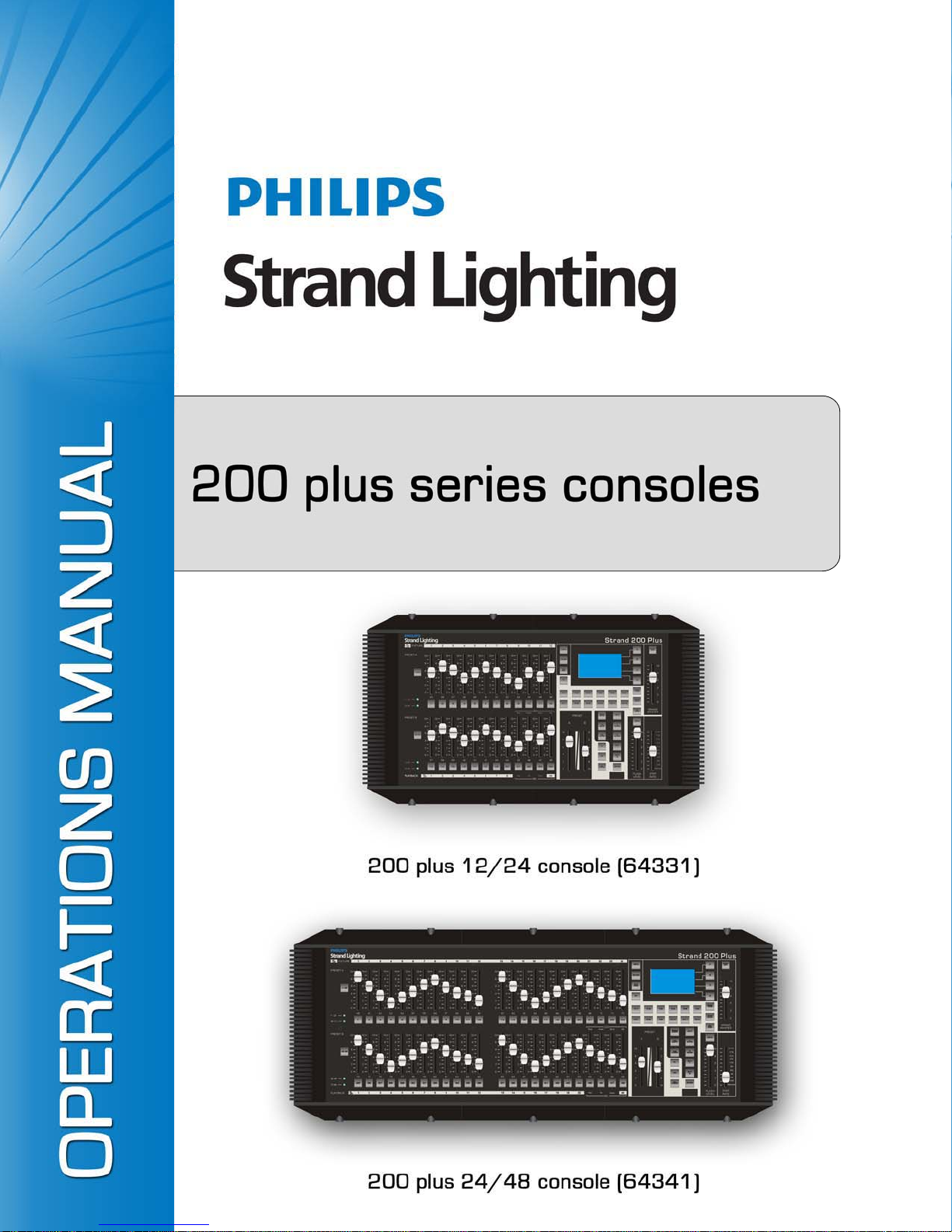
Philips 64331, 64341 Operation Manual

Strand Lighting Offices
Philips Strand Lighting - Dallas
10911 Petal Stree t
Dallas, TX 75238
Tel: 214-647-7880
Fax: 214-647-8031
Philips Strand Lighting - Auckland
19-21 Kawana Street
Northcote, Auckland 0627
New Zealand
Tel: +64 9 481 0100
Fax: +64 9 481 0101
Philips Strand Lighting - Asia Limited
Unit C, 14/F, Roxy Industrial Centre
No. 41-49 Kwai Cheong Road
Kwai Chung, N.T., Hong Kong
Tel: +852 2796 9786
Fax: +852 2798 6545
The material in this manual is for information purposes only and is subject to change without notice. Philips Strand
Lighting assumes no responsibility for any errors or omissions which may appear in this manual. For comments and
suggestions regarding corrections and/or updates to this manual, please visit the Philips Strand Lighting web site at
www.strandlighting.com or contact your nearest Philips Strand Lighting office.
El contenido de este manual es solamente para información y está sujeto a cambios sin previo aviso. Philips Strand
Lighting no asume responsabilidad por errores o omisiones que puedan aparecer. Cualquier comentario, sugerencia
o corrección con respecto a este manual, favor de dirijirlo a la oficina de Philips Strand Lighting más cercana.
Der Inhalt dieses Handbuches ist nur für Informationszwecke gedacht, Aenderungen sind vorbehalten. Philips
Strand Lighting uebernimmt keine Verantwortung für Fehler oder Irrtuemer, die in diesem Handbuch auftreten. Für
Bemerkungen und Verbesserungsvorschlaege oder Vorschlaege in Bezug auf Korrekturen und/oder
Aktualisierungen in diesem Handbuch, moechten wir Sie bitten, Kontakt mit der naechsten Philips Strand Lighting
Niederlassung aufzunehmen.
Le matériel décrit dans ce manuel est pour information seulement et est sujet à changements sans préavis. La
compagnie Philips Strand Lighting n'assume aucune responsibilité sur toute erreur ou ommission inscrite dans ce
manuel. Pour tous commentaires ou suggestions concernant des corrections et/ou les mises à jour de ce manuel,
veuillez s'il vous plait contacter le bureau de Philips Strand Lighting le plus proche.
Philips Strand Lighting - Europe
Rondweg zuid 85
Winterswijk 7102 JD
The Netherlands
Tel: +31 (0) 543-54 2516
Website:
www.strandlighting.com
Note: Information contained in this document may not be duplicated in full or in part by any person without prior written
approval of Philips Strand Lighting. Its sole purpose is to provide the user with conceptual information on the equipment
mentioned. The use of this document for all other purposes is specifically prohibited.
Document Number: STR-64331 Rev. C
Version as of: 14 October 2013
200 Plus Series Console Operations Manual
©2011 - 2013 Philips Group. All rights reserved.
IMPORTANT INFORMATION
Warnings and Notices
When using electrical equipment, basic safety precautions should always be followed including the following:
a. READ AND FOLLOW ALL SAFETY INSTRUCTIONS.
b. Do not use outdoors.
c. Do not use near gas or electric heaters.
d. The use of accessory equipment not recommended by the manufacturer may cause an unsafe
condition.
e. Do not use this equipment for other than intended use.
f. Refer service to qualified personnel.
SAVE THESE INSTRUCTIONS.
WARNING: You must have access to a main circuit breaker or other power disconnect device before installing
any wiring. Be sure that power is disconnected by removing fuses or turning the main circuit breaker off before
installation. Installing the device with power on may expose you to dangerous voltages and damage the device.
A qualified electrician must perform this installation.
200 Plus Series Console
WARNING: Do not open the console. There are no user serviceable parts inside. This equipment is designed to
operate from the mains electrical supply and contains voltages, which, if touched, may cause death or injury. It
should only be operated in accordance with the instructions provided and for the purpose of a lighting control
system.
WARNING: Avoid spilling liquid on the equipment If this should happen, switch the equipment off
immediately at the mains. To reduce the risk of fire or electric shock, do not expose the equipment to rain or
moisture. For indoor use only.
WARNING: Refer to National Electrical Code® and local codes for proper use specifications.
WARNING: This equipment is intended for use in accordance with the National Electric Code® and local
regulations. It is also intended for installation in indoor applications only. Before any electrical work is
performed, disconnect power at the circuit breaker or remove the fuse to avoid shock or damage to the control.
It is recommended that a qualified electrician perform this installation.
Additional Resources for DMX512
For more information on installing DMX512 control systems, the following publication is available for purchase
from the United States Institute for Theatre Technology (USITT), "Recommended Practice for DMX512: A Guide
for Users and Installers, 2nd edition" (ISBN: 9780955703522). USITT Contact Information:
USITT
315 South Crouse Avenue, Suite 200
Syracuse, NY 13210-1844 USA
1-800-938-7488 or +1-315-463-6463
www.usitt.org
Philips Strand Lighting Limited Two-Year Warranty
Philips Strand Lighting offers a two-year limited warranty of its products against defects in materials or
workmanship from the date of delivery. A copy of Philips Strand Lighting two-year limited warranty containing
specific terms and conditions can be obtained from the Philips Strand Lighting web site at www.strandlighting.com
or by contacting your local Philips Strand Lighting office.
1

Operations Manual
TABLE OF CONTENTS
Strand Lighting Offices....................................................................................................... Inside Front Cover
IMPORTANT INFORMATION
Warnings and Notices............................... ....................................... ................................................................ 1
Additional Resources for DMX512................................... ........................................ ...................................... 1
Philips Strand Lighting Limited Two-Year Warranty..................................................................................... 1
TABLE OF CONTENTS
PREFACE
About this Guide..................................................................................................................................................... 4
Product Descriptions............................................................................................................................................... 4
Compliance Information......................................................................................................................................... 4
Included Items ..................................................................... ....................................... ............................................ 4
INTRODUCTION
200 Plus Series Console Layout............................................................................................................................. 5
12/24 Version .................................................................................................................................................. 5
24/48 Version .................................................................................................................................................. 6
Glossary of Terms................................................................................................................................................... 7
Getting Started...................................... ....................................... ........................................................................... 8
Site Requirements............................................................................................................................................ 8
Console Rear Panel Connections and Controls............................................................................................... 9
Connecting Power ........................................................................................................................................... 9
Connecting DMX512 .................................................................................................................................... 10
Video Monitor Connection................................................................................................................................... 11
Product Care ......................................................................................................................................................... 11
Customer Service and Support ............................................................................................................................. 11
CONSOLE BASIC OPERATION
Two Scene Control ............................................. ....................................... ..................................... ...................... 12
Entering Two Scene Operation Mode................................................................................................... ........ 12
Timed Operation................................................................................. ........................................................... 14
Flashing Channels ...................................................................... ....................................... ............................ 15
Single Scene Operation.................................... ....................................... .............................................................. 15
Entering Single Scene Operation Mode........................................................................................................ 16
Setting a Scene .............................................................................................................................................. 16
Timed Fades ................. ....................................... ........................................ .................................... .............. 17
Submaster Operation ............................................................................................................................................ 18
Recording a Submaster.................. ....................................... ......................................................................... 18
Playing Back a Submaster............................................................................................................................. 18
Playing Back a Submaster with Time ...................................................................................................... ..... 18
Changing Submaster Pages .................................................................................................. ... ...................... 19
Playing Back Submasters Sequentially......................................................................................................... 20
Using Time to Playback Submasters Sequentially ........................................................................................ 21
Deleting Submasters.......................................................................................................... ............................ 22
CONSOLE ADVANCED OPERATION
Moving Light (ML) Mode.................................................................................................................................... 24
Setting Up Moving Lights............................................................................................................................. 24
Using your Moving Lights ....................... ............................................................................... . ..................... 26
Further ML Functions available in the Menu Function................................................................................. 34
List ML............................................................................................................................................ .............. 35
Auto DMX..................................................................................................................................................... 35
P/T Invert.......................................................... ............................................................................................. 35
2 TABLE OF CONTENTS

200 Plus Series Console
Memory Lock.............................. ........................................ ....................................... ................................... 35
LED Mode................................................................................................................. ....................................... .... 36
Setting up LED Lights........................................................................................................... ........................ 36
Programming LEDs....................................................................................................................................... 38
Further ML Functions available in the Menu Setting ................................................................................... 45
List LED........................................................................................................................................................ 45
Auto DMX..................................................................................................................................................... 45
Memory Lock.............................. ........................................ ....................................... ................................... 46
MEMORY PLAYBACK
Memory Playback Mode ......................................................................................................... ............................. 47
FX MODE
Recording an FX Stack................................................. ....................................... ................................................. 48
Playing Back an FX Stack.................................................................................................................................... 48
Combining MLs, LEDs and Channels..................................... ... ....................................... ................................... 50
FX Programming Tools..................................................................................................... ................................... 50
Copying a Scene......................................................... ........................................ .................................... ....... 51
Inserting a Cue .............................................................................................................................................. 51
Editing a Scene.............................................................................................................................................. 52
Deleting a Scene......................................................... ........................................ ........................................... 52
Deleting an FX ........................................................................... ...................................... .................................... 53
Previewing an FX Stack....................................................... ........................................ ........................................ 53
SET UP FUNCTIONS
DMX Settings....................................................................................................................................................... 55
Channel Set Up.............................................................................................................................................. 55
DMX Patch............................................................................................................................ ........................ 55
Channel Patch.............................................................................................................................. .................. 56
DMX Patch (Associate an Address with a Channel) .................................................................................... 57
Default............................................................................................................................................... ............ 57
LCD Settings..................................................................................................................... ................................... 57
Updating Console Software............................................... ........................................ ........................................... 57
Update VGA............................................................................................................................................. ............ 58
Update DMX Base ............................................................................................................................................... 58
LED Show...................................... ........................................................................................................ ....... 58
DMX In Show................................................................................................................................... ............ 60
VGA Set .................... ............................................................................ ............................................................... 64
ArtNet Setup......................................................................................................................................................... 64
Upload Library ..................................................................................................................................................... 65
System Files.............................................................................................................................................. ............ 66
Change Password.......................................................................................................... ................................. ....... 67
Master Password........................................................................................................................... ........................ 68
Factory Defaults ........................................................... ....................................... ................................................. 68
Console Memory Lock / Unlock.......................................................................................................................... 68
Locking the Console...................................................................................................................................... 68
Unlocking the Console......................................................................................................................... ......... 69
Assign Externals................................................................ ........................................ ........................................... 69
Software Version .................................................................................................................................................. 69
CREATING MOVING LIGHT (ML) AND LED FIXTURE LIBRARIES
Creating a New Fixture Library ............................................................................................................ ............... 70
TECHNICAL SPECIFICATIONS
Electrical..................................................................................................................................... .......................... 72
Mechanical .................................................................................................................................................. ......... 72
3
Operations Manual
PREFACE
1. About this Guide
The document provides installation and operation instructions for the following products:
• 200 Plus 12/24 Control Con sole (LBE) - Strand Lighting Part Number 64331
• 200 Plus 24/48 Control Con so le (LBE) - Strand Lighting Model Number 64341
Please read all instructions before using this product. Retain this manual for future reference. Additional information
for Strand Lighting control consoles including product descriptions may be downloaded at www.strandlighting.com
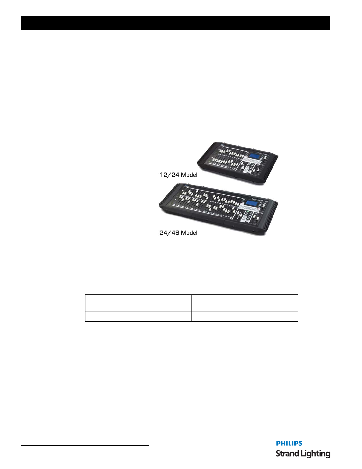
2. Product Descriptions
The 200 plus series consoles are the latest
in a long line of enhanced manual lighting
desks from Philips Strand Lighting. The
consoles feature Ethernet and DMX ports
as well as a video display port for users
needing more information than is
provided by the on panel LCD display.
Easy to set up and use the 200 plus series
consoles are ideal for any application that
needs manual and memory control. For
complete technical specifications, see
"TECHNICAL SPECIFICATIONS" on
page 72.
Figure 1: 200 Plus
Series Consoles
3. Compliance Information
This equipment is designed and manufactured to comply with international safety standards 1EC950, UL1950,
CS950 and is intended for use as part of a lighting cont rol system. It must not be used for other purposes where there
is a risk of safety to persons. The equipment contains power voltages, socket outlets shall be installed near to the
equipment and be easily accessible. All units are CE marked and include UL, cUL listed power supplies.
Working Voltage (Current) 100 - 120 V AC (2A) / 220 - 240 VAC (1A)
Frequency 50 / 60 Hz
Maximum Ambient Temperature
o
C (104oF) - Do not restrict ventilation
40
4. Included Items
Unpack the console from the packaging and check that the following components are contained within. If any parts
are missing, or damaged, please contact the carrier and your nearest Strand Lighting office.
• 200 Plus Series Console (either 12/24 or 24/48
model)
• 800 x 600 VGA monitor output card (installed
in console)
• Operation’s Manual (this document)
• Universal Power Supply (90 to 240 VAC, autoranging)
• Dust Cover
4 PREFACE
INTRODUCTION
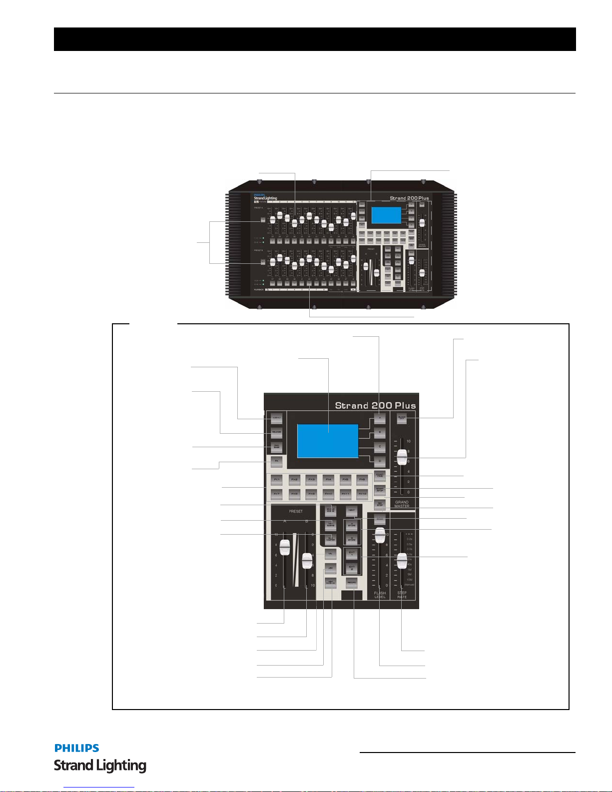
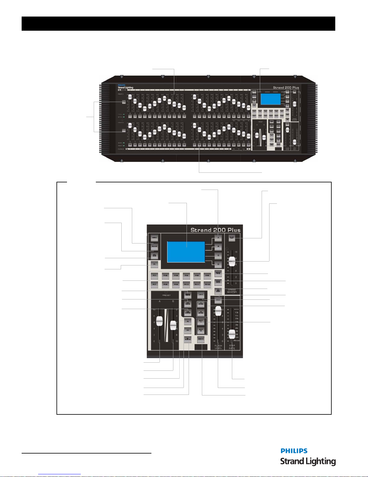
1. 200 Plus Series Console Layout
12/24 Version
Figure 2 illustrates the layout of the control features of the 200 Plus Series Console (12/24 version).
Channel Fader (1 - 24)
Channel
Expansion
Keys
200 Plus Series Console
See Detail A
Detail A
Menu Button
Release Button
DMXBase Button
FX Mode Button
FX Keys (1 - 12)
Single Scene
Two Scene
SubMaster
LCD Display Softkeys (A - D)
LCD Display
Fader Flash Button (1 - 24)
Blackout Button
Grand Master
FD/ST Time
Start/Stop
Go/Step
Solo
Next
A Store & B Store
EXT 1 & EXT 2
Preset A Master
Preset B Master
Note: For each control’s definition/purpose see "Glossary of Terms" on page 7
ML
LED Mode
PlayBack
Step Rate Fader
Flash Level Fader
Record
Figure 2: 200 Plus Series 12/24 Console Control Features
200 Plus Series Console Layout 5
Operations Manual
24/48 Version
Figure 3 illustrates the layout of the control features of the 200 Plus Series Console (24/48 version).
Channel
Expansion
Keys
Detail A
Menu Button
Release Button
Channel Fader (1 - 48)
LCD Display Softkeys (A - D)
LCD Display
See Detail A
Fader Flash Button (1 - 48)
Blackout Button
Grand Master
DMXBase Button
FX Mode Button
FX Keys (1 - 12)
Single Scene
Two Scene
SubMaster
Note: For each control’s definition/purpose see "Glossary of Terms" on page 7
Preset A Master
Preset B Master
ML
LED Mode
PlayBack
FD/ST Time
Go/Step
Next
A Store & B Store
EXT 1 & EXT 2
Step Rate Fader
Flash Level Fader
Record
Start/Stop
Solo
Figure 3: 200 Plus Series 24/48 Console Control Features
6 INTRODUCTION

200 Plus Series Console
2. Glossary of Terms
This section covers some of the common terms used throughout this manual.
Channel Expansion Keys: Key 1-48 & Key 49-96 (Key 12-24 & Key 25- 48)
Used to Page up/down for faders allowing the 24/48 console to control up to a maximum of 96 fader channels
(maximum of 48 faders on the 12/24). Pressing Key 1-48 will set the faders to control channels 1-48, Pressing Key
49-96 will set the faders to control channels 49-96.
Key 1, Key 2, Key 3, ...Key48
Under each channel fader is a flash button (bump button) for that channel.
SingleScene Button
Used to enter into Single Scene Mode which allows access to all the fader channels.
TwoScene
Used to enter into TwoScene Mode. Allows the console to be run in a standard two scene preset mode. This limits
access to 24 channels. (12 channels on the 12/24 version).
SubMaster
Used to enter into SubMaster Mode. Allows users to record generic channels into a memory for manual playback.
ML (Moving Light)
Used to enter into ML Mode. Allows for the programming of moving lights into Playback faders or into FX stacks.
LED Mode
Used to enter into LED Mode. Allows for the programming of LEDs into Playback faders or into FX stacks.
PlayBack
Used to enter into PlayBack Mode. Allows for access to submaster playback of generic lights and the manual
playback of ML and LED memories.
NEXT
Used to process CrossFade function in SingleScene Mode and submaster mode.
A Store / B Store
Used to store temporary memories when operating the console manually in Single Preset mode.
Record
Used to record submasters, playbacks and FX stacks.
EXT 1 and EXT 2
Allows remote control of DMX devices like smoke machines, toggles the remote device on or off.
Key A, Key B, Key C, Key D
Soft keys to allow access and navigation of the LCD screen.
Menu
Allows access into specific functions like patch, ML set up, LED set up etc.
FX 1 - 12
Selects the relevant FX key to allow programming or playback of FX stacks 1 through 12.
Release
Clear the current operations. This is useful for resetting MLs and LEDs when you have finished programming with
them.
DMX Base
This key allows the FX keys to play back memories stored and created using DMX in or from offline programming.
Glossary of Terms 7

Operations Manual
FD/ST TIME
The Fader Time is available when the indicator is red. The Step Time is available when the indicator is yellow.
Moving the Step Rate fader allows for a time to be set and stored in an FX stack. It is also possible to set ti mes
manually for all functions at any time.
Start/Stop
Used to activate or deactivate any of the FX1-12 stacks.
GO/STEP
Used to manually run through the steps in an activated FX stack.
SOLO
Sets the flash buttons under the faders to Solo mode, only that faders contents will flash to fu ll when th e flash butt on
is pushed.
Preset A and Preset B Faders
Used to manually fade between A bank of faders or B bank of faders in Two Preset mode. Used to fade between
stored A or B and preset faders in Single Preset mode.
Flash Level Fader
The maximum output level that will be output when a flash button is pushed.
Step Rate Fader
Allow for the setting of Fade Times or Step rates.
GrandMaster
The master fader controller of intensity output for the console, it is always active.
Note: CONVENTIONS - When a key is referred to in the manual it will be in capital letters. For instance RECORD
would refer to the record button. A softkey command on the LCD screen will be written contained inside "". So for
instance the "Enter" would refer to a softkey option available on the LCD screen. For operational information, refer to
"CONSOLE BASIC OPERATION" on page 12.
3. Getting Started
After unpacking the console and checking that you have all the included items shipped with your console (refer to
"Included Items" on page 4 for details), you may begin connecting your 200 Plus Series Console to power and
lighting system.
Site Requirements
The 200 Plus Series Console requires a sturdy, flat surface for installation (unless the unit is to be rack mounted - see
"Product Care" on page 11 for information). The surface should be able to support the weight of the console and
should provide suitable ventilation. Also, the site should be clean (i.e. absent of any construction dust or debris) and
dry. Before setting up, ensure that the installation site meets these requirements. For operational and space
requirements, refer to "TECHNICAL SPECIFICATIONS" on page 72.
8 INTRODUCTION

200 Plus Series Console
Console Rear Panel Connections and Controls
Figure 4 identifies all the connections and controls on the rear panel of the 200 Plus Control Console. Detailed
information is contained throughout the manual for each connection. Below is a list of connections and their purpose.
Power
Switch
Power Input
Ethernet Port (RJ45)
USB Port (Library Storage)
VGA Out (Monitor) DMX512 In
NOTES:
(1) DMX BASE is an advanced DMX512 port for the DMX BASE feature in the console. Please see
page 58
(2) The DMX512 connection is the primary DMX512 port.
for details.
DMX BASE
"Update DMX Base" on
Figure 4: 200 Plus Series Console Rear Panel Connections and Controls
Power Switch
Turns console On or Off. Note, turning off this switch does not disconnect power from console.
DMX512
(1)
(2)
Power Input
Power into console from universal (AC to DC) power supply. See “Connecting Power” on page 9 for details.
Ethernet Port (RJ45)
Art-Net connection for faster communication with the other compatible devices.
USB Port (Library Storage)
USB connection for connection of a USB drive to load libraries, save shows, or update console software.
VGA Out (Monitor)
VGA connection for driving a VGA video monitor. See “VGA connection for driving a VGA video monitor. for
details. Note, video monitor sold separately.” on page 9 for details. Note, video monitor sold separately.
DMX512 In
DMX512 input connection for DMX512 signals from another console or device. See “Connectin g DMX512” on
page 10 for details.
DMX512 Out (2 Connections)
DMX512 output connections for controlling DMX512 devices. The DMX BASE port allows output for DMX Based
functions. The DMX512 port allows output of D MX from the consoles functions. See “Connecting DMX512” on
page 10 for details.
Connecting Power
The power supply shipped with your 200 Plus Series Console is an auto-ranging, universal voltage supply. It operates
between 90 to 240 VAC.
To connect the power supply:
Step 1. As shown in Figure 5, make sure unit’s power switch is set to "Off"
Getting Started 9
Operations Manual
Step 2. Connect DC connector from power supply to DC IN on console.
Power Input
Connector Pinout
9 to 12 Volts DC
0.5 Amps (min.)
200 Plus Series Console Rear Panel
Console On / Off Switch
Power Input Connector
Figure 5: 200 Plus Series Control Console Power Connection
Step 3. Connect power supply to AC supply source.
Step 4. Turn on console at Console On / Off Switch.
Note: Y ou must connect the console to the lighting system via DMX512 before it is capable of providing control. See
"Connecting DMX512" on page 10 for more information.
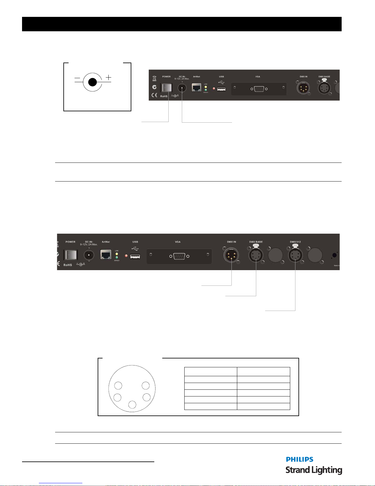
Connecting DMX512
The console provides two standard, female XLR 5-pin connector for connecting to DMX512 devices. DMX512 is for
outputting to a universe of DMX devices for your primary outpu t. This can include dimmers, LEDs, and moving
lights. The port labeled DMX BASE is for outputting to a universe of LED devices. For more information on DMX
BASE, refer to "DMX Base" on page 7.
200 Plus Series Console Rear Panel
DMX512 Input
DMX BASE
(1)
NOTES:
(1) DMX BASE is an advanced DMX512 port for the DMX BASE feature in the console. Please see
page 58
(2) The DMX512 connection is the primary DMX512 port.
for details.
DMX512
Connectors Pinout
5
4
Figure 6: 200 Plus Series Control Console DMX512 Connection
Note: For more information on DMX512, refer to "Additional Resources for DMX512" on page 1.
10 INTRODUCTION
DMX512
(2)
"Update DMX Base" on
Pin Signal
1 Ground
1
2
3
2Data 3Data +
4 No Connection
5 No Connection
200 Plus Series Console
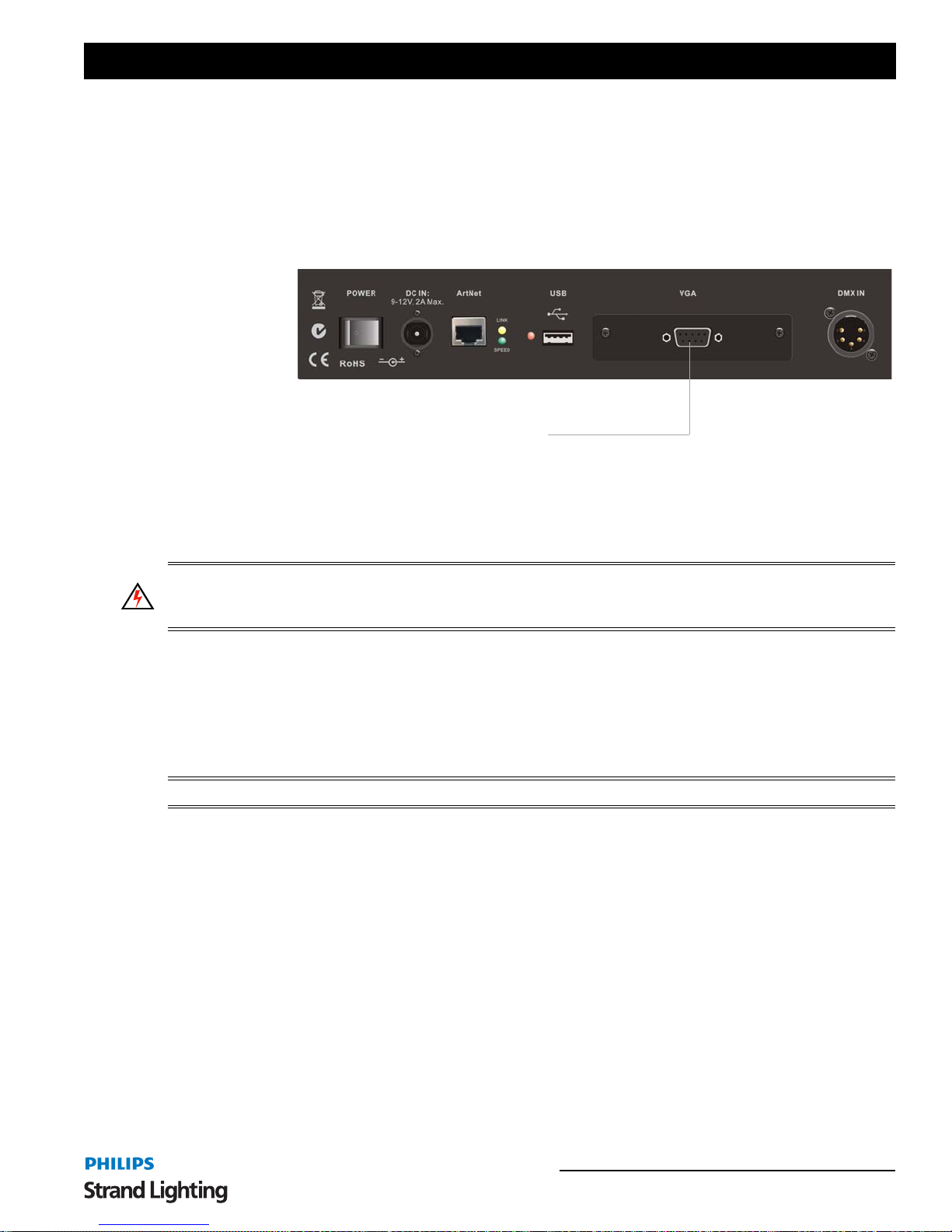
4. Video Monitor Connection
The 200 plus series console comes equipped with a VGA monitor output card and drives any standard VGA
monitor*.
200 Plus Series Console Rear Panel
VGA Monitor Output
(15-pin connector)
Figure 7: 200 Plus Series Control Console VGA Connection.
* Video monitor sold separately.
5. Product Care
WARNING! Do not use or place this device in vicinity of equipment that generates strong electromagnetic radiation
or magnetic fields. Strong static charges or strong magnetic fields produced by equipment such as radio transmitters
could interfere with the display or affect the product's internal circuitry.
The 200 Plus Series Console requires very little care and does not have any user-serviceable parts. Avoid spilling
liquid on the equipment If this should happen, switch the equip ment off immediat ely at the ma ins. To reduce the risk
of fire or electric shock, do not expose the equipment to rain or moisture.
In the event the console needs to be cleaned, remove all power from unit and use only a very mild soap on a damp
cloth. Never saturate the console with any cleaning solution. Dry immediately with a soft lint-free cloth after
cleaning.
WARNING! Never use harsh chemicals or solvents such as window cleaners, paint removers, etc.
When the console is not in use, turn off power using the console on / off switch and place included dust cover over
console.
6. Customer Service and Support
At Strand Lighting, we are committed to providing you the highest quality in customer service and produ ct support.
Whether your needs are telephone troubleshooting assistance or technical service, our full-time staff of experienced
professionals are on-hand to provide support. We also have a world-wide network of Authorized Strand Lighting
Service Centers. For a complete list of Authorized Strand Lighting Service Centers, please visit our web site at
www.strandlighting.com and click on the Support section.
For your nearest Strand Lighting office, please see "Strand Lighting Offices" on the inside front cover of this manual.
Video Monitor Connection 11

Operations Manual
CONSOLE BASIC OPERATION
Naming Conventions
When a key is referred to in the manual it will be in capital letters. For instance RECORD would refer to the record
button. A softkey command on the LCD screen will be written contained inside "". So for instance the "Enter" would
refer to a softkey option available on the LCD screen.
Note: All screen shots in the "CONSOLE BASIC OPERATION" section are simulated for clarity.
1. Two Scene Control
In Two Scene operation, separate scenes are set up on PRESET A and PRESET B faders. The A MASTER and B
MASTER faders are used to crossfade between the two different scenes.
Entering Two Scene Operation Mode
There are two ways of entering into Two Scene mode:
If the TWO SCENE button is not lit at all:
1) Press the TWO SCENE button once and it will turn yellow.
2) Press the TWO SCENE button a second time and it will turn dark green.
3) You are now in Two Scene mode.
Note: If any channels on PRESET A or PRESET B are above 0% and the relevant PRESET A or PRESET B
MASTER faders are at full the intensity of those channels will snap on.
Fading into TWO SCENE mode is also possible. If the TWO SCENE button is not lit at all:
1) Press the TWO SCENE button once and it will turn yellow.
2) If the PRESET A or PRESET B FADERS are at the bottom move them to the top. This will cross fade in
any channels set above 0% on the PRESET A faders and the TWO SCENE button will turn dark green or;
3) If the PRESET A or PRESET B FADERS are at the top move them to the bottom and then move them to
the top. This will cross fade in any channels set above 0% on the PRESET A faders and the TWO SCENE
button will go dark green.
In most cases during Two Scene operation you will want to control 24 channels (12 channels on the 12/24 version) as
this is the basic control mode. However it is possible to access up to 4 8 channels (24 on the 12/24 version) by using
the 1-48 (1-24) and the 49-96(25-49) buttons. You can page between the pages to set the levels as you require.
Remember to re-page to lower these channels if you have set them. The LCD next to the channel numbers you have
selected will light up to represent the channels that you are working with on each fader bank.
12 CONSOLE BASIC OPERATION
200 Plus Series Console
The monitor displays information (as shown in Figure 8) about Channel levels and the position of the A/B MASTER
faders.
REV1.00 Strand Lighting 2*48 GM: FL
01 02 03 04 05 06 07 08 09 10 11 12 13 14 15 16 17 18 19 20 21 22 23 24
25 26 27 28 29 30 31 32 33 34 35 36 37 38 39 40 41 42 43 44 45 46 47 48
49 50 51 52 53 54 55 56 57 58 59 60 61 62 63 64 65 66 67 68 69 70 71 72
73 74 75 76 77 78 79 80 81 82 83 84 85 86 87 88 89 90 91 92 93 94 95 96
Submaster Preset Effect
Page: 01
01 02 03 04 05 06 07 08 09 10 11 12
A B
FX Base
FX1 FX2 FX3
13 14 15 16 17 18 19 20 21 22 23 24
25 26 27 28 29 30 31 32 33 34 35 36
FL FL
37 38 39 40 41 42 43 44 45 46 47 48
FX4 FX5 FX6
FX7 FX8 FX9
FX10 FX11 FX12
Figure 8: Two Scene Operation - Video Monitor Screen
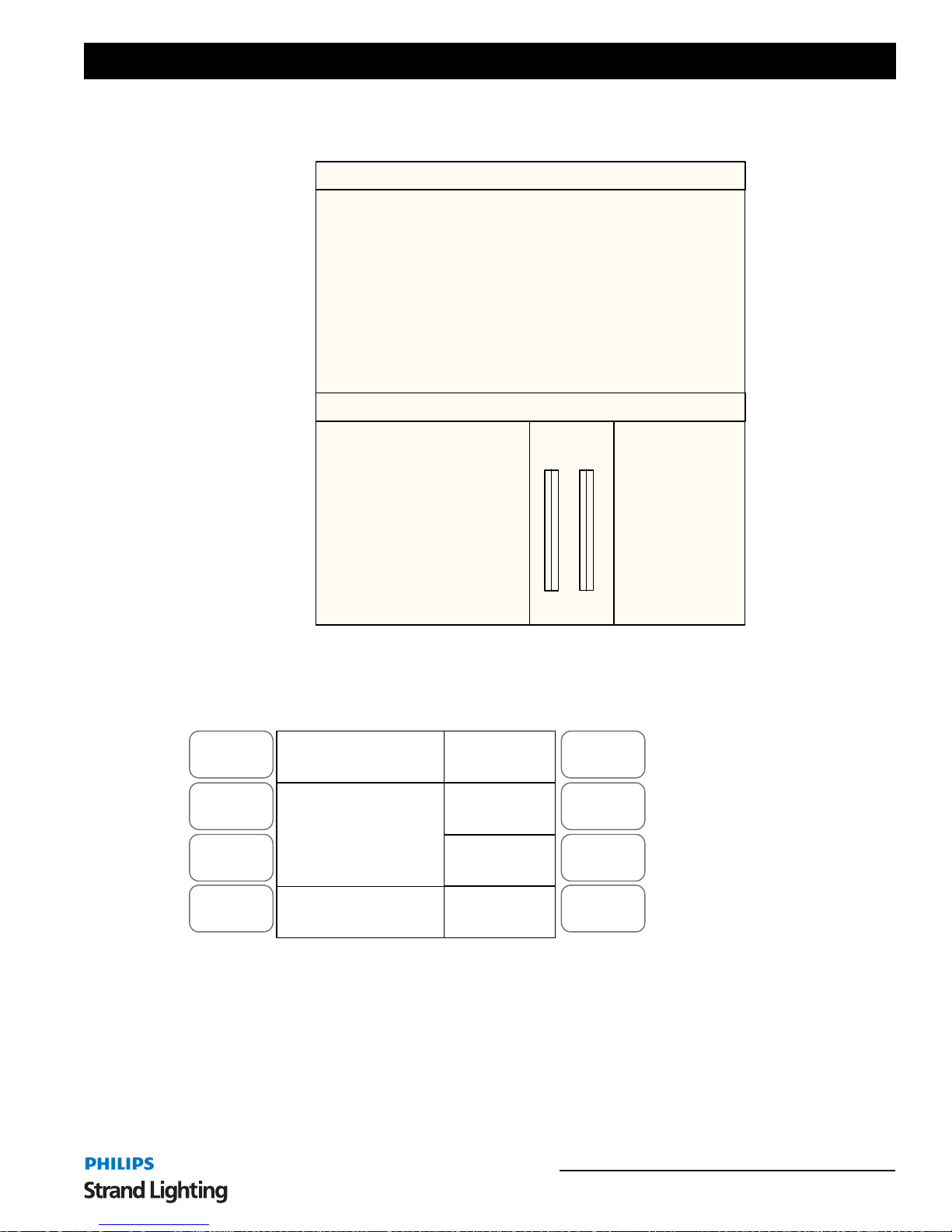
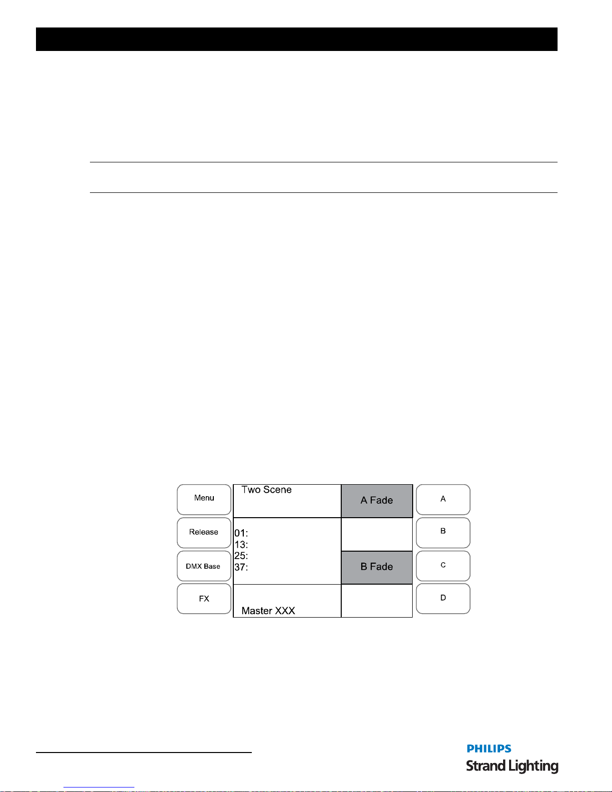
If a video monitor is disconnected or not used, the LCD can be used to show information during console operation.
Channel levels are shown as bar lines next to the numbers in the middle left window.
Menu
Release
DMX Base
FX
Two Scene
01:
13:
25:
37:
A Fade
B Fade
A
B
Note: The video monitor's
output will change color
schemes occasionally to
C
help minimize color burn
out on the monitor.
D
Master XXX
To Output a Scene from Preset A - Use the PRESET A faders to set the required levels for each channel. Set the
PRESET A MASTER to full and the PRESET B MASTER to zero (both faders will be at the top). The scene set up
on the PRESET A faders will output live.
To Output a Scene from Preset B faders- Set the required levels for each channel on the PRESET B faders. Set the
PRESET A MASTER to zero and the PRESET B MASTER to full (both faders will be at the bottom). The scene
set on the PRESET B faders will output live.
Figure 9: Two Scene Operation - LCD Display
Two Scene Control 13
Operations Manual
Example:
Note: As the PRESET MASTERS move to the bottom the intensity on channels 1,2 and 3 will fade to 0% and the
intensity on channels 10, 11 and 12 will fade to 100%.
Congratulations! You have just run your first lighting cue.
Timed Operation
Manual Fades
Use the PRESET A faders to set a scene. On the PRESET B faders set a different scene. Set the PRESET A
MASTER to full and the PRESET B MASTER to zero. This will output the channels set on the PRESET A faders.
To crossfade to the scene on PRESET B move the PRESET A MASTER to zero and the PRESET B MASTER to
full at the same time. The speed with which you m ove the master faders will control th e time taken for th e transition
between PRESET A and PRESET B. As the two master faders are moved the scene on the PRESET A faders will
fade out and the scene on the PRESET B faders will fade in.
A new scene can now be set up on the PRESET A faders without affecting the live outputs. To crossfade to the new
scene on PRESET A, move the PRESET A MASTER to full and the PRESET B MASTER to zero. As the two
master faders are moved the currently outputting scene set up on PRESET B faders will fade out and the scene set on
PRESET A faders will fade in.
Timed Fades
It is possible to set a fade time between scenes by using the STEP RATE fader. Make sure the FD/ST TIME button
is red by pressing the button as needed. When red, this indicates that the STEP RATE fader is in time mode. To apply
the time press the A and C soft buttons on the right of the LCD, the text will invert its colors to show the selection has
occurred. This will apply the time on the STEP RATE FADER to the PRESET A and PRESET B faders. Set the
time to the desired level. When you move the PRESET A and PRESET B faders the time will now be applied to the
transition. The LCD will show the time in the bottom Left window.
1) Make sure that the PRESET A MASTER and PRESET B MASTER faders are at the top.
2) Set PRESET A faders 1, 2 and 3 to 100%. (as you move these faders to 100% you will see the intensities of
these channels turn on)
3) Set PRESET B faders 10, 11, 12 to 100%. You will see no change in these channels intensities in real time .
4) Move the PRESET A MASTER and PRESET B MASTER fader to the bottom.
The example below will show you how to set and apply Time to the Preset Master moves.
Example:
1) Make sure that the PRESET A MASTER and PRESET B MASTER faders are at the top.
2) Set PRESET A faders 1, 2 and 3 to 100%. (as you move these faders to 100% you will see the intensities of
these channels come on)
14 CONSOLE BASIC OPERATION
Figure 10: Timed Fades - LCD Display
200 Plus Series Console
3) Set PRESET B faders 10, 11, 12 to 100%.
4) Ensure that the PRESET A and PRESET B faders have been selected in the LCD window.
5) Use the STEP RATE fader to set the desired time, 5 secs.
6) Move the PRESET A MASTER and PRESET B MASTER FADERS to the bottom quickly.
Note: The time will be used to control the crossfade.
Flashing Channels
Pressing the flash button (Bump Button) of any channel fader will flash that channel to the level set by the FLASH
MASTER. This will be added to the scene. If the SOLO button is selected then any channels flashed will come on
and all other channels will go to 0%.
2. Single Scene Operation
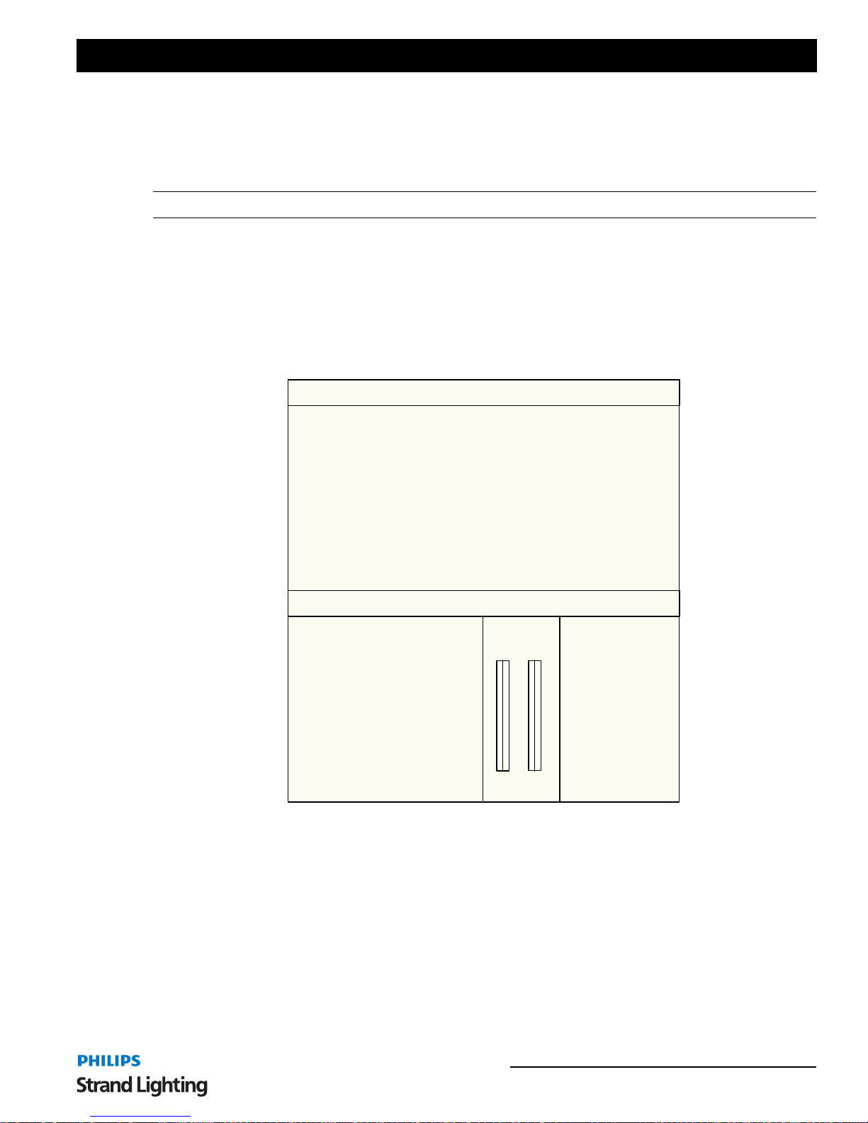
The monitor display is similar to that for Two Scene.
REV1.00 Strand Lighting 1*96 GM: FL
01 02 03 04 05 06 07 08 09 10 11 12 13 14 15 16 17 18 19 20 21 22 23 24
25 26 27 28 29 30 31 32 33 34 35 36 37 38 39 40 41 42 43 44 45 46 47 48
49 50 51 52 53 54 55 56 57 58 59 60 61 62 63 64 65 66 67 68 69 70 71 72
73 74 75 76 77 78 79 80 81 82 83 84 85 86 87 88 89 90 91 92 93 94 95 96
Submaster Preset Effect
Page: 01
01 02 03 04 05 06 07 08 09 10 11 12
13 14 15 16 17 18 19 20 21 22 23 24
25 26 27 28 29 30 31 32 33 34 35 36
37 38 39 40 41 42 43 44 45 46 47 48
A B
FL FL
FX Base
FX1 FX2 FX3
FX4 FX5 FX6
FX7 FX8 FX9
FX10 FX11 FX12
Figure 11: Single Scene Operation - Video Monitor Display
Single Scene Operation 15
Operations Manual
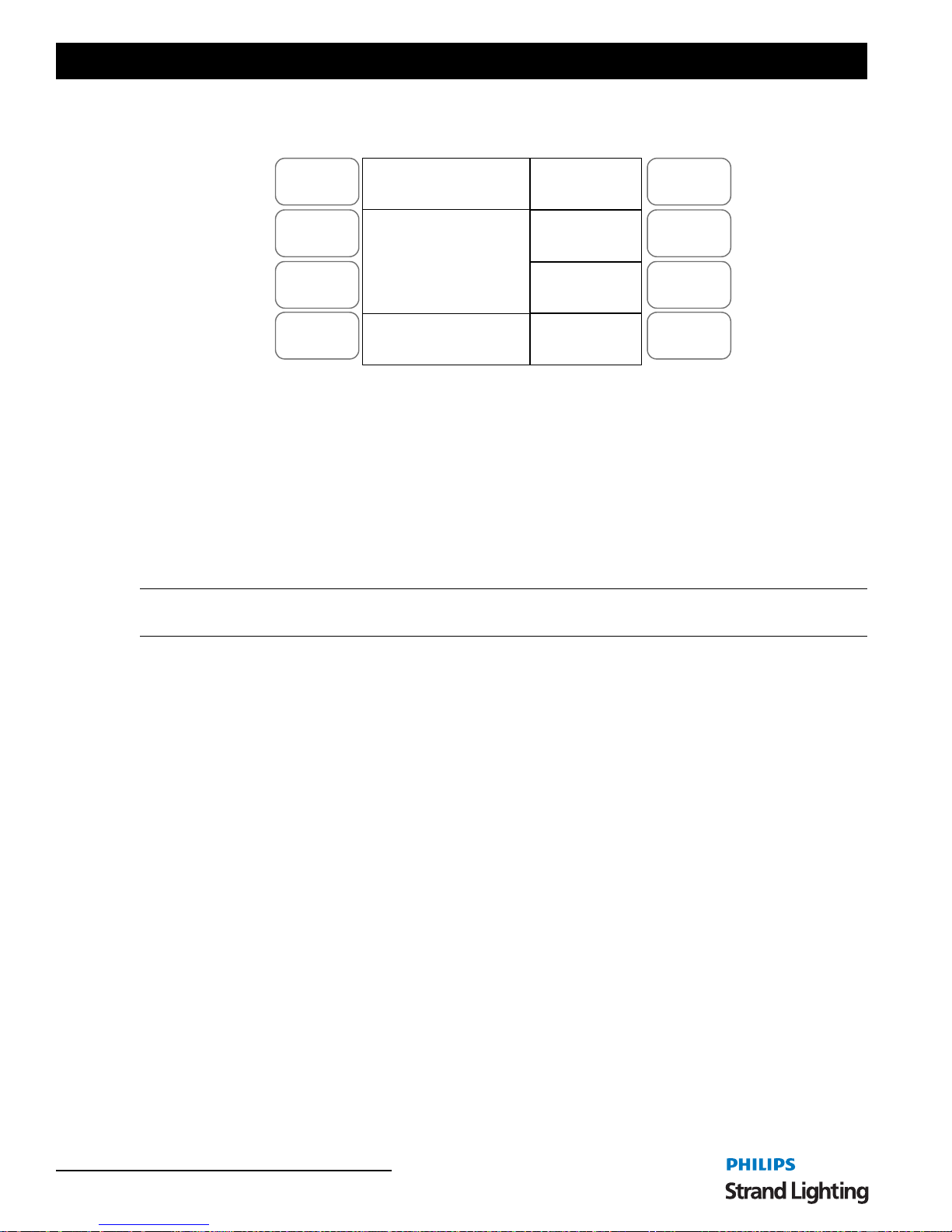
If the video (VGA) display card is disconnected or a video monitor is not used, you can still view informatio n on the
LCD screen.
Menu
Release
Single Scene
01:
A Fade
A
B
13:
DMX Base
FX
25:
37:
B Fade
C
D
Master XXX
Figure 12: Single Scene Operation - LCD Display
Entering Single Scene Operation Mode
There are two ways of entering Single Scene mode:
If the SINGLE SCENE button is not lit at all:
1) Press the SINGLE SCENE button once and it will turn yellow.
2) Press the SINGLE SCENE button a second time and it will turn dark green.
3) You are now in Single Scene mode.
Note: Be aware that if any channels on PRESET A or PRESET B are above 0% and the relevant PRESET A or
PRESET B MASTER faders are at full the intensity of those channels will snap on.
Fading into Single Scene mode is also possible. If the SINGLE SCENE button is not lit at all:
1) Press the SINGLE SCENE button once and it will turn yellow.
2) If the PRESET A or PRESET B FADERS are at the bottom move them to the top. This will cross fade in
any channels set above 0% on the PRESET A faders and the SINGLE SCENE button will turn dark green.
Or
3) If the PRESET A or PRESET B FADERS are at the top move them to the bottom and then move them to
the top. This will cross fade in any channels set above 0% on the PRESET A faders and the SINGLE
SCENE button will turn dark green.
In most cases during Single Scene operation you will only want to control 4 8 channels (24 channels on the 12/24
version) as this is the basic control mode. However it is possible to access up to 96 channels (48 on the 12/24 version)
by using the 1-48 (1-24) and the 49-96 (25-49) buttons. You can page between the pages to set the levels as you
require. Remember to re-page to lower these channels if you have set them. The LCD next to the channel numbers
you have selected will light to show which ones you are working on.
Setting a Scene
In Single Scene Mode you are able to crossfade between, or combine two scenes which are 48 channels wide (24
channels on the 12/24 version). To use this function, the NEXT button must be activated. This will allow the A
STORE and B STORE buttons to be used. Select the NEXT button and it will turn red.
A scene is set up using both the PRESET A and PRESET B faders (PRESET A faders control channels 1-24,
PRESET B faders control channels 24 - 48). This scene can then be stored temporarily by pressing the A STORE if
the PRESET A fader is at full or in the B STORE button if the PRESET B fader is at full.
A second scene can then be set up on the PRESET A and PRESET B faders. The A PRESET and B PRESET
MASTER faders can then be used to crossfade between the two scenes.
16 CONSOLE BASIC OPERATION

200 Plus Series Console
Example:
1) Press the NEXT button to select the crossfade mode for single scene operation.
2) Make sure that the PRESET A MASTER and PRESET B MASTER faders are at the top.
3) Set the faders 1, 2, 3, 22, 23 and 24 to 100%. (as you move these faders to 100% you will see the intensities
of these channels come on)
4) Press the A STORE button. It will turn red.
5) Reset the faders so 10, 11, 12, 19, 20 and 21 are at 100%. You will see no change in these channels
intensities in real time.
6) Move the PRESET A MASTER and PRESET B MASTER FADERS to the bottom.
7) The A STORE button will flash.
8) Press the B STORE button it will turn red. The A STORE button will stop flashing.
9) Reset the faders so 5, 6, 7, 13, 14 and 15 are at 100%.
10)Move the PRESET A MASTER and PRESET B MASTER FADERS to the top.
11)The B STORE button will flash.
Congratulations! You have run three cues in Single Scene Mode.
When cross fade occurs the A STORE button will continue to flash until a scene is stored in the B STORE button.
This means a scene can be reused.
Example:
1) Press the NEXT button to select the crossfade mode for single scene operation.
2) Make sure that the PRESET A MASTER and PRESET B MASTER FADERS are at the top.
3) Set the faders 1, 2, 3, 22, 23 and 24 to 100%. (as you move these faders to 100% you will see the intensities
of these channels come on)
4) Press the A STORE button. It will turn red.
5) Reset the faders so 10, 11, 12, 19, 20 and 21 are at 100%. You will see no change in these channels
intensities in real time.
6) Move the PRESET A MASTER and PRESET B MASTER FADERS to the bottom. Channels 10, 11, 12,
19, 20 and 21 will be outputting at 100%.
7) The A STORE button will flash.
8) Move the PRESET A MASTER and PRESET B MASTER FADERS to the top.
9) Channels 1,2,3,22,23 and 24 will be ou tput ting at 100%. The A STORE button will continue to flash.
10)Reset channels 7,8,9,14,15 and 16 to 100%.
11) Move the PRESET A MASTER and PRESET B MASTER FADERS to the bottom. Channels will be
7,8,9,14,15 and 16 outputting at 100%.
12)The A STORE button will flash.
13)Press the B STORE button. It will turn red. The A STORE button will stop flashing
14)Reset channels 10, 11, 12, 20, 21 and 22 to 100%.
15)Move the PRESET A MASTER and PRESET B MASTER FADERS to the top. Channels 11, 12, 20, 21
and 22 to 100% will be outputting. The
B STORE button will flash.
Timed Fades
It is possible to set a fade time between scenes by using the STEP RATE fader. Make sure the FD/ST TIME button
is red by pressing the button as needed. When red, this indicates that the STEP RATE fader is in time mode. To apply
the time press the A and C soft buttons on the right of the LCD, the text will invert its colors to show the selection has
occurred. This will apply the time on the STEP RATE FADER to the PRESET A and PRESET B faders. Set the
time to the desired level. When you move the PRESET A and PRESET B faders the time will now be applied to the
transition. The LCD will show the time in the bottom Left window.
Single Scene Operation 17

Operations Manual
To leave the crossfade function in Single Preset mode press the NEXT button when the PRESET A and PRESET B
MASTER faders are at the top. This will turn out the red light and the A STORE and B STORE buttons will be
inactive.
3. Submaster Operation
In Submaster mode it is possible to store generic channels and play them back using the PRESET A and PRESET B
faders as submasters.
Recording a Submaster
Set the console to Single Scene or Two Scene mode. Remember, Single Scene gives you access to more channels.
Set the level of the channels using the PRESET A and PRESET B faders. Once you hav e set the levels to the
intensity required press the RECORD button. The flash buttons under the faders will begin to flash red. Select which
of the available 48 submasters (24 on the 12/24 version) you wish to store the set channels in and press the flash
button associated with that submaster. The flash buttons will stop flashing and the button of the submaster you have
recorded to will go red. You can see the record function happening in the lower left corner of the LCD screen, a series
of blocks will scroll across the screen as the memory is written.
Example:
1) Go into Single Scene Mode.
2) Set channels 1, 2, 3 and 4 to 100%. Set channels 9, 10, 11 and 12 to 50%.
3) Press RECORD.
4) Select Submaster 1 by pressing the flash butto n under Fader 1.
5) Set channels 5 through 10 to 75% and channels 15 throu gh 24 to 30%.
6) Press RECORD.
7) Select Submaster 5 by pressing the flash butto n under Fader 5.
8) Set channels 12 through 18 to 100% and channels 1 through 9 at 40%.
9) Press RECORD.
10)Select the Submaster 9 by pressing the flash button under Fade r 9.
Congratulations! You have recorded three Submasters.
Playing Back a Submaster
Set all the channel faders to 0%. Press the SUBMASTER button. It will turn red.
The flash button below any submaster in which information has been stored will be red. You can output the submaster
by raising that fader to 100%. If you press the flash button you will flash the contents of the submaster to the level set
by the FLASH LEVEL fader.
Example: (we will use the three submasters recorded in "Recording a Submaster")
1) Go to Submaster mode by pressing the SUBMASTER button. It will turn red to show that Submaster mode
is selected.
2) The flash buttons under Faders 1, 5 and 9 will be red.
3) Raise Fader 1 to 100%. Channels 1 through 4 and 9 thro ugh 12 will be outputting at their recorded values.
4) Lower Fader 1 and raise Fader 5, channels 5 through 10 and 15 through 24 will be playing back at their
recorded levels.
5) Lower Fader 5 and raise Fader 9, channels 12 through 18 and channels 1 through 9 will be outputting at
their recorded values.
Playing Back a Submaster with Time
It is possible to assign a time to a Submaster fader. This time will be used to fade the submaster in and out. There are
two ways to assign a time to a Submaster, when recording it or after it is recorded.
18 CONSOLE BASIC OPERATION
200 Plus Series Console
T o set the time for a Submaster when recording it set the channels levels as described in recording submasters section.
Press the RECORD button, set the time using the STEP RATE fader. The time will be shown in the lower left
window of the LCD screen. Select which Submaster you wish to record to by pressing the relevant flash button.
Example:
1) Set channel faders 1 through 12 to 100%.
2) Press RECORD.
3) Adjust the time to 5 seconds using the STEP RATE fader.
4) Select Submaster 8 by pressing the relevant flash button.
5) Enter Submaster mode by pressing the SUBMASTER button.
6) Raise Submaster fader 8. Channels 1 through 12 will fade to 100% over 5 seconds.
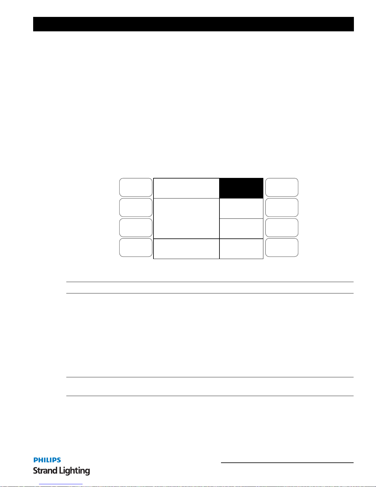
It is also possible to assign a time or edit a time within an existing Submaster. To do this you need to be in Submaster
mode. Press the SOFT KEY A next to the LCD screen to select the ASSIGN FADE function. ASSIGN FADE will
invert its colors to show it is selected. Adjust the STEP RATE fader to the required time, the time will be shown in
the lower left window of the LCD, while holding down the flash button of the Submaster you wish to assign t he ti me
to.
Menu
Release
DMX Base
FX
Submaster Mode
01:
13:
25:
37:
Assign Fade
Fade
A
Fade
B
A
B
C
D
Master xxx
Figure 13: Assign Fade Function - LCD Display
Note: To leave the ASSIGN FADE function, press the SOFT KEY A.
Example:
We will edit the time set in one of the Submasters we recorded earlier.
1) Go into Submaster mo de by pressi ng the SUBMASTER BUTTON.
2) Select the ASSIGN FADE function by pressing the SOFT KEY A.
3) Adjust the time using the STEP RATE fader to 10 seconds while holding down the flash key under
Submaster 1.
4) Playback Submaster 1. The channels will fade in over 10 seconds.
5) Lower Submaster 1 to 0%. The channels will fade to 0% over 10 seconds.
Note: It is possible to override a stored time while it is playing back. While holding the Submasters Flash Button,
move the STEP RATE Fader. You can speed up or slow down the time.
Changing Submaster Pages
There are 24 pages of 48 Submasters (12 Pages of 24 Submasters on the 12/24 version) available.
Submaster Operation 19
Operations Manual
To change pages, hold down the SUBMASTER button. The LCD screen will show the following:
Menu
Release
DMX Base
FX
Submaster Mode
01:
13:
25:
37:
Assign Fade
Fade
A
Fade
B
A
B
C
D
P:01 Select 1 - 24
Figure 14: Submaster Mode - LCD Display
The display in the lower left window shows that the console is on Page 1 (P:01) and that there are 24 pages available.
To select a different page the Flash buttons 1 to 24 are used (1 to 12 on the 12/24 version). To select Submaster Page
4 you would select the Flash button 4 while holding down the
While the
SUBMASTER button is held down the light in th e currently select Su bmaster p age will be lit. Subm aster
SUBMASTER button.
pages that have Submasters recorded on them will flash.
If a Submaster is currently outputting and the page is changed it will contin ue to output and the flash button for t hat
Submaster will flash. Once the Submaster has been lowered to 0% it will change pages and be available for use on the
newly selected page.
Playing Back Submasters Sequentially
It is possible to play back the recorded Submasters on a page sequentially using the PRESET A and PRESET B
MASTER
start with the first recorded memory and end with the last recorded memory on that page before cycling back to the
first memory.
faders. This allows you to playback recorded Submasters as a theatrical style cue stack. The sequence will
Note: Any Submasters that have no values stored in them will be ignored in the sequence.
To access this function ensure that the
MASTER
at 0 and PRESET B FADER at 10).Press the NEXT button, it will turn blue to show you have selected
PRESET A and PRESET B MASTER faders are at the bottom (PRESET A
Sequential Submaster Playback.
The Flash button of the first recorded fader will flash yellow. Raise the
PRESET A and PRESET B faders to the
top. The first recorded Submaster will output. Its flash button will turn solid yellow. The next sequential Submaster's
flash button will flash yellow. Lower the
PRESET A and PRESET B FADERS to the bottom. This will select the
next memory.
There are three ways to exit the sequential playback:
1) Move
PRESET A MASTER to 0% if it is at Full (top) or move PRESET B MASTER to 0% if it is at Full
(bottom). This will fade the last Submaster that was outputting to 0%. The
NEXT button’s blue light will go
out.
2) Press the
NEXT button. This will snap the last outputting Submaster to 0%. The NEXT button’s blue light
will go out.
3) You can fade into Single Scene or Two Scene Mode. Select Single Scene for instance, it will turn yellow.
Set the channel faders to the values that you require. If the
PRESET A and PRESET B MASTERS are at
the bottom, move them to the top. If they are at the top you will need to move them to the bottom and then
back to the top. This will fade in the values that you have set on the channel faders.
Example:
1) Record a variety of channel levels into Submasters 1, 5, 9, 15, 20, 21 and 22.
20 CONSOLE BASIC OPERATION
200 Plus Series Console
2) Move PRESET A and PRESET B MASTERS to th e bottom.
3) Press the
4) Raise the
NEXT key. It will turn blue. The flash button under Submaster 1 will flash yellow.
PRESET A and PRESET B MASTER faders. This will output Submaster 1 and its flash button
will turn yellow. Submaster 5's flash button will now be flashing yellow.
5) Lower
PRESET A and PRESET B MASTER faders to the bottom. This will output Submaster 5.
6) Continue the sequence until you have run through all of the stored submasters.
7) To exit the Sequence move
PRESET A MASTER fader to the bottom. The blue light in the NEXT button
will go out.
Note: It is possible to change Submaster pages during the sequential playback and the memories on the newly
selected page will then fade in and run in sequence the next time the
PRESET A and PRESET B MASTER faders
are moved.
Using Time to Playback Submasters Sequentially
It is also possible to use times when playing back the Submasters sequentially. Make sure the FD/ST TIME button is
red by pressing the button as needed. When red, this indicates that the
the time press
the selection has occurred. This will apply the time on the
SOFTKEY B and SOFTKEY C buttons on the right of the LCD, the text will invert its colors to show
STEP RATE FADER to the PRESET A and PRESET B
faders. Set the time to the desired level. When you move the PRESET A and PRESET B faders the time will now
be applied to the transition.
STEP RATE fader is in time mode. To apply
REV1.00 Strand Lighting Submaster GM: FL
01 02 03 04 05 06 07 08 09 10 11 12 13 14 15 16 17 18 19 20 21 22 23 24
50 50 50 33 33 FL FL FL
25 26 27 28 29 30 31 32 33 34 35 36 37 38 39 40 41 42 43 44 45 46 47 48
49 50 51 52 53 54 55 56 57 58 59 60 61 62 63 64 65 66 67 68 69 70 71 72
73 74 75 76 77 78 79 80 81 82 83 84 85 86 87 88 89 90 91 92 93 94 95 96
Submaster Preset Effect
Page: 01
01 02 03 04 05 06 07 08 09 10 11 12
13 14 15 16 17 18 19 20 21 22 23 24
25 26 27 28 29 30 31 32 33 34 35 36
37 38 39 40 41 42 43 44 45 46 47 48
A B
CrossFade
In 02 Out 01
FL FL
1.49 1.49
FX Base
FX1 FX2 FX3
FX4 FX5 FX6
FX7 FX8 FX9
FX10 FX11 FX12
Figure 15: Using Time to Playback Submasters Sequentially - Video Monitor Display
Monitor showing a crossfade from Submaster 01 to 02 running. The time is set to 1.49 seconds and the lines in the
Preset display move to show the fade happening. The channel levels are shown changing in real time.
Submaster Operation 21
 Loading...