

Philips 44PL9523, 55PL9223, 55PL9523 User Manual

3135 035 21303
44PL9523
55PL9523
55PL9223
Refer to the Quick Use and Setup Guide (supplied with your TV)
for information on basic connections, remote control button
descriptions, on-screen menu language, and Autoprogram.
Highlights
• Liquid-crystal-on-silicon (LCOS) High-definition
Imaging
• High-resolution Display—1280 x 720 pixels
Features
• Digital Natural Motion™
• Active Control™—analyzes and adjusts incoming signal
• Two-tuner, Double-window PIP (Picture-in-Picture)
• Dolby
®
Virtual Surround, 40-watt RMS
• 3D Y/C Comb Filter
• HD Component and DVI Input
• Center Channel Audio Input
• Side AV Convenience Jacks
• Matching stand and swivel available
04/06/04
HDTV Monitor
HDTV Monitor

2
Registering your model with PHILIPS makes you eligible for all of the valuable benefits listed below, so don't miss out.
Complete and return your Product Registration Card at once to ensure:
Return your Product Registration Card today
to get the very most from your purchase.
Visit our World Wide Web Site at http://www.philips.com
Congratulations on your purchase,
and welcome to the “family!”
Dear PHILIPS product owner:
Thank you for your confidence in PHILIPS.You’ve selected one of
the best-built, best-backed products available today.We’ll do everything in our power to keep you happy with your purchase for many
years to come.
As a member of the PHILIPS “family,” you’re entitled to protection
by one of the most comprehensive warranties and outstanding
service networks in the industry.What’s more, your purchase guarantees you’ll receive all the information and special offers for which
you qualify, plus easy access to accessories from our convenient
home shopping network.
Most importantly, you can count on our uncompromising commitment to your total satisfaction.
All of this is our way of saying welcome - and thanks for investing
in a PHILIPS product.
P.S. To get the most from your PHILIPS purchase, be
sure to complete and return your Product Registration
Card at once.
For Customer Use
Enter below the Serial No. which is located on the rear of the cabinet. Retain this
information for future reference.
Model No.__________________________
Serial No. ________________________
Know these
safetysymbols
This “bolt of lightning” indicates unin-
sulated material within your unit may
cause an electrical shock. For the safety of
everyone in your household, please do not
remove product covering.
The “exclamation point” calls atten-
tion to features for which you should
read the enclosed literature closely to prevent operating and maintenance problems.
WARNING: To reduce the risk of fire or
electric shock, this apparatus should not be
exposed to rain or moisture and objects
filled with liquids, such as vases, should not
be placed on this apparatus.
CAUTION: To prevent electric shock,
match wide blade of plug to wide slot, fully
insert.
ATTENTION: Pour éviter les choc électriques, introduire la lame la plus large de la
fiche dans la borne correspondante de la
prise et pousser jusqu’au fond.
t
s
*Proof of
Purchase
Returning the enclosed card guarantees
that your date of purchase will be on file,
so no additional paperwork will be
required from you to obtain warranty
service.
*Product Safety
Notification
By registering your product, you'll receive
notification - directly from the manufacturer - in the rare case of a product
recall or safety defect.
*Additional Benefits
of Product Ownership
Registering your product guarantees that
you'll receive all of the privileges to
which you're entitled, including special
money-saving offers.

3
IMPORTANT SAFETY INSTRUCTIONS
Read before operating equipment
1. Read these instructions.
2. Keep these instructions.
3. Heed all warnings.
4. Follow all instructions.
5. Do not use this apparatus near water.
6. Clean only with a dry cloth.
7. Do not block any of the ventilation openings. Install in accordance
with the manufacturers instructions.
8. Do not install near any heat sources such as radiators, heat regis-
ters, stoves, or other apparatus (including amplifiers) that produce
heat.
9. Do not defeat the safety purpose of the polarized or grounding-
type plug. A polarized plug has two blades with one wider than
the other. A grounding type plug has two blades and third grounding prong. The wide blade or third prong are provided for your
safety. If the provided plug does not fit into your outlet, consult an
electrician for replacement of the obsolete outlet.
10. Protect the power cord from being walked on or pinched particu-
larly at plugs, convenience receptacles, and the point where they
exit from the apparatus.
11. Only use attachments/accessories specified by the manufacturer.
12. Use only with a cart, stand, tripod, bracket, or table
specified by the manufacturer, or sold with the app-
aratus. When a cart is used, use caution when moving
the cart/apparatus combination to avoid injury from tip-over.
13. Unplug this apparatus during lightning storms or when unused for
long periods of time.
14. Refer all servicing to qualified service personnel. Servicing is
required when the apparatus has been damaged in any way, such
as power-supply cord or plug is damaged, liquid has been spilled
or objects have fallen into apparatus, the apparatus has been
exposed to rain or moisture, does not operate normally, or has
been dropped.
15. This product may contain lead and mercury. Disposal of these
materials may be regulated due to environmental considerations.
For disposal or recycling information, please contact your local
authorities or the Electronic Industries Alliance: www.eiae.org
16. Damage Requiring Service - The appliance should be serviced
by qualified service personnel when:
A. The power supply cord or the plug has been damaged; or
B. Objects have fallen, or liquid has been spilled into the appli-
ance; or
C. The appliance has been exposed to rain; or
D. The appliance does not appear to operate normally or
exhibits a marked change in performance; or
E. The appliance has been dropped, or the enclosure damaged.
17. Tilt/Stability - All televisions must comply with recommended
international global safety standards for tilt and stability properties
of its cabinet design.
• Do not compromise these design standards by applying excessive pull force to the front, or top, of the cabinet which could ultimately overturn the product.
• Also, do not endanger yourself, or children, by placing electronic equipment/toys on the top of the cabinet. Such items could
unsuspectingly fall from the top of the set and cause product damage and/or personal injury.
18. Wall or Ceiling Mounting - The appliance should be mounted to
a wall or ceiling only as recommended by the manufacturer.
19. Power Lines - An outdoor antenna should be located away from
power lines.
20. Outdoor Antenna Grounding - If an outside antenna is connected to
the receiver, be sure the antenna system is grounded so as to provide
some protection against voltage surges and built up static charges.
Section 810 of the National Electric Code, ANSI/NFPA No. 701984, provides information with respect to proper grounding of
the mast and supporting structure, grounding of the lead-in wire to
an antenna discharge unit, size of grounding connectors, location
of antenna-discharge unit, connection to grounding electrodes, and
requirements for the grounding electrode. See Figure below.
21. Object and Liquid Entry - Care should be taken so that objects
do not fall and liquids are not spilled into the enclosure through
openings.
a) Warning: To reduce the risk of fire or electric shock, this apparatus should not be exposed to rain or moisture and objects filled
with liquids, such as vases, should not be placed on this apparatus.
22. Battery Usage CAUTION - To prevent battery leakage that may
result in bodily injury, property damage, or damage to the unit:
• Install all batteries correctly, with + and - aligned as marked on
the unit.
• Do not mix batteries (old and new or carbon and alkaline, etc.).
• Remove batteries when the unit is not used for a long time.
Example of Antenna Grounding
as per NEC - National Electric Code
Note to the CATV system installer: This reminder is provided to call the CATV system installer's attention to Article 820-40 of the NEC
that provides guidelines for proper grounding and, in particular, specifies that the cable ground shall be connected to the grounding system of the
building, as close to the point of cable entry as practical.
GROUND CLAMP
ELECTRIC SERVICE EQUIPMENT
POWER SERVICE GROUNDING ELECTRODE SYSTEM (NEC ART 250, PART H)
ANTENNA LEAD IN WIRE
ANTENNA DISCHARGE UNIT
GROUNDING CONDUCTORS (NEC SECTION 810-21)
GROUND CLAMPS
(NEC SECTION 810-20)

4
Contents
INTRODUCTION
Welcome/Registration of Your TV . . . . . . . . . . . . . . . . .2
Safety/Precautions . . . . . . . . . . . . . . . . . . . . . . . . . . . . . .2–3
Features . . . . . . . . . . . . . . . . . . . . . . . . . . . . . . . . . . . . . . . .5
CONNECTING ACCESSORY DEVICES
TO
YOUR TV
Information about TV Signals . . . . . . . . . . . . . . . . . . . . . . . .6
Descriptions of Jacks, Cables, and Connectors . . . . . . . . . . .7
Panel Jack Compatibility Information . . . . . . . . . . . . . . . . . .8
Pre-connection Recommendations . . . . . . . . . . . . . . . . . . .9
Connecting a VCR . . . . . . . . . . . . . . . . . . . . . . . . . . . . . . .10
Connecting a VCR and Cable Box . . . . . . . . . . . . . . . . . . .11
Connecting an S-Video Device . . . . . . . . . . . . . . . . . . . . .12
Connecting a Standard DVD Player . . . . . . . . . . . . . . . . . .13
Connecting a Progressive-scan DVD Player . . . . . . . . . . . .14
Connecting an HD Satellite Receiver to YPbPr . . . . . . . . .15
Connecting an HD Satellite Receiver to DVI . . . . . . . . . . .16
Connecting Surround Sound Equipment . . . . . . . . . . . . . .17
Connecting to the Side Inputs:Video Game System . . . . . .18
Labeling the Audio/Video Input Sources . . . . . . . . . . . . . . .19
USING THE REMOTE CONTROL
Remote Control Buttons . . . . . . . . . . . . . . . . . . . . . . .20–21
Programming the Remote Control . . . . . . . . . . . . . . . .22–23
Setup Codes for Accessory Devices . . . . . . . . . . . . . . .24–25
Using the TV Remote’s VCR-specific Buttons . . . . . . . . . . .26
Using Active Control™ Plus . . . . . . . . . . . . . . . . . . . . . . .27
Using the Zoom Control . . . . . . . . . . . . . . . . . . . . . . . . . .28
U
SING THE ON-SCREEN MENUS
PICTURE
Adjusting/Setting the Picture Controls . . . . . . . . . . . . . . . .29
Selecting a Digital Processing Option . . . . . . . . . . . . . . . . .30
Selecting a Dynamic Contrast Option . . . . . . . . . . . . . . . .31
Selecting a DNR (Dynamic Noise Reduction) Option . . . .32
Turning on Color Enhancement . . . . . . . . . . . . . . . . . . . . .33
Selecting an AutoPicture™ Option . . . . . . . . . . . . . . . . . .34
Selecting a Picture Format Option . . . . . . . . . . . . . . . .35–36
SOUND
Adjusting the TV and Headphone Volume . . . . . . . . . . . . .37
Selecting a TV Equalizer Option . . . . . . . . . . . . . . . . . . . . .38
Adjusting TV Speaker Balance . . . . . . . . . . . . . . . . . . . . . .39
Turning Loudness on or off . . . . . . . . . . . . . . . . . . . . . . . .40
Selecting a Sound Mode Option . . . . . . . . . . . . . . . . . . . .41
Using Alternate Audio (SAP) . . . . . . . . . . . . . . . . . . . . . . .42
Setting the TV for Stereo Programming . . . . . . . . . . . . . . .43
Turning the AVL (Audio Volume Leveler) on or off . . . . . .44
Adjusting the Delta Volume . . . . . . . . . . . . . . . . . . . . . . . .45
Selecting an AutoSound™ Option . . . . . . . . . . . . . . . . . . .46
FEATURES
Using Closed Captioning . . . . . . . . . . . . . . . . . . . . . . . . . .47
Setting the Sleeptimer . . . . . . . . . . . . . . . . . . . . . . . . . . . .48
Setting the On Timer . . . . . . . . . . . . . . . . . . . . . . . . . . . . .49
CHANNELS
Using the Channel List . . . . . . . . . . . . . . . . . . . . . . . . . . . .50
Removing Channels from the Channel List . . . . . . . . . . . .51
Using Lock Channel . . . . . . . . . . . . . . . . . . . . . . . . . . . . . .52
Using Lock After . . . . . . . . . . . . . . . . . . . . . . . . . . . . . . . .53
Blocking Programming Based on TV Ratings . . . . . . . . . . .54
Blocking Programming Based on Movie Ratings . . . . . . . . .55
Turning the Antenna Attenuator on or off . . . . . . . . . . . . .56
GENERAL
Turning the Menu Background on or off . . . . . . . . . . . . . .57
Using Surf . . . . . . . . . . . . . . . . . . . . . . . . . . . . . . . . . . . . .58
Using Dual Screen and PIP . . . . . . . . . . . . . . . . . . . . . . . . .59
Changing Channels or Input Sources in Dual Screen/PIP . .60
Selecting a Picture Freeze Option . . . . . . . . . . . . . . . . . . .61
Resetting the Audio/Video Settings to Factory
Default Values . . . . . . . . . . . . . . . . . . . . . . . . . . . . . . . . .62
Selecting an On-screen Display Option . . . . . . . . . . . . . . .63
Selecting a Time Zone and Setting the Daylight
Savings Control . . . . . . . . . . . . . . . . . . . . . . . . . . . . . . . .64
Setting up or Changing a PIN (Personal
Identification Number) . . . . . . . . . . . . . . . . . . . . . . . . . .63
Setting the Subwoofer Control . . . . . . . . . . . . . . . . . . . . .64
Setting the Clock–Autoclock Mode . . . . . . . . . . . . . . . . . .65
Setting the Clock manually . . . . . . . . . . . . . . . . . . . . . . . .66
Selecting a Timezone and Setting the Daylight Savings Control . . .67
Using Installation Features: Language and Autoprogram . . .68
ADDITIONAL INFORMATION
Cleaning the TV . . . . . . . . . . . . . . . . . . . . . . . . . . . . . . . . .69
Cleaning or Replacing the Filters . . . . . . . . . . . . . . . . . . . .70
Replacing the Lamp . . . . . . . . . . . . . . . . . . . . . . . . . . .71–72
Resetting the Lamp’s Lifetime Counter . . . . . . . . . . . . . . .73
Troubleshooting . . . . . . . . . . . . . . . . . . . . . . . . . . . . . .74–75
Product Specifications . . . . . . . . . . . . . . . . . . . . . . . . . . . .76
Index . . . . . . . . . . . . . . . . . . . . . . . . . . . . . . . . . . . . . . . . .77
Limited Warranty . . . . . . . . . . . . . . . . . . . . . . . . . . . . . . . .80
CH
G

5
Features
Compact design with low weight
The unique Philips single-panel liquid-crystal-on-silicon (LCOS)
technology allows for a large screen TV with a very low depth
and low weight. This TV will find a place in any living room
without occupying a large area, and it can be easily handled by
two persons.
Philips Single-panel LCOS Imaging System
The Philips single-panel LCOS technology produces unmatched
high-resolution and flicker-free video with superb brightness.
This technology enables a large-screen-size TV with low weight
and shallow depth without any concerns for convergence or
image retention.
Digital Natural Motion™
Digital Natural Motion™ offers razor-sharp reproduction of
movement and motion. Its unique and highly advanced processing calculates motion trajectories of moving picture elements. It
corrects jerky movement from both studio programs or movie
material.
Digital CrystalClear™
Digital CrystalClear™—with Dynamic Contrast, comb filter,
9-bit processing, luminance enhancements, and color enhancements—offers a crisp and natural picture from any type or quality of source. The comb filter supports the picture demands of
DVD players and other advanced high-resolution video sources.
ActiveControl™ Plus
Active Control™ Plus automatically analyzes the incoming signals from the Tuner, AV1, AV2, and Side video inputs 50 times
per second and adjusts key picture settings. In addition to measuring picture noise, this feature uses an ambient light sensor to
adjust the picture settings according to viewing conditions in the
room.
Dolby* Virtual Surround
Dolby processing circuitry provides an enhanced cinema surround sound effect without the need for rear speakers.
Double-window,Two-Tuner PIP
Your TV features double-window, two-tuner PIP with second
tuner double window. The TV also has single PIP (free positioning), as well as threefold and sixfold side PIPs. In addition, you
get photo finish, freeze Main, and freeze PIP. Replay lets you
play back the previous few seconds in a PIP screen—if you
missed the action, replay it as much as you want.
Audio/Video (A/V) Jack Panel
The A/V jack panel allows direct connections with VCRs,
DVDs, high-definition receivers, or other devices, providing
quality TV picture and sound playback.
Audio Volume Leveler (AVL) Control
AVL keeps the TV sound at an even level. Peaks and valleys that
occur at commercial breaks or during program changes are
reduced, providing a more consistent, comfortable sound.
V-Chip (with Channel Lock)
The V-Chip feature (with Channel Lock) will allow you to block
the viewing of channels or programs with certain ratings, and thus
prevent your children from watching inappropriate materials.
Autoprogramming
The TV’s Autoprogram feature scans (when activated) for all
available channels from regular antenna or cable signals and
stores active broadcast stations in the TV’s memory.
Surf Button
Philips Auto Surf™ allows you to easily switch between only the
channels that are of interest to you. Surf allows two-channel
surfing or nine-channel surfing.
As an Energy Star® Partner, Philips Consumer
Electronics has determined this product meets the
Energy Star® guidelines for energy efficiency.
Energy Star® is a U.S. registered mark. Using products with the
Energy Star® label can save energy. Saving energy reduces air pollution and lowers utility bills.
*Manufactured under license from Dolby Laboratories. “Dolby” and
the double-D symbol are trademarks of Dolby Laboratories.
Active Control, AutoPicture, AutoSound, AutoSurf, Cineos, Digital
Natural Motion, and Pixel Plus are trademarks of Philips Consumer
Electronics. Copyright 2003 Philips Consumer Electronics. All
rights reserved.
Items Included with This TV
Your new television and its packing contain materials that can
be recycled and reused. Specialized companies can recycle
your product to increase the amount of reusable materials and
minimize the amounts that need to be properly disposed of.
Your product also uses batteries that should not be thrown
away when depleted, but should be handed in and disposed of
as small chemical waste.
When you replace your existing equipment, please find out
about the local regulations regarding disposal of your old television, batteries, and packing materials.
End-of-Life Disposal
As you unpack your TV, please note the included items:
• Quick Use and Setup Guide to help you set up your new TV.
• Directions for Use manual—contains information on safety,
set maintenance, Factory Service Center locations, and product warranty
• Warranty Registration Card
• Remote Control (with supplied batteries).
Please take a few minutes to complete your registration card.
The serial number for the TV is on the rear of the set. For
your future reference, please write down the serial and
model number of this television in the space provided on the
warranty page at the back of this manual. (In the unlikely
event you should need to place a service call, these numbers
will be needed.)
6
Your High-definition-ready Set
Over the Air
Satellite
Cable
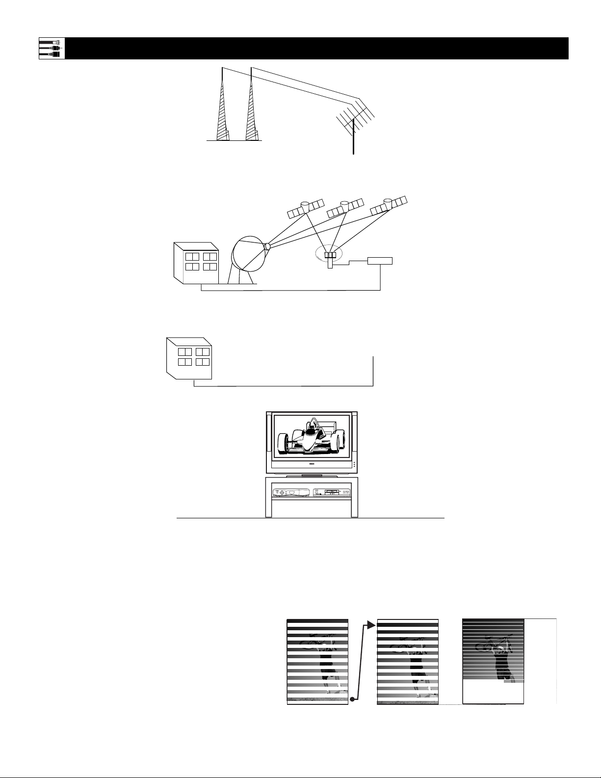
High-definition television offers a picture with unprecedented crispness and clarity. The TV broadcast industry is moving toward high definition as
the signal standard. Currently, the number of programs being broadcast in high definition is limited, but this is changing. To view high-definition programs on
your TV, you will need to connect a satellite receiver, cable box, or set-top box that can decode HD signals.
Resolution information
Image resolutions are commonly referred to by a number followed by a letter: 480i, 480p, 720p and 1080i.
The number in each format refers to the number of lines
of resolution, so for example both 480i and 480p offer
480 lines of resolution. The "i" or "p" refers to whether
the signal is displayed using respectively interlaced or
progressive scan. Interlaced scan breaks each frame of
video into 2 fields, one made up of even lines and one
made up of odd lines. The image is reproduced by drawing all odd lines first (1,3,5,…479) than all the even
ones (2,4,6,….,480). Progressive scan, on the other hand
reproduces an image by drawing all lines in succession
1,2,3,4,….480).
Interlaced Scan
Progressive Scan
Information about TV Signals
Cable TV
Company
Analog
Signal
Satellite TV
Company
Digital
Signal
Telephone Line
Cable TV Signal (Analog)
Satellite
Dish
at Your
Home
TV
Antenna
at Your
Home
Satellites
For Direct Connection
to Your TV or to a
Cable Box, VCR, or
Satellite Receiver
Satellite
Receiver
at Your
Home
DVD619 DVD/CD PLAYER
STOP
OPEN/CLOSE
GUIDE
POWER
SELECT
INFO
HIGH DEFINITION
STANDBY-ON
POWER
Odd lines Even Lines
PLAY PAUSE
PREV NEXT
Lines in succession

7
Descriptions of Jacks, Cables, and Connectors
This page contains descriptions and illustrations of jacks, cables,
and connectors you might use in making connections. The cables
and connectors are not supplied with your TV, but you can purchase at your electronics dealer. Or you can order them by calling
our Customer Care Center at 1-800-531-0039.
Antenna RF Jack
Cable Used: RF
Coaxial (75Ω)
Push-on
Type Cable
Screw-on
Type Cable
Signal Splitter
Cables Used: RF
Coaxial (75Ω)
Video (Composite) Jack
Cable Used:Video with
RCA-type Phono Plugs
Or
S-VIDEO Jack
Cable Used: S-Video
Component Video Jacks
Cables Used: Component
Video with RCA-type
Phono Plugs
Component Video Input Jacks
Cables used: component video with
RCA-type phono plugs
Allow you to connect accessory devices such
as DVD players. Separating the video into
three signals, these inputs provide excellent
quality. Accepts 480i, 480p, 720p, 1080i. Be
sure to connect the left and right audio cables,
because the Y, Pb, Pr jacks receive only the
picture signal.
NOTE: See the “Helpful Hint” on page 13
for more information.
S-Video Input Jacks
Cable used: S-Video
Provide a higher quality picture than the
Video (composite) jacks because the color
part of the picture is separated from the black
and white portion. Be sure to connect the left
and right audio cables, because the S-Video
jacks receive only the picture signal.
VGA/HD15 Jack
Cable Used: HD DB15
RGB+HV Input Connector
Cable used: HD DB15
Allows you to connect equipment with RGB
or VGA output.
Video (called “CVBS” or “compos-
ite”) Input Jack
Cable used: Video with RCA-type
phono plugs
Provide better picture performance than the
antenna RF input. Be sure to connect the
audio cables, because the video jacks receive
only the picture signal.
Your TV also has a monitor output (“MON
OUT”) video (“V”) jack. Use a video cable
with RCA-type phono plug to make connections.
Tuner (RF) Input Jack
Cables used: RF coaxial cable (75Ω)
Allows you to connect an antenna, cable TV,
or components having RF outputs to the
antenna input on the TV. RF coaxial cables
are available in push-on or screw-on type.
Audio Input Jacks
Cables used:Audio with RCA-type
phono plugs
Provide sound for the video inputs. If your
accessory device has only one output for
audio, connect it to the left (color coded
white) audio jack on the TV.
Your TV also has monitor output (“MON
OUT”) audio (“L” and “R”) jacks and a subwoofer output jack. Use Audio cables with
RCA-type phono plugs to make connections.
Audio Jacks
Cables Used:Audio
with RCA-type
Phono Plugs
Signal Splitter
Allows you to route an antenna or cable TV
signal to two inputs.
3.5mm Stereo Mini Phone
Plug to RCA Jack Adapter
Allows a connection between the
3.5mm stereo audio out jack on a computer and the left and right audio inputs
on the television. Connect A/V cables
with RCA-type phono plugs to the
adapter, then to the TV.
3.5mm Stereo Mini Phone Plug
to RCA Jack Adapter
300- to 75-ohm
Twin-lead Adapter
300- to 75-ohm Twin-lead Adapter
Accepts twin-lead wires from an antenna and
allows connection to the antenna input on the
TV. If your antenna is already equipped with
an RF coaxial cable you will not need this
adapter.
Center Channel Amp Speaker
Terminals (+ and –)
Allow a connection from a surround
sound receiver. Set the EXT/INT switch
to EXT to use the TV speakers as the
center speakers in a surround sound
arrangement.
Center Channel Amp Speaker
Terminals (for the connection
of speaker wires)
DVI-D Jack
Cables Used: DVI-D
DVI-D Input Connector
Cable used: DVI-D
This jack works only with DVI TMDS
(Transition Minimized Differential Signaling)
digital video. Allows encrypted transmissions
of uncompressed digital content. The DVI-D
jack used in this product is not for computer
connections.
DVI
Pr Pb Y
TUNER
G
S-VIDEO
RGB+HV
V
RL
INT
+
_
EXT
8
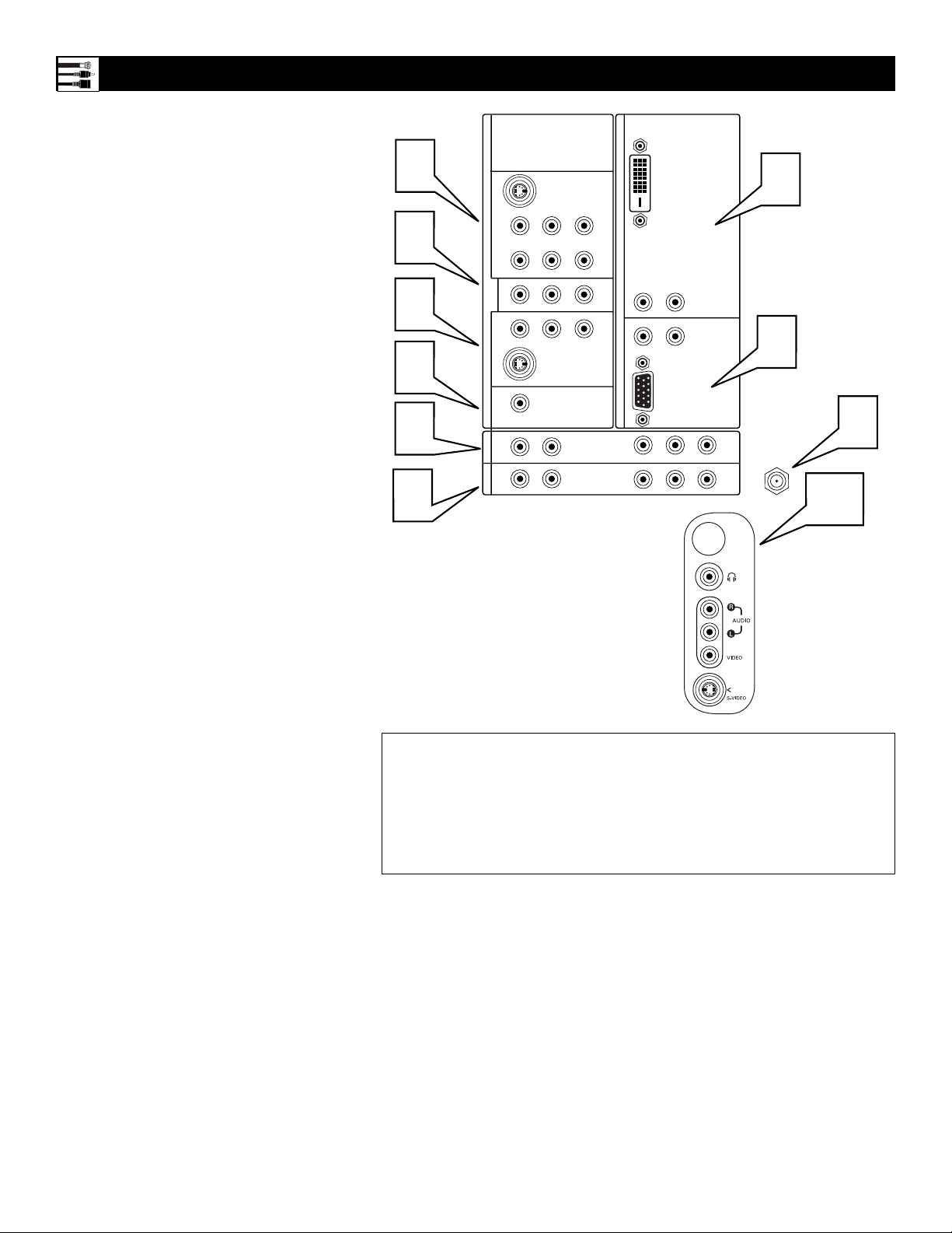
Panel Jack Compatibility Information
Speaker Terminals and EXT(ernal)/INT(ernal)
Speaker Switch Located on the Back Left Side
of the TV
Jack Panel Located
on the Left Side of
the TV
CENTER CHANNEL AMP
INPUT Click-fit Terminals
Provides speaker-wire input terminals for connection of an external
home-cinema surround-sound system amplifier. For this use, set the
switch to “EXT,” and the TV
speakers become the center speakers for the home-cinema surroundsound system.
NOTE: If no audio is heard from
the set, check to make sure the
Center Channel Amp switch is in
the INT position. This switch
should be in the EXT position
only when an external center
channel input is connected to the
Click-fit Terminals.
10
SIDE JACK PANEL
Signals accepted: Analog NTSC
(480i).
Inputs available: S-Video (Y/C)
and CVBS, plus audio left and
right.
Output available: Headphone.
Only one of the inputs can be used
at a time. Select the Side source,
and the TV detects the input to
which you have connected.
Connections must be made to the
audio inputs for sound.
11
Definitions:
NTSC—National Television System Committee.
CVBS—labeled “V,” provides a small step up in quality from the Tuner (RF) input. Called
Composite Video.
S-Video (Y/C)—provides better picture quality than CVBS. Separates the signal into color and
brightness.
YPbPr—provides the best quality video signal. Called Component Video Input, the signal is
split into three parts, two color and one brightness.
1
AV 1 Input Jacks
Signals accepted: NTSC (480i).
Inputs available: YPbPr, S-Video (Y/C), and
CVBS, plus audio left and right.
Use only one of the video signal inputs at a time.
If you should forget and have more than one type of
signal connected, the set will automatically show the
one of better quality: CVBS—good, S-Video—better, and YPbPr—best. For sound, connections must
be made to the AV1 audio inputs.
2
MON OUT Output Jacks
Provide video and audio output signals from all TV
when those sources are being viewed on the main
screen. Output from the audio L/R jacks is at a fixed
volume level; changing the TV volume does not
affect them. Adjust the volume at your external
home cinema system.
3
AV 2 Input Jacks
Signals accepted: NTSC (480i).
Inputs available: S-Video (Y/C) and CVBS, plus
audio left and right.
Use only one of the video signal inputs at a time.
If you should forget and have both types of signal
connected, the set will automatically show the
S-Video, since it is of better quality than CVBS. For
sound, connections must be made to the AV2 audio
inputs.
4
SUB OUT Output Jack
Provides a signal to an external powered subwoofer.
5
AV3 Input Jacks
Signals accepted: NTSC (480i), 480p, 720p, and
1080i, plus audio left and right.
Inputs available: YPbPr, plus audio. For sound,
connections must be made to the AV3 audio inputs.
6
AV4 Input Jacks
Signals accepted: NTSC (480i), 480p, 720p, and
1080i, plus audio left and right.
Inputs available: YPbPr, plus audio. For sound,
connections must be made to the AV4 audio inputs.
7
TUNER Input Jack
Signals accepted: RF modulated NTSC.
Inputs available: 75Ω RF coaxial.
8
AV5 Input Connector
Signals accepted: NTSC (480i), 480p, 720p, 1080i
and VG plus audio left and right.
Inputs available: RGB+HV. For sound, connections must be made to the AV5 audio inputs.
9
AV6 Input Connector
Signals accepted: Digital only (TMDS [Transition
Minimized Differential Signaling] encoded, uncom-
pressed); DVI 480i, 480p, 720p, and 1080i, plus
audio left and right.
Inputs available: DVI TMDS, plus audio. For
sound, connections must be made to the AV6 audio
inputs.
Intended use of the input: digital set-top boxes and
inputs from other digital video devices.
NOTE: This DVI jack is not for computer connections. VGA cannot be connected.
C
2
SERVICE 1
1
AV1MONSUB OUT AV2AV3AV4
G
S-VIDEO
RLV
DVI
9
2
Pr Pb Y
RL
OUT
3
RL
G
S-VIDEO
4
5
5
RL
RL
6
V
V
STANDARD/
HD INPUTS
STANDARD/
HD INPUTS
AV5 AV6
RL
RL
RGB+HV
Pr Pb Y
Pr Pb Y
8
7
TUNER
10

9
Pre-connection Recommendations
Positioning the TV
Before connecting accessory devices—VCR,
DVD player, or HD satellite receiver, for example—please keep the following in mind:
• Place the TV on a flat surface. An unlevel surface may adversely affect picture performance.
• Do not place the TV on shag carpet or any surface that will block the ventilation openings at
the bottom of the set. Blockage will cause the
TV to overheat and shut down.
• Allow 4 to 6 inches of space behind the TV
for ventilation.
• An optional swivel and an optional stand are
available for use with your TV. See your electronics dealer.
• Test various locations in the room to find the
optimal spot to locate the set for best viewing.
• Do not place the TV in direct sunlight or near
a heating appliance.
• Do not expose the TV to rain or moisture.
• To prevent any unsafe situations, do not place
objects on top of the TV.
Providing Protection Against Power
Surges
• Connect all accessory devices before you plug
any of their power cords into the wall outlet or
power strip. NEVER plug your TV into an
outlet that is controlled by a wall switch.
• Turn off the TV and/or accessory devices
before you connect or disconnect any cables.
• Ensure that all antennas and cables are properly grounded. See page 3, “Important Safety
Instructions.”
Protecting Accessory Devices from
Overheating
• Arrange accessory devices so that air can circulate freely around them.
• Don’t stack the accessory devices. Arrange
them to allow for good ventilation. The
optional Philips stand provides enough room
for two accessory devices, side by side.
• If you connect an audio receiver or amplifier,
place it on the top shelf so the heated air from
it will not flow around other components.
Connecting Cables
Be sure to insert each cable firmly into the correct jack.
Using the Connection Examples in
This Manual
The accessory device jack panels shown are for
example purpose only. The jack panels on your
accessory devices may look different. Also, note
that connections can be made in various ways.
The examples are presented only as guides.
Allow 4 to 6 inches
behind the TV for
ventilation.
Place the TV on
a flat surface.
Do not place the TV on a surface that will block
the air filters located underneath the set.
Situate the TV where
it will not be exposed
to heat or moisture.
For safety, do not
set objects on top
of the TV.
Optional Swivel
Optional Stand
DVD619 DVD/CD PLAYER
GUIDE
POWER
POWER
SELECT
INFO
HIGH DEFINITION
STANDBY-ON
STOP
OPEN/CLOSE
PLAY PAUSE
PREV NEXT

10
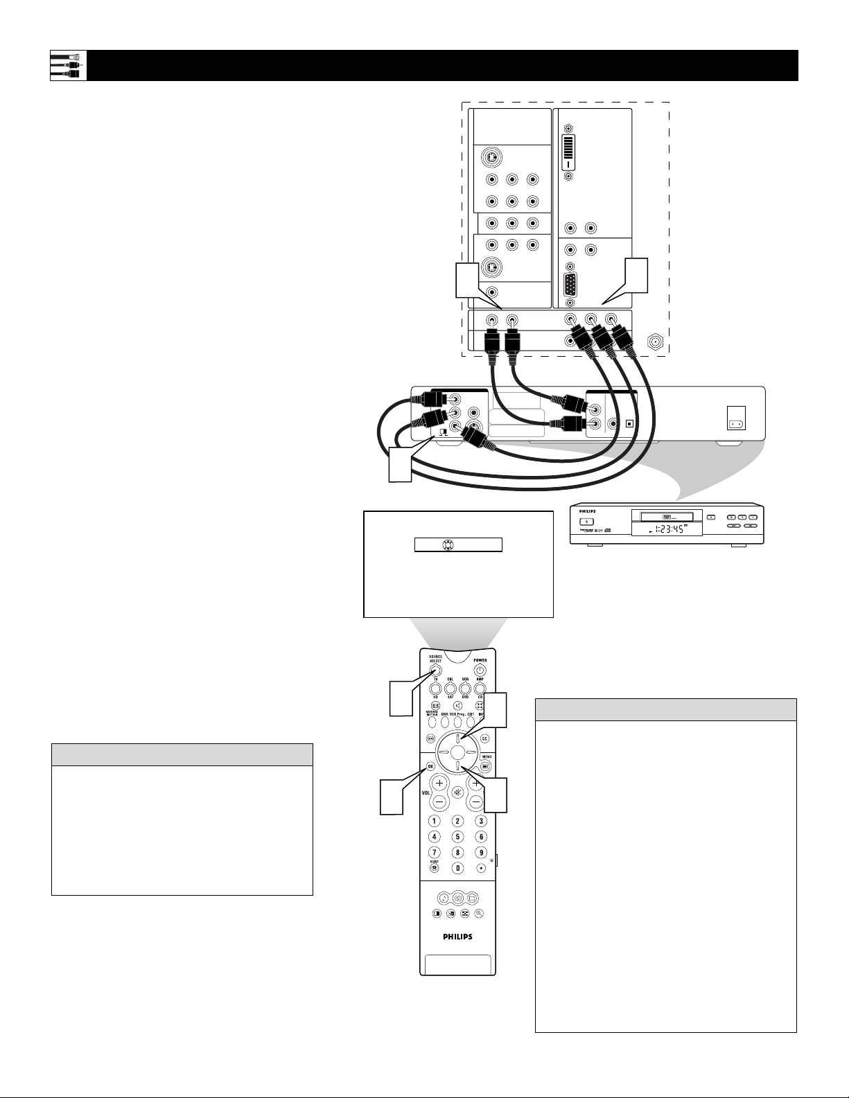
Connecting a VCR
Back of TV
Incoming Cable TV
or Antenna Signal
Back of VCR
(example only)
1
Connect the incoming antenna or cable
TV signal to the ANT IN jack on the
back of the VCR.
2
Using a coaxial cable, connect to the
OUT jack on the back of the VCR and
to the TUNER jack on the back of the
TV.
3
Using A/V cables, connect from the
AUDIO and VIDEO OUT jacks on the
back of the VCR to the corresponding
AV2 audio (L and R) and video (V)
jacks on the back of the TV.
4
Press the Source Select button on the
remote control to access the Source
list.
5
Press the Cursor Up or Down button to
select the AV2 input source.
6
Press the OK button to confirm your
choice. The set is now switched to the
AV2 input source for the viewing of programs from the VCR.
NOTE: Since you’ve connected the
cable TV signal directly to the TV’s
tuner (step 2 above), you can watch the
unscrambled programs by simply tuning to the desired channel. To store
channels in the TV’s memory, you
must use Autoprogram, which you can
access through “Install” in the TV’s
on-screen menu. See the Autoprogram
section in the Quick Use and Setup
Guide that came with the TV. If you
use Autoprogram, you can select channels by pressing the CH + or – buttons
on the TV remote control (in TV
mode). Otherwise, you must press the
digit (number) buttons to tune directly
to the channel you desire.
Color Coding Used on Jacks and Plugs to
simplify connections:
Yellow: Video (Composite Video)
Red: Right Audio
White: Left Audio.
HELPFUL HINT
Source
C
2
SERVICE 1
DVI
3
V
RL
RL
V
AV5 AV6
RGB+HV
Pr Pb Y
Pr Pb Y
AUDIO
L
ANT
OUT
IN
OUT
R
VIDEO
IN
CH3 CH4
IN
OUT
2
TUNER
AV1MONSUB OUT AV2AV3AV4
OUT
G
S-VIDEO
RLV
Pr Pb Y
RL
RL
G
S-VIDEO
RL
STANDARD/
HD INPUTS
STANDARD/
HD INPUTS
RL
TV
AV1:Other
OK
AV2:Other
AV3:Other
AV4:Other
AV5:Other
AV6:Other
SIDE
:Other
1
6
4
ACITVE
CONTROL
SOUND PICTURE
1 2
5
5
ZOOM

11
Connecting a VCR and Cable Box
Back of TV
Incoming
Cable TV
Signal
Back of VCR
(example only)
Back of Cable Box (example only)
Signal
Splitter
NOTE: A cable box with AUDIO OUT jacks
such as the one used in the example on this
page might pass stereo sound to the TV. Check
with your cable TV company. The RF jack output jack on a cable box (commonly labeled
“OUT TO TV,” “OUTPUT,” or “OUT”) will
not pass stereo sound to your TV.
1
Connect the incoming cable TV signal
to a two-way signal splitter. The signal
splitter enables you to route the cable
signal to the TV without using the
OUT TO TV jack on the cable box,
which will not pass stereo sound to the
TV.
2
Using a coaxial cable, connect to one
of the connectors on the signal splitter
and to the TUNER jack on the back of
the TV.
3
Using a coaxial cable, connect to the
other connector on the signal splitter
and to the CABLE IN jack on the back
of the cable box.
4
Using Audio/Video cables, connect to
the AUDIO and VIDEO OUT jacks on
the back of the cable box and to the
corresponding AUDIO and VIDEO IN
jacks on the back of the VCR.
5
Using Audio/Video cables, connect to
the AUDIO and VIDEO OUT jacks on
the back of the VCR and to the corresponding AV2 audio (L and R) and
video (V) input jacks on the back of
the TV.
6
Press the Source Select button on the
remote control to access the Source
list.
7
Press the Cursor Up or Down button to
select the AV2 input source.
8
Press the OK button to confirm your
choice. The set is now switched to the
AV2 input source for the viewing of programs from the cable box or the VCR.
NOTE: Since you’ve connected the
cable TV signal directly to the TV’s
tuner (step 2 above), you can watch
the unscrambled programs by simply tuning to the desired channel. To
store channels in the TV’s memory,
you must use Autoprogram, which
you can access through “Install” in
the TV’s on-screen menu. See the
Autoprogram section in the Quick
Use and Setup Guide that came with
the TV. If you use Autoprogram,
you can select channels by pressing
the CH + or – buttons on the TV
remote control (in TV mode).
Otherwise, you must press the digit
(number) buttons to tune directly to
the channel you desire.
Color Coding Used on Jacks and Plugs to
simplify connections:
Yellow: Video (Composite Video)
Red: Right Audio
White: Left Audio.
HELPFUL HINT
Source
6
2
C
SERVICE 1
AV1MONSUB OUT AV2AV3AV4
OUT
G
S-VIDEO
RLV
Pr Pb Y
RL
V
V
RL
G
S-VIDEO
RL
STANDARD/
HD INPUTS
STANDARD/
HD INPUTS
RL
5
AV5 AV6
DVI
RL
RL
RGB+HV
Pr Pb Y
2
Pr Pb Y
1
TUNER
4
AUDIO
L
ANT
OUT
IN
OUT
R
VIDEO
IN
CH3 CH4
IN
OUT
TV
AV1:Other
OK
AV2:Other
AV3:Other
AV4:Other
AV5:Other
AV6:Other
SIDE
:Other
3
OUTPUT
CH
CABLE
IN
3 4
TO
TV
VIDEO
OUT
RL
AUDIO
OUT
7
8
ACITVE
CONTROL
SOUND PICTURE
1 2
7
ZOOM

12
Connecting an S-Video Device
Back of Standard S-Video Device
(example only)
Back of TV
1
Using an S-Video cable, connect to the
S-Video output on the back of the
S-Video device and to the AV2 SVIDEO input.
2
Using Stereo Audio cables, connect to
the AUDIO OUT jacks on the back of
the S-Video device and to the corresponding AV2 audio inputs (L and R).
3
Press the Source Select button on the
remote control to access the Source
list.
4
Press the Cursor Up or Down button to
select the AV2 input source.
5
Press the OK button to confirm your
choice. The set is now switched to the
AV2 input source for the viewing of programs from the S-Video device.
To simplify making connections, the connectors on audio and video cables are often color
coded to match the colors on TV jacks, red for
right, and white for left.
HELPFUL HINT
2
1
OK
Source
TV
AV1:Other
AV2:Other
AV3:Other
AV4:Other
AV5:Other
AV6:Other
SIDE
:Other
2
C
SERVICE 1
AV1MONSUB OUT AV2AV3AV4
OUT
G
S-VIDEO
RLV
Pr Pb Y
RL
V
V
RL
G
S-VIDEO
RL
STANDARD/
HD INPUTS
STANDARD/
HD INPUTS
RL
DVI
RL
RL
AV5 AV6
RGB+HV
Pr Pb Y
L R
AUDIO OUT
TUNER
VIDEO
ANT/CABLE
OUT
IN
Pr Pb Y
S-VIDEO
OUT
5
3
ACITVE
CONTROL
SOUND PICTURE
1 2
4
4
ZOOM

13
Connecting a Standard DVD Player
Back of TV
Back of Standard DVD Player
(example only)
1
Using Component Video cables, connect to the YPbPr jacks on the back of
the standard DVD player and to the
AV1 YPbPr jacks on the back of the
TV.
2
Using Stereo Audio cables, connect to
the AUDIO OUT jacks on the back of
the DVD player and to the corresponding AV1 audio (L and R) jacks on the
back of the TV.
3
Press the Source Select button on the
remote control to access the Source
list.
4
Press the Cursor Up or Down button to
select the AV1 input source.
5
Press the OK button to confirm your
choice. The set is now switched to the
AV1 input source for the viewing of programs from the DVD player.
• If you do not know whether your DVD
player is standard or progressive scan, you
can connect it to either AV3 or AV4, and the
TV will automatically determine the type of
output.
• To simplify making connections, the connectors on audio and video cables are often
color coded to match the colors on TV
jacks: green for Y, blue for Pb, and red for
Pr; also red for right audio, and white for
left audio.
• The names for the component video jacks
may differ depending on the DVD player or
accessory digital source equipment used.
For example, besides YPbPr, you may see
R-Y/B-Y/Y; or CrCbY. Although abbreviations and terms may vary, the letters B and
R stand for the blue and red color component signal connectors, respectively, and Y
indicates the luminance signal. If necessary,
refer to the user manual for your DVD or
digital accessory for more information.
• If you experience difficulties receiving
sound with a DVD disc, check the sound
settings through the DVD disc’s menu.
HELPFUL HINTS
3
5
Source
1 2
2
2
TV
AV1:Other
OK
AV2:Other
AV3:Other
AV4:Other
AV5:Other
AV6:Other
SIDE
ACITVE
CONTROL
SOUND PICTURE
C
SERVICE 1
AV1MONSUB OUT AV2AV3AV4
OUT
PCM-MPEG2-Dolby Digital-DTS
COAXIAL
:Other
4
4
ZOOM
DIGITAL AUDIO OUT
G
S-VIDEO
RLV
Pr Pb Y
RL
V
V
RL
G
S-VIDEO
RL
STANDARD/
HD INPUTS
STANDARD/
HD INPUTS
RL
SUB WF OUT
OPT OUT
DVI
1
RL
RL
AV5 AV6
RGB+HV
Pr Pb Y
Pr Pb Y
1
2
L
R
AUDIO OUT
DVD619 DVD/CD PLAYER
STANDBY-ON
TUNER
1
2
PR/C
(CVBS)
VIDEO OUT
R
Y
P
B/CB
VIDEO OUT
OPEN/CLOSE
(Y/C)
S-VIDEO OUT
STOP
PREV NEXT
PLAY PAUSE
14
1
Using Component Video cables, connect
to the YPbPr jacks on the back of the
progressive-scan DVD player and to the
AV3 YPbPr jacks on the back of the TV.
2
Using Stereo Audio cables, connect to
the AUDIO OUT jacks on the back of
the DVD player and to the corresponding AV3 audio (L and R) jacks on the
back of the TV.
3
If your DVD player has an I/P switch
on the back, be sure it is set to the “P”
position for progressive-scan mode.
NOTE: Some DVD players have an I/P
switch on the back, while others may
allow the user to change the mode by
pressing a button on the DVD player’s
remote control or by using the DVD
player’s on-screen menu. Also, some
DVD players have dedicated progressive-scan output jacks that are labeled
as such and require no switching by the
user. See the user manual for your DVD
player for more information on placing
the player in progressive-scan mode.
4
Press the Source Select button on the
remote control to access the Source
list.
5
Press the Cursor Up or Down button to
select the AV3 input source.
6
Press the OK button to confirm your
choice. The set is now switched to the
AV3 input source for the viewing of programs from the DVD player.
Connecting a Progressive-scan DVD Player
Back of TV
Back of Progressive-
scan DVD Player
(example only)
• To simplify making connections, the connectors on audio and video cables are often
color coded to match the colors on TV
jacks: green for Y, blue for Pb, and red for
Pr; also red for right audio, and white for
left audio.
• The names for the component video jacks
may differ depending on the DVD player or
accessory digital source equipment used.
For example, besides YPbPr, you may see
R-Y/B-Y/Y; or CrCbY. Although abbreviations and terms may vary, the letters B and
R stand for the blue and red color component signal connectors, respectively, and Y
indicates the luminance signal. If necessary,
refer to the user manual for your DVD or
digital accessory for more information.
• If you experience difficulties receiving
sound with a DVD disc, check the sound
settings through the DVD disc’s menu.
HELPFUL HINTS
Inputs AV3–AV6 allow horizontal and vertical
picture panning using the Cursor Left, Right,
Up, and Down buttons. The Side input allows
vertical picture panning; left and right panning
with the Side input is possible when the input
has been labeled “Game.” See pages 18 and 19
for details on side panel connections and
source labeling.
HELPFUL HINT
3
Source
C
2
SERVICE 1
G
S-VIDEO
RLV
AV1MONSUB OUT AV2AV3AV4
Pr Pb Y
RL
OUT
RL
G
S-VIDEO
2
RL
STANDARD/
HD INPUTS
STANDARD/
HD INPUTS
RL
VIDEO OUT
Y
VIDEO
B
P
PR
SELECT
I
S
P
DVI
V
RL
RL
V
AV5 AV6
RGB+HV
Pr Pb Y
Pr Pb Y
1
TUNER
AUDIO OUT
2CH
BITSTREAM
/PCM
L
R
OPTICAL
COAXIAL
DIGITAL
AC IN ~
DVD619 DVD/CD PLAYER
--AV2:Other
OK
AV3:Other
AV4:Other
AV5:Other
AV6:Other
SIDE
:Other
STANDBY-ON
OPEN/CLOSE
PLAY PAUSE
STOP
PREV NEXT
6
4
ACITVE
CONTROL
SOUND PICTURE
1 2
5
5
ZOOM

15
1
Using Component Video cables, connect to the YPbPr jacks on the back of
the HD satellite receiver and to the corresponding AV4 YPbPr jacks on the
back of the TV.
2
Using Stereo Audio cables, connect to
the AUDIO OUT jacks on the back of
the HD satellite receiver and to the corresponding AV4 audio (L and R) jacks
on the back of the TV.
3
Refer to the user manual for the HD
satellite receiver to complete the connections to the HD satellite receiver
and to use the HD satellite receiver’s
on-screen setup menus.
4
After completing HD satellite receiver
connections and setup through the onscreen setup menus, press the Source
Select button on the TV remote to
access the Source list.
5
Press the Cursor Up or Down button to
select the AV4 input source.
6
Press the OK button to confirm your
choice. The set is now switched to the
AV4 input source for the viewing of programs from the HD satellite receiver.
Connecting an HD Satellite Receiver to YPbPr
Back of TV
Back of HD
Receiver
(example only)
• To simplify making connections, the connectors on audio and video cables are often
color coded to match the colors on TV
jacks: green for Y, blue for Pb, and red for
Pr; also red for right audio, and white for
left audio.
• The names for the component video jacks
may differ depending on the DVD player or
accessory digital source equipment used.
For example, besides YPbPr, you may see
R-Y/B-Y/Y; or CrCbY. Although abbreviations and terms may vary, the letters B and
R stand for the blue and red color component signal connectors, respectively, and Y
indicates the luminance signal. If necessary,
refer to the user manual for your DVD or
digital accessory for more information.
• Inputs AV3–AV6 allow horizontal and vertical picture panning using the Cursor Left,
Right, Up, and Down buttons. The Side
input allows vertical picture panning; left
and right panning with the Side input is possible when the input has been labeled
“Game.” See pages 18 and 19 for details on
side panel connections and source labeling.
HELPFUL HINTS
2
OK
Source
RF
REMOTEPHONE JACK
--AV3:Other
AV4:Other
AV5:Other
AV6:Other
SIDE:Other
C
2
SERVICE 1
AV1MONSUB OUT AV2AV3AV4
OUT
Y
PB
PR
G
S-VIDEO
RLV
Pr Pb Y
RL
RL
G
S-VIDEO
RL
STANDARD/
HD INPUTS
STANDARD/
HD INPUTS
RL
AUDIO
AUDIO
L
L
RR
VIDEOVIDEO
V
V
CONTROL
VCR
S-VIDEO
AV5 AV6
HIGH DEFINITION
DVI
RL
RL
RGB+HV
Pr Pb Y
Pr Pb Y
DIGITAL
AUDIO OUT
POWER
SELECT
1
TUNER
OUT TO TV
CH 3
CH 4
IN FROM ANT SATELLITE IN
GUIDE
POWER
INFO
6
4
ACITVE
CONTROL
SOUND PICTURE
1 2
3
User Manual
for
5
HD Satellite
Receiver
5
ZOOM

16
1
Using a DVI cable, connect to the DVI
jack on the back of the HD satellite
receiver and to the corresponding AV6
DVI jack on the back of the TV.
2
Using Stereo Audio cables, connect to
the AUDIO OUT jacks on the back of
the HD satellite receiver and to the
corresponding AV6 audio (L and R)
jacks on the back of the TV.
3
Refer to the user manual for the HD
satellite receiver to complete the connections to the HD satellite receiver
and to use the HD satellite receiver’s
on-screen setup menus.
4
After completing HD satellite receiver
connections and setup through the onscreen setup menus, press the Source
Select button on the TV remote to
access the Source list.
5
Press the Cursor Up or Down button to
select the AV6 input source.
6
Press the OK button to confirm your
choice. The set is now switched to the
AV6 input source for the viewing of
programs from the HD satellite receiver.
Connecting an HD Satellite Receiver to DVI
Back of TV
Back of HD satellite receiver
(example only)
• To simplify making connections, the connectors on audio cables are often color
coded to match the colors on TV jacks: red
for right audio, and white for left audio.
• Because DVI is such new technology, the
electronics industry is still working
toward a decision on one standard.
Philips testing has determined that compatibility issues exist with respect to a
limited number of high-definition
receivers when they are connected to the
DVI input on this television. If you
should experience difficulties, please
contact our Customer Care Center at 1800-531-0039.
• Inputs AV3–AV6 allow horizontal and vertical picture panning using the Cursor Left,
Right, Up, and Down buttons. The Side
input allows vertical picture panning; left
and right panning with the Side input is
possible when the input has been labeled
“Game.” See pages 18 and 19 for details on
side panel connections and source labeling.
HELPFUL HINTS
AIR IN
SATELLITE IN
DIGITAL OUT
CABLE IN
OK
Source
DOLBY
(OPTICAL)
--AV5:Other
AV6:Other
SIDE:Other
2
RESOLUTION SELECT
1080i 720p 480p/i
C
SERVICE 1
AV1MONSUB OUT AV2AV3AV4
OUT
G
S-VIDEO
RLV
Pr Pb Y
RL
V
V
RL
G
S-VIDEO
RL
STANDARD/
HD INPUTS
STANDARD/
HD INPUTS
RL
ACCESS CARD
DVI/HDCP OUT
1
DVI
2
RL
RL
AV5 AV6
RGB+HV
Pr Pb Y
Pr Pb Y
DTV OUTPUT SELECT
RGB/Y PB P
R
DVI
RGB OUT
TV OUT
TUNER
VIDEO OUT
1
L1
R1
CH
AUDIO OUT
3 4
DOLBY
COMPONENT
DIGITAL
OUT
2
(COAXIAL)
Y
P
B
L2
AUDIO
P
R
R2
U
L
®
LISTED
VCR
E207602
CONTROL
7H74
AUDIO/VIDEO PRODUCT
Lt
TEL LINE
Rt
S-VIDEO
4
6
5
ACITVE
CONTROL
SOUND PICTURE
1 2
3
User Manual
for
5
ZOOM
HD Satellite
Receiver

17
1
Using speaker wires, connect to the
Center Speaker output terminals
(+, –) on the back of the surround
sound receiver and to the corresponding (+, –) CENTER CHANNEL
AMP terminals on the back of the TV.
2
Set the CENTER CHANNEL AMP
INPUT switch to EXT. This allows
the TV cabinet speakers to be used
as the center speakers in a surround
sound arrangement.
3
Using Stereo Audio cables, connect
to the MON OUT L and R jacks on
the back of the TV and to the corresponding TV IN jacks on the back of
the receiver.
4
Using an Audio cable, connect to the
SUB OUT jack on the back of the
TV and to the Audio Input jack on
the back of a powered subwoofer.
5
Using speaker wires, connect to the
R and L Front Speakers terminals
and to the corresponding terminals
on the backs of the front speakers.
6
Using speaker wires, connect to the
Surround Speakers terminals (+, –)
on the back of the receiver and to the
corresponding terminals (+, –) on the
back of the surround speakers.
7
Press the Menu button on the remote
control to display the on-screen
menu.
8
Press the Cursor Down button to
select “Settings.”
9
Press the Cursor Right button to
select “General.”
10
Press the Cursor Down button
repeatedly until “Subwoofer” is
selected.
11
Press the Cursor Right or Left button
to select “Yes.”
Connecting Surround Sound Equipment
Back of TV
Back of Receiver
(example only)
Surround
(Back)
Speakers
Front
Speakers
Powered
Subwoofer
“Yes” must be activated for the Subwoofer
menu selection before the SUB OUT jack
will supply output. This is because the subwoofer’s low frequencies are redirected to the
main TV speakers when “No” is selected.
H
ELPFUL HINT
To simplify making connections,
the connectors on audio cables are
often color coded to match the colors on TV jacks: red for right audio,
and white for left audio.
H
ELPFUL HINT
3
C
2
SERVICE 1
DVI
G
S-VIDEO
RLV
AV1MONSUB OUT AV2AV3AV4
Pr Pb Y
RL
V
RL
OUT
RL
RL
V
G
S-VIDEO
AV5 AV6
RGB+HV
Pr Pb Y
RL
STANDARD/
HD INPUTS
TUNER
Pr Pb Y
STANDARD/
HD INPUTS
RL
C
2
SERVICE 1
G
S-VIDEO
RLV
AV1MONSUB OUT AV2AV3AV4
Pr Pb Y
RL
OUT
RL
G
S-VIDEO
Audio
Input
180
Phase
0
RL
RL
4
STANDARD/
HD INPUTS
STANDARD/
HD INPUTS
DVI
V
RL
RL
V
AV5 AV6
RGB+HV
Pr Pb Y
Pr Pb Y
TUNER
4
+-
+
-
6
8
Settings
Daylight saving
Change PIN
Subwoofer
Lamp rating
Lamp replaced
9
General
No • Yes
1
7
9
5
General
Settings
Daylight saving
Change PIN
Subwoofer
Lamp rating
Lamp replaced
Yes • No

18
Connecting to the Side Inputs: Video Game System
Panel on
Side of
TV
Back of Game System
(example only)
You can label the Side
Audio/Video input source “Game”
if you would like. See page 19 for
details on labeling.
• To simplify making connections, the connectors on audio and video cables are
often color coded to match the colors on
TV jacks: yellow for video (composite),
red for right audio, and white for left
audio.
• Inputs AV3–AV6 allow horizontal and vertical picture panning using the Cursor Left,
Right, Up, and Down buttons. The Side
input allows vertical picture panning; left
and right panning with the Side input is
possible when the input has been labeled
“Game.” See page 19 for details on source
labeling.
HELPFUL HINTS
1
Using the Audio/Video cable supplied
with your video game system, connect
to the back of the game system and to
the corresponding S-VIDEO and
AUDIO (L and R) jacks in the Side
panel of the TV.
NOTE: If your game system cable
does not have an S-Video plug, you
can instead make a regular Video
connection.
2
Press the Source button on the TV
remote control to access the Source
list.
3
Press the Cursor Up or Down button to
select the Side input source.
4
Press the OK button to confirm your
choice. The set is now switched to the
Side input source for the viewing of
your video game system.
The side panel is also
convenient for connecting equipment
such as camcorders or
cameras. If the equipment has an S-Video
output jack, it is the
suggested one to use for your connection to
receive the best picture. Otherwise, you can
make a regular Video connection. You must
also make an audio connection (L and R for
stereo or L for mono) to receive sound.
Neither an S-Video or Video cable carries a
sound signal.
Camcorder
1
--AV6:Other
OK
Source
SIDE:Other
2
3
4
3
ACITVE
CONTROL
SOUND PICTURE
1 2
ZOOM

19
Labeling the Audio/Video Input Sources
You can label all the external Audio/Video
input sources—AV1, AV2, AV3, AV4, AV5,
AV6, and Side—according to the type of
accessory device you have connected to each
input.
After labeling, you can use the Source Select
button to cycle through and select your
desired source. The labels will appear alongside the channel indicator when you select the
AV input sources.
1
Press the Menu button on the remote
control to display the on-screen menu.
2
Press the Cursor Down button to select
“Settings.”
3
Press the Cursor Right button repeatedly to select the “Source” menu.
4
Press the Cursor Down button repeatedly to select any of the AV Inputs—
AV1, AV2, AV3, AV4, AV5, AV6, or
Side. A list of labels will appear next to
the selected AV input.
5
Press the Cursor Right button to enter
the list.
6
Press the Cursor Up or Down button to
scroll and select one of the labels in the
list.
7
Press the Menu button on the remote
control to remove the on-screen menu
from the TV screen.
8
Press the Source Select button on the
remote control to display the list of AV
inputs and their labels.
This is just a sample of what the
labeling might look like. Your
Source Labels will depend on the
options you choose to label the
AV inputs.
Settings
Demo
Install
8
Picture Sound Features Channels
TV
6
2
3
5
1
Settings
Settings
Settings
TV
Demo
Install
AV1
AV2
AV3
AV4
AV1
AV2
AV3
AV4
General Clock Source
Source
Source
--Other
8
4
6
ACITVE
CONTROL
SOUND PICTURE
1 2
TV
AV1:DVD
AV2:Recorder
AV3:SAT
AV4:HD
AV5:Other
AV6:HD
OK
Source
SIDE:Camera
ZOOM
7
Settings
Settings
Source
--Other
AV1
Source
---
AV1
DVD
SAT
Recorder
PVR
Other

20
Source Select
Press to display a list of input source options—TV, AV1, AV2,
AV3–AV6, or Side. Use the Cursor Up/Down buttons to select the an
item, then press the OK button to confirm. The source becomes active
on the TV screen.
Mode ( TV, CBL,VCR,AMP, HD, SAT, DVD, or CD)
Press one of these buttons to use the remote control in the TV, CBL, VCR,
or AMP mode as indicated above the button. A green indicator lights up.
Press the same button again more than 1 second to use the remote control
in the mode indicated below the button (HD, SAT, DVD, or CD). A red
indicator lights up. Press the button again more than 1 second to return to
the function named above the button. (See pages 22–23 in the Directions
for Use.)
Picture Format
Press to display a list of available picture formats. Press this button repeatedly to select another picture format. Choose from Automatic, Super
zoom, Panoramic, 4:3, Movie expand 14:9, Movie expand 16:9, 16:9 subtitle, and Wide screen. (See pages 35–36 in the Directions for Use.)
NOTES:
• With AV3–AV6 connections, the Automatic picture format option is not
available.
• In Dual-screen mode, press the Picture Format button to switch between
a full or 4:3 letterbox picture format.
Natural Motion™
This button is not applicable to the Cineos Television. Select the Digital
Natural Motion™ option through the on-screen menu. (See page 30 in the
Directions for Use.)
Freeze Format
Pressing will apply one of the Freeze modes.
NOTE: The Freeze mode must be set using the TV’s on-screen menu.
Freeze mode stops action in the main screen. Sound will continue to be
heard. Press again to resume normal viewing.
Replay mode displays a few seconds of stored video in the
PIP window.
Photo Finish mode displays six stored frames from the picture.
Continuing to hold the Freeze Format button down will cycle the TV
through the Freeze modes: Freeze, Replay, and Photo Finish.
(See page 61 in the Directions for Use.)
DNR (Dynamic Noise Reduction)
Press this button repeatedly to select Off, Minimum, Medium, or
Maximum. (See page 32 in the Directions for Use.)
OK
Press to activate your choice or to confirm settings when in the menus.
Volume (VOL)
Press + or – to adjust the volume.
Mute
Press to interrupt or restore sound.
Surf (AutoSurf™)
If you set the Surf control in the TV’s on-screen menu to two channels,
this button will allow you to toggle between the current channel and the
last viewed channel. If you choose the nine-channel Surf, pressing this
button allows you to add and scroll up to nine of your favorite channels.
(See page 58 in the Directions for Use.)
VCR/DVD
When the remote is in the VCR or DVD mode, these buttons will allow
you start a recording (
●), rewind a tape (), stop the playback of a
tape (
■), play a videotape (), fastforward a videotape (), use the
VCR timer (
y), or pause the playback of a videotape (❙ ❙)
. (See page 26
in the Directions for Use.)
Sound (AutoSound™)
Press to select the next item in the AutoSound™ menu. The factory-set
options are Speech, Music, Movies, and Multimedia, each corresponding
with specific settings of treble and bass. You can also select the Personal
option, which is based on the adjustments you make through the Sound
menu. (See page 46 in the Directions for Use.)
REMOTE CONTROL BUTTONS
MultiPIP
The first press
of this button
displays PIP3
(the default
option). A long
press of the
button cycles
through PIP3
and PIP6.
Another press
turns PIP off.
PIP Swap
Press to swap
the main picture
with the PIP
window picture,
or to swap the
left and right
screens when in
Dual Screen PIP
mode. Press
again to restore
pictures to their
original position.
Dual
Screen/PIP
Press to turn the
PIP dual screen
on or off.Press
and hold the button to cycle
through the Dual
Screen/PIP
options. (See
pages 58–59 in
the Directions
for Use.)
ACITVE
CONTROL
SOUND PICTURE
ZOOM

21
Power–Standby
Press to turn the TV on or off. NOTE: The TV is never powered off completely unless it is unplugged.
Alternate Audio
When you tune to a channel where SAP (Second Audio Program) is available, you can toggle between Main and SAP. If not available, only Main can
be selected. (See page 42 in the Directions for Use.)
Surround Sound
Press to toggle the sound modes Incredible Surround™ and Dolby* Virtual.
(See page 41 in the Directions for Use.)
VCR Prog (functional only in VCR mode)
Many VCRs have an automatic programming function. If your VCR has this
function, the universal code set will assign it to this function. (See page 26 in
the Directions for Use.)
INFO +
Press to display (when available) information about the current channel, program, source, number or name, local time, CC availability, SAP availability,
program ratings, display format, sound mode, and remaining length of a
Sleeptimer setting.
EXIT
Press this button to exit the menus provided by universal devices such as
VCRs, satellite receivers, DVD players, and so forth.
CC (Closed Captioning)
Press to select On, Off, or On with Mute. (See page 47 in the Directions for
Use.)
Cursor Up, Down, Right, and Left
Use to navigate the on-screen menu and make control adjustments or settings.
Additionally, use these buttons to pan the screen up or down to show any
excluded parts of the picture. Left or right panning is possible with the Side
input source when “Game” is selected as the type of source for the Side input.
(See page 18 in the Directions for Use manual.)
Also use with the Dual Screen/PIP feature to select a screen or reposition a
PIP screen.
Menu
Press to display the TV’s on-screen menu or to turn it off.
CH (Channel Selection)
Press to browse through the TV channels.
Digit (Number Buttons)
Press to directly access a specific TV channel. For a two- or three-digit channel, enter all numbers. Press a single-digit button and hold for 1 second to
directly access a single-digit channel. These buttons can also be used to enter
values in certain on-screen menu controls.
Backlight
Press this button on the right side of the remote control. The backlighting of
the buttons VOL, CH,
H, and the digit buttons stays on for 5 seconds after
pressing the button.
Picture (AutoPicture™)
Press to select the next item in the AutoPicture™ menu. The factory-set
options are Rich, Natural, Soft, Multimedia, and Eco, each corresponding with
specific factory settings of Contrast, Color, Sharpness, DNR, Dynamic
Contrast, and Color enhancements. You can also select the Personal option,
which is based on the adjustments or settings you make through the Picture
menu. (See page 34 in the Directions for Use.)
Zoom
NOTE: Zooming is disabled in Dual Screen mode.
Press the Zoom button to activate the zoom function. Press the OK button
repeatedly to select one of the zoom magnifications (1x, 4x, 9x, or 16x).
Additionally, you can shift the selected zoom window over the screen with the
Cursor Up, Down, Left, or Right buttons. The zoom window is reset after
selecting another TV channel, another picture format, or when another display
format is selected automatically. Press the Zoom button again to turn off the
zoom function. (See page 28 in the Directions for Use.)
Active Control™ Plus
NOTE: Active Control™ Plus is not available for use with the AV3, AV4,
AV5, and AV6 input sources.
Press to toggle the options Off, Minimum, Medium, and Maximum.
Maximum is the recommended option. (See page 27 in the Directions for
Use.)
Active Control, AutoPicture, AutoSound, AutoSurf, Incredible Surround,
and Natural Motion are trademarks of Philips Consumer Electronics.
Copyright 2003 Philips Consumer Electronics. All rights reserved.
REMOTE CONTROL BUTTONS
ACITVE
CONTROL
SOUND PICTURE
ZOOM

22
PROGRAMMING THE TV REMOTE TO OPERATE ACCESSORY DEVICES
The remote control supplied with your television
may also work with a variety of infrared-controlled accessory devices such as cable boxes,
VCRs, amplifiers, HD satellite receivers, satellite
receivers, DVD players, and CD players.
1
Press the CBL, VCR, AMP, HD, SAT,
DVD, or CD Mode button, depending
on the type of accessory device you
want to operate. If the function buttons—Play, CH + or –, Stop, for example—on the remote control work the
device, the remote is ready to use and
no further steps are required.
If the remote does not work with the
accessory device, proceed to step 2.
Using the Code Entry Method
Please look up the code(s) for your brand of
accessory device (listed on pages 24–25)
before you begin the next few steps.
2
Press the desired Mode button that corresponds to the type of device you
wish to operate—CBL, VCR, AMP,
HD, SAT, DVD, or CD. A green light
will indicate the mode labeled on the
top of the button, while a red light will
indicate the mode labeled on the bottom of the button. If needed, hold the
button down and the light will toggle
between the green and red settings.
3
Press and hold the 1 and 3 Digit
(Number) buttons at the same time until
the Backlight and selected Mode buttons light up. Then release both buttons.
4
Within 30 seconds of completing step 3
and using the Digit (Number) buttons,
enter the four-digit code from pages
24–25 for your brand of device. Several
codes may be listed for your brand, so
you may need to try them all before the
remote will operate the device.
If a valid code number has been entered, the
Backlight and Mode buttons will turn off and
then blink twice. The remote control will
assign that code number to the mode selected.
Try the function buttons to see if the remote
will operate your accessory device.
If yes, no other steps are required.
If no, try the procedure again with another code
number listed by your brand. Several attempts
may be needed to complete all code numbers.
If none of the codes work, please refer to
page 23 to try the Auto Search Method.
CBL
VCR
DVD
SAT
AMP
STANDBY-ON
HIGH DEFINITION
POWER
2
SELECT
DVD619 DVD/CD PLAYER
GUIDE
POWER
INFO
OPEN/CLOSE
PLAY PAUSE
STOP
PREV NEXT
2
ACITVE
CONTROL
SOUND PICTURE
1 2
3
ZOOM

23
The Auto Search Method of programming the
remote control can take several minutes to
complete. So before starting, it is recommended that you sit in a comfortable position at
least six feet from the accessory device. You
will have to hold the remote so that it is
pointed at the front of the device for the entire
time the search is taking place.
1
Turn the accessory device on using the
device’s power button.
2
Press the desired Mode button that corresponds to the type of device you
wish to operate—CBL, VCR, AMP,
HD, SAT, DVD, or CD. A green light
will indicate the mode labeled on the
top of the button, while a red light will
indicate the mode labeled on the bottom of the button. If needed, hold the
button down and the light will toggle
between the green and red settings.
3
Press and hold the 1 and 3 Digit
(Number) buttons at the same time until
the Backlight and selected Mode buttons light up. Then release both buttons.
4
Press and release the red POWER button on the remote control. The
Backlight buttons and the selected
Mode button will turn off.
The remote will start the Auto Search of all
available codes, sending a command to channel up. The backlight will blink after each
code is tried. For devices such as DVD or CD
players, insert a disc and press PLAY on the
device. The remote control will send a command to switch to the next track. Switch AV
receivers to the tuner function.
IMPORTANT: Watch the channel indicator
of your accessory device closely. Once the
right code is found, the channels on your
device will start to scan up.
5
Press and release the red POWER button on the remote control as soon as
the channels start to change. The
Backlight buttons and selected Mode
button will blink twice to indicate the
Auto Search code setup is complete.
NOTE: If any other buttons are pressed during the procedure, the Auto Search will end.
Remember, Auto Search can take several minutes to complete, so please be patient.
PROGRAMMING THE TV REMOTE TO OPERATE ACCESSORY DEVICES
1
HIGH DEFINITION
POWER
GUIDE
SELECT
POWER
07
INFO
08
09
06
07
08
09
06
07
08
09
2
3
ACITVE
CONTROL
SOUND PICTURE
1 2
4
5
ZOOM

24
S
ETUP CODES FOR
ACCESSORY DEVICES
Amplifier
Aiwa . . . . . . . . . . . . . . . . . . . . . . . . . . . .0433
Carver . . . . . . . . . . . . . . . . . . . . . . . . . . .0296
Curtis Mathes . . . . . . . . . . . . . . . . . . . . .0327
Denon . . . . . . . . . . . . . . . . . . . . . . . . . . .0187
GE . . . . . . . . . . . . . . . . . . . . . . . . . . . . .0105
Harman/Kardon . . . . . . . . . . . . . . . . . . . .0919
JVC . . . . . . . . . . . . . . . . . . . . . . . . . . . . .0358
Linn . . . . . . . . . . . . . . . . . . . . . . . . . . . . .0296
Magnavox . . . . . . . . . . . . . . . . . . . . . . . .0296
Marantz . . . . . . . . . . . . . . . . . . . . .0296, 0348
Nakamichi . . . . . . . . . . . . . . . . . . . . . . . .0348
Optimus . . . . . . . . . . . . . . . . . . . . . . . . . .0422
Panasonic . . . . . . . . . . . . . . . . . . . . . . . .0335
Philips . . . . . . . . . . . . . . . . . . . . . .0296, 0919
Pioneer . . . . . . . . . . . . . . . . . . . . .0040, 0327
Realistic . . . . . . . . . . . . . . . . . . . . . . . . .0422
Sansui . . . . . . . . . . . . . . . . . . . . . . . . . . .0348
Sony . . . . . . . . . . . . . . . . . . . . . . .0716, 0247
Soundesign . . . . . . . . . . . . . . . . . . . . . . .0105
Technics . . . . . . . . . . . . . . . . . . . . . . . . .0335
Victor . . . . . . . . . . . . . . . . . . . . . . . . . . . .0358
Wards . . . . . . . . . . . . . . . . . . . . . .0040, 0105
Yamaha . . . . . . . . . . . . . . . . . . . . . . . . . .0381
Cable Box
ABC . . . . . . . . .0030, 0028, 0034, 0035, 0038,
. . . . . . . . . . . . . . . . . . . . . .0040, 0041, 0044
Allegro . . . . . . . . . . . . . . . . . . . . . .0180, 0342
Americast . . . . . . . . . . . . . . . . . . . . . . . .0926
Antronix . . . . . . . . . . . . . . . . . . . . . . . . . .0049
Archer . . . . . . . . . . . . . . . . .0049, 0180, 0824
Belcor . . . . . . . . . . . . . . . . . . . . . . . . . . .0083
Bell & Howell . . . . . . . . . . . . . . . . . . . . . .0041
Cable Star . . . . . . . . . . . . . . . . . . . . . . . .0083
Cabletenna . . . . . . . . . . . . . . . . . . . . . . .0049
Cableview . . . . . . . . . . . . . . . . . . . . . . . .0049
Century . . . . . . . . . . . . . . . . . . . . . . . . . .0180
Citizen . . . . . . . . . . . . . . . . . . . . . .0180, 0342
Colour Voice . . . . . . . . . . . . . . . . . . . . . .0052
Comtronics . . . . . . . . . . . . . . . . . . . . . . .0067
Contec . . . . . . . . . . . . . . . . . . . . . . . . . .0046
Eastern . . . . . . . . . . . . . . . . . . . . . . . . . .0029
Emerson . . . . . . . . . . . . . . . . . . . . . . . . .0824
Everquest . . . . . . . . . . . . . . . . . . .0042, 0067
Focus . . . . . . . . . . . . . . . . . . . . . . . . . . .0427
GC Electronics . . . . . . . . . . . . . . . . . . . .0083
Garrard . . . . . . . . . . . . . . . . . . . . . . . . . .0180
Gemini . . . . . . . . . . . . . . . . . . . . . . . . . .0042
General Instrument . . .0303, 0503, 0038, 0837
GoldStar . . . . . . . . . . . . . . . . . . . .0067, 0171
Goodmind . . . . . . . . . . . . . . . . . . . . . . . .0824
Hamlin . . . . . . . . . . . .0047, 0036, 0286, 0061
Hitachi . . . . . . . . . . . . . . . . . . . . . . . . . . .0038
Hytex . . . . . . . . . . . . . . . . . . . . . . . . . . . .0034
Jasco . . . . . . . . . . . . . . . . . .0042, 0180, 0342
Jerrold . . . . . . . . . . . .0030, 0039, 0303, 0041,
. . . . . . . . . . . . . . . . .0038, 0503, 0042, 0837
Memorex . . . . . . . . . . . . . . . . . . . . . . . . .0027
Movie Time . . . . . . . . . . . . . . . . . . . . . . .0090
NSC . . . . . . . . . . . . . . . . . . . . . . . . . . . .0090
Oak . . . . . . . . . . . . . . . . . . . . . . . .0046, 0034
Optimus . . . . . . . . . . . . . . . . . . . . . . . . . .0048
Panasonic . . . . . . . . . . . . . .0048, 0134, 0027
Paragon . . . . . . . . . . . . . . . . . . . . . . . . .0027
Philips . . . . . . . . . . . . . . . . . . . . . .0052, 0180
Pioneer . . . . . . . . . . . . . . . .0171, 0560, 0904
Popular Mechanics . . . . . . . . . . . . . . . . .0427
Pulsar . . . . . . . . . . . . . . . . . . . . . . . . . . .0027
Quasar . . . . . . . . . . . . . . . . . . . . . . . . . .0027
RCA . . . . . . . . . . . . . . . . . . . . . . . . . . . .0048
Radio Shack . . . . . . . .0042, 0342, 0910, 0824
Recoton . . . . . . . . . . . . . . . . . . . . . . . . . .0427
Regal . . . . . . . . . . . . . . . . . . . . . . .0047, 0286
Regency . . . . . . . . . . . . . . . . . . . . . . . . .0029
Rembrandt . . . . . . . . . . . . . . . . . . . . . . .0038
Runco . . . . . . . . . . . . . . . . . . . . . . . . . . .0027
SL Marx . . . . . . . . . . . . . . . . . . . . . . . . . .0067
Samsung . . . . . . . . . . . . . . . . . . . .0067, 0171
Scientific Atlanta . . . . .0035, 0044, 0504, 0904
Signal . . . . . . . . . . . . . . . . . . . . . .0042, 0067
Signature . . . . . . . . . . . . . . . . . . . . . . . . .0038
Sprucer . . . . . . . . . . . . . . . . . . . . . . . . . .0048
Starcom . . . . . . . . . . . . . . . . . . . . .0030, 0042
Stargate . . . . . . . . . . . . . . . .0067, 0042, 0824
Starquest . . . . . . . . . . . . . . . . . . . . . . . . .0042
Sylvania . . . . . . . . . . . . . . . . . . . . . . . . .0028
TV86 . . . . . . . . . . . . . . . . . . . . . . . . . . . .0090
Tandy . . . . . . . . . . . . . . . . . . . . . . . . . . .0285
Teleview . . . . . . . . . . . . . . . . . . . . . . . . .0067
Texscan . . . . . . . . . . . . . . . . . . . . . . . . . .0028
Tocom . . . . . . . . . . . . . . . . . . . . . .0039, 0040
Toshiba . . . . . . . . . . . . . . . . . . . . . . . . . .0027
Tusa . . . . . . . . . . . . . . . . . . . . . . . . . . . .0042
Unika . . . . . . . . . . . . . . . . . . . . . . .0180, 0049
United Artists . . . . . . . . . . . . . . . . . . . . . .0034
Universal . . . . . . . . . .0049, 0083, 0180, 0218
Viewstar . . . . . . . . . . . . . . . . . . . . .0285, 0090
Zenith . . . . . . . . . . . . . . . . . .0027, 0552, 0926
Zentek . . . . . . . . . . . . . . . . . . . . . . . . . . .0427
CD Player
Aiwa . . . . . . . . . . . . . . . . . . . . . . . . . . . .0184
Burmester . . . . . . . . . . . . . . . . . . . . . . . .0447
California Audio Labs . . . . . . . . . . . . . . . .0056
Carver . . . . . . . . . . . . . . . . .0184, 0206, 0464
DKK . . . . . . . . . . . . . . . . . . . . . . . . . . . .0027
Denon . . . . . . . . . . . . . . . . . . . . . .0030, 0900
Emerson . . . . . . . . . . . . . . . . . . . . . . . . .0332
Fisher . . . . . . . . . . . . . . . . . . . . . .0201, 0206
Garrard . . . . . . . . . . . . . . . . . . . . .0420, 0447
Genexxa . . . . . . . . . . . . . . . . . . . .0059, 0332
Harman/Kardon . . . . . . . . . . . . . . .0200, 0184
Hitachi . . . . . . . . . . . . . . . . . . . . . . . . . . .0059
JVC . . . . . . . . . . . . . . . . . . . . . . . . . . . . .0099
Kenwood . . . . . . . . . .0055, 0217, 0853, 0064,
. . . . . . . . . . . . . . . . . . . . . . . . . . .0653, 0708
Krell . . . . . . . . . . . . . . . . . . . . . . . . . . . .0184
LXI . . . . . . . . . . . . . . . . . . . . . . . . . . . . .0332
Linn . . . . . . . . . . . . . . . . . . . . . . . . . . . . .0184
MCS . . . . . . . . . . . . . . . . . . . . . . . . . . . .0056
MTC . . . . . . . . . . . . . . . . . . . . . . . . . . . .0447
Magnavox . . . . . . . . . . . . . . . . . . .0184, 0332
Marantz . . . . . . . . . . . . . . . .0184, 0056, 0207
Mission . . . . . . . . . . . . . . . . . . . . . . . . . .0184
NSM . . . . . . . . . . . . . . . . . . . . . . . . . . . .0184
Nikko . . . . . . . . . . . . . . . . . . . . . . . . . . . .0201
Onkyo . . . . . . . . . . . . . . . . . . . . . .0128, 0895
Optimus . . . . . . . . . . .0447, 0059, 0206, 0495,
. . . . . . . . . . . . .0464, 0332, 0027, 0064, 0172
Panasonic . . . . . . . . . . . . . . . . . . .0056, 0330
Parasound . . . . . . . . . . . . . . . . . . . . . . . .0447
Philips . . . . . . . . . . . . . . . . . . . . . .0184, 0653
Pioneer . . . . . . . . . . . .0059, 0495, 0271, 0332
Proton . . . . . . . . . . . . . . . . . . . . . . . . . . .0184
QED . . . . . . . . . . . . . . . . . . . . . . . . . . . .0184
Quasar . . . . . . . . . . . . . . . . . . . . . . . . . .0056
RCA . . . . . . . . . . . . . .0080, 0332, 0206, 0791
Realistic . . . . . . . . . . . . . . . .0206, 0207, 0447
Rotel . . . . . . . . . . . . . . . . . . . . . . .0184, 0447
SAE . . . . . . . . . . . . . . . . . . . . . . . . . . . .0184
Sansui . . . . . . . . . . . . . . . . . . . . . .0184, 0332
Sanyo . . . . . . . . . . . . . . . . . . . . . . . . . . .0206
Scott . . . . . . . . . . . . . . . . . . . . . . . . . . . .0332
Sears . . . . . . . . . . . . . . . . . . . . . . . . . . .0332
Sharp . . . . . . . . . . . . . . . . . .0064, 0207, 0888
Sherwood . . . . . . . . . . . . . . . . . . . . . . . .0207
Sony . . . . . . . . . . . . . . . . . .0027, 0212, 0517
Soundesign . . . . . . . . . . . . . . . . . . . . . . .0172
Tascam . . . . . . . . . . . . . . . . . . . . . . . . . .0447
Teac . . . . . . . . . . . . . .0420, 0447, 0201, 0207
Technics . . . . . . . . . . . . . . . . . . . .0330, 0056
Victor . . . . . . . . . . . . . . . . . . . . . . . . . . . .0099
Wards . . . . . . . . . . . . . . . . . . . . . .0080, 0184
Yamaha . . . . . . . . . . . . . . . . . . . . .0214, 0063
Yorx . . . . . . . . . . . . . . . . . . . . . . . . . . . . .0488
Surround Sound Receiver
ADC . . . . . . . . . . . . . . . . . . . . . . . . . . . .0558
Adcom . . . . . . . . . . . . . . . . . . . . . . . . . . .0643
Aiwa . . . . . . . . . . . . . .0148, 0432, 0185, 0216
Akai . . . . . . . . . . . . . . . . . . . . . . . .0251, 0103
Capetronic . . . . . . . . . . . . . . . . . . . . . . . .0558
Carver . . . . . . . . . . . .0035, 0216, 0387, 0069
Casio . . . . . . . . . . . . . . . . . . . . . . . . . . . .0222
Clarinette . . . . . . . . . . . . . . . . . . . . . . . . .0222
Curtis Mathes . . . . . . . . . . . . . . . . . . . . .0107
Denon . . . . . . . . . . . . . . . . .0031, 0798, 0300
Emerson . . . . . . . . . . . . . . . . . . . . . . . . .0451
Fisher . . . . . . . . . . . . . . . . . .0069, 0246, 0387
Garrard . . . . . . . . . . . . . . . . . . . . .0451, 0490
Harman/Kardon . . . . . . . . . .0137, 0216, 0918
Inkel . . . . . . . . . . . . . . . . . . . . . . . . . . . .0089
JBL . . . . . . . . . . . . . . . . . . . . . . . . . . . . .0137
JVC . . . . . . . . . . . . . . . . . . . . . . . . . . . . .0101
Kenwood . . . . . . . . . .0054, 0341, 0104, 0069,
. . . . . . . . . . . . . . . . . . . . . . . . . . .0213, 0340
Koss . . . . . . . . . . . . . . . . . . . . . . . . . . . .0451
LXI . . . . . . . . . . . . . . . . . . . . . . . . . . . . .0208
Linn . . . . . . . . . . . . . . . . . . . . . . . . . . . . .0216
Lloyd's . . . . . . . . . . . . . . . . . . . . . . . . . . .0222
MCS . . . . . . . . . . . . . . . . . . . . . . .0066, 0373
Magnavox . . . . .0216, 0418, 0558, 0155, 0222
Marantz . . . . . . . . . . . . . . . .0216, 0155, 0066
Modulaire . . . . . . . . . . . . . . . . . . . . . . . .0222
NAD . . . . . . . . . . . . . . . . . . . . . . . . . . . .0347
NEC . . . . . . . . . . . . . . . . . . . . . . . . . . . .0262
Nakamichi . . . . . . . . . . . . . . . . . . .0374, 0124
Onkyo . . . . . . . . . . . . . . . . .0162, 0407, 0127
Optimus . . . . . . . . . . .0208, 0204, 0213, 0246,
. . . . . . . . . . . . .0558, 0765, 0828, 0069, 0697
Panasonic . . . . . . . . . . . . . .0066, 0336, 0545
Penney . . . . . . . . . . . . . . . . . . . . . . . . . .0222
Philips . . . . . . . . . . . . . . . . . . . . . .0216, 0418
Pioneer . . . . . . .0107, 0041, 0177, 0558, 0657
Quasar . . . . . . . . . . . . . . . . . . . . . . . . . .0066
RCA . . . . . . . . .0081, 0373, 0558, 0387, 0557
Realistic . . . . . . . . . . . . . . .0208, 0222, 0190
Sansui . . . . . . . . . . . . . . . . .0216, 0220, 0373
Sanyo . . . . . . . . . . . . . . . . . . . . . .0246, 0828
Scott . . . . . . . . . . . . . . . . . . . . . . .0190, 0349
Sharp . . . . . . . . . . . . . . . . . . . . . . . . . . .0213
Sherwood . . . . . . . . . . . . . . .0529, 0518, 0089
Sony . . . . . . . . . . . . . . . . . .0185, 0195, 0501
Soundesign . . . . . . . . . . . . . . . . . . . . . . .0697
Teac . . . . . . . . . . . . . . . . . . . . . . .0490, 0190
Technics . . . . . . . . . . .0336, 0066, 0235, 0545
Victor . . . . . . . . . . . . . . . . . . . . . . . . . . . .0101
Wards . . . . . . . .0081, 0041, 0107, 0185, 0216
Yamaha . . . . . . . . . . . . . . . . . . . . .0203, 0213
Yorx . . . . . . . . . . . . . . . . . . . . . . . . . . . . .0222
Zenith . . . . . . . . . . . . . . . . . . . . . . . . . . .0884
 Loading...