

Philips 43FDX01B, PDP42X3 Series Service Manual
Published by MW 0765 BG CD Customer Service Printed in the Netherlands Subject to modification EN 3122 785 16392
©
Copyright 2007 Philips Consumer Electronics B.V. Eindhoven, The Netherlands.
All rights reserved. No part of this publication may be reproduced, stored in a
retrieval system or transmitted, in any form or by any means, electronic,
mechanical, photocopying, or otherwise without the prior permission of Philips.
Colour Television Module
LGE PDP 2K6
PDP42X3*
Contents Page
1. Technical Specifications, Connections, and Chassis
Overview 2
2. Safety Instructions, Warnings, and Notes 5
3. Directions for Use 6
4. Mechanical Instructions 7
5. Service Modes, Error Codes, and Fault Finding 12
6. Block Diagrams, Test Point Overviews, and
Waveforms 25
7. Circuit Diagrams and PWB Layouts 25
8. Alignments 26
9. Circuit Descriptions, Abbreviation List, and IC Data
Sheets 29
10. Spare Parts List 34
11. Revision List 34
Technical Specifications, Connections, and Chassis Overview
EN 2 LGE PDP 2K61.
1. Technical Specifications, Connections, and Chassis Overview
Index of this chapter:
1.1 Technical Specifications PDP42X3*
1.1.1 General Specification
1.1.2 Definitions
1.1.3 Chassis Overview
1.1 Technical Specifications PDP42X3*
The PDP Module is divided into a Panel part and a Drive part.
The Panel part consists of Electrodes, Phosphor, various
dielectrics, and gas, while the Drive part includes electronic
circuitry and PWBs.
1.1.1 General Specification
Table 1-1 General Specifications
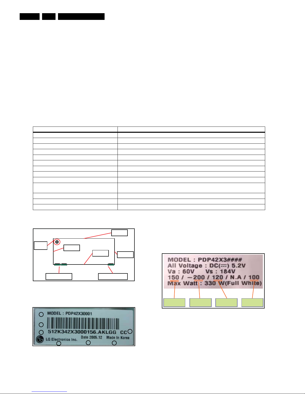
1.1.2 Definitions
Figure 1-1 Definition of module position
Figure 1-2 Identification label
1. Model name.
2. Bar code (Code 128, contains the manufacture no.).
3. Manufacture no. (Module serial no.).
4. The trade name of LG Electronics.
5. Manufacture date (Year & Month).
6. The place of origin.
7. Model suffix.
Figure 1-3 Voltage label (on rear side of module)
Model Name
PDP42X3*
Number Of Pixels (H x V)
1024 (*3) x 768
Pixel Pitch (H x V µm) 900 x 676
Cell Pitch (H x V µm)
300 x 676 (base: Green Cell)
Display Area (H x V mm) 921.6 x 519.2 ± 0.5
Outline Dimension (H x V x D mm) 1005 x 597 x 61.2 ± 1
Colour Arrangement RGB closed type
Number Of Colours (R x G x B) 1024 x 1024 x 1024 (1,073,741,824)
Weight 15.3 ± 0.5 kg
Aspect Ratio 16 : 9
Peak Brightness
Typical 1200 cd/m
2
(1 % white window)
Average 140 : 1 (Light room 100 Lx at centre)
Contrast Ratio Typical 10000 : 1 (Dark room 1 % white window, white window pattern at centre)
Power Consumption Max. 330 W (Full White)
Lifetime Over 60,000 hours (initial brightness 1/2)
G_16390_001.eps
290607
t s u a h x E
e l o h
1 g n o l
2 g n o l
1 t r o h s
2 t r o
h s
g 2-1 n o l P C
T
• •
• • •
• •
•
2
2 - 2 g n o l P C T
e l u d o m f o e d i s Rear *
G_16390_002.eps
020806
1
2
3
4
5
6
7
c
s V
y
V -
p u t e s V b z V
G_16391_001.eps
290607
Technical Specifications, Connections, and Chassis Overview
EN 3LGE PDP 2K6 1.
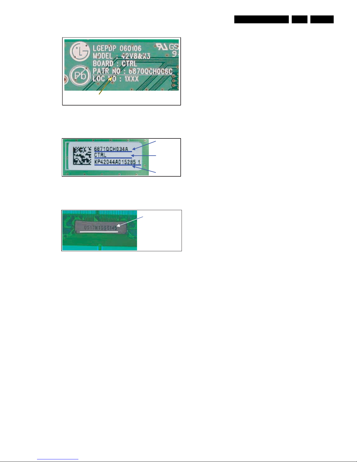
Figure 1-4 Part number printing (on board)
Figure 1-5 Part number label (on board)
Figure 1-6 TCP serial number (on TCP)
PCB PART NO.
G_16390_008.eps
040806
G_16390_005.eps
020806
BOARD
SERIAL NR.
BOARD
NAME
BOARD ASSY
PART NR.
G_16390_007.eps
030806
TCP SERIAL NO.
Technical Specifications, Connections, and Chassis Overview
EN 4 LGE PDP 2K61.
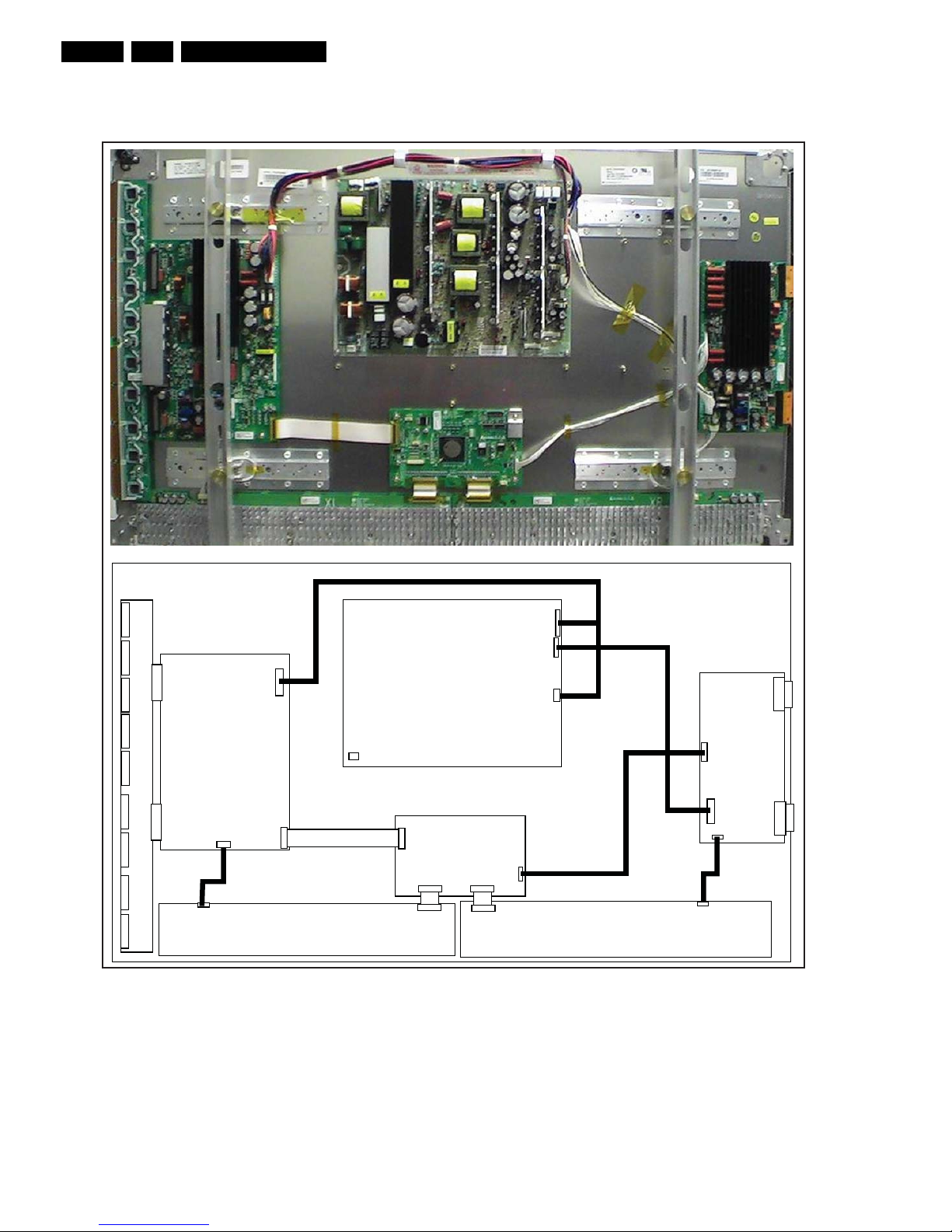
1.1.3 Chassis Overview
Figure 1-7 PWB location
G_16391_002.eps
290607
Control
Board
Z Sus
Board
Y Sus
Board
X Right Board
X Left Board
Y Driver Board
PSU
3501Q00203B

Safety Instructions, Warnings, and Notes
EN 5LGE PDP 2K6 2.
2. Safety Instructions, Warnings, and Notes
Index of this chapter:
2.1 Warnings
Notes:
• Only authorised persons should perform servicing of this
module.
• When using/handling this unit, pay special attention to the
PDP Module: it should not be enforced into any other way
then next rules, warnings, and/or cautions.
• "Warning" indicates a hazard that may lead to death or
injury if the warning is ignored and the product is handled
incorrectly.
• "Caution" indicates a hazard that can lead to injury or
damage to property if the caution is ignored and the
product is handled incorrectly.
2.1 Warnings
1. Do not touch the Signal and Power Connectors while this
product operates. Do not touch EMI ground part and Heat
Sink of Film Filter.
2. Do not supply a voltage higher than specified to this
product. This may damage the product or can create
hazardous situations.
3. Do not use this product in locations where the humidity is
extremely high, where it may be splashed with water, or
where flammable materials surround it. Do not install or
use the product in a location that does no satisfy specified
environmental conditions. This may damage the product or
can create hazardous situations.
4. If a foreign substance (such as water, metal, or liquid) gets
inside the product, immediately turn "OFF" the power.
Continuing to use the product may cause electric shock or
can create hazardous situations.
5. If the product emits smoke and abnormal smell, or makes
an abnormal sound, immediately turn "OFF" the power.
Continuing to use the product may cause electric shock or
can create hazardous situations.
6. Do not (dis)connect the connector while power to the
product is "ON". It takes some time for the voltage to drop
to a sufficiently low level after the power has been turned
"OFF". Confirm that the voltage has dropped to a safe level
before (dis)connecting the connector.
7. Do not pull out or insert the power cable from/to an outlet
with wet hands. It may cause electric shock.
8. Do not damage or modify the power cable. It may cause
electric shock or can create hazardous situations.
9. If the power cable is damaged, or if the connector is loose,
do not use the product, otherwise, this can lead to
hazardous situations or may cause electric shock.
10. If the power connector, or the connector of the power
cable, is dirty or dusty, wipe it with a dry cloth. Otherwise,
this can lead to hazardous situations.
11. The PDP module uses a high voltage (max. 450 V
DC
).
Keep the cautions concerning electric shock and do not
touch the device circuitry handling the PDP unit. And
because the capacitors of the device circuitry may remain
charged at the moment of Power "OFF", standing for 1
minute is required in order to touch the device circuitry.
12. Because the PDP module emits heat from the glass panel
part and the drive circuitry, the environmental temperature
must not be over 40 deg. C. The temperature of the glass
panel part is especially high owing to heat from internal
drive circuitry. And because the PDP module is driven by
high voltage, it must avoid conductive materials.
13. If inserting components or circuit boards in order to repair,
be sure to fix a lead line to the connector before soldering.
14. If inserting high-power resistors (metal-oxide film resistor
or metal film resistor) in order to repair, insert it 10 mm
away from a board.
15. During repairs, high voltage or high temperature
components must be put away from a lead line.
16. This is a cold chassis but you better use an isolation
transformer for safety during repairs. If repairing the
electricity source part, you MUST use the isolation
transformer.
17. Do not place an object on the glass surface of the display.
The glass may break or be scratched.
18. This product may be damaged if it is subjected to
excessive stresses (such as excessive voltage, current, or
temperature). The absolute maximum ratings specify the
limits of these stresses.
19. The recommended operating conditions are conditions in
which the normal operation of this product is guaranteed.
All the rated values of the electrical specifications are
guaranteed within these conditions. Always use the
product within the range of the recommended operating
conditions. Otherwise, the reliability of the product may be
degraded.
20. This product has a glass display surface. Design your
system so that excessive shock and load are not applied to
the glass. Exercise care that the vent at the corner of the
glass panel is not damaged. If the glass panel or vent is
damaged, the product is inoperable.
21. Do not cover or wrap the product with a cloth or other
covering while power is supplied to the product.
22. Before turning on power to the product, check the wiring of
the product and confirm that the supply voltage is within the
rated voltage range. If the wiring is wrong or if a voltage
outside the rated range is applied, the product may
malfunction or be damaged.
23. Do not store this product in a location where temperature
and humidity are high. This may cause the product to
malfunction. Because this product uses a discharge
phenomenon, it may take time to light (operation may be
delayed) when the product is used after it has been stored
for a long time. In this case, it is recommended to light all
cells for about 2 hours (aging).
24. This product is made from various materials such as glass,
metal, and plastic. When discarding it, be sure to contact a
professional waste disposal operator.
25. If faults occur due to arbitrary modification or disassembly,
LG Electronics is not responsible for function, quality or
other items.
26. Use of the product with a combination of parameters,
conditions, or logic not specified in the specifications of this
product is not guaranteed. If intending to use the product in
such a way, be sure to consult LGE in advance.
27. Within the warranty period, general faults that occur due to
defects in components such as ICs will be rectified by LGE
without charge. However, IMAGE STICKING due to
misapplying the above provision (12), is not included in the
warranty. Repairs due to the other faults may be charged
for depending on responsibility for the faults.
28. While assembling the PDP module into a set, use the EMI
ground part of the Film Filter for grounding, BEFORE
removing the protective film, to prevent that static electricity
can damage the TCPs or boards

Directions for Use
EN 6 LGE PDP 2K63.
3. Directions for Use
Not applicable.
Mechanical Instructions
EN 7LGE PDP 2K6 4.
4. Mechanical Instructions
Index of this chapter:
4.1 Mechanical Overviews
4.2 Panel/assy removal
4.2.1 Power Supply Unit
4.2.2 Control Board
4.2.3 Y Sustain Board
4.2.4 Y Driver Board
4.2.5 Z-Sustain board
4.2.6 X-board
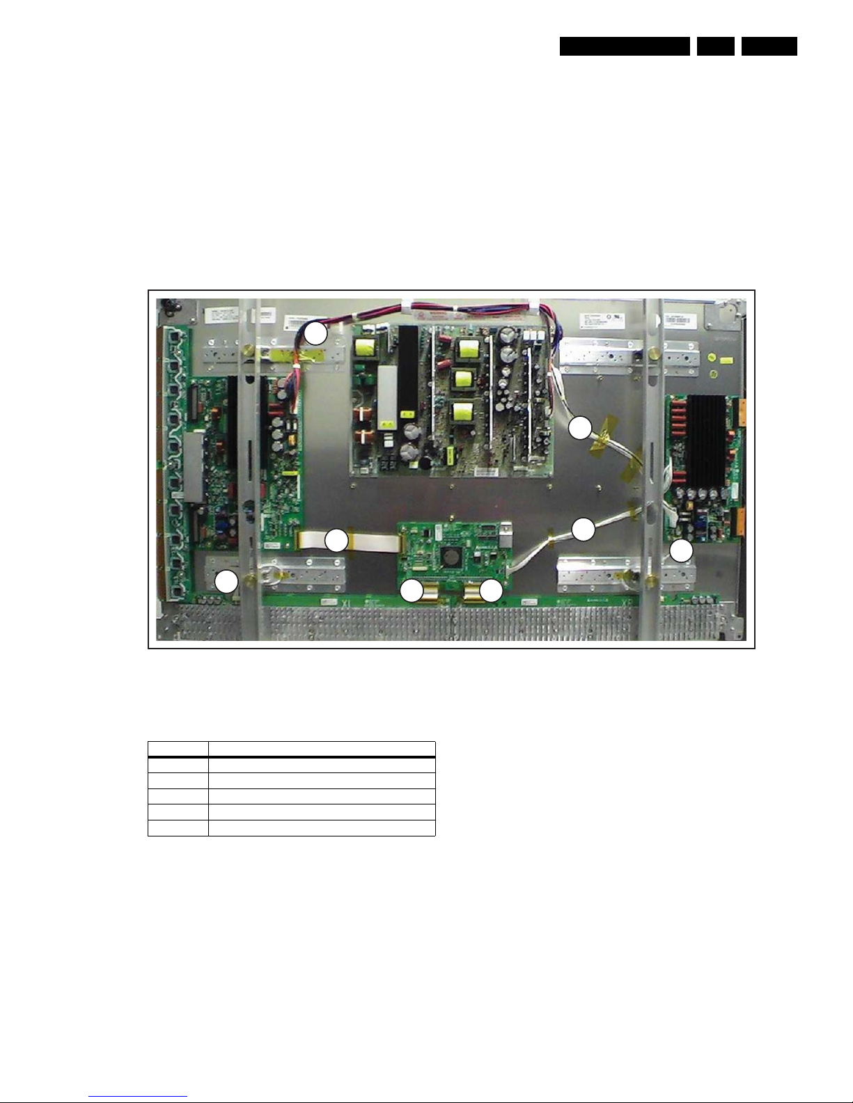
4.1 Mechanical Overviews
Figure 4-1 Cable dressing
Table 4-1 Cable function
G_16391_004.eps
020707
8
4
1
2 3
6
5
7
Cable No. Function
1 Drive signal for Y waveform
2 & 3 RGB data to be transferred to panel
4 & 5 5V and Va supply for X-boards Left and Right
6 Drive signal for Z-waveform
7 & 8 Va, Vs and 5 V supply for PDP operation

Mechanical Instructions
EN 8 LGE PDP 2K64.
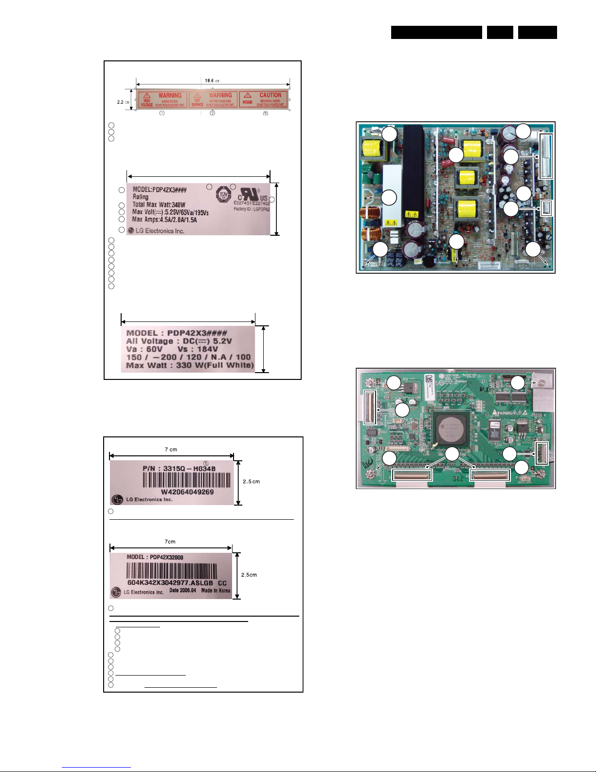
Figure 4-2 Label location on PWB’s
Figure 4-3 Label indication
G_16390_014.eps
070806
G_16390_013.eps
070806
Mechanical Instructions
EN 9LGE PDP 2K6 4.
Figure 4-4 Label information (1)
Figure 4-5 Label information (2)
4.2 Panel/assy removal
4.2.1 Power Supply Unit
1. Unplug the connectors [1].
2. Remove the fixation screws [2].
Figure 4-6 PSU removal
4.2.2 Control Board
1. Unplug the connectors [1].
2. Remove the fixation screws [2].
Figure 4-7 Control board removal
1. Warning & Caution Label : Warning and caution for High Voltage, Hot Surface, Wound
1 Warning (High Voltage, Hazard Voltage)
2 Warning (Hot Surface, Hot part)
3 Caution (Wound, Mechanical Hazard)
2. Safety Approval Label
8
67
5
4
3
2
1
2.5 cm
7 cm
1 Model Name
2 Max. Watt (Full White)
3 Max. Volts
4 Max. Amps
5 The Trade Name of LG Electronics
6 TUV Approval Mark
7 Safety Approval Mark
8 Safety Approval No.
3. Voltage Label : Model Name & Operational Voltage
2.5 ?
7 cm
G_16390_020.eps
020707
4. Serial No. for Frame Ass’y
1 Serial No of Frame Ass’y
Serial No. of Frame Ass’y for Philips are 3315Q-E037B, 3315Q-E037C and 3315Q-E037F .
5. Manufacture Serial No. Label of Module
1 Model Name
Model Names for Philips are PDP42X3A062, PDP42V7A012, PDP42V74112, PDP42V74102,
PDP42V74012, PDP42V74002, PDP42V70102 and PDP42V70002.
* PDP42V7????
1 : PSU Character
2 : Panel character
3 : Circuit character
4 : Mechanical character
2 Bar Code (Code 128, Contains the manufacture No.)
3 Manufacture No.
4 The trade name of LG Electronics
5 Manufactured date (Year & Month)
6 The place Origin
7 Model Suffix : ASLGB21 is Model Suffix for Philips
G_16390_021.eps
020707
G_16391_005.eps
220806
1
1
22
2
2
2
2
12
2
G_16390_030.eps
220806
1
2
2
2
1
2
1

Mechanical Instructions
EN 10 LGE PDP 2K64.
4.2.3 Y Sustain Board
1. Unplug the connectors [1].
2. Remove the fixation screws [2].
3. Slide the board to the right, while unplugging connectors
[3]. Do not touch the heatsink!
Figure 4-8 Y-SUS board removal
4.2.4 Y Driver Board
1. Remove the Y-SUS board [1], as described previously.
2. Remove the fixation screws [2].
3. Separate the TCP’s [3].
Figure 4-9 Y driver board removal
Figure 4-10 TCP Separation
G_16390_031.eps
010906
1
2
2
2
2
2
2
2
1
1
3
3
G_16390_032.eps
010906
3
2
2
1
2
F_15590_050.eps
040705
Mechanical Instructions
EN 11LGE PDP 2K6 4.
4.2.5 Z-Sustain board
1. Unplug the connectors [1].
2. Remove the fixation screws [2].
3. Slide the board to the right, while unplugging connectors
[3]. Do not touch the heatsink!
4. Pull out the locks of the FPC’s [3} as indicated by the
arrows.
5. Condition in Lock part is pulled.
6. Pull FPC as shown by arrow.
Figure 4-11 Z-SUS board removal
Figure 4-12 FPC removal
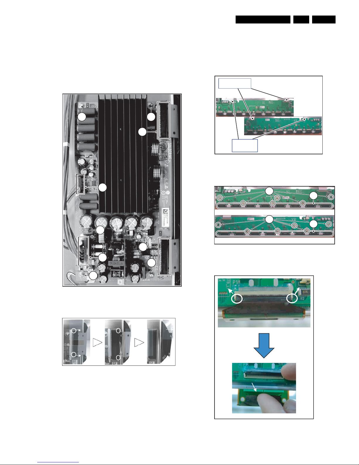
4.2.6 X-board
1. Unplug the power cable.
2. Unplug the signal cable.
3. Remove the heatsink.
4. Separate the TCP’s [1].
5. Remove the fixation screws [2].
Figure 4-13 X board removal 1/2
Figure 4-14 X board removal 2/2
Figure 4-15 TCP Separation
G_16390_033.eps
0108069
1
1
2
22
2
3
3
2
F_15590_052.eps
040705
Signal cables
G_16390_028.eps
010906
cables
Power
X Right board
G_16390_027.eps
220806
X Left board
2
1
1
2
G_16390_034.eps
100806
 Loading...