

Philips 27T500 Schematic

Philips Consumer Electronics
com
Philips Consumer Electronics
Philips Consumer ElectronicsPhilips Consumer Electronics
Technical Service Data
Service and Quality
Service Publications Dept.
One Philips Drive
P.O. Box 14810
Knoxville, TN 37914
Pg. SCHEMATIC DIAGRAMS AND PC BOARDS
Manual
Manual 7523
Manual Manual
Model no
Model no.:
Model noModel no
First Publish
First Publish:
First PublishFirst Publish
Rev
Rev.
. Date
Date:
RevRev
. .
DateDate
Print Date
Print Date:
Print DatePrint Date
7523
75237523
.: 27
27TTTT500
.: .:
: 10
: :
: 11
: :
500
2727
500500
: 11
11----26
: :
1111
10----1111----96
1010
11////26
26////2005
1111
2626
26----2005
2005
2626
20052005
96
9696
2005
20052005
1. MAIN CHASSIS SECTION 1
2. MAIN CHASSIS SECTION 2
3. MAIN CHASSIS SECTION 3
4. MAIN CHASSIS SECTION 4
5. MAIN CHASSIS SECTION 5
6. MAIN CHASSIS SECTION 6
7. MAIN CHASSIS SECTION 7
8. MAIN CHASSIS SECTION 8
9. IR RECEIVER ASSM
10. KEYBOARD MODULE - ASW113
11. CRT MODULE - APT133
12. RF TRANSMITTER MODULE - A10538
13. DIODE MODULATOR - AWR004
14. COLOR PIP MODULE - APP012
15. MAIN CHASSIS CBA (TOP)
16. MAIN CHASSIS CBA (BOTTOM)
17. CRT MODULE CBA - APT133
18. COLOR PIP MODULE CBA (TOP )
19. COLOR PIP MODULE CBA (BOTTOM )
REFER TO SAFETY GUIDELINES
REFER TO SAFETY GUIDELINES
REFER TO SAFETY GUIDELINESREFER TO SAFETY GUIDELINES
SAFETY NOTICE
SAFETY NOTICE:::: ANY PERSON ATTEMPTING TO SERVICE THIS CHASSIS MUST FAMILIARIZE
SAFETY NOTICESAFETY NOTICE
HIMSELF WITH THE CHASSIS AND BE AWARE OF THE NECESSARY SAFETY PRECAUTIONS
HIMSELF WITH THE CHASSIS AND BE AWARE OF THE NECESSARY SAFETY PRECAUTIONS
HIMSELF WITH THE CHASSIS AND BE AWARE OF THE NECESSARY SAFETY PRECAUTIONSHIMSELF WITH THE CHASSIS AND BE AWARE OF THE NECESSARY SAFETY PRECAUTIONS
TO BE USED WHEN SERVICING ELECTRONIC EQUIPMENT CONTAINING HIGH VOLTAGES
TO BE USED WHEN SERVICING ELECTRONIC EQUIPMENT CONTAINING HIGH VOLTAGES....
TO BE USED WHEN SERVICING ELECTRONIC EQUIPMENT CONTAINING HIGH VOLTAGESTO BE USED WHEN SERVICING ELECTRONIC EQUIPMENT CONTAINING HIGH VOLTAGES
CAUTION
CAUTION:
CAUTIONCAUTION
© Philips Electronics North America Corporation Visit our World Wide Web Site at http://www.forceonline.
: USE A SEPARATE ISOLATION TRANSFORMER FOR THIS UNIT WHEN SERVICING
USE A SEPARATE ISOLATION TRANSFORMER FOR THIS UNIT WHEN SERVICING
: :
USE A SEPARATE ISOLATION TRANSFORMER FOR THIS UNIT WHEN SERVICINGUSE A SEPARATE ISOLATION TRANSFORMER FOR THIS UNIT WHEN SERVICING
ANY PERSON ATTEMPTING TO SERVICE THIS CHASSIS MUST FAMILIARIZE
ANY PERSON ATTEMPTING TO SERVICE THIS CHASSIS MUST FAMILIARIZE ANY PERSON ATTEMPTING TO SERVICE THIS CHASSIS MUST FAMILIARIZE

Philips Consumer Electronics
com
Philips Consumer Electronics
Philips Consumer ElectronicsPhilips Consumer Electronics
Technical Service Data
Service and Quality
Service Publications Dept.
One Philips Drive
P.O. Box 14810
Knoxville, TN 37914
Manual
Manual 7523
Manual Manual
Model no
Model no.:
Model noModel no
First Publish
First Publish:
First PublishFirst Publish
Rev
Rev.
. Date
Date:
RevRev
. .
DateDate
Print Date
Print Date:
Print DatePrint Date
7523
75237523
.: 27
27TTTT500
.: .:
: 10
: :
: 11
: :
500
2727
500500
: 11
11----26
: :
1111
10----1111----96
1010
11////26
26////2005
1111
2626
26----2005
2005
2626
20052005
96
9696
2005
20052005
Safety Notes
Safety Notes
Safety NotesSafety Notes
REFER TO SAFETY GUIDELINES
REFER TO SAFETY GUIDELINES
REFER TO SAFETY GUIDELINESREFER TO SAFETY GUIDELINES
SAFETY NOTICE
SAFETY NOTICE:::: ANY PERSON ATTEMPTING TO SERVICE THIS CHASSIS MUST FAMILIARIZE
SAFETY NOTICESAFETY NOTICE
HIMSELF WITH THE CHASSIS AND BE AWARE OF THE NECESSARY SAFETY PRECAUTIONS
HIMSELF WITH THE CHASSIS AND BE AWARE OF THE NECESSARY SAFETY PRECAUTIONS
HIMSELF WITH THE CHASSIS AND BE AWARE OF THE NECESSARY SAFETY PRECAUTIONSHIMSELF WITH THE CHASSIS AND BE AWARE OF THE NECESSARY SAFETY PRECAUTIONS
TO BE USED WHEN SERVICING ELECTRONIC EQUIPMENT CONTAINING HIGH VOLTAGES
TO BE USED WHEN SERVICING ELECTRONIC EQUIPMENT CONTAINING HIGH VOLTAGES....
TO BE USED WHEN SERVICING ELECTRONIC EQUIPMENT CONTAINING HIGH VOLTAGESTO BE USED WHEN SERVICING ELECTRONIC EQUIPMENT CONTAINING HIGH VOLTAGES
CAUTION
CAUTION:
CAUTIONCAUTION
© Philips Electronics North America Corporation Visit our World Wide Web Site at http://www.forceonline.
: USE A SEPARATE ISOLATION TRANSFORMER FOR THIS UNIT WHEN SERVICING
USE A SEPARATE ISOLATION TRANSFORMER FOR THIS UNIT WHEN SERVICING
: :
USE A SEPARATE ISOLATION TRANSFORMER FOR THIS UNIT WHEN SERVICINGUSE A SEPARATE ISOLATION TRANSFORMER FOR THIS UNIT WHEN SERVICING
ANY PERSON ATTEMPTING TO SERVICE THIS CHASSIS MUST FAMILIARIZE
ANY PERSON ATTEMPTING TO SERVICE THIS CHASSIS MUST FAMILIARIZE ANY PERSON ATTEMPTING TO SERVICE THIS CHASSIS MUST FAMILIARIZE
GENERAL SAFETY NOTES
IMPORTANT SAFETY NOTICE
Proper service and repair is important to the safe, reliable operation of all Philips Consumer Electronics
Company** equipment. The service procedures recommended by Philips and described in this service
manual are effective methods of performing service operations. Some of these service operations require
the use of tools specially designed for the purpose. The special tools should be used when and as
recommended.
It is important to note that this manual contains various CAUTIONS and NOTICES which should be
carefully read in order to minimize the risk of personal injury to service personnel. The possibility exists
that improper service methods may damage the equipment. It also is important to understand that these
CAUTIONS and NOTICES ARE NOT EXHAUSTIVE. Philips could not possibly know, evaluate and
advise the service trade of all conceivable ways in which service might be done or of the possible
hazardous consequences of each way. Consequently, Philips has not undertaken any such broad
evaluation. Accordingly, a servicer who uses a service procedure or tool which is not recommended by
Philips must first satisfy himself thoroughly that neither his safety nor the safe operation of the equipment
will be jeopardized by the service method selected.
** Hereafter throughout this manual, Philips Consumer Electronics Company will be referred to as
Philips.
WARNING
Critical components having special safety characteristics are identified with a or
in the parts list and enclosed within a broken line* (where several critical components are grouped in one
area) along with the safety symbol on the schematics or exploded views. Use of substitute
replacement parts which do not have the same specified safety characteristics may create shock, fire, or
other hazards. Under no circumstances should the original design be modified or altered without written
permission from Philips. Philips assumes no liability, express or implied, arising out of any unauthorized
modification of design. Servicer assumes all liability.
• Broken Line ____ _ ____ _ ____ _ ____
"S"
by the Ref. No.
SAFETY CHECKS
After the original service problem has been corrected, a complete safety check should be made. Be sure
to check over the entire set, not just the areas where you have worked. Some previous servicer may
have left an unsafe condition, which could be unknowingly passed on to Your customer. Be sure to check
all of the following:
FIRE AND SHOCK HAZARD
IMPLOSION
X-RADIATION
LEAKAGE CURRENT COLD CHECK
LEAKAGE CURRENT HOT CHECK
PICTURE TUBE REPLACEMENT

PARTS REPLACEMENT
FIRE AND SHOCK HAZARD
1. Be sure all components are positioned in such a way as to avoid the possibility of adjacent component
shorts. This is especially important on those chassis which are transported to and from the service shop.
2. Never release a repaired unit unless all protective devices such as insulators, barriers, covers, strain
reliefs, and other hardware have been installed in accordance with the original design.
3. Soldering and wiring must be inspected to locate possible cold solder joints, solder splashes, sharp
solder points, frayed leads, pinched leads, or damaged insulation (including the ac cord). Be certain to
remove loose solder balls and all other loose foreign particles.
4. Check across-the-line components and other components for physical evidence of damage or
deterioration and replace if necessary. Follow original layout, lead length, and dress.
5. No lead or component should touch a receiving tube or a resistor rated at 1 watt or more. Lead
tension around protruding metal surfaces or edges must be avoided.
6. Critical components having special safety characteristics are identified with an 'S' by the Ref. No. in
the parts list and enclosed within a broken line* (where several critical components are grouped in one
area) along with the safety symbol on the schematic diagrams and /or exploded views.
7. When servicing any unit, always use a separate isolation transformer for the chassis. Failure to use a
separate isolation transformer may expose you to possible shock hazard, and may cause damage to
servicing instruments.
8. Many electronic products use a polarized ac line cord (one wide pin on the plug). Defeating this
safety feature may create a potential hazard to the servicer and the user. Extension cords which do not
incorporate the polarizing feature should never be used.
9. After reassembly of the unit, always perform an
to all exposed metal parts of the cabinet. Also, check all metal control shafts (with knobs removed),
antenna terminals, handles, screws, etc., to be sure the unit may be safely operated without danger of
electrical shock.
* Broken line ____ _ ____ _ ____ _ ____
ac leakage test
or resistance test from the line cord
IMPLOSION
1. All picture tubes used in current model receivers are equipped with an integral implosion system.
Care should always be used, and safety glasses worn, whenever handling any picture tube. Avoid
scratching or otherwise damaging the picture tube during installation.
2. Use only replacement tubes specified by the manufacturer.
X-RADIATION

1. Be sure procedures and instructions to all your service personnel cover the subject of X-radiation.
jumper from the ac line cord.
Potential sources of X-rays in TV receivers are the picture tube and the high voltage circuits. The basic
precaution which must be exercised is to keep the high voltage at the factory recommended level.
2. To avoid possible exposure to X-radiation and electrical shock, only the manufacturer's specified
anode connectors must be used.
3. It is essential that the service technician has an accurate HV meter available at all times. The
calibration of this meter should be checked periodically against a reference standard.
4. When the HV circuitry is operating properly there is no possibility of an X-radiation problem. High
voltage should always be kept at the manufacturer's rated value - no higher - for optimum performance.
Every time a color set is serviced, the brightness should be run up and down while monitoring the HV
with a meter to be certain that the HV is regulated correctly and does not exceed the specified value. We
suggest that you and your technicians review test procedures so that HV and HV regulation are always
checked as a standard servicing procedure, and the reason for this prudent routine is clearly understood
by everyone. It is important to use an accurate and reliable HV meter. It is recommended that the HV
reading be recorded on each customer's invoice, which will demonstrate a proper concern for the
customer's safety.
5. When troubleshooting and making test measurements in a receiver with a problem of excessive high
voltage, reduce the line voltage by means of a Variac to bring the HV into acceptable limits while
troubleshooting. Do not operate the chassis longer than necessary to locate the cause of the excessive
HV.
6. New picture tubes are specifically designed to withstand higher operating voltages without creating
undesirable X-radiation. It is strongly recommended that any shop test fixture which is to be used with
the new higher voltage chassis be equipped with one of the new type tubes designed for this service.
Addition of a permanently connected HV meter to the shop test fixture is advisable. The CRT types used
in these new sets should never be replaced with any other types, as this may result in excessive
X-radiation.
7. It is essential to use the specified picture tube to avoid a possible X-radiation problem.
8. Most TV receivers contain some type of emergency "Hold Down" circuit to prevent HV from rising to
excessive levels in the presence of a failure mode. These various circuits should be understood by all
technicians servicing them, especially since many hold down circuits are inoperative as long as the
receiver performs normally.
LEAKAGE CURRENT COLD CHECK
1. Unplug the ac line cord and connect a jumper between the two prongs of the plug.
2. Turn on the power switch.
3. Measure the resistance value between the jumpered ac plug and all exposed cabinet parts of the
receiver, such as screw heads, antennas, and control shafts. When the exposed metallic part has a
return path to the chassis, the reading should be between 1 megohm and 5.2 megohms. When the
exposed metal does not have a return path to the chassis, the reading must be infinity. Remove the

LEAKAGE CURRENT HOT CHECK
1. Do not use an isolation transformer for this test. Plug the completely reassembled receiver directly
into the ac outlet.
2. Connect a
metallic cabinet part and a
3. Use an ac voltmeter with at least 5000 ohms/volt sensitivity to measure the potential across the
resistor.
4.
The potential at any point should not exceed 0.75 volts.
used to make this test; leakage current must not exceed 0.5milliamp. If a measurement is outside of the
specified limits, there is a possibility of shock hazard. The receiver should be repaired and rechecked
before returning it to the customer.
5
. Repeat the above procedure with the ac plug reversed.
necessary when a polarized plug is used. Do not defeat the polarizing feature of the plug.)
1.5k, 1OW resistor
good earth ground
paralleled by a
such as a water pipe, as shown below.
0.15uF. capacitor
A leakage current tester may be
between each exposed
(Note: An ac adapter is
OR
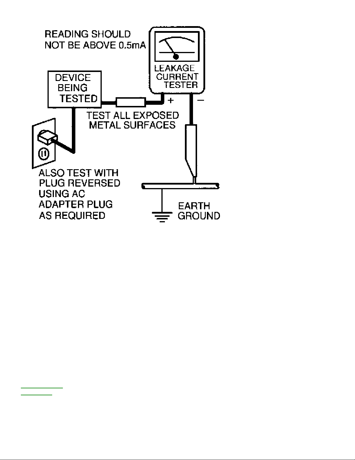
With the instrument completely reassembled, plug the AC line cord directly into a 120V AC outlet.
not use an isolation transformer during this test.)
metering system that complies with American National Standards Institute (ANSI) C101.1 Leakage
Current for Appliances and Underwriters Laboratories (UL) 1410, (50.7).
Use a leakage current tester or a
With the instrument
AC switch first in the on position and then in the off position, measure from a
known earth ground (metal water pipe, conduit, etc.) to all exposed metal
parts of the instrument (antennas, handle brackets, metal cabinet, screw
heads, metallic overlays, control shafts, etc.), especially any exposed metal
parts that offer an electrical return path to the chassis. Any current
measured must not exceed 0.5 milliamp. Reverse the instrument power cord
plug in the outlet and repeat the test. See graphic below.
(Do
The primary source of X-radiation in this television receiver is the picture tube. The picture tube utilized
These characteristics are often not evident from visual inspection nor can the protection afforded by them
PICTURE TUBE REPLACEMENT
in this chassis is specially constructed to limit X-radiation emissions. For continued X-radiation protection,
the replacement tube must be the same type as the original, including suffix letter, or a Philips approved
type.
PARTS REPLACEMENT
Many electrical and mechanical parts in Philips television sets have special safety related characteristics.
necessarily be obtained by using replacement components rated for higher voltage, wattage, etc. The
use of a substitute part which does not have the same safety characteristics as the Philips recommended
replacement part shown in this service manual may create shock, fire, or other hazards
TV SAFETY NOTES
SAFETY CHECKS
IMPLOSION

X-RADIATION
PICTURE TUBE REPLACEMENT
PARTS REPLACEMENT
WARNING
Before removing the CRT anode cap, turn the unit OFF and short the HIGH VOLTAGE to the CRT DAG
ground.
SERVICE NOTE:
The CRT DAG is not at chassis ground.
TV-VCR COMBI SAFETY NOTES
IMPORTANT SAFETY PRECAUTIONS
Prior to shipment from the factory, our products are strictly inspected for recognized product safety and
electrical codes of the countries in which they are to be sold. However, in order to maintain such
compliance, it is equally important to implement the following precautions when a set is being serviced.
SAFETY PRECAUTIONS FOR TV CIRCUITS
1. Before returning an instrument to the customer, always make a safety check of the entire instrument,
including, but not limited to, the following items:
a. Be sure that no built-in protective devices are defective or have been defeated during servicing. (1)
Protective shields are provided on this chassis to protect both the technician and the customer.
Correctly replace all missing protective shields, including any removed for servicing convenience. (2)
When reinstalling the chassis and/or other assembly in the cabinet, be sure to put back in place all
protective devices, including but not limited to, nonmetallic control knobs, insulating fishpapers,
adjustment and compartment covers/shields, and isolation resistor/capacitor networks. Do not
operate this instrument or permit it to be operated without all protective devices correctly installed and
functioning. Servicers who defeat safety features or fail to perform safety checks may be liable for any
resulting damage.
b. Be sure that there are no cabinet openings through which an adult or child might be able to insert
their fingers and contact a hazardous voltage. Such openings include, but are not limited to, (1)
spacing between the picture tube and the cabinet mask, (2) excessively wide cabinet ventilation slots,
and (3) an improperly fitted and/or incorrectly secured cabinet back cover.
c. Do a
ANY MEASUREMENTS NOT WITHIN THE LIMITS SPECIFIED HEREIN INDICATE A POTENTIAL SHOCK
HAZARD THAT MUST BE ELIMINATED BEFORE RETURNING THE INSTRUMENT TO THE CUSTOMER OR
BEFORE CONNECTING THE ANTENNA OR ACCESSORIES.
LEAKAGE CURRENT CHECK

d. X-Radiation and High Voltage Limits - Because the picture tube is the primary potential source
of X-radiation in solid-state TV receivers, it is specially constructed to prohibit X-radiation emissions.
For continued X-radiation protection, the replacement picture tube must be the same type as the
original. Also, because the picture tube shields and mounting hardware perform an X-radiation
protection function, they must be correctly in place. High voltage must be measured each time
servicing is performed that involves B+, horizontal deflection or high voltage. Correct operation of the
X-radiation protection circuits also must be reconfirmed each time they are serviced. (X-radiation
protection circuits also may be called "horizontal disable" or "hold down.") Read and apply the high
voltage limits and, if the chassis is so equipped, the X-radiation protection circuit specifications given
on instrument labels and in the Product Safety & X-Radiation Warning note on the service data
chassis schematic. High voltage is maintained within specified limits by close tolerance safety-related
components/adjustments in the high-voltage circuit. If high voltage exceeds specified limits, check
each component specified on the chassis schematic and take corrective action.
2. Read and comply with all caution and safety-related notes on or inside the receiver cabinet, on the
receiver chassis, or on the picture tube.
3. Design Alteration Warning - Do not alter or add to the mechanical or electrical design of this TV
receiver. Design alterations and additions, including, but not limited to circuit modifications and the
addition of items such as auxiliary audio and/or video output connections, might alter the safety
characteristics of this receiver and create a hazard to the user. Any design alterations or additions will
void the manufacturer's warranty and may make you, the servicer, responsible for personal injury or
property damage resulting therefrom.
4. Picture Tube Implosion Protection Warning - The picture tube in this receiver employs integral
implosion protection. For continued implosion protection, replace the picture tube only with one of the
same type number. Do not remove, install, or otherwise handle the picture tube in any manner without
first putting on shatterproof goggles equipped with side shields. People not so equipped must be kept
safely away while picture tubes are handled. Keep the picture tube away from your body. Do not handle
the picture tube by its neck. Some "in-line" picture tubes are equipped with a permanently attached
deflection yoke; because of potential hazard, do not try to remove such "permanently attached" yokes
from the picture tube.
5. Hot Chassis Warning
a. Some TV receiver chassis are electrically connected directly to one conductor of the ac power cord
and may be serviced safely without an isolation transformer only if the ac power plug is inserted so
that the chassis is connected to the ground side of the ac power source. To confirm that the ac
power plug is inserted correctly, with an ac voltmeter, measure between the chassis and a known
earth ground. If a voltage reading in excess of 1.OV is obtained, remove and reinsert the ac power
plug in the opposite polarity and again measure the voltage potential between the chassis and a
known earth ground.
b. Some TV receiver chassis normally have 85Vac (RMS) between chassis and earth ground
regardless of the ac plug polarity. This chassis can be safety-serviced only with an isolation
transformer inserted in the power line between the receiver and the ac power source, for both
personnel and test equipment protection. Some TV receiver chassis have a secondary ground system
in addition to the main chassis ground. This secondary ground system is not isolated from the ac
power line. The two ground systems are electrically separated by insulation material that must not
be defeated or altered.
6. Observe original lead dress. Take extra care to assure correct lead dress in the following areas: a.
near sharp edges, b. near thermally hot parts - be sure that leads and components do not touch

thermally hot parts, c. the ac supply, d. high voltage, and e. antenna wiring. Always inspect in all areas
for pinched, out of place, or frayed wiring. Check ac power cord for damage.
7. Components, parts, and/or wiring that appear to have overheated or are otherwise damaged should be
replaced with components, parts, or wiring that meet original specifications. Additionally, determine the
cause of overheating and/or damage and, if necessary, take corrective action to remove any potential
safety hazard.
PRECAUTIONS DURING SERVICE
A. Parts identified by the symbol are critical for safety. Replace only with part number specified.
B. In addition to safety, other parts and assemblies are specified for conformance with regulations
applying to spurious radiation. These must also be replaced only with specified replacements.
Examples:
C. Use specified internal wiring. Note especially:
1) Wires covered with PVC tubing
2) Double insulated wires
3) High voltage leads
D. Use specified insulating materials for hazardous
live parts. Note especially:
1) Insulation Tape
2) PVC tubing
3) Spacers
4) Insulators for transistors
RF converters, RF cables, noise blocking capacitors, and noise blocking filters, etc.
E. When replacing ac primary side components (transformers, power cord, etc.), wrap ends of wires
securely about the terminals before soldering.
F. Observe that the wires do not contact heat producing parts (heatsinks, oxide metal film resistors,
fusible resistors, etc.)
G. Check that replaced wires do not contact sharp edged or pointed parts.
H. When a power cord has been replaced, check that 10-15 kg of force in any direction will not
loosen it.
I. Also check areas surrounding repaired locations.
J. Use care that foreign objects (screws, solder droplets, etc.) do not remain inside the set.
K. Crimp type wire connector
When replacing the power transformer in sets where the connections between the power cord and power
transformer primary lead wires are performed using crimp type connectors, in order to prevent shock
hazards, perform carefully and precisely the following steps.
Replacement procedure
1) Remove the old connector by cutting the wires at a point close to the connector. Important: Do
not re-use a connector (discard it).
2) Strip about 15 mm of the insulation from the ends of the wires. If the wires are stranded, twist
the strands to avoid frayed conductors.
3) Align the lengths of the wires to be connected. Insert the wires fully into the connector.
4) Use the crimping tool to crimp the metal sleeve at the center position. Be sure to crimp fully to
the complete closure of the tool.
L. When connecting or disconnecting the VCR connectors, first, disconnect the ac plug from the ac supply
socket.
SAFETY CHECK AFTER SERVICING
Examine the area surrounding the repaired location for damage or deterioration. Observe that screws,
parts and wires have been returned to original positions. Afterwards, perform the following tests and
confirm the specified values in order to verify compliance with safety standards.
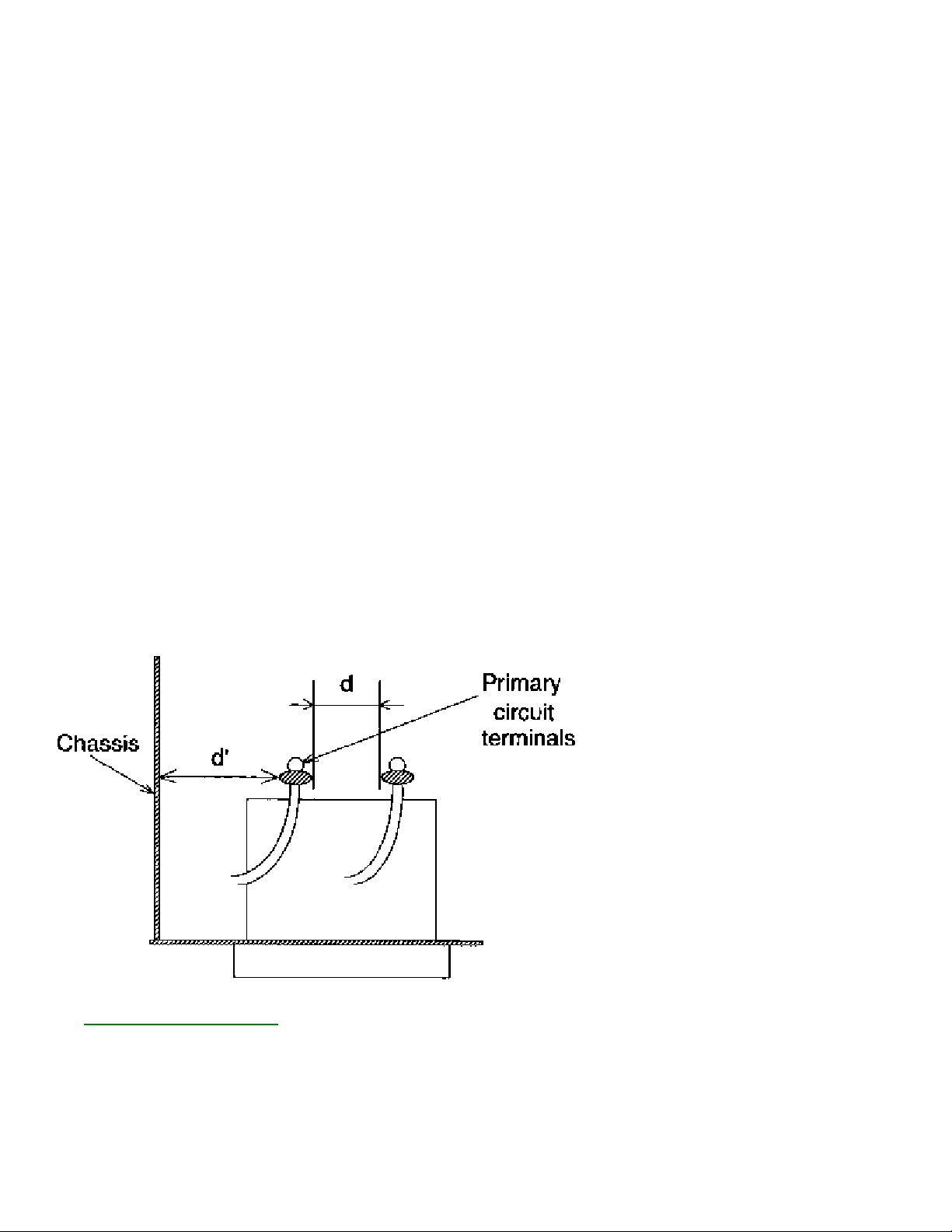
1. Clearance Distance
When replacing primary circuit components, confirm specified clearance distance (d) and (d') between
soldered terminals, and between terminals and surrounding metallic parts. (See graphic bllow)
Table 1 : Ratings for selected area
AC Line Voltage Region Clearance Distance
(d) (d')
USA or > 3.2 mm
110 to 130 V CANADA (0.126 inches)
Note: This table is unofficial and for reference only. Be sure to confirm the precise values.
2.
LEAKAGE CURRENT CHECKS

VCR SAFETY NOTES
This device employs many circuits, components, and mechanical parts designed for protection against
FIRE & SHOCK HAZARD (VCR)
1. Be sure that all components are positioned in such a way to avoid possibility of shorts to adjacent
components. This is especially important on those chassis which are transported to and from the repair
shop.
2. Always replace all protective devices such as insulators and barriers after working on a set.
3. Check for damaged insulation on wires including the ac cord.
4. Check across-the-line components for damage and replace if necessary.
5. After re-assembly of the unit, always perform an ac leakage test on the exposed metallic parts of the
cabinet such as the knobs, antenna terminals, etc. to be sure the set is safe to operate without danger of
electrical shock. Do not use a line isolation transformer during this test. Use an ac voltmeter
having 5000 ohms per volt or more sensitivity in the following manner: Connect a 1500 ohm 10 wan
resistor, paralleled by 0.15 MFD ac type capacitor, between a known good earth ground (water pipe,
conduit, etc.) and the exposed metallic parts, one at a time. Measure the ac voltage across the
combination 1500 ohm resistor and 0.15 MFD capacitor. Reverse the ac plug on the set and repeat ac
voltage measurements again for each exposed metallic part. Voltage measured must not exceed O.6 volts
R.M.S. This corresponds to 0.4 milliamp ac. Any value exceeding this limit constitutes a potential shock
hazard and must be corrected immediately.
GENERAL
Power Supply-This receiver is designed for operation on 120 Volts, 6OHz alternating current (ac) only.
Never connect to a supply having a different frequency or voltage.
IMPORTANT NOTICE
fire, shock and RF interference. For continued safety any servicing should be performed by qualified
personnel and exact replacement parts should be used. Under no circumstances should the original
design be altered.
PRODUCT SAFETY GUIDELINES FOR ALL PRODUCTS
CAUTION
familiar with all of the following safety checks. Risk of potential hazards and injury to the user increases if
safety checks are not adhered to.
USE A SEPARATE ISOLATION TRANSFORMER FOR THIS UNIT WHEN SERVICING.
: Do not modify any circuit. Service work should be performed only after you are thoroughly

PREVENTION OF ELECTROSTATIC DISCHARGE (ESD)
This reminder is provided to call the CATV system installer's attention to article 820-22 of the NEC that
Some semiconductor solid state devices can be damaged easily by static electricity. Such components
commonly are called Electrostatically Sensitive (ES) Devices, Examples of typical ES devices are
integrated circuits and some field-effect transistors and semiconductor "chip" components. The following
techniques should be used to help reduce the incidence of component damage caused by electrostatic
discharge (ESD).
1. Immediately before handling any semiconductor component or semiconductor-equipped assembly,
drain off any ESD on your body by touching a known earth ground. Alternatively, obtain and wear a
commercially available discharging ESD wrist strap, which should be removed for potential shock reasons
prior to applying power to the unit under test.
2. After removing an electrical assembly equipped with ES devices, place the assembly on a conductive
surface such as aluminum foil, to prevent electrostatic charge buildup or exposure of the assembly.
3. Use only a grounded-tip soldering iron to solder or unsolder ES devices.
4. Use only an anti-static solder removal device. Some solder removal devices not classified as "antistatic
(ESD protected)" can generate an electrical charge sufficient to damage ES devices.
5. Do not use freon·propelled chemicals. These can generate electrical charges sufficient to damage ES
devices.
6. Do not remove a replacement ES device from its protective package until immediately before you are
ready to install it (Most replacement ES devices are packaged with leads electrically shorted together by
conductive foam, aluminum foil or comparable conductive material).
7. Immediately before removing the protective material from the leads of a replacement ES device, touch
the protective material to the chassis or circuit assembly into which the device will be installed.
CAUTION : Be sure no power is applied to the chassis or circuit and observe all other safety precautions.
8. Minimize bodily motions when handling unpackaged replacement ES devices. (Otherwise harmless
motion such as the brushing together of your clothes fabric or the lifting of your feet from a carpeted
floor can generate static electricity (ESD) sufficient to damage an ES device.)
NOTE to CATV system Installer:
provides guidelines for proper grounding and, in particular, specifies that the cable ground shall be
connected to the grounding system of the building, as close to the point of cable entry as practical.
 Loading...