

Philips 26MF605, 32MF605 Schematic
FL-1 Wide LCD Monitor / TV
Service
Service
Service
FL-1-26 FL-1-32
26MF605W/17
32
MF605W/17
""
Horizontal frequencies
30-50kHz
TABLE OF CONTENTS
Description Page
Important Safety Notice---- ------------------------------ 2
Technical Data-------------------------------------------3~4
Instalation/On Screen Display------------------------5~7
Troubleshooting--------------------------------------------8
Lock/unlock,Aging,Factory mode-----------------------9
Circuit Description-----------------------------------10~11
Mechanical Instructions----------------------------12~13
Definition of pixel defects -------------------------------14
Warning Message ----------------------------------------15
Electrical instruction --------------------------------16~20
DDC Instructions-------------------------------------21~27
Failure mode of panel------------------------------------28
Safety Test Requirments--------------------------------29
ISP Instructions --------------------------------------30~32
Repair tips---------------------------------------------33~34
SAFETY NOTICE
ANY PERSON ATTEMPTING TO SERVICE THIS CHASSIS MUST FAMILIARIZE HIMSELF WITH THE CHASSIS
AND BE AWARE OF THE NECESSARY SAFETY PRECAUTIONS TO BE USED WHEN SERVICING ELECTRONIC
EQUIPMENT CONTAINING HIGH VOLTAGES.
Description Page
Color adjustment------------------------------------35~36
Repair Flow chart-----------------------------------37~38
Block Diagram---------------------------------------39~40
Wiring Diagram------------------------------------------41
Scaler Diagram&C.B.A. ---------------------------42~58
Power Diagram & C.B.A. --------------------------59~62
HD Diagram & C.B.A. ------------------------------63~65
IR Diagram & C.B.A. -------------------------------66~68
Key Diagram & C.B.A. -----------------------------69~70
Side AV Diagram & C.B.A. ------------------------71~73
Exploded View------------------------------------------- 74
Spare/recommended parts list ------------------75~79
General product specification--------------------80~97
DDC DATA------------------------------------------98~103
Different parts list--------------------------------------104
CAUTION: USE A SEPARATE ISOLATION TRANSFORMER FOR THIS UNIT WHEN SERVICING.
REFER TO BACK COVER FOR IMPORTANT SAFETY GUIDELINES
Published by BCU Monitors Printed in Suzhou Copyright reserved Subject to modification K Feb. 01 2005
GB
3138 106 10446

2
26MF605W/17
Important Safety Notice
Go to cover page
Proper service and repair isimportant to the safe, reliable
operation of all HPConsumer Electronics Company**
Equipment. The service procedures recommended by HP and
described in this service manual are effective methods of
performing service operations. Some ofthese service
operations require the use of tools specially designed for the
purpose. The special tools should be used when and as
recommended.
It is important to note that this manual contains various
CAUTIONS and NOTICES which should be carefully read in
order to minimize the risk of personal injury to service
personnel. The possibility exists that improper service
methods may damage the equipment. It is also important to
understand that these CAUTIONS and NOTICES ARE NOT
EXHAUSTIVE. HP could not possibly know, evaluate and
advise the service trade of all conceivable ways in which
service might be done or of the possible hazardous
consequences of each way. Consequently, HP has not
undertaken any such broad evaluation. Accordingly, a
servicer who uses a service procedure or tool which is not
recommended by HP must first satisfy himself thoroughly that
neither his safety nor the safe operation of the equipment will
be jeopardized by the service method selected.
* * Hereafter throughout this manual, HP Consumer
Electronics Company will bereferred to as HP.
WARNING
Critical components having special safety characteristics are
identified with a bythe Ref. No. inthe parts list and
enclosed within a broken line*
(where several critical components are grouped in one area)
along with the safety symbol on the schematics or
exploded views.
Use of substitute replacement parts which do not have the
same specified safety characteristics may create shock, fire,
or other hazards.
Under no circumstances should the original design be
modified or altered without written permission from Philips.
Philips assumes no liability, express or implied, arising out of
any unauthorized modification of design.
Servicer assumes all liability.
*BrokenLine
FOR PRODUCTS CONTAINING LASER :
DANGER- Invisible laser radiation when open.
AVOID DIRECT EXPOSURE TO BEAM.
CAUTION- Use of controls or adjustments or
performance of procedures other than
those specified herein may result in
hazardous radiation exposure.
CAUTION- The use of optical instruments with this
product will increase eye hazard.
TO ENSURE THE CONTINUED RELIABILITY OF THIS
PRODUCT, USE ONLY ORIGINAL MANUFACTURER'S
REPLACEMENT PARTS, WHICH ARE LISTED WITH THEIR PART
NUMBERS IN THE PARTS LIST SECTION OF THIS
SERVICE MANUAL.
Take care during handling the LCD module with backlight
unit
- Must mount the moduleusing mounting holes arranged infour
corners.
- Do not press onthe panel, edge of theframe strongly or electric
shock as this will result in damage to the screen.
- Do not scratch orpress on the panel withany sharp objects, such
as pencil or pen asthis may result in damage to the panel.
- Protect the module fromthe ESD as it maydamage the electronic
circuit (C-MOS).
- Make certain that treatment person s body are grounded through
wrist band.
- Do not leave themodule in high temperature andin areas of high
humidity for a long time.
- Avoid contact with water as it may ashort circuit within the module.
- If the surface ofpanel become dirty, please wipe it off with a soft
material. (Cleaning with a dirty or rough cloth may damage the
panel.)
Technical Data
26MF605W/17
Go to cover page
3
LCD panel
Type NR. : )
Out dimensions : 626.0(H) x 373.0(V) x 44.1(D) mm (Typ.)
line
Pitch (mm) : 0.4215(H) x 0. (V)
Pixel format : 1 hori. By 7 vert. pixels
Color pixel arrangement: RGB vertical stripe
Display surface : Anti-glare
Number of color : ( bits)
Backlight : FL
Active area (WxH) :
View angle
Contrast ratio : Typical : 1
uminance : ( )
L of white 500 cd/m Center 1 points, Typ.
AC-input : 90V ~ 264V
Power consumption : W
Power cord length : 1.8M
Power cord type : 3 lead with earth plug , plugable (US type)
Power indicator : LED (On: Green ,Sleeping mode: Amber )
Auto power saving : EPA, Nutek, VESADPMS
Horizontal scan : 30 KHz
Vertical scan : 56 Hz
Display mode : Multi-modes
Horizontal scanning
Vertical scanning
White balance Adjustment
Note: Use Minolta CA-110 for color coordinates and luminance check.
Normal X (center) = 0.289 ± 0.030
(8500 ° K CIE Coordinates) Y (center) = 0.304 ± 0.030
LC260WX2 (Supplier LPL
366 68
Hard coating(3H), treatment
of the front polarizer
16,777,216 colors 8
18 EE
575.769mm x 323.712mm
: Viewing angle free(R/L 176(Typ.),
U/D 176(Typ.))
70 /Typ(at PC mode),105W/Typ(at TV
mode).
~50
~63
Sync polarity : Positive or negative
Scanning frequency : 30 ~ 50 KHz
Sync polarity : Positive or negative
Scanning frequency : 56 ~ 63 Hz
4215
600
2
AC,50/602Hz
Pin No. Description
1RX22RX2+
3GND
4GND
5GND
6 DDC clock
7 DDC data
8GND
9RX110 RX1+
11 GND
12 GND
13 GND
14 +5V
15 DVI-D self test
16 +5V
17 RX018 RX0+
19 GND
20 GND
21 GND
22 GND
23 RXC+
24 RXC-
Environmental conditions
Operating
- Temperature : 0 to 40
- Humidity : 10 to 95%(non - condensing)
- Altitude : 0 to 12000 feet
- Air pressure : 600 to 1100 mBAR
- (guaranteed optical performance) : 5 to 35
- (guaranteed functional performance) : 5 to 40
Storage
- Temperature : -20 to 50
- Humidity : 10 to 95% (non - condensing )
- Air pressure : 600 to 1100 mBAR
Note:recommendat0to35°C, Humidity less than 60 %
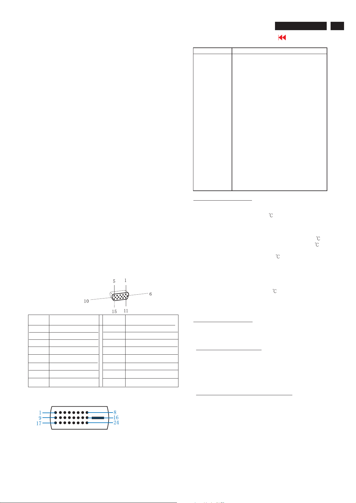
Pin Assignment
Pin No.
2
3
4
5
6
7
8
Input DVI-D connector pin
Assignment
Red video input
1
Green video input
Blue video input
GND
Cable detect
Red video GND
Green video GND
Blue video GND
Pin No.
9
10
11
12
13
14
15
Assignment
DDC +3.3V OR +5V
GND
GND
Serial data line (SDA)
H-sync
V-sync
Data clock line (SCL)
Shipping
- Temperature :( -20 to 50
- Humidity : 10 to 95% (non - condensing )
- Altitude : 0 to 40000 feet ( non operating )
- Air pressure : 600 to 1100
Marking and identification
In accordance with UAN-D1109 and the approval marking required by
the countries of destination.
Safety and EMI requirements
Safety requirement: CSA C22.2 NO.950-95, UL1950, UL, CSA, NOM
Ergonomic Requirement: TUV/GS, TUV/ERG, ISO13406-2 And the
relevant national safety standards.
EMI requirement : FCC Part 15 Class B, ICES-003
Power Management: EPA
Electri cal c haracter istics and perfor mance
Test signal and test method in accordance with test instructions sheet
161 of the product where applicable.
Input signals
a. Analog Video : 15 pin D-Sub 0.7 Vp-p linear, positive
polarity and separate Sync ( TTL level,
positive or negative polarity )
b. Audio signal : Mini-jack audio input
c. Signal source : Pattern generator format as attachment (
Timing table 1 to 6 )
d. Reference generator : CHROMA 2135 or 2250
)
4
26MF605W/17
Technical Data(Continued)
Go to cover page
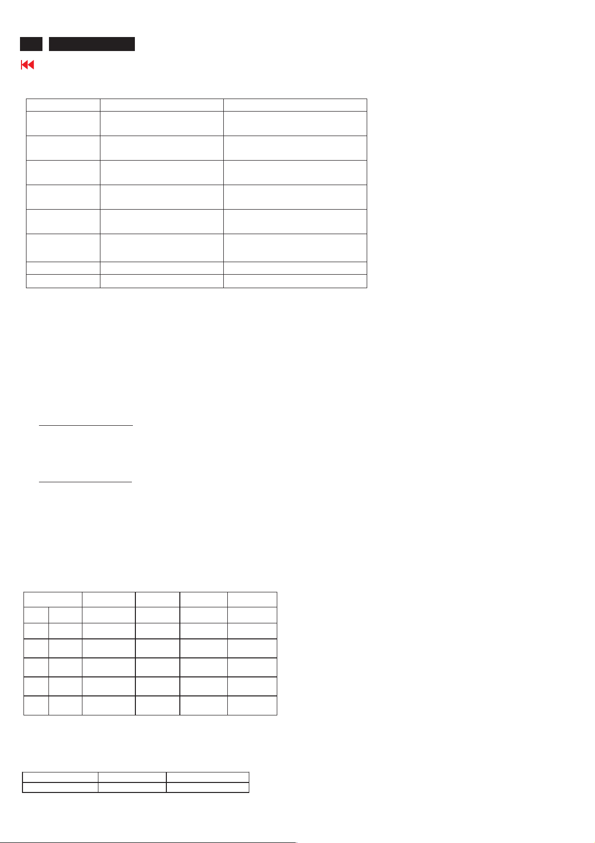
TV Signal type :
Signal type Video signal Audio signal
Video1/Video2/
Video3
S-Video1/
S_Video2
Component InputRCA Jack, Y, Pb , Pr,
PVR Output (CVBS include Tuner)
DVI IN Digital TV signal support
HD IN Input RCA Jack, Y, Pb, Pr
RF IN Aerial Input
Headphone Output 3.5mm stereo jack
Front/Top control panel definition:
Power SW : Power switch.
Power LED : Normal operationàGreen.
+Up/Down- : Channel up and down, and OSD cursor up and down.
-Left/Right+ : Volume up and down, and OSD cursor left and right
Menu : Enable and EXIT OSD menu(enter key for PC).
IR receiver : Sense the signal from RC handset.
Input RCA Jack, Yellow Share with S-Video or Component
RCA Jack , White / Red
Input S-terminal, Black Share with Video1/Video2
RCA Jack, white / Red
Share with Video3
Green, Blue, Red
RCA Jack , Yellow
HDCP DVI connector
Green, Blue, Red
Sleeping modeàAmber.
RCA Jack, white / Red
Output (CVBS audio)
RCA Jack, white / Red
Input, L/R RCA Jack,
white / Red
Input, L/R RCA Jack,
white / Red
Remote control unit definition
Function Keys
The remote control is used in all PC and TV modes:
At PC mode function keys:
1. Press MENU Key to call Monitor Menu
2. Press Up/Down/Left/Right Key to select Monitor function
3. Left/Right is Volume Hot Key.
4. Use remote controller to control all PC menu function.
At TV mode function keys:
1. Press MENU Key to display TV Menu
2. Press Up/Down/Left/Right Key to select TV function
3. Up/Down Key is Channel Hot Key.
4. Left/Right Key is Volume Hot Key.
5. Use remote controller to control all TV menu function.
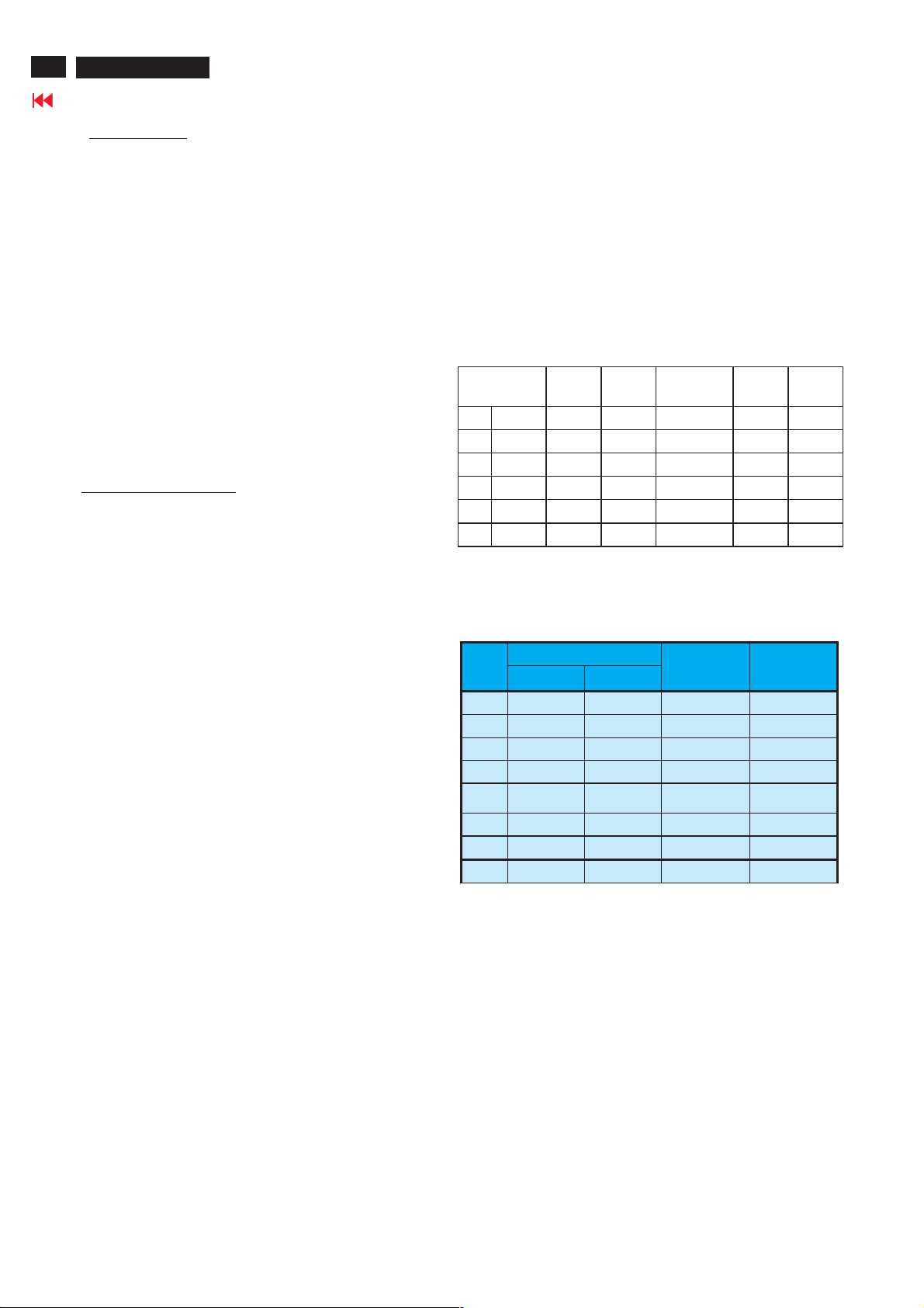
Display (for preset mode only)
Actual display size: 575.769mm X 323.712mm
Resolution
Factory Preset modes (6 modes)
Dot rate (MHz) H.freq (KHz) Mode Resolution V.freq (Hz)
25.175 31.469 IBM VGA 640 * 480 59.94
36 35.156 VESA 800 * 600 56.25
40.00 37.879 VESA 800 * 600 60.316
65.00 48.363 VESA 1024 * 768 60.004
CVT 74.5 47.772 WXGA 1280 * 720 59.855
CVT 79.5 47.776 WXGA 1280 * 768 59.87
Brightness output (Video signal 0.7V ± 2%)
Apply a 1280X768@60Hz signal with full white pattern, the center of
screen at original color brightness light output is
Brightness control Contrast control Light output Unit: nit
100% 100%
> 400
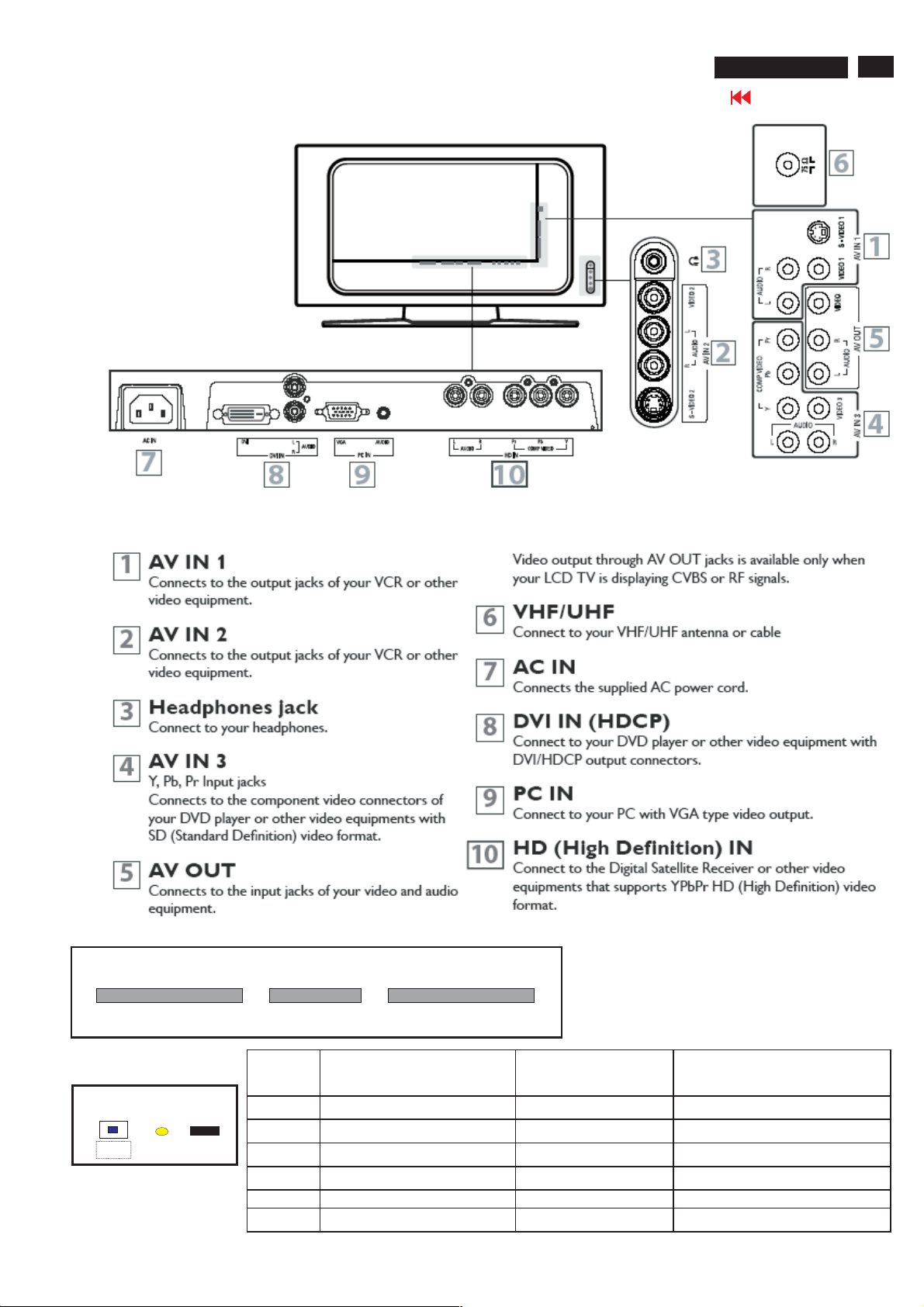
Installation
26MF605W/17
Go to cover page
5
Top Control
-
Volume
<B> <C> <D> <E> <F>
Front Control
Power SW
<A>
LED
RC sensor
+
RightLeft
Menu
-
Channel
Key Function VGA mode TV/video mode
<A> Power DC Power DC Power
<B> Left Left/Volume down Left/Volume down
<C> Right Right/Volume up Right/Volume up
<D> Menu Enter /Exit OSD menu Enter /Exit OSD menu
<E> Menu Down/channel down Menu line Down Menu Down/Channel Down
<F> Menu Up/Channel up Menu line Up Menu Up/Channel up
+
UpDown

6
26MF605W/17
Go to cover page
Installation

OSD Menu list
PC Signal control via front keyboard:
On Screen Display
TV Signal control via front keyboard :
Picture
Smart picture : Personal/Movie/Sport/weak signal/multimedia/
Brightness : Adjust brightness
Color : Adjust color saturation
Contrast : Adjust contrast.
Sharpness : Adjust sharpness
Tint : Adjust skin color
Audio
Smart sound : Personal/News/Music/Theatre
Setting : Treble/base/balance adjustment
Stereo : Stereo/mono select
Virtual surround: Virtual surround on/off
AVL : Auto volume limit on/off
Night
26MF605W/17
Go to cover page
7
Picture
Smart picture :Normal, warm, cool
Brightness :Adjust backlight
Contrast : Adjust contrast.
Auto adjust : Yes/no for PC auto alignment.
Manual adjust : Phase/clock/Horizontal/vertical
Audio
Smart sound : Personal/News/Music/Theatre
Setting : Treble/base/balance adjustment
Stereo : Stereo/mono select
Virtual surround: Virtual surround on/off
AVL : Auto volume limit on/off
Featu re
PIP : Size (small/medium/large/PBP);
Video (TVàVideo1àVideo2àVideo3à
S-Video1à S-Video2àComponentàTV )
Audio (PIP/PC)
Display (to change PIP display position)
Source : PCàDVIàTVàVideo1àVideo2àVideo3à
S-Video1àS-Video2àComponentàHDà PC
Install
Language : English/ Espanol / Francias
Factory reset : Recall Contrast, Brightness.
Feature
Source : TV/Video1 / Video2 / Video3 / S-Video1/
S-Video2/Component/HD/PC/DVI/TV.
Picture format : WIDESCREEN / 4:3/ ZOOM 16:9 / SUPER
WIDE /
Auto lock : Lock program/change code/clear all/block
option/movie rating/TV rating.
Close caption : caption mode (CC1;CC2;CC3;CC4;TXT1;TXT2;
TXT3;TXT4;CC mute)
CC display (CC on/off)
Color Temp : Normal/warm/cool
Ins tall
Language : English/ Espanol / Francias
Tuner mode : Antenna/cable/auto.
Auto program: Start
Channel edit : Channel(select channel)/Skipped(skip/
active).
Factory reset : Yes

8
26MF605W/17
Troubleshooting
Go to cover page
No Power
1. Check the TV power cord. Disconnect the power cord from the power outlet for 10 seconds,
then reinsert the plug into the outlet. Press POWER to turn on the TV again.
2. Make sure the outlet is not on a wall switch.
3. Make sure a fuse has not blown at the power outlet.
No Picture
1. Check the antenna or Cable TV connections. Connect the antenna or Cable TV signal securely to the TV s
75 jack on the rear of the TV.
2. Set TUNER MODE correctly. Details are on page 18.
3. Activate AUTO PROGRAM to find all available channels. Details are on page 19.
4. In case you hear only sound and don
have connected Video signal to S-Video or Video (CVBS) input. Only one of the two video inputs can be
connected to sound. This means that the same sound can be heared in S-Video and Video (CVBS) mode.
t see any picture in S-Video or Video (CVBS) mode. Please check if you
No Sound
1. Press the VOL+ and VOL- buttons to adjust the volume.
2. Press the MUTE button on the remote control to cancel or restore the volume.
3. If you have connected other equipment to the TV (such as a VCR or DVD Player), make sure the audio cables
are connected securely between the TV and the other equipment.
4. Check the SOUND settings. Details are on page 22 or 24.
5. In case you hear wrong sound in S-Video or Video (CVBS) mode. Please check if you have connected the right
sound signal to AV in (S-Video or Video input). Only one of the two video inputs can be connected to sound,
but both video signals can be connected. This means that only one of the two sound inputs can be heared in
S-Video and Video (CVBS) mode.
Remote Control does not work.
1. Check the batteries. If necessary, replace them with two AAA heavy duty (zinc chloride) or alkaline batteries.
2. Clean the remote control as well as the remote control sensor on the front of the TV.
3. Check the TV power cord. Disconnect the power cord from the power outlet for 10 seconds, then reinsert
the plug into the outlet. Press POWER to turn on the TV again.
4. Make sure the outlet is not on a wall switch.
5. Make sure a fuse has not blown at the power outlet.
6. Always point the remote control toward the front of the TV (toward the remote sensor).
7. Make sure that you use the supplied Magnavox Remote control, only the supplied Magnavox Remote control
canbeusedwiththisLCD-TVset.
TV displays wrong channel or no channels.
1. Repeat channel selection.
2. Add the channel number(s) into the TV
3. Make sure TUNER MODE is set correctly. Details are on page 18.
Then activate AUTO PROGRAM to set up all available channels. Details are on page 19.
s memory. Use STORE. Details are on page 20.
Poor Sound
1. Check if AVL (audio settings menu) is switched on [yes].
2. Select personal smart sound mode and optimize in the Audio onscreen menu the treble and bass settings.
3. Make sure that your external device, for instance VCR, DVD or other AV device has a good quality sound output.
Noisy Picture
1. Select the Weak signal Smart Picture Mode, in this mode noise from bad quality video signals will be suppressed.
Lock/Unlock,Aging,Factory Mode
26MF605W/17
Go to cover page
9
Top Control
-
Volume
Left
<B> <C> <D> <E> <F>
Right
+
Menu
-
Channel
+
UpDown
Front Control
Power SW
<A>
LED
RC sensor
To Lock/Unlock OSD function
OSD LockThe OSD can be enabled or disabled by pressing and
holding the Menu button on the top panel for 10 seconds. If the
OSD is locked, the warning message "OSD MAIN MANU LOCKED"
displays for three seconds.
If the OSD is locked, press and hold the Menu button for 10
seconds to unlock the OSD.
If the OSD is unlocked, press and hold the Menu button for 10
seconds to lock the OSD.
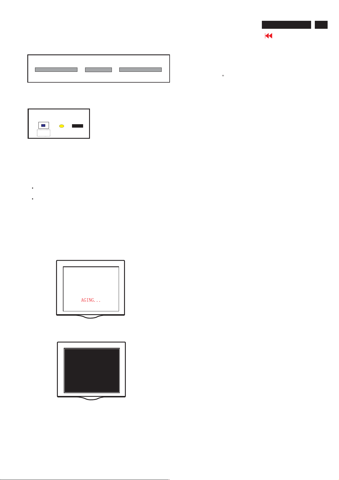
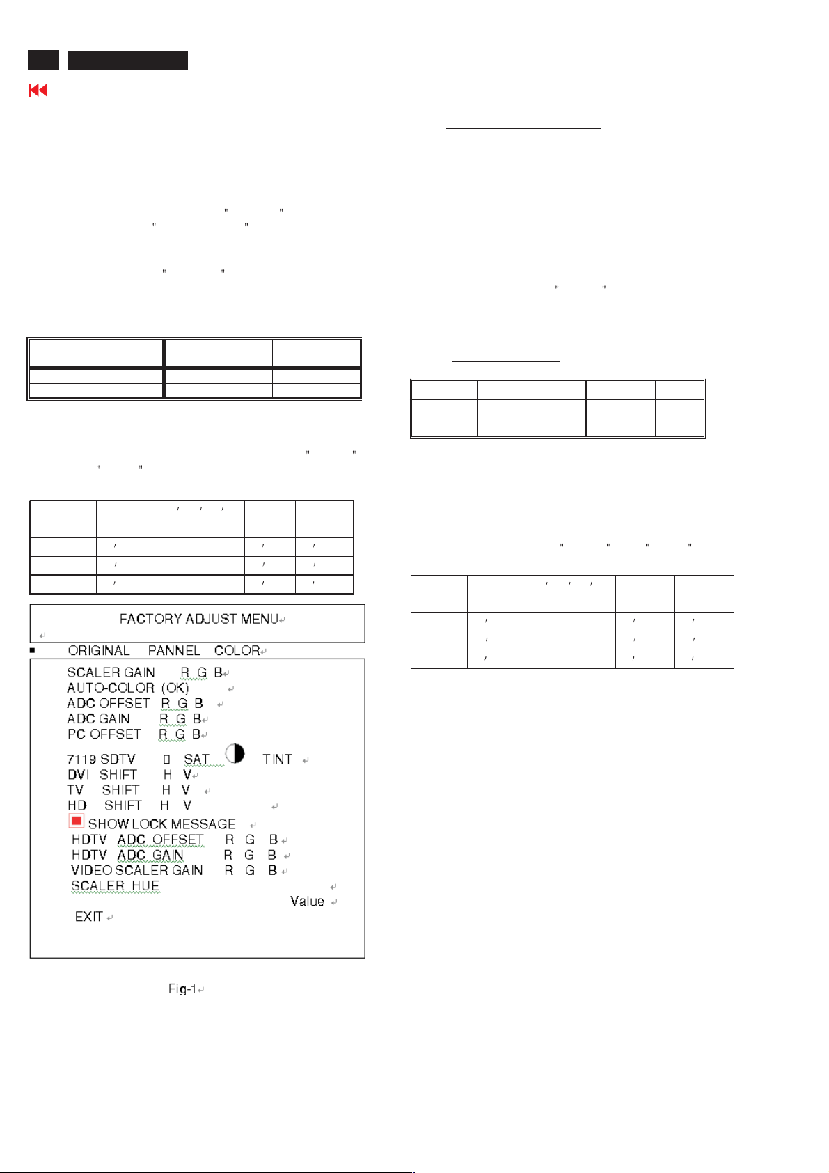
AGING MODE
No signal input ,power off -> on ,then Into the factory mode, , a full
white pattern will be display on the screen as Fig.1&Fig.2 in stead of
power saving mode. In other words, the power saving function will be
disable in the factory mode.Supply one signal for leaving aging mode.
Access Factory Mode
1). Turn off monitor.
2). Press power "Power " button.Then quickly push " Volume -"
and " Volume ",and hold this two buttons , then the screen
comes out "Waiting For Automatic Adjustment ",then the screen
will be black for one second untill comes out "Windows screen"]
=> then release this two buttons, then press "Menu" button, wait
until the OSD menu with Characters "F1/FL1 NAFTA V0.91.1
041124ADJUST" (below OSD menu) come on the Screen of the
monitor (see Fig. 3).
Fig.3
Scalar Gain R G B Scalar Gain for Normal/Warm/Cool in PC
mode.
Auto-Color Adjust color from received signal (either
in PC or HDTV mode).
ADC Offset R G B Adjust AD 9883 for PC ADC offset.
ADC Gain R G B Adjust AD 9883 for PC ADC gain.
PC Offset R G B PC analog scalar offset.
711X SDTV Brightness Adjust SA 7119 SDTV brightness.
711X SDTV SAT. Adjust SA 7119 SDTV saturation.
711X SDTV Contrast Adjust SA 7119 SDTV contrast.
711X SDTV TINT Adjust SA 7119 SDTV tint (hue).
TV Shift H V Adjust TV screen position
horizontally/vertically.
HD Shift H V Adjust HDTV screen position
horizontally/vertically.
Show Lock Message Show OSD lock message.
HDTVADCOffsetRGB AdjustAD9883forHDTVADCoffset.
HDTVADCGainRGB AdjustAD9883forHDTVADCgain.
Video Scalar Gain R G B Adjust scalar gain for Video mode.
Scalar Hue Adjust scalar hue.
Fig.1
Fig.2
Fig.4
10
26MF605W/17
Circuit Description
Go to cover page
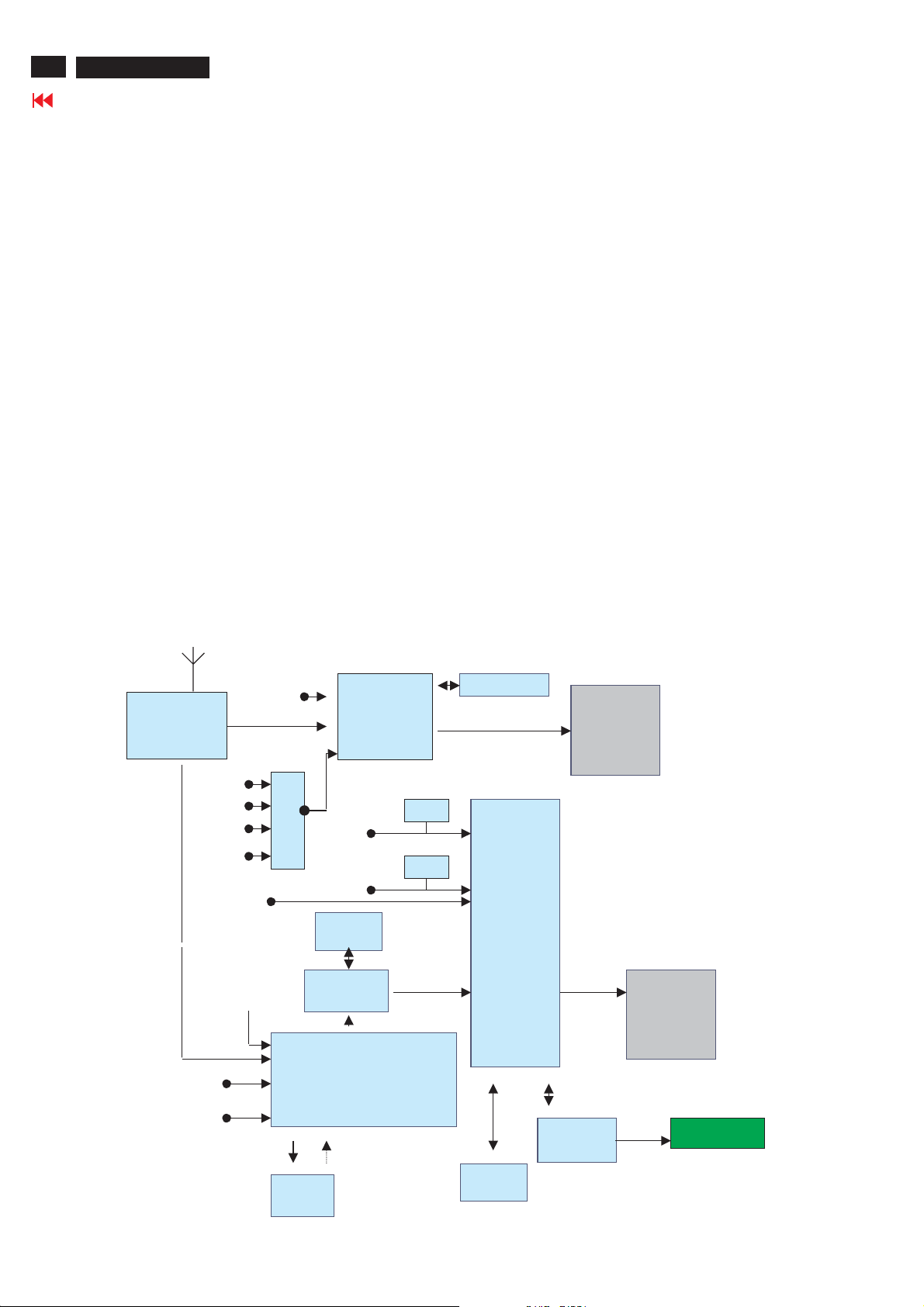
General Description
This LCD TV monitor using FL-1 platform. It can support PC analog signal ( via 15 pin D-Sub input ) and TV signal. It support PIP
function that is TV picture on PC graphic or TV picture on DVI /HDCP. It’s output resolution is up to 1366X768 75Hz for WXGA panel.
It can support DVI HDCP digital signal input and also support TV (RF) , CVBS/ RG B signal ( from SCART1 I/O for Europe model ) ,
CVBS / YC ( from SCART2 I/O for Europe model ) , CVBS/YPbPr ( from Cinch I/O for Non-Europe model ) , CVBS/YC ( from Cinch and S
terminal I/O for Non-Europe model ) , and also have side I/O , support CVBS/YC and Headphone for User easy used .
And It can also support Y Pb Pr signal input (from Cinch I/O) for 480I, 480P, 720P, 1080i 60Hz and 576I, 576P, 720P, 1080I 50Hz HDTV
format input.
Note : For Chinch I/O model two components input is provided one for 480I,480P and 576I, 576P the other for the 480I, 480P, 720P,
1080i 60Hz and 576I, 576P, 720P, 1080I 50Hz HDTV format input.
It also have PVR output function , support and monitor all the CVBS signal output with L/R sound.
This LCD monitor TV use MST51512 as Scaler engine, which has embedded Analog D-sub, digital DVI decoder, scaling input signal for
panel, OSD and simple 3D de-interlace. The extra SDRAM is to accomplish video frame rate conversion and PIP function.
The external CPU can be used for back light control, RC receiver, keypad input, I/O switch control , IIC communication and TV tuning
control, MSP34XX sound decoder control, SAA7119 video decoder control , Columbus IC ( 3D- comb filter ) control , and Audio AMP
TPA3004D sound control .
Video decoder SAA7119 is used for TV video processing and convert it with CCIR 601/16bits or 656/8bits digital format and send to
Columbus IC for 3D comb filter processing and noise reduction processing , after that then send to Scaler for de-interlace process.
One audio decoder MSP34XXG is used for TV sound processing, and output to Class D audio amplifier TPA3004D , then we can have 2
X10W audio output .
In Nafta model CC,V-chip data is decoded in SAA7119 and the scaler OSD display the CC information. The V-Chip is decode by SAA7119
and control via the MCU. In Europe model "Teletext display". Data decode is done by SAA5360, output RGB/FB is to video decoder input for
text overlapping. In non-text model( Nafta. Etc.), this chip is Not used .
Sound decoder
MSP34XX
DVI
HDCP
PC analogTuner CVBS
SDRAM
1Mx16
Columbus
3D
DDC
DDC
AUDIO delay
Scaler
MST51512
Audio
AMP
TPA3004D
LVDS
Panel
Tuner
video
audio
SC1-audio
SC2-audio
audio
DVI Audio
PC audio
HD YPbPr
RGB/YPbPr
AV3 audio
HD audio
2ndIF
M
U
X
SC2 YC , AV3 YC
SC1/SC2/AV3 CVBS
CVBS
MON_OUT
Video Decoder SAA7119
RGB/FB
TT
SAA5360
SDRAM
1Mx16
MCU 128K
Flash
Control Board
IR and key pad

Circuit Description
26MF605W/17
Go to cover page
MM tuner is used to receive RF wave and output CVBS and 2nd IF signal. CVBS is to video decoder
(SAA7119) for color process, 2nd IF is to sound decoder (MSP34x5) for audio process. The tuner control is via IIC ex. channel tuning.
For different TV system, tuner and sound decoder have diversity as above.
Standard TV input (Tuner, S-video, CVBS, SCART) is processed by SAA7119, But YPbPr, SDTV and HDTV(480i, 576i,
480p,576p,720p,1080i), is done by scaler MST51512L/502L ADC. But the signal is still link to SAA7119 if PIP (video in graph) function
is requested. Then all YPbPr signal processed by SAA7119 could be the PIP video source. (* May use down sampling in HD0)
MV protect is decoded by scaler.
Video decoder SAA7119, is in charge of color decoding, could support PAL, NTSC and SECAM world wide
system. Compare to SAA7118, SAA7119 improve some picture quality, like V-chip CC I2C read-back, LTI, CTI, skin tone
correction(see task A), also the HD0 is supported, so if F1 need PIP function then the The
Teltext function is for WE model, need a extra IC SAA5360. CVBS input, R/G/B, FB, out. Due to the SAA5360 request input signal
1Vrms and only one input channel, so the CVBS input source is from SAA7119 AOUT (CVBS out with 1Vrms). The R/G/B FB output
into SAA7119 by AI22/AI32/AI42, and AI44 could overlay on any video source.
Sound decoder MSP3415/45 is responsible to sound decode of tuner 2nd IF. It has one 2nd IF, two selectable audio sources input.
And one loudspeaker, one scart out. Due to the input port limitation, a MUX is added for AV source select( PC audio in is fix in SC1). If
the post audio amplifier is gain fixed type then the volume adjust will be on MSP34x5.
Scaler MST51502L/51512L besides scaling function, PIP, 3D de-interlacer, color enhance are major feature.
Even de-interlacer is not so good but for static picture is enough to avoid image sticking.
In America market, to avoid patent issue, two SDRAM is necessary for graph frame buffer. But in else region one SDRAM is
enough. Of course, if no PC mode in spec, then one SDRAM for all model.
The scaler structure limitation, the PIP source only from video port,8bitsor16bits. The sub window /PIP size can enlarge to half
screen.
MCU, NT68F632AL, is 128K flash ROM inside. Power control, RC5 I/O, and key function all done by here.
All chip communication is by IIC (SDA/SCL), and ISP is via DDCIIC, but if PC mode un-supported, then a reserved 6pin connector is
for same application.
11

12
26MF605W/17
Go to cover page
Front view
Mechanical Instruction
Back view
Step 1. Remove the stand.
Remove the three screws as Fig.3 and Fig.4
Fig.1
Fig.2
Fig.6
Fig.7
Fig.8
Fig.9
Fig.3
Step 2. Remove the Back cover as Fig.5~8.
a.
Remove the seven screws on the sides and the other
two screws as Fig.5
b. Use thin "I" type screwdriver to open 4 clicks on bottom
side as Fig.6
c.
Use thin "I" type screwdriver to open 3 clicks on right
side as Fig.7
e. Use thin "I" type screwdriver to open 3 clicks on left
side as Fig.8
f. Use thin "I" type screwdriver to open 4 clicks on top
side as Fig.9
g. Remove the back cover as Fig.10 ,then remove the
10 screws as Fig.10,Fig.11,Fig.12
Fig.4
Fig. 10
Fig. 11
Fig. 12
Step 3. Remove the Scaler and Power board.
Remove the 19 screws and disconnect the 9 cables as Fig. 13
and Fig.14
Fig.5

Fig. 13
Mechanical Instruction
Fig. 16
26MF605W/17
Go to cover page
13
Fig. 14
Step 4. Disconnect the HD PCB, the Side AV PCB, the KEY PCB , the
IR PCB, as Fig.15the Scaler PCB and power PCB
Fig. 15
Step 5 Remove the MAIN SHIELD ASSY as Fig.16~Fig.18
a.
Remove the 16 screws on the back side as Fig.16
b. on bottom side as Fig.17
Remove the 2 screws
c . on top side as Fig.18
Remove the 2 screws
d. Disconnect the MAIN SHIELD ASSY as Fig.19
Fig. 17
Fig. 18
Fig. 19
In warranty, it is not allowed to disassembly the LCD panel, even the
backlight unit defect.
Out of warranty, the replacment of backlight unit is a correct way
when the defect is cused by backlight (CCFL,Lamp).

14
26MF605W/17
Definition of Pixel Defects
Go to cover page
LCD Monitor Quality and Pixel Policy
The TFT monitor uses high-precision technology, manufactured according to HP standards, to guarantee
trouble-free performance. Nevertheless, the display may have cosmetic imperfections that appear as small
bright or dark spots.
This is common to all LCD displays used in products supplied by all vendors and is not specific to the HP LCD.
These imperfections are caused by one or more defective pixels or sub-pixels.
1. A pixel consists of one red, one green, and one blue sub-pixel.
2. A defective whole pixel is always turned on (a bright spot on a dark background), or it is always off (a dark spot
on a bright background). The first is the more visible of the two.3. A defective sub-pixel (dot defect) is less
2. visible than a defective whole pixeland is small and only visible on a specific background.The HP display does
not have more than:
4. bright dots.
5. dark dots.
6. total bright and dark dots.
7. No more than two adjacent (less than 2.5 mm edge-to-edge) defective pixels. To locate defective pixels, the monitor
should be viewed under normal operating conditions, in normal operating mode at a supported resolution and
refresh rate, from a distance of approximately 50 cm (16 in.).HP expects that, over time, the industry will continue to
improve its ability to produce LCDs with fewer cosmetic imperfections And HP will adjust guidelines as
improvements are made.

Warning Message
26MF605W/17
Go to cover page
1.Automatic adjustment (for factory only)
Press Volume+ and Volume- on front key at the same time (PC mode only). It adjusts PC image to the best and
save the screen automatically.
2.OUTOFRANGE
If PC input timing is out of range, it shows OUTOFRANGE warning message on the center of the screen.
range of horizontal frequency is between 14 - 63 KHz. The range of vertical frequency is between 45 The OSD won
t timeout.
3.NO VIDEO INPUT
When PC input timing has either horizontal frequency or vertical frequency. Or neither has horizontal frequency
nor vertical frequency. It shows on the center of the screen for 30 seconds, then it will enter sleep mode.
15
16
26MF605W/17
Go to cover page
Electrical Instructions
1. General points
1.1 During the test and measuring, supply a distortion free AC
mains voltage to the apparatus via an isolated transformer
with low internal resistance.
1.2 All measurements mentioned hereafter are carried out at a
normal mains voltage (90 - 132 VAC for NAFTA version,
195 -264 VAC for EUROPEAN version, or 90 - 264 VAC
for the model with full
range power supply, unless otherwise stated.)
1.3 All voltages are to be measurement or applied with respect
to ground, unless otherwise stated.
1.4 The test has to be done on a complete set including LCD
panel in a room with temperature of 25 +/- 5 degree C.
1.5 All values mentioned in these test instruction are only
applicable of a well aligned apparatus, with correct signal.
1.6 The letters symbols (B) and (S) placed behind the test
instruction denotes
(B): carried out 100% inspection at assembly line
(S): carried out test by sampling
1.7 The white balance (color temperature), has to be tested in
subdued lighted room.
1.8 Repetitive power on/off cycle are allowed except it should
be avoided within 6 sec.
2. Input and output signal
2.1.1 PC Signal type
Analog Video : 15 pin D-sub ,0.7 Vp-p linear, positive polarity
Separate Sync.: TTL level, separate, positive or negative polarity
Audio signal : 3.5mm stereo mini-jack
Level : -Nominal : 0.5 V rms.
- Maximum : 1.5 V rms.
-Impedance > 10 k W.
Signal source: pattern generator format as attachment
(table 1 to 5 ) Reference generator : CHROMA 2200 or 2250
2.1.2 TV Signal type
RF Signal : Aerial input / 10mV(80dBuV)
Video signal : Video( RCA jack, CVBS input) / 1Vpp (300mV-sync,
700mV-video.) S video input / 1VppY-signal, 300mVpp C-signal
COMP Video( RCA jack , YPbPr input) / 1Vpp Y signal ,
350mVpp Pb , Pr signal
DVI : Digital interface with 4 channels TMDS signal
Audio signal : Audio (1) R/L( RCA jack ) for AV IN1 ( share with
Video and S-video1 ).
Level: - Nominal : 0.5 V rms.
- Maximum : 1.5 V rms.
- Impedance > 10 k W.
Audio (2) R/L( RCA jack ) for AV IN2 (share with
Video2 and S-video2).
Level: - Nominal : 0.5 V rms.
- Maximum : 1.5 V rms.
- Impedance > 10 k W.
Audio (3) R/L ( RCA jack )for AV IN3 (share with
Video3 and Comp video).
Level: - Nominal : 0.5 V rms.
- Maximum : 1.5 V rms.
- Impedance > 10 k W.
Audio (4) R/L( RCA jack ) for DVI IN.
Level: - Nominal : 0.5 V rms.
- Maximum : 1.5 V rms.
- Impedance > 10 kW.
2.1.3 PVR output (CVBS output):
Video: CVBS output 1Vpp / Impedance : 75W.
Audio: R/L output (from CVBS)
Level: - Nominal : 0.5 V rms.
- Maximum : 1.5 V rms.
- Impedance < 1 kW.
2.1.4 Headphone
Audio: R/L output -10mW at 32W.
3.5mm stereo jack with switch
Impedance is between 8 and 600W.
2.2 PC Inpu t signal mode
2.2.1 PRESET VIDEO RESOLUTION
The analogue color LCD monitor must be capable of displaying
standard resolutions within the vertical frequency range of
58 - 63 Hz, and horizontal scan range of 30 - 50 KHz .
Use the CHROMA-2250 generator as the standard signal timing
source.
Dot rate (MHz) H.freq
(KHz)
1 25.175 31.469 IBM VGA 640*480 59.940
2 36.000 35.156 VESA 800*600 56.250
3 40.000 37.879 VESA 800*600 60.317
4 65.000 48.363 VESA 1024*768 60.004
5 74.500 44.772 WXGA 1280*720 59.855 CVT
5 79.500 47.776 WXGA 1280*768 59.87 CVT
Resolution recommend on 1280 X 720 @ 60Hz
Mode Resolution V.freq
(Hz)
Remar k
2.3 TV input signal Channel and pattern fo r NAFTA
model (Table1)
Signal Distribution Table (NTSC)
CH
A03 61.25MHz 65.75MHz NTSC M Color Circle
A06 83.25MHz 87.75MHz NTSC M Red Raster
A09 187.25MHz 191.75MHz NTSC M Circle Pattern
A11 199.25MHz 203.75MHz NTSC M Cross Hatch
A13 211.25MHz 215.75MHz NTSC M
A52 699.25MHz 703.75MHz NTSC M Color Bar
A69 801.25MHz 805.75MHz NTSC M 100% White
C70 499.25MHz 503.75MHz NTSC M Checkerboard
Table 1
Freq uenc y Carriers
Video Sound
TV System
Pattern
Two White
Window
Electrical Instructions
26MF605W/17
Go to cover page
17
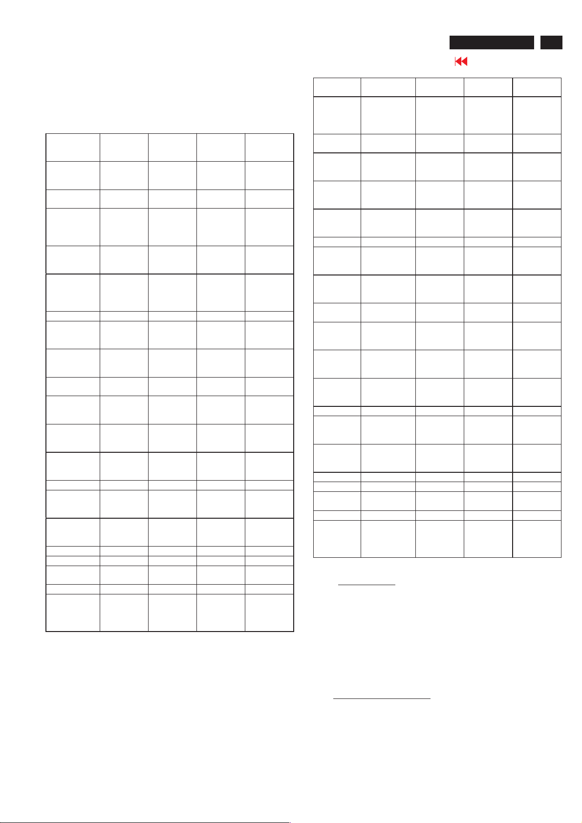
2.4 HD input mode
2.4.1 HD detail timing
(For Quantune Data setting with Q801GD or 802G in YpbPr mode)
Item
Pixel rate 74.25MHz
Horizontal
Frequency
Active 1920
Blank 280 pixels
Period 2200
Pulse delay 44 pixels
Pulse width 44 pixels
Vertical
Frequency
Active 1080 lines
Blank 45 lines
Period 1125 lines
Pulse delay 2 lines
Pulse width 5 lines
EQ before 0 line 0 line 0 line 0 line
EQ after 1 line 0 line 1 line 0 line
Scan Interlace ProgressiveInterlace Progressiv
Sync type ACS ACS ACS ACS
Video kind Analog
1920X108
0i 60Hz
(13.468
ns)
33.75KHz 45KHz 28.125KHz37.5KHz
pixels
(25.859
us)
(3.771 us)
pixels
(29.630
us)
(0.593 us)
(0.593 us)
60 Hz 60 Hz 50 Hz 50 Hz
(32.000
ms)
(1.333
ms)
(33.333
ms)
(0.059
ms)
(0.148
ms)
YPbPr
(ITU-R
BT.709)
1280X720
P 60Hz
74.25MHz
(13.468
ns)
1280
pixels
(17.239
us)
370 pixels
(4.983 us)
1650
pixels
(22.222
us)
70 pixels
(0.943 us)
40 pixels
(0.539 us)
720 lines
(16.0 ms)
30 lines
(0.667
ms)
750 lines
(16.667
ms)
5 lines
(0.111
ms )
5 lines
(0.111
ms)
Analog
YPbPr
(ITU-R
BT.709)
1920X108
0i50Hz
74.25MHz
( 13.468ns
)
1920
pixels
(25.859
us)
720 pixels
( 9.697
us )
2640
pixels
( 35.556
us )
484 pixels
( 6.519
us )
44 pixels
( 0.593
us )
1080 lines
( 38.4
ms )
45 lines
(1.6 ms )
1125 lines
(40ms)
2 lines
( 0.071
ms )
5 lines
(0.178
ms )
Analog
YPbPr
(ITU-R
BT.709 )
1280X720
P50Hz
74.25MHz
(13.468
ns)
1280
pixels
(17.239
us)
700 pixels
(9.428 us)
1980
pixels
(26.667
us)
400 pixels
(5.387 us)
40 pixels
(0.539 us)
720 lines
(19.2 ms)
30 lines
(0.8 ms)
750 lines
(20 ms)
5 lines
(0.133
ms )
5 lines
(0.133
ms)
e
Analog
YPbPr
(ITU-R
BT.709)
Item 720X576P
Pixel rate 27 MHz
Horizontal
Frequency
Active 720 pixels
Blank 144 pixels
Period 864 pixels
Pulse
delay
Pulse
width
Vertical
Frequency
Active 576 lines
Blank 49 lines
Period 625 lines
Pulse
delay
Pulse
width
EQ before 0 line 0 line 2 line 3 line
EQ after 0 line 0 line 2 line 3 line
Scan Progressive ProgressiveInterlace Interlace
Sync type ACS ACS ACS ACS
Video kind Analog
50Hz
(37.037 ns)
31.25 KHz 31.5KHz 15.625KHz15.734KH
(26.667 us)
(5.333 us)
(32.000 us)
12 pixels
(0.444 us)
64 pixels
(2.370 us)
50 Hz 60 Hz 50 Hz 59.94 Hz
(18.432 ms)
(1.568 ms )
(20.000 ms)
5 lines
(0.160 ms)
5 lines
(0.160 ms)
YPbPr
(SMP
TE RP177)
720X480P
60Hz
27.027MH
z
(37.000
ns)
720 pixels
(26.640
us)
138 pixels
(5.106 us)
858 pixels
(31.746
us)
16 pixels
(0.592 us)
62 pixels
(2.294 us)
480 lines
(15.238
ms)
45 lines
(1.429
ms)
525 lines
(16.667
ms)
9 lines
(0.287
ms)
6 lines
(0.190
ms)
Analog
YPbPr
(SMPTE
RP177)
Table 2
720X576i
50Hz
13.5MHz
( 74.074
ns )
720 pixels
(53.333
us)
144 pixels
( 10.667
us )
864 pixels
( 64.00
us )
12 pixels
( 0.889
us )
63 pixels
( 4.667
us )
576 lines
( 36.864
ms )
49 lines
(3.136
ms )
625 lines
(40ms)
2 lines
( 0.128
ms )
3 lines
(0.192
ms )
Analog
YPbPr
(SMPTE
RP177 )
720X480i
60Hz
13.5MHz
( 74.074
ns )
z
720 pixels
(53.333
us)
138 pixels
( 10.222
us )
858 pixels
( 63.556
us )
19 pixels
(1.407
us )
62 pixels
(4.593
us )
480 lines
( 30.507
ms )
45 lines
(2.860
ms )
525 lines
( 33.367
ms )
4 lines
(0.254
ms )
3 lines
(0.191
ms )
Analog
YPbPr
(SMPT
E RP177 )
3. Pow er supp ly
3.1 Setup the AC I/P at 264 VAC and 90VAC , and power board
3.2 Any adjustment is not needed.
provide two DC Output
1. The DC output voltage is 24V ± 1V DC for Inverter and
Scaler board Measured point between pin3(+24V) and
pin6(GND) at item 1001 of scaler board
2. The DC output voltage is 16V ± 1VDCforScalerand
Audio board Measured point between pin1(+16V) and
pin6(GND) at item 1001 of scaler board
4. TV Mode display adjust
4.1 White balance adjustment (B)
4.1.1 General set-up :
Equipment Requirements: Color analyzer.
Input requirements:
Input Signal Type : RF signal
1. Set to NTSC system, frequency=187.25MHZ ( for
NAFTA model ), with white pattern of 100%
18
26MF605W/17
Go to cover page
Electrical Instructions
2. Select Smart picture to Personal mode and check the x, y data.
Input Signal Strength : 10mV (80 dBuV) terminal voltage.
Input Injection Point : TV Tuner input
Alignment method:
Initial Set-up :
1.Set TV(7119) Brightness=142; Saturate =64,
Contrast =68 in Factory mode(can be fine tuned).
2. Set Smart picture as
3. Apply 100% Full White pattern by TV pattern
generator.
Alignment : Adjust the VIDEO SCALER GAIN RG B
Factory Mode
menu : press VOL+ and VOL- keys together around six
seconds]
1. Check (X, Y) co-ordinates as below:
Picture Mode
Normal (Original)
Table 3: Reading with Minolta CA-110.
2. Check the gray pattern should be distinguish and
color bar is correct
4.1.2 Set TV Color temperature in Factory mode as
and
COOL The VIDEO SCALER GAIN R\G\B value will be
followed below
Normal/ the R \G \B
are gain after alignment. WARM
R gain R R R -10
G gain G G -10 G -10
B gain B B -10 B
NORMAL . (See Fig 1.) [ Enter factory
0.289 ± 0.005 0.304 ± 0.005
Personal
xy
WARM ,
COOL
5. PC mode Display Adjustment
5.1 Display quality adjustment
Use timing mode as describe in 2.2, and use the POPO (pixel on pixel
off) pattern to adjust the clock until no stripe and adjust the phase until
clear picture.
Check all pre-set 6 modes.
5.2 WHITE-D ad justment (B )
in
.
5.2.1 At factory mode apply 1280X720 @60Hz mode with 32 gray
pattern.
Set smart picture at
Contrast to 50%.
Press AUTO-COLOR function for auto ADC offset and gain setup.
5.2.2 Apply full white pattern Set SCALER GAIN R G B
SCALER GAIN R G B.
1. Check (X, Y) co-ordinates as below :
Normal/ (8500°K)
x (center) 0.289 ± 0.015
y (center) 0.304 ± 0.015
Table 4: Reading with Minolta CA-110.
2. Check the gray level color poor & noise condition and chromaticity
Note: 1. Use Minolta CA-110 for color coordinates and luminance check.
2. Lumin ance> 400 cd/m
Original (NORAML)color and PC Brightness control; Contrast
control at 100%
5.2.3 Set Smart picture as
The SCALER GAIN R\G\B value will be followed below
Normal/ the R \G \B
are gain after alignment.
R gain R R R -10
G gain G G -10 G -10
B gain B B -10 B
5.3 Check th e digital in terface c able (B )
Check the 64 gray level color poor & noise condition.
Normal , and Brightness to 50% and
= VIDEO
2
in the center of the screen at
WARM , and COOL
WARM COOL
.
6. HDTV Mode display adjust
6.1 White balance adjustment (B)
General set-up:
Equipment : Quantum Data Pattern Generator 801GD or 802G.
Or FLUKE 54200, apply 576i, DIGITAL SCAN/DIGI_ADC1 pattern.
Apply 1080i, RGBW(177=Infocus2) gray pattern.
Electrical Instructions
.
26MF605W/17
Go to cover page
19
Alignment method:
Initial Set-up: 1.Set Smart picture as
Alignments : Set HD VIDEO SCALER GAIN R\G\B= TV
Check (X, Y) co-ordinates as below:
Picture Mode x y
Personal
If chromaticity (X, Y) co-ordinates is out of specification,
re-alignment Video scalar R/G/B gain from 127/127/127.
7. Preset DVI HDCP Key
7.1 Download HDCP Key
The 284 bytes HDCP key should be download to the TV set via
IF cable using ATE at factory Alignment tools
7.2 DVI Video HDCP Key Test
7.2.1Use pattern generator
Equipment: Quantum 802R or 802BT or equivalent equipments.
Pattern : Standard HDCP Pattern (It
Timing : 720 X 480P 60Hz
Result : The PASS information should be shown on the screen.
7.2.2 Use DVD Player:
Equipment: 1.Pioneer (model: DV-S969AVi) or equivalent equipments
Result : The picture should be shown Normally.
8. Preset EEPROM d ata
EEPROM data has to be preset data according following table.
8.1 Factory mo de preset .
Function
SCALER GAIN
ADC Off set R/G/B
ADC Gain R/G/B
PC OFFset R/G/B
7119 brightness
7119 Satur ation #1
7119 contrast
7119 TINT
DVI SHIFT H
DVI SHIFT V
TV sh ift H
TV sh ift V
HD SHIFT H
HD SHIFT V
HD ADC OFFs et R G B
HD ADC GAIN R G B
Video Scaler Gai n
Scaler Hue
Color=60, Contrast=65)
2.Press AUTO-COLOR process.
Normal VIDEO SCALER GAIN R G B.
1. Apply
2. Check the gray pattern should be
distinguish and color bar is correct
720 X 576P 50Hz
1280X 720P 50Hz
1280X 720P 60Hz
1920X1080i 50Hz
1920X1080i 60Hz
2.DVD disk with Macro Vision protection.
Regu lar
100% Full White pattern by Quantum
DATA 802G pattern generator.
0.289 ± 0.015 0.304 ± 0.015
Personal , Brightness=48,
s color bar)
Preset value
127 127 127
127 127 127
127 127 127
127 127 127
#1
#1
#1
#2 #2
#2 #2
NTSC PAL
175 195
15 1
#3 #3
#3 #3
127 127 127
127 127 127
127 127 127
50
#1
PERSONAL/
NORMAL
TV 139 64 60 24
AV 142 64 64 24
S-Video 142 64 64 24
Component 143 70 62 --
#2
480P576P720P/
DVI shift H 22 22 96 55 103 48
DVIshiftV445040406060
#3
480i480P576i576P720
HD
shift H155
HD
shift V
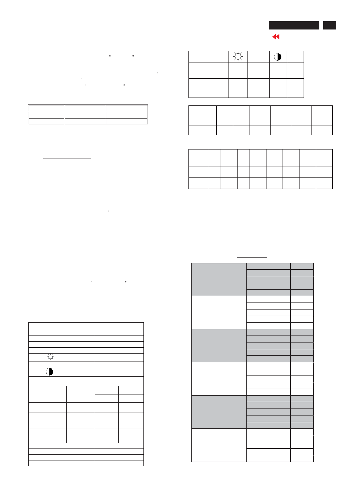
8.2 Smart picture & Smart sound:
8.2.1 Final TV mode out box setting.
Smart Picture : Sport Color Temp in Factory mode : COOL
Smart Sound : Personal
PERSONAL
MOVIES
SPORTS
WEAK SIGNAL
MULTIMEDIA
NIGHT
154 16716710814679 79
39 40 49 53 39 39 58 58
SOUND VOLUME : 10
BASE : 55
TREBLE : 55
Balance :0
Virtual SURROUND : OFF
AVL : NO
SAT. TINT
50Hz
Smart Pic ture
BRIGHTNESS 45
COLOR 50
CONTRAST 65
SHARPNESS 38
TINT 50
BRIGHTNESS 59
COLOR 60
CONTRAST 51
SHARPNESS 36
TINT 50
BRIGHTNESS 48
COLOR 65
CONTRAST 75
SHARPNESS 46
TINT 50
BRIGHTNESS 52
COLOR 60
CONTRAST 51
SHARPNESS 46
TINT 50
BRIGHTNESS 52
COLOR 60
CONTRAST 68
SHARPNESS 33
TINT 50
BRIGHTNESS 45
COLOR 50
CONTRAST 65
SHARPNESS 38
TINT 50
720P/
60Hz
P/50
Hz
720
P/60
Hz
1080i/
50Hz
1080
i/50
Hz
1080i/
60Hz
1080
i/60
Hz
20
26MF605W/17
Go to cover page
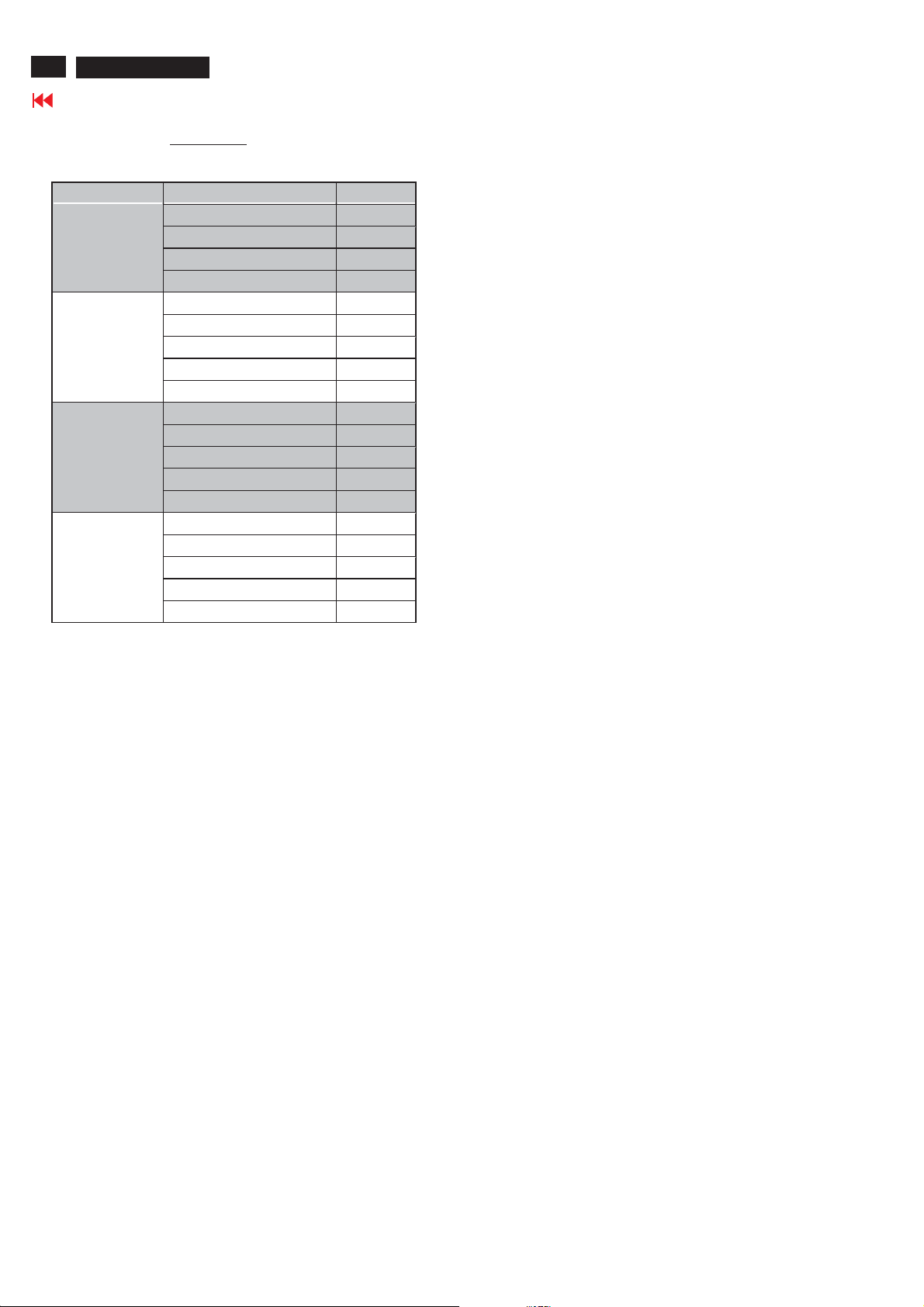
Electrical Instructions
EQ Setting
PERSONAL
NEWS
MUSIC
THEATRE
Smart Sound
EQBAND1 120Hz +25
EQ BAND2 500Hz +25
EQ BAND3 1.5KHz +25
EQ BAND4 5KHz +25
EQ BAND5 10KHz +25
EQ BAND1 120Hz 0
EQ BAND2 500Hz 0
EQ BAND3 1.5KHz +20
EQ BAND4 5KHz +30
EQ BAND5 10KHz +40
EQ BAND1 120Hz +50
EQ BAND2 500Hz +35
EQ BAND3 1.5KHz +15
EQ BAND4 5KHz +30
EQ BAND5 10KHz +45
EQ BAND1 120Hz +50
EQ BAND2 500Hz +35
EQ BAND3 1.5KHz -5
EQ BAND4 5KHz +20
EQ BAND5 10KHz +40
DDC Instructions
26MF605W/17
Go to cover page
21
General
DDC Data Re-programming
In case the DDC data memory IC or main EEPROM which storage all
factory settings were replaced due to a defect, the serial numbers have
to be re-programmed "Analog DDC IC, Digital DDC IC & EEPROM".
It is advised to re-soldered DDC IC and main EEPROM from the old
board onto the new board if circuit board have been replaced, in this case
the DDC data does not need to be re-programmed.
Additional information
Additional information about DDC (Display Data Channel) may be
obtained from Video Electronics Standards Association (VESA).
Extended Display Identification Data(EDID) information may be also
obtained from VESA.
System and equipment requirements
1. An i486 (or above) personal computer or compatible.
2. Microsoft operation system Windows 95/98 .
Y o Install the EDID_PORT_Tool under Win2000/XP . As
ou have t
Fig. 1 .
A. Cody the "UserPort.sys" to C:\WINNT\system32\drivers(win2000)
C:\WINDOWS\system32\drivers(winXP)
B. Running " io.exe" everytime, Before you start to programming
edid data .
Fig. 1Fig.
1
Note: The alignment box has already build-in a batteries socket for
using batteries (8~12V) as power source. Pull out the socket by
remove four screws at the rear of box. Please do not forget that
remove batteries after programming. The energy of batteries can
only drive circuits for a short period of time.
To Printer port
DC 8~12V
To Monitor
D-sub/DVI cable
Power
indicator
Fig. 3
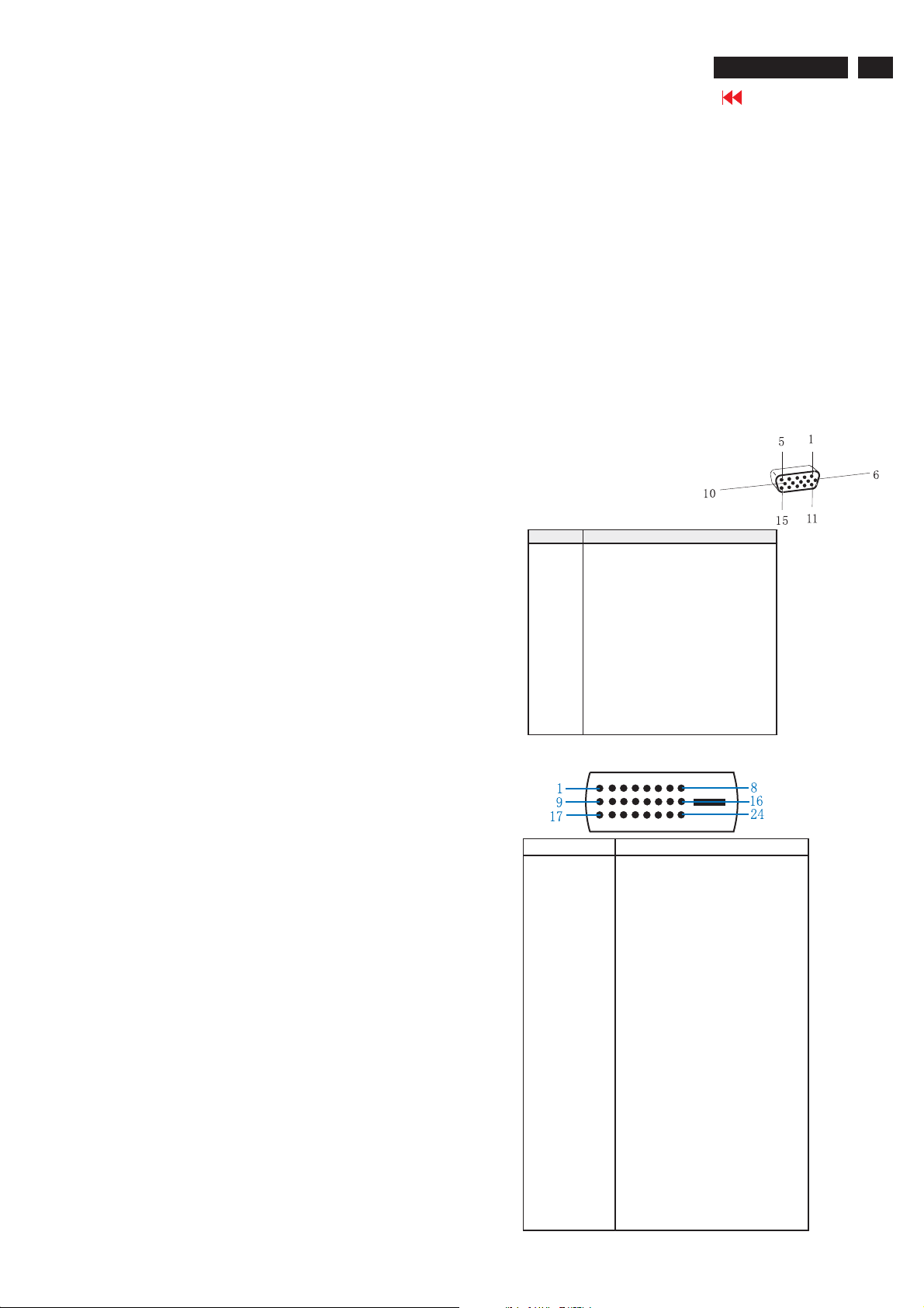
Pin assignment
A. 15-pin D-Sub Connector
PIN No. SIGNAL
1 Red video input
2 Green video input / sync on green
3 Blue video input
4GND
5 GND - Cable detect
6RedvideoGND
7 Green video GND
8 Blue video GND
9DDC+3.3Vor+5V
10 Logic GND
11 GND
12 Serial data line (SDA)
13 H-sync / H+V
14 V-sync
15 Data clock line (SCL)
B. Input DVI -D Connector pin
3. EDID46.EXE program
4. A/D Alignment kits (12NC: 3138 106 10079):
inclusion : a. Alignment box x1 (Fig. 2)
b. Printer cable x1
c. (D-Sub) to (D-Sub) cable x1
D. (D-Sub) to (DVI) cable x1
Fig. 2
Pin No. Description
1 T.M.D.S. data2-
2 T.M.D.S. data2+
3 T.M.D.S. data2 shield
4 No Connect
5 No Connect
6 DDC clock
7 DDC data
8 No Connect
9 T.M.D.S. data1-
10 T.M.D.S. data1+
11 T.M.D.S. data1 shield
12 No Connect
13 No Connect
14 +5V Power
15 Ground (for +5V) - Cable detect
16 Hot plug detect
17 T.M.D.S. data0-
18 T.M.D.S. data0+
19 T.M.D.S. data0 shield
20 No Connect
21 No Connect
22 T.M.D.S clock shield
23 T.M.D.S. clock+
24 T.M.D.S. clock-
22
26MF605W/17
Go to cover page
DDC Instructions
Configuration and procedure
There is no Hardware DDC (DDC IC) anymore. Main EEPROM stores
all factory settings and DDC data (EDID code) which is also called
Software DDC. The following section describes the connection and
procedure for Software DDC application. The main EEPROM can be reprogrammed by enabling '' factory memory data write'' function on the
DDC program (EDID46.EXE).
Initialize alignment box
In order to avoid that monitor entering power saving mode due
to sync will cut off by alignment box, it is necessary to initialize
alignment box before running programming software
(EDID46.EXE). Following steps show you the procedures and
connection.
Step 1: Supply 8-12V DC power source to the Alignment box by
plugging a DC power cord .
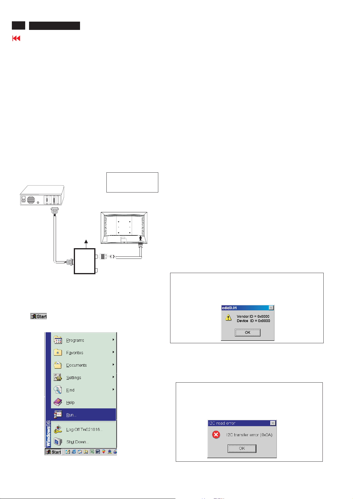
Step 2: Connecting printer cable and D-Sub cable of monitor as Fig. 4
PC
1= Power connector
2= D-SUB connector
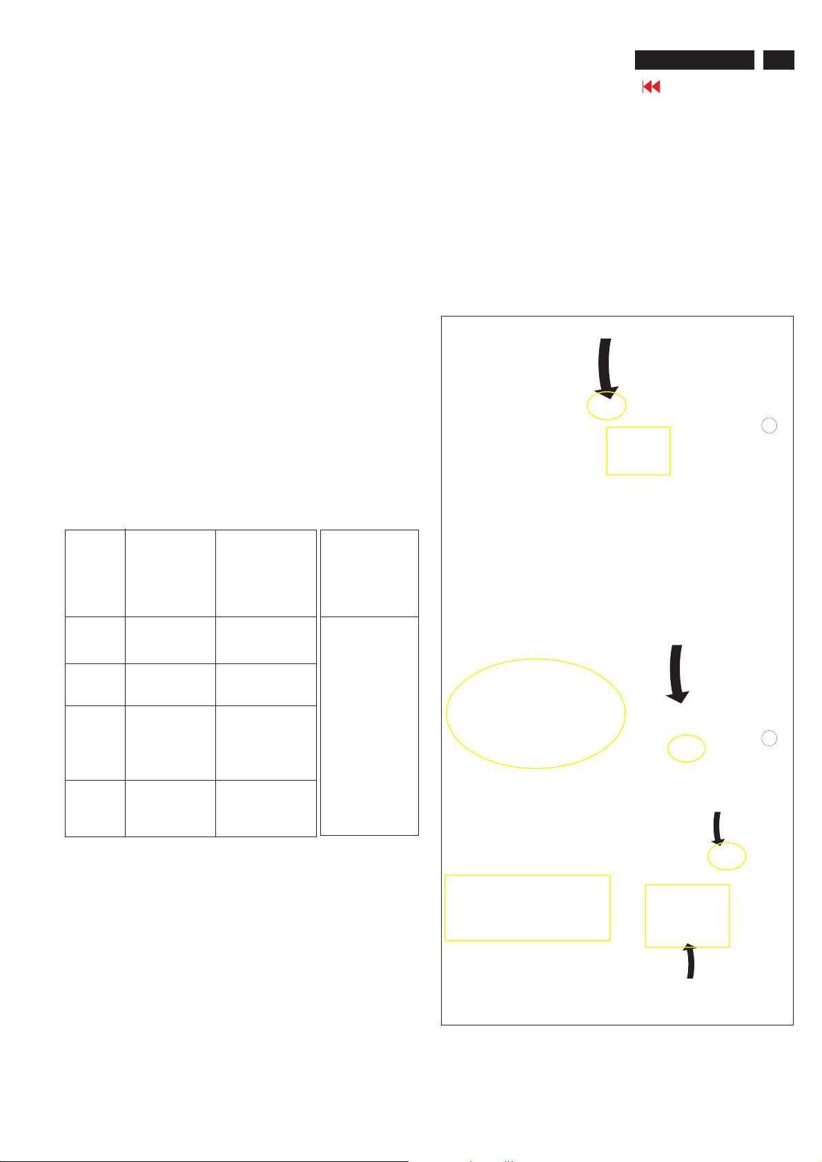
3. At the submenu, type the letter of your computer's hard disk drive
followed by :EDID46 (for example, C:\EDID46, as shown in Fig. 6).
1
Fig. 6
4. Click OK button. The main menu appears (as shown in Fig. 7).
This is for initialize alignment box.
DC Power
8-12 V
Fig. 5
----->
2
----->
To printer port (LTP1)
Step 3: Installation of EDID46.EXE
Method 1: Start on DDC program
Start Microsoft Windows.
1. The Program"EDID46.EXE" in service manual cd-rom be copyed to C:\ .
2. Click , choose Run at start menu of Windows as shown
In Fig. 5.
Printer
Port
To
Monitor
To PC
1
Fig. 4
Fig. 7
Note 1: If the connection is improper, you will see the following error
message (as shown in Fig. 8) before entering the main menu.
Meanwhile, the (read EDID) function will be disable. At this
time, please make sure all cables are connected correctly and
fixedly, and the procedure has been performed properly.
Fig. 8
Note 2: During the loading, EDID46 will verify the EDID data which just
loaded from monitor before proceed any further function, once
the data structure of EDID can not be recognized, the following
error message will appear on the screen as below. Please
confirm following steps to avoid this message.
1. The data structure of EDID was incorrect.
2. DDC IC that you are trying to load data is empty.
3. Wrong communication channel has set at configuration setup
windows.
4. Cables loosed or poor contact of connection.
Fig. 9
DDC Instructions
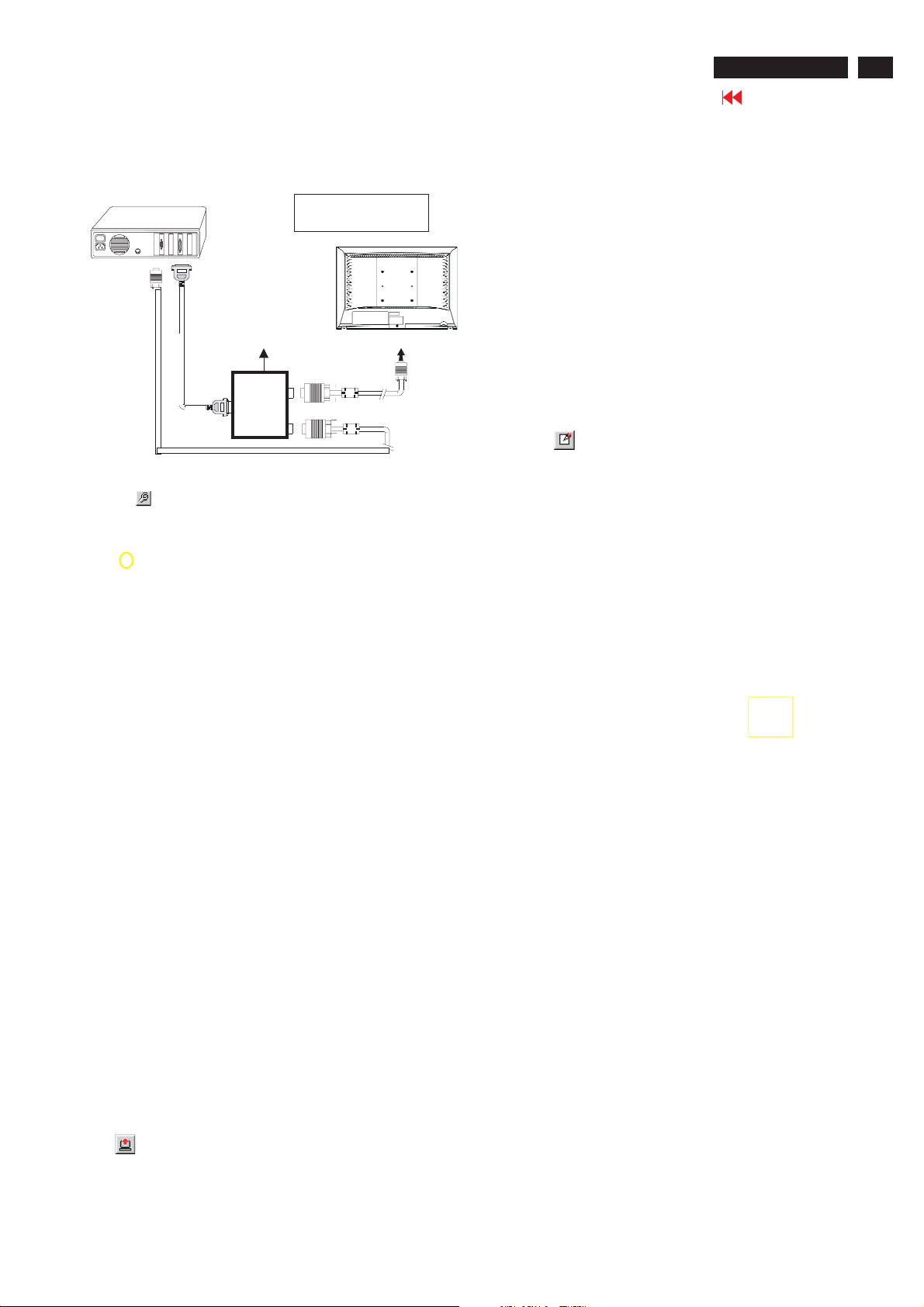
Re-programming Analog DDC IC
Step 1: After initialize alignment box, connecting all
cables and box as shown in Fig. 10.
PC
1=Power connector
2= D-SUB connector
26MF605W/17
Go to cover page
23
DC Power
8-12V
To printer port (LTP1)
To PC Video port (D-sub)
Printer
Port
To
Monitor
To PC
1
2
----->
----->
Step 2: Read DDC data from monitor
1. Click icon as shown in Fig. 11 from the tool bar to bring up
the Channels "Configuration Setup" windows as shown in Fig. 11.
=====>
Click this button
Fig. 11
2. Select the DDC2Bi as the communication channel.
As shown in Fig. 12.
Fig. 10
Fig. 13
Step 3: Modify DDC data (verify EDID version, week,
year)
Click (new function) icon from the tool bar, bring up
Step 1 of 9 as shown in Fig. 14 .
EDID46 DDC application provides the function selection and
Select and fill out,
If necessary.
Fig. 14
Fig. 12
3. Click OK button to confirm your selection.
4. Click icon (Read EDID function) to read DDC EDID data from
monitor. The EDID codes will display on screen as shown in Fig. 13.
Step 4: Modify DDC data (Monitor Serial No.)
1. Click Next , bring up Fig. 15.
Fig. 15

24
26MF605W/17
Go to cover page
DDC Instructions
2. Click Next , bring up Fig.16.
3. Click Next , bring up Fig.17.
5. Click Next , bring up Fig.19.
Fig. 19
Fig. 16
6. Click Next , bring up Fig. 20.
In this step, please confirm the Descriptor Data Type is
Monitor Range Limits, and all the items are same as below.
4. Click Next , bring up Fig.18.
Fig. 17
Fig. 18
Fig. 20
7. Click Next , bring up Fig. 21.
Fig. 21
DDC Instructions
8. Click Next , bring up Fig. 22.
- Click Finish to exit the Step window.
- Serial number can be filled up at this moment (for example,
26MF605002).
NOTE: You must modify the Serial NO. In step 9, otherwise the Serial NO.
In OSDCouldn't be modified correctly.
Fig. 22
26MF605W/17
25
Go to cover page
4). Click (Write EDID) icon from the tool bar to write DDC data. then
the screen will be black for 2-3 seconds,then the screen recovers,
and "ATTENTION NO VIDEO INPUT"will come on the screen of the
monitor,wait for 20-30 seconds ,DDC data will be finished Writing.
Step 6: Save DDC data
Sometimes, you may need to save DDC data as a text file
for using in other IC chip. To save DDC data, follow the
steps below:
1. Click (Save) icon (or click "file"-> "save as") from the tool
bar and give a file name as shown in Fig. 25.
The file type is EDID46 file (*.ddc) which can be open in
WordPad. By using WordPad, the texts of DDC data & table
(128 bytes, hex code) can be modified. If DDC TEXTS &
HEX Table ar completely correct, it can be saved as .ddc flie
to re-load it into DDC IC for DDC Data application.
Step 5: Write DDC data
1. Configuration should be as Fig. 23. And press OK.
2. Access Factory Mode
1). Turn off monitor.
2). Press power "Power " button.Then quickly push"Volume -"
and " Volume ",and hold this two buttons,then the screen
comes out "Waiting For Automatic Adjustment ",then the screen
will be black for one second ,untill comes out "Windows screen"]
=> then release this two buttons, then press "Menu"button, wait
until the OSD menu with Characters "F1/FL1 NAFTA V0.91.1
041124ADJUST" (below OSD menu) come on the Screen of the
monitor (see Fig. 24).
Fig. 23
Fig. 25
2. Click Save.
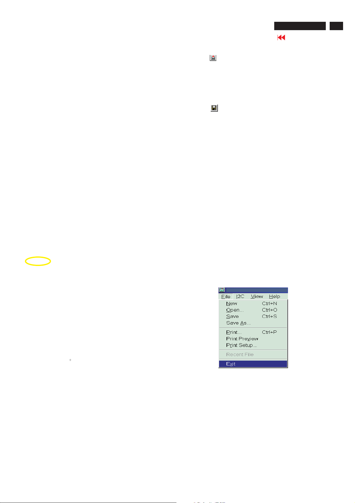
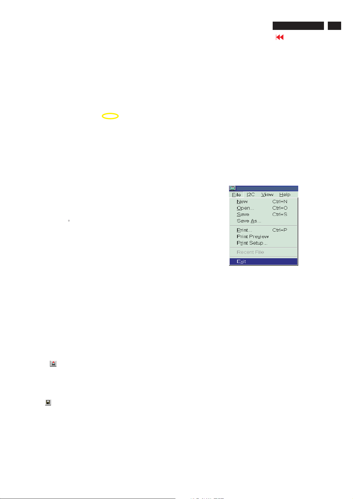
Step 7: Exit DDC program
Pull down the File menu and select Exit as shown in Fig. 26.
Fig. 26
Step 8: Turn off the monitor, exit the factory mode.
3) Push Menu to exit OSDmenu.""
Fig. 24
----------------->
Factory Mode
Indicator
26
26MF605W/17
Go to cover page
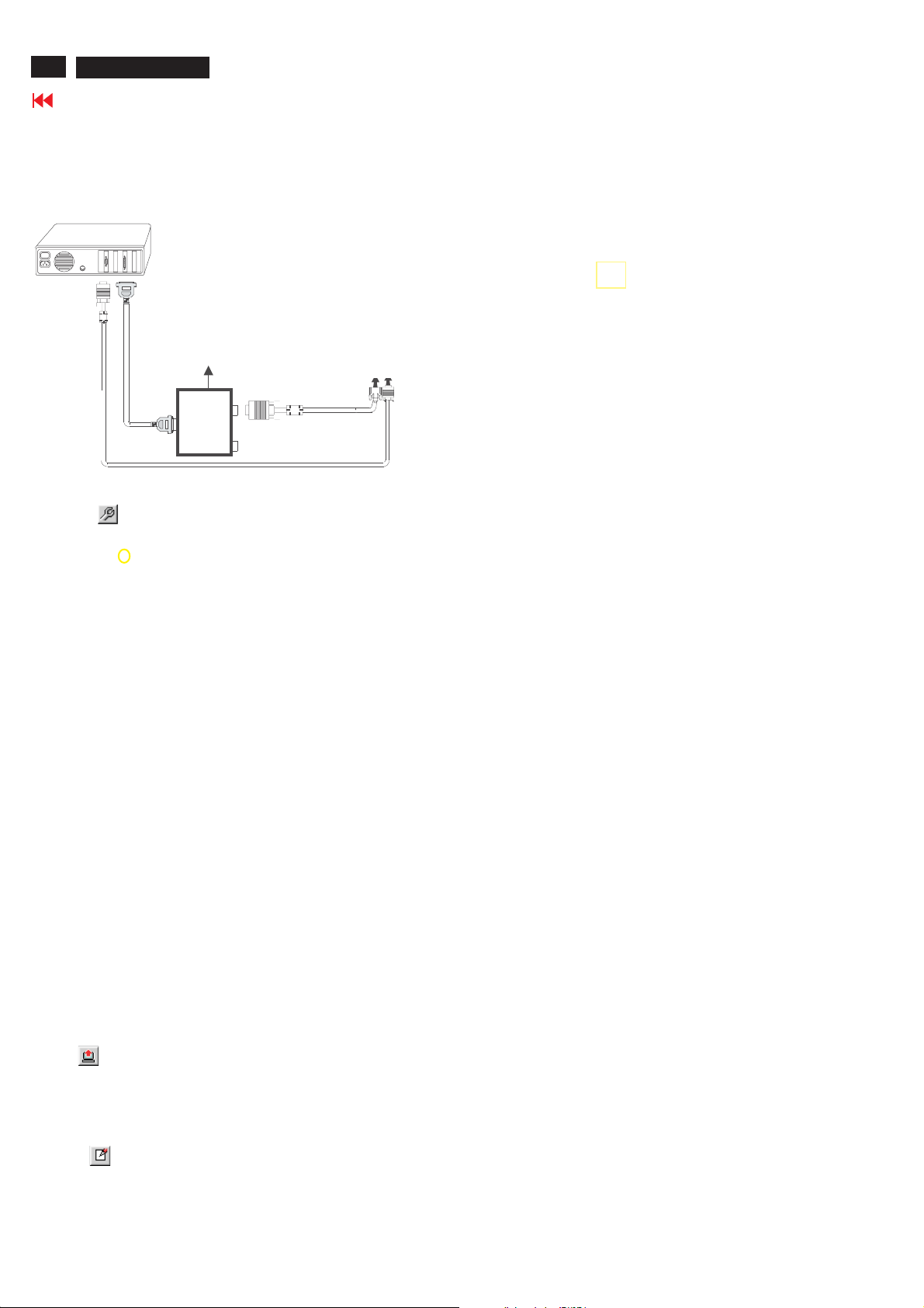
Re-programming Digital DDC IC
Step 1: After initialize alignment box, connecting all
cables and box as shown in Fig. 27.
PC
1=DVI-D connector
2=D-sub connector
3=Power Plug
DDC Instructions
Select and fill out,
If necessary.
DC Power
~
8 12V
To video card
To printer port (LTP1)
Printer
Port
D-sub to DVI-D cable
To
Monitor
Step 2: Read DDC data from monitor
D-sub cable
3
1
2
Fig. 27
1. Click icon as shown in Fig. 11 from the tool bar to bring up
the Channels "Configuration Setup" windows as shown in Fig. 28.
=====>
Click this button
Fig. 28
2. Select the DDC2Bi as the communication channel.
As shown in Fig. 29.
Fig. 31
Step 4: Modify DDC data (Monitor Serial No.)
1. Click Next , bring up Fig. 32.
2. Click Next , bring up Fig. 33.
3. Click Next , bring up Fig. 34.
Fig. 33
4. Click Next , bring up Fig. 35.
5. Click Next , bring up Fig. 36.
Fig. 34
Fig. 32
Fig. 29
Fig. 30
3. Click OK button to confirm your selection.
4. Click icon (Read EDID function) to read DDC EDID data from
monitor. The EDID codes will display on screen as shown in Fig. 30.
Step 3: Modify DDC data (verify EDID version, week,
year)
Click (new function) icon from the tool bar, bring up
Step 1 of 9 as shown in Fig. 31 .
EDID46 DDC application provides the function selection and
text change (select & fill out) from Step 1 to Step 9.
Fig. 35
6. Click Next , bring up Fig. 37.
In this step, please confirm the Descriptor Data Type is
Monitor Range Limits, and all the items are same as below.
7. Click Next , bring up Fig. 38.
Fig. 37
Fig. 36
Fig. 38
DDC Instructions
8. Click Next , bring up Fig. 39.
- Click Finish to exit the Step window.
- Serial number can be filled up at this moment (for example,
26MF605002).
NOTE: You must modify the Serial NO. In step 9, otherwise the Serial
NO. In OSD Couldn't be modified correctly.
26MF605W/17
Go to cover page
27
Fig. 39
Fig. 40
Step 5: Write DDC data
1. Configuration should be as Fig. 40. And press OK.
2. Access Factory Mode
1). Turn off monitor.
2). Press power "Power " button.Then quickly push " Volume -"
and " Volume ",and hold this two buttons,then the screen
comes out "Waiting For Automatic Adjustment ",then the screen
will be black for one second ,untill comes out "Windows screen"]
=> then release this two buttons, then press "Menu" button, wait
until the OSD menu with Characters "F1/FL1 NAFTA V0.91.1
041124ADJUST" (below OSD menu) come on the Screen of the
monitor (see Fig. 41).
----------------->
Factory Mode
2. Click Save.
Fig.42
Step 7: Exit DDC program
Pull down the File menu and select Exit as shown in Fig. 43.
Fig. 43
Step 8: Turn off the monitor, exit the factory mode.
Indicator
Fig. 41
3) Push Menu to exit OSD menu.""
3. Click (Write EDID) icon from the tool bar to write DDC data.
Then wait for 20-30 seconds ,DDC data will be finished Writing.
Step 6: Save DDC data
Sometimes, you may need to save DDC data as a text file for using
in other IC chip. To save DDC data, follow the steps below:
1. Click (Save) icon (or click "file"-> "save as") from the tool bar and
give a file name as shown in Fig. 42.
The file type is EDID46 file (*.ddc) which can be open in WordPad. By
using WordPad, the texts of DDC data & table (128 bytes, hex
code) can be modified. If DDC TEXTS & HEX Table ar completely
correct, it can be saved as *.ddc flie to re-load it into DDC IC for DDC
Data application.
28
26MF605W/17
Failure Mode Of Panel
Go to cover page
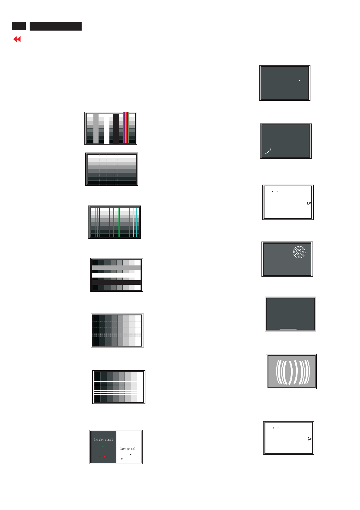
Quick reference for failure mode of LCD panel
this page presents problems that could be made by LCD panel.
It is not necessary to repair circuit board. Simply follow the mechanical
instruction on this manual to eliminate failure by replace LCD panel.
Polarizer has bubbles
Failure description
Vertical block defect
Vertical dim lines
Vertical lines defect
(Always bright or dark)
Horizontal block defect
Phenomenon
Polarizer has bubbles
Foreign material inside
polarizer. It shows liner or
dot shape.
Concentric circle formed
Horizontal dim lines
Horizontal lines defect
(Always bright or dark)
Has bright or dark pixel
Bottom back light of LCD is
brighter than normal
Back light un-uniformity
Backlight has foreign material.
Black or white color, liner or
circular type
SafetyTest Requirements
26MF605W/17
Go to cover page
29
All units that are returnedfor service or repair mustpass the
originalmanufacturessafety tests. Safety testingrequiresboth
and testing.Hipot Ground Continuity
HI-POT TEST INSTRUCTION
1.Application requirements
1.1 All mains operated products mustpass the Hi-Pot testas
describedinthis instruction.
1.2 This test must be performed again after thecovershave
been refittedfollowingthe repair, inspection or modification
of theproduct.
2.
Test method
2.1 Connectingc
2.1.1 Thetest specified must be appliedbetween the parallel-
bladeplugof the mainscord and all accessible metal
parts of theproduct.
2.1.2 Before carryingoutthetest, reliableconductive
connections
maintained throughoutthetest period.
2.1.3 The mains switch(es) must be in the "ON" position.
2.2 Test Requirements
All productsshould be HiPot and Ground Continuity tested as
follows:
onditions
must beensured and thereafter be
3. Equipments and Connection
3.1. Equipments
For example :
-ChenHwa9032 PROGRAMMABLE AUTO SAFETY
TESTER
-ChenHwa 510BDigital Grounding ContinuityTester
-ChenHwa 901 (AC Hi-pot test), 902 (AC, DC Hi-pot test)
Withstanding Tester
3.2.Connection
*Turn on thepower switch ofmonitor before Hipot and
Ground Continuity testing.
Clip
Clip
Condition HiPot Test for HiPot Test for Ground Continuity
voltage (2000VAC) (1200VAC) 25A,AC
Testtime 3seconds 1 second 3 seconds(min.)
(min.) Resistance
Trip set at 100 uA 5 mA <=0.09+Rohm,
current for Max. R is the
(Tester)
Ramp set at 2
time seconds
(Tester)
2.2.1 The minimum test durationfor QualityControlInspector
2.2.2 Thetestvoltage must be maintainedwithin the specified
productswhere productswhere Testrequirement
the mains inputthe mains input is
range is Full 110V AC(USA
range(or 220V type)
AC)
Test2820VDC 1700VDC
limitation; set resistance of
at 0.1 uA for the mains cord.
Min. Limitation
must be1minute.
voltage + 5%.
Testcurrent:
Testtime:
required:
(ChenHwa 9032 tester)
Video cable
Connect the "video cable"
or "grounding screw"
to the CLIP on your tester.
Grounding screw
Connect the power cord
to the monitor.
2.2.3 There must be no breakdown duringthetest.
2.2.4 Thegrounding bladeo
conductedwith accessible metal parts.
rpin ofmains plug must be
Power outlet
4. Recording
Hipot and Ground Continuity testing records have to be kept
for a period of 10 years.
(Rear view of monitor)
30
26MF605W/17
ISP Instructions
Go to cover page
Configuration and procedure
"Easywriter " The software is providedbyNovatek to upgradethe
firmware of CPU.
It is a windows-based program, which cannot be run in MS-DOS.
DDC2BI_ISP TOOL (3138 106 10396) is for the interface between
"Parallel Port of PC" and "15 pin-D-SUB connector of Monitor".
System and equipment requirements
1. An i486 (or above) personal computer or compatible.
2. Microsoft operation system Windows 95/98/2000/XP.
3. ISP Software " Easywriter "
4. as showninFig. 1
DDC2BI_ISP TOOL (3138 106 10396)
D-SUB to monitor
Step 3 :Copy the FL1_NAFTA_26_V120_3A10.hex to C:\26MF605W-17
as shown in Fig. 4 .
Lenovo CK5S5
ParallelPorttoPrintPortinPC
Fig. 1
5. Connect and Mains cord to Monitor as shown
in Fig. 2.
Connect to
Mains cord
6. Install and setup the Easywriter program
DDC2BI_ISP TOOL
Monitor (A)
Video cable
Fig.2
PC
To v i deo card
26MF605W-17 -Monitor (B)
D-Sub
Connect to Mains
cord at this moment.
ISP box
To printer port (LTP1)
------------------------------->
Fig.4
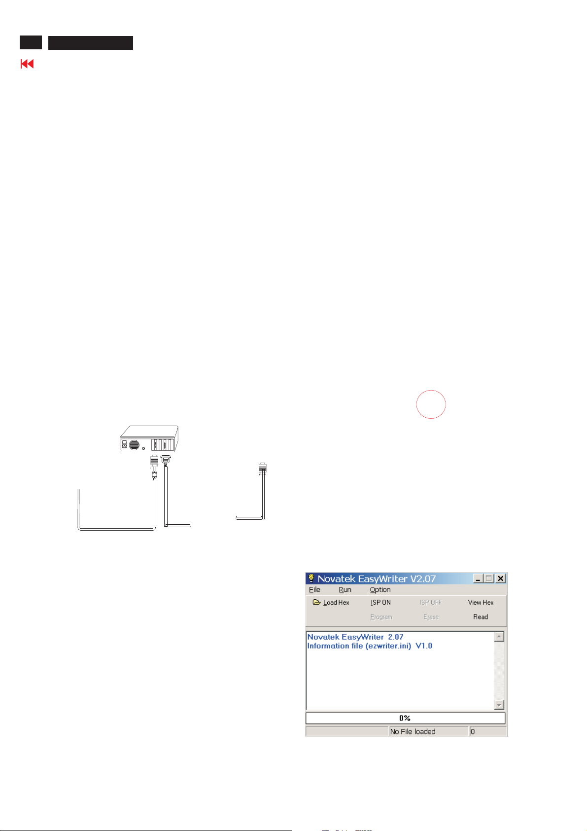
Update the firmware
1.Doubleclick the Easywriter.exeiconindesktop then appears
window as showninFig.6 .
Fig. 5
Step1:Makeafolder in your PC as showninFig. 3.
Step 2 : Copy ISP Software Easywriter into your folder
For example : C:\
as showni
nFig.3.
170S5
26MF605W-17
Fig. 3
Fig. 6
 Loading...