

Page 1
PHILIPS 22PFS5303, PHILIP S 2 4PFS5703 LCD TV - HOW TO UPGRADE
THE SOFTWARE , ERR O R CO DE S DI AG NOSING, SERV I CE M O DE,
POWER SUPPL Y A ND A U DIO OUTPUT SCHEM AT I C DI AG R A M
22PFS5303-12, 22PFS5403-12, 22PFT5303-05,
22PFT5303-12, 24PFS530 3-12, 24PFS5703-12 - Platform: NT72461. Chassis
name: TPN18.1E LA
Always respect voltages. While some may not be dangerous in themselves, they
can cause unexpected reactions that are best avoided. Before reaching into a
powered TV set, it is best to test the high voltage insulation. It is easy to do, and is a
good service precaution.
BOM identification
It should be noted that on the European Service website, “Alternative BOM” is
referred to as “Design variant”.
The third digit in the serial number (example: AG2B0335000001) indicates the
number of the alternative B.O.M. (Bill Of Materials) that has been used for producing
the specific TV set. In general, it is possible that the same TV model on the market is
produced with e.g. two different types of displays, coming from two different
suppliers. This will then result in sets which have the same CTN (Commercial Type
Number; e.g. 28PW9515/12) but which have a different B.O.M. number.
By looking at the third digit of the serial number, one can identify which B.O.M. is
used for the TV set he is working with. If the third digit of the serial number contains
the number “1” (example: AG1B033500001), then the TV set has been manufactured
according to B.O.M. number 1. If the third digit is a “2” (example: AG2B0335000001),
then the set has been produced according to B.O.M. no. 2. This is important for
ordering the correct spare parts.
For the third digit, the numbers 1...9 and the characters A...Z can be used, so in total:
9 plus 26= 35 different B.O.M.s can be indicated by the third digit of the serial
number.
Identification: The bottom line of a type plate gives a 14-digit serial number. Digits 1
and 2 refer to the production centre (e.g. SN is Lysomice, RJ is Kobierzyce), digit 3
refers to the B.O.M. code, digit 4 refers to the Service version change code, digits 5
and 6 refer to the production year, and digits 7 and 8 refer to production week (in
Page 2
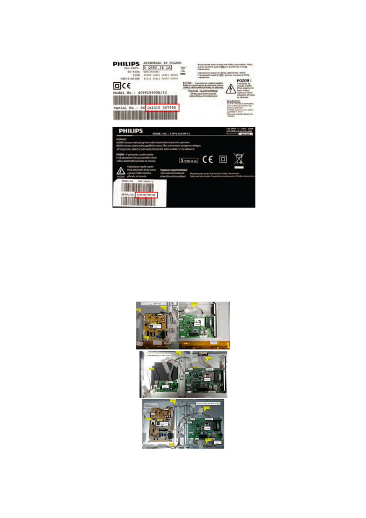
example below it is 2010 week 10 / 2010 week 17). The 6 last digits contain the serial
number.
Board Level Repair (BLR) or Component Level
Repair (CLR)
If a board is defective, consult your repair procedure to decide if the board has to be
exchanged or if it should be repaired on component level.
If your repair procedure says the board should be exchanged completely, do not
solder on the defective board.
Otherwise, it cannot be returned to the O.E.M. supplier for back charging.
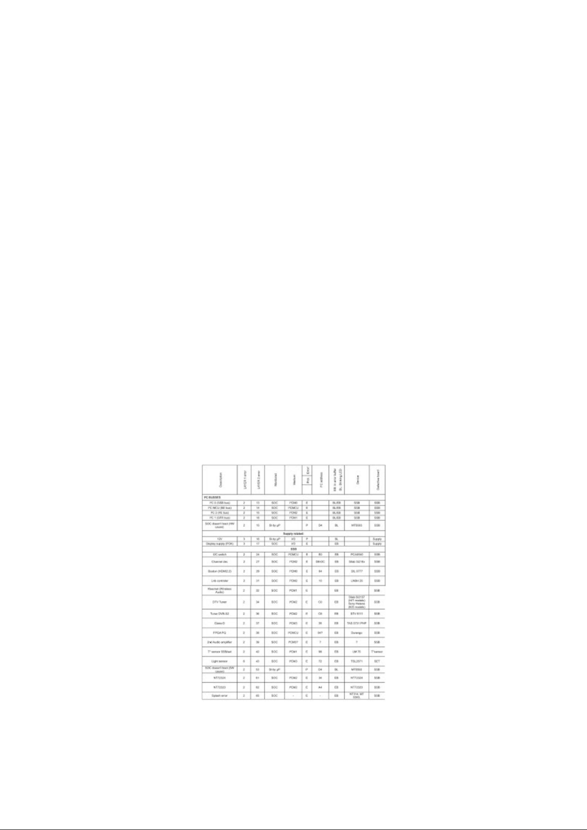
Cable dressing
Service Alignment Mode (SAM)
Page 3

To activate SAM, use one of the following methods:
Press the following key sequence on the remote control transmitter: “062596”,
directly followed by the “INFO/OK” button. Do not allow the display to time out
between entries while keying the sequence.
Or via ComPair.
After entering SAM, the following items are displayed, with “SAM” in the upper right
corner of the screen to indicate that the television is in Service Alignment Mode.
How to Navigate
In the SAM menu, select menu items with the UP/DOWN keys on the remote control
transmitter. The selected item will be indicated. When not all menu items fit on the
screen, use the UP/DOWN keys to display the next/previous menu items.
With the “LEFT/RIGHT” keys, it is possible to:
(De) activate the selected menu item.
(De) activate the selected sub menu.
Change the value of the selected menu item.
When you press the MENU button once while in top level SAM, the set will switch to
the normal user menu (with the SAM mode still active in the background).
How to Store SAM Settings
To store the settings changed in SAM mode (except the RGB Align settings), leave
the top level SAM menu by using the POWER button on the remote control
transmitter or the television set. The mentioned exceptions must be stored separately
via the STORE button.
How to Exit SAM
Use one of the following methods:
Switch the set to STANDBY by pressing the mains button on the remote control
transmitter or the television set.
Via a standard RC-transmitter, key in “00” sequence.
Note: When the TV is switched “off” by a power interrupt while in SAM, the TV will
show up in “normal operation mode” as soon as the power is supplied again. The
error buffer will not be cleared.
How to Activate the Factory mode
To activate the Factory mode, use the foll owing method:
Press the following key sequence on the remote control transmitter: from the
“menu/home” press “1999”, directly followed by the “Back/Return” button. Do not
allow the display to time out between entries while keying the sequence.
After entering the Factory mode, we can see many items displayed, use the
UP/DOWN keys to display the next/previous menu items.
How to Exit the Factory mode
Use one of the following methods:
Select EXIT_FACTORY from the menu and press the “OK” button.
Page 4

Note: When the TV is switched “off” by a power interrupt, or normal switch to “standby” while in the factory mode, the TV will show up in “normal operation mode” as
soon as the power is supplied again. The error buffer will not be cleared.
Software Upgrading, Error code and Panel Code
The following update is for .pkg file.
1. Rename the file to “upgrade_loader.pkg”.
2. Prepare a USB memory (File format: FLAT, Size: 1G~8G).
3. Copy the software to USB flash disk (root directory).
4. Switch off the TV and Insert the USB memory stick that contains the software
update files in one of the TV’s USB 2.0 port.
5. Switch on the TV. The TV will detect the USB memory stick automatically.
6. When the TV software is updated, the TV will turn on again automatically. Remove
your USB flash drive.
7. We can enter in CSM to check the current software version.
The following update is for .upg file.
Rename the file to “Autorun.upg”.
2. Prepare a USB memory (File format: FLAT, Size: 1G~8G).
3. Copy the software to USB flash disk (root director y).
Note the version of this F/W before you change the software file name.
F/W Upgrade
1. Plug the USB memory on the TV’s USB 2.0 port.
2. AC on (Power plug).
3. TV will show message as below image, Press [Start] to detect the software
automatically
4. Press [Start] to start software upgrade
5. Upgrade in progress.
6. After software upgrade complete, select [Restart] to reboot TV.
Check the SW version
1. After burning software, TV will restart.
2. Press “123654”, enter Customer Service Mode to check if the software version is
correct.
Caution: Please make sure that software upgrade is finished before unplug the USB
and AC power.
Error Code
Error codes are required to indicate failures in the TV set. In principle a unique error
code is available for ever y :
• Activated (SW) protection.
• Failing I2C device.
Page 5
• General I2C error.
The last five errors, stored in the NVM, are shown in the Service menu’s. This is
called the error buffer.
The error code buffer contains all errors detected since the last time the buffer was
erased. The buffer is written from left to right. When an error occurs that is not yet in
the error code buffer, it is displayed at the left side and all other errors shift one
position to the right.
An error will be added to the buffer if this error differs from any error in the buffer. The
last found error is displayed on the left.
An error with a designated error code never leads to a deadlock situation. It must
always be diagnosable (e.g. error buffer via OSD or blinking LED).
In case a failure identified by an error code automatically results in other error codes
(cause and effect), only the error code of the MAIN failure is displayed.
How to Read the Error Buffer
You can read the error buffer in below ways:
• On screen via the SAM/CSM (if you have a picture).
Example:
– ERROR: 000 000 000 000 000: No errors detected
– ERROR: 013 000 000 000 000: Error code 13 is the last and only detected error
– ERROR: 034 013 000 000 000: Error code 13 was detected first and error code 34
is the last detected (newest) error
• Via the blinking LED procedure (when you have no picture).
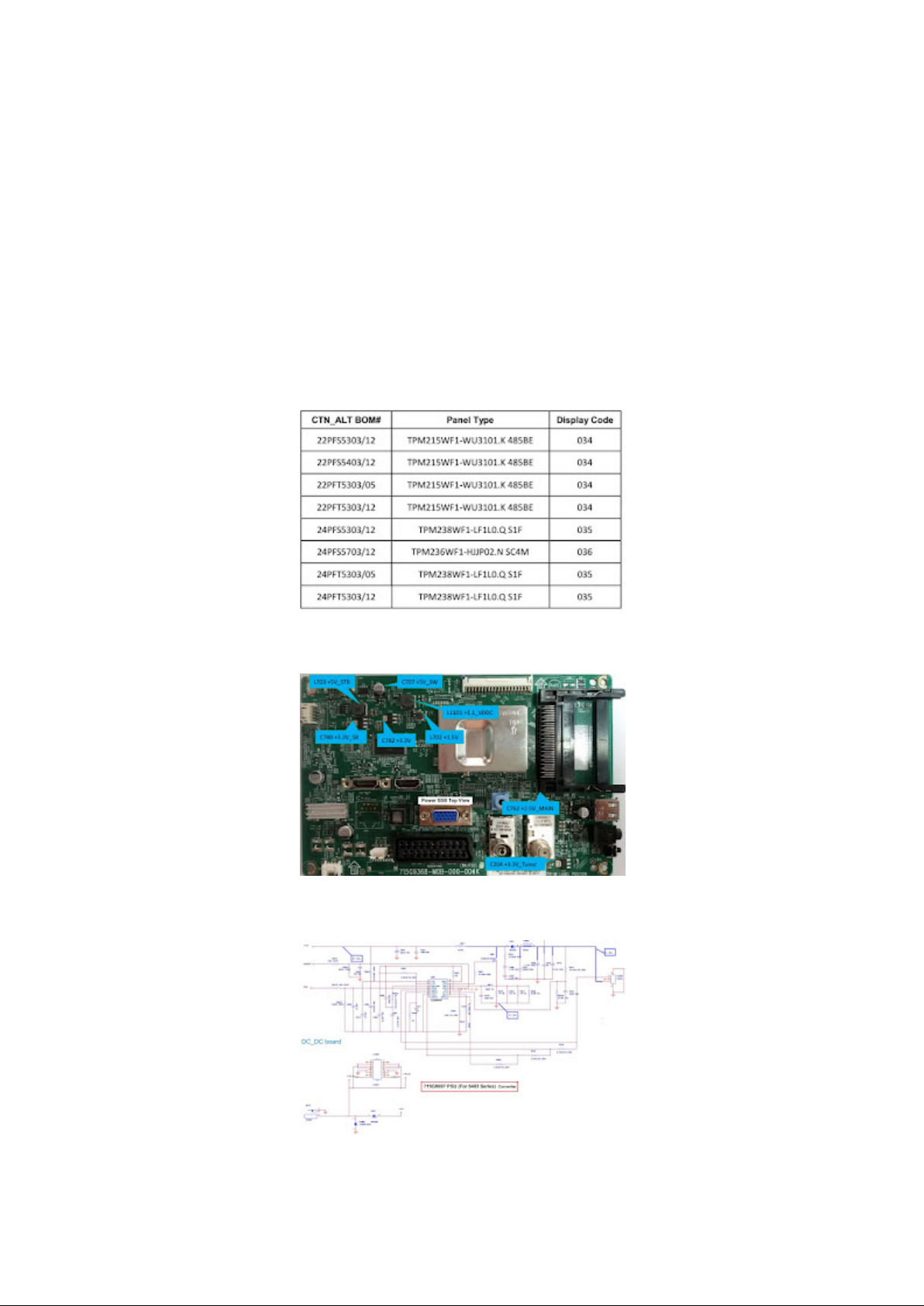
Error codes overview: In this chassis only “layer 2” error codes are available and
point to problems on the SSB. They are triggered by LED blinking when CSM is
activated. Only the following layer 2 errors are defined:
How to Clear the Error Buffer
The error code buffer is cleared in the following cases:
• By using the CLEAR command in the SAM menu
Page 6
• By using the CLEAR command in the Factory mode:
• By using the following key sequence on the remote control transmitter: “062599”
directly followed by the OK button.
• If the contents of the error buffer have not changed for 50 hours, the error buffer
resets automatically.
Note: If you exit SAM by disconnecting the mains from the television set, the error
buffer is not reset.
Panel Code
Press the following key sequence on a standard RC transmitter: “062598” directly
followed by MENU and “xxx”, where “xxx” is a 3 digit decimal value of the panel type:
see column “Display Code” in below tab. After resetting the Display Code, restart the
set immediately.
Power layout SSB
Power supply schematic
Page 7

715G9368 SSB System POWER
Page 8
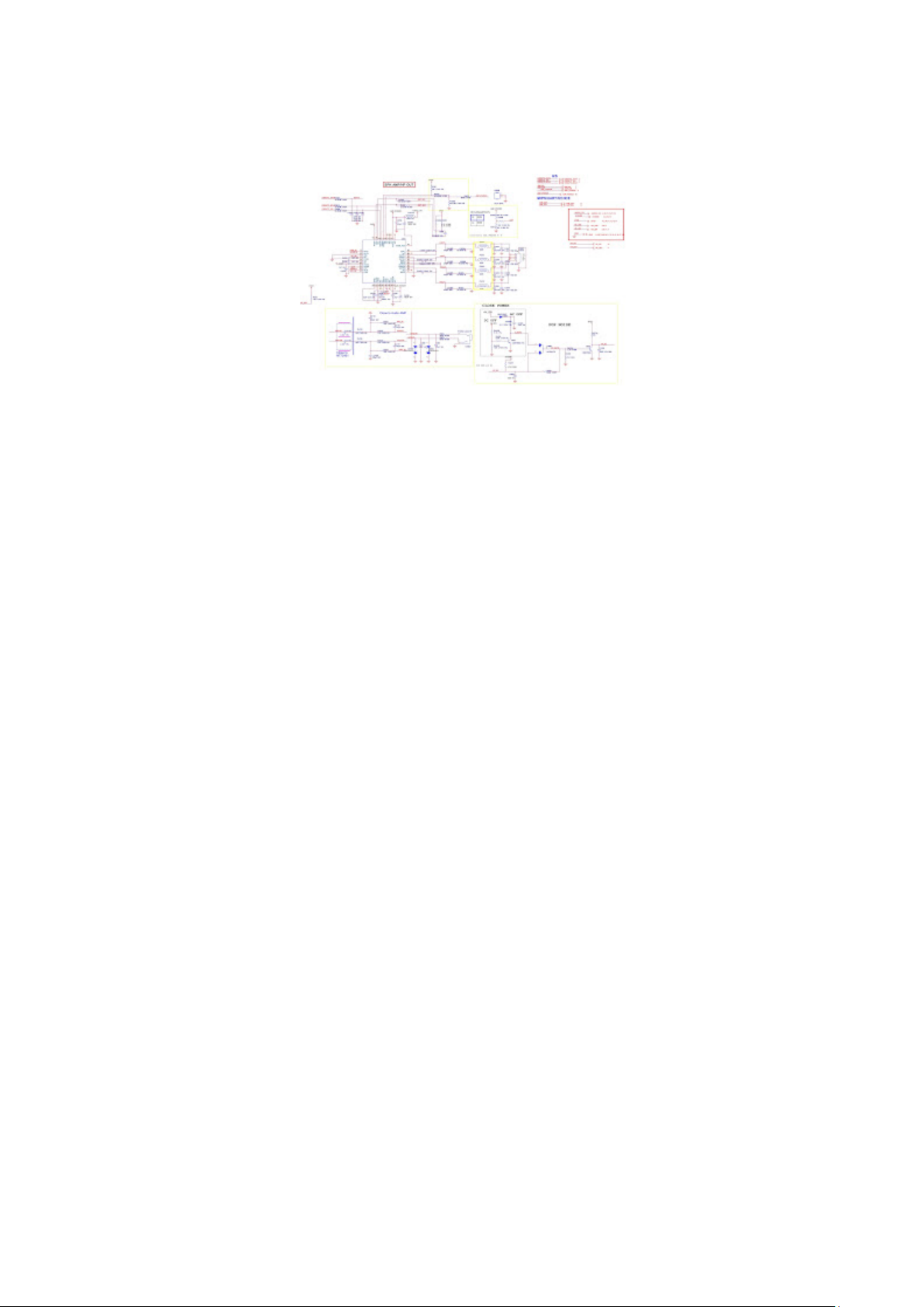
Audio output schematic
 Loading...