

Page 1

Philips Consumer Electronics
Technical Service Data
Service and Quality
Service Publications Dept.
One Philips Drive
P.O. Box 14810
Knoxville, TN 37914
Manual 7602
Model no.: 20LW202222
First Publish: 5-10-2001
Rev. Date: 10-16-2002
Print Date: 19/11/2005
Electrical Adjustments
REFER TO SAFETY GUIDELINES
SAFETY NOTICE: ANY PERSON ATTEMPTING TO SERVICE THIS CHASSIS MUST FAMILIARIZE
HIMSELF WITH THE CHASSIS AND BE AWARE OF THE NECESSARY SAFETY PRECAUTIONS
TO BE USED WHEN SERVICING ELECTRONIC EQUIPMENT CONTAINING HIGH VOLTAGES.
CAUTION: USE A SEPARATE ISOLATION TRANSFORMER FOR THIS UNIT WHEN SERVICING
© Philips Electronics North America Corporation Visit our World Wide Web Site at http://www.forceonline.com
Page 2

Alignments
Note:
Codes And Fault Finding. Menu navigation is done with the 'CURSOR UP, DOWN, LEFT or RIGHT' keys of the
remote control transmitter.
The Service Default Mode (SDM) and Service Alignment Mode (SAM) are described in Service Modes Error
General Alignment Conditions
Perform all electrical adjustments under the following conditions:
• AC voltage and frequency: 110 V (± 10 %), 60 Hz (± 5 %).
• Connect the set to the AC power via an isolation transformer.
• Allow the set to warm up for approximately 20 minutes.
• Measure the voltages and waveforms in relation to chassis ground (with the exception of the voltages on the
primary side of the power supply). Never use the cooling fins / plates as ground.
• Test probe: Ri > 10 MΩ; Ci < 2.5 pF.
• Use an isolated trimmer / screwdriver to perform the alignments.
Hardware Alignments
Page 3
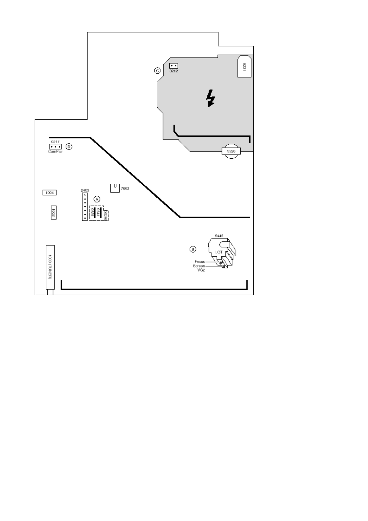
Fig. 1
Vg2 Adjustment
1. Activate the SAM.
2. Go to the WHITE TONE sub menu.
3. Set the values of NORMAL RED, GREEN and BLUE to 40.
4. Go, via the MENU key, to the normal user menu and set
- CONTRAST to zero.
- BRIGHTNESS to minimum (OSD just visible in a dark room).
5. Return to the SAM via the MENU key.
6. Connect the RF output of a pattern generator to the antenna input. Test pattern is a 'black' picture (bl ank screen
on CRT without any OSD info).
Page 4
7. Set the channel of the oscilloscope to 50 V/div and the time base to 0.2 ms (external triggering on the vertical
pulse).
8. Ground the scope at the CRT panel and connect a 10:1 probe to one of the cathodes of the picture tube socket
(see diagram B).
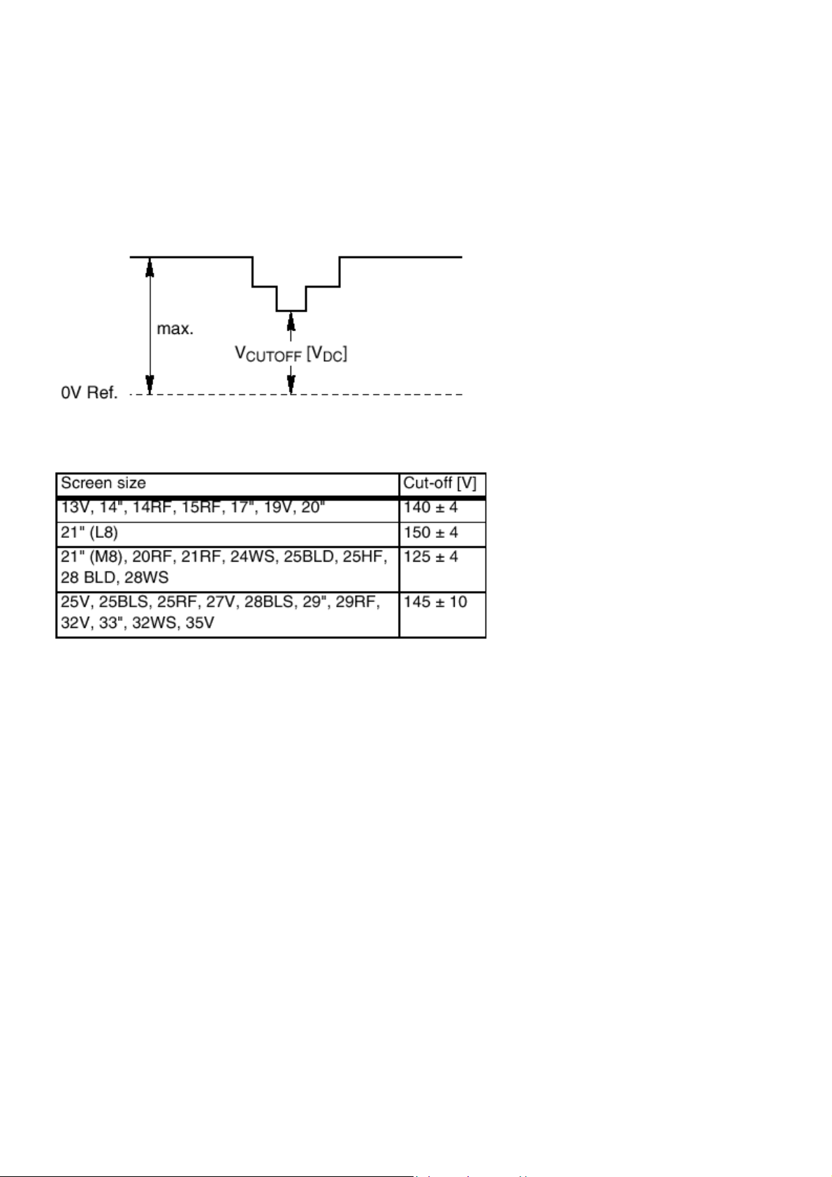
9. Measure the cut off pulse during first full li n e after the frame blanking (see Fig. 2). You will see two pulses, one
being the cut off pulse and the other being the white drive pulse. Choose the one with the lowest value, this is the
cut off pulse.
10. Select the cathode with the highest V
potentiometer (see Fig. 1) on the LOT to the correct value (see table below).
11. Restore BRIGHTNESS and CONTRAST to normal (= 31).
Fig. 2
DC value for the alignment. Adjust the Vcutoff of this gun with the SCREEN
Focusing
1. Tune the set to a circle or crosshatch test pattern (use an external video pattern generator).
2. Choose picture mode NATURAL (or MOVIES) with the 'SMART PICTURE' button on the remote control
transmitter.
3. Adjust the FOCUS potentiometer (see Fig.1) until the vertical lines at 2/3 from east and west, at the height of the
centerline, are of minimum width without visible haze.
Software Alignments And Settings
Enter the Service Alignment Mode (see Service Modes Error Codes And Fault Finding.). The SAM menu will now
appear on the screen.
Options
Page 5
A
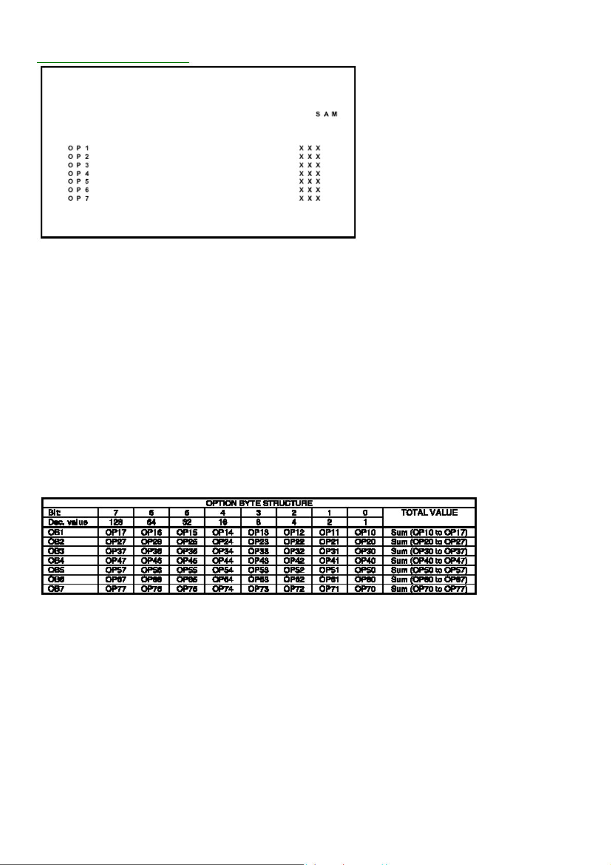
Display Option Byte Table
Options are used to control the presence / absence of certain
features and hardware.
How to change an Option Byte
n Option Byte represents a number of differen t op ti ons.
Changing these bytes directly makes it possible to set all options very fast. All options are controlled via seven option
bytes. Select the option byte (OB1.. OB7) with the MENU UP/DOWN keys, and enter the new value.
Leaving the OPTION submenu saves changes in the Option Byte settings. Some changes will only take effect after
the set has been switched OFF and ON with the AC power switch (cold start).
How to calculate the value of an Option Byte
Calculate an Option Byte value (OB1 .. OB7) in the following way:
1. Check the status of the single option bits (OP): are they enabled (1) or disabled (0).
2. When an option bit is enabled (1) it represents a certain value (see column 'Dec. value' in table below). When an
option bit is disabled, its value is 0.
3. The total value of an Option Byte is formed by the sum of its eight option bits.
Option Bit Assignment
Following are the option bit assignments for all L01 software
clusters.
• Option Byte 1 (OB1)
− OP10: CHINA
− OP11: VIRGIN_MODE
Page 6

− OP12: UK_PNP
− OP13: ACI
− OP14: ATS
− OP15: LNA
− OP16: FM_RADIO
− OP17: PHILIPS_TUNER
• Option Byte 2 (OB2)
− OP20: HUE
− OP21: COLOR_TEMP
− OP22: CONTRAST_PLUS
− OP23: TILT
− OP24: NOISE_REDUCTION
− OP25: CHANNEL_NAMING
− OP26: SMART_PICTURE
− OP27: SMART_SOUND
• Option Byte 3 (OB3)
− OP30: AVL
− OP31: WSSB
− OP32: WIDE_SCREEN
− OP33: SHIFT_HEADER_SUBTITLE
− OP34: CONTINUOUS_ZOOM
− OP35: COMPRESS_16_9
− OP36: EXPAND_4_3
− OP37: EW_FUNCTION
• Option Byte 4 (OB4)
− OP40: STEREO_NON_DBX
− OP41: STEREO_DBX
− OP42: STEREO_PB
− OP43: STEREO_NICAM_2CS
− OP44: DELTA_VOLUME
− OP45: ULTRA_BASS
− OP46: VOLUME_LIMITER
− OP47: INCR_SUR
• Option Byte 5 (OB5)
− OP50: PIP
− OP51: HOTEL_MODE
− OP52: SVHS
− OP53: CVI
− OP54: AV3
− OP55: AV2
− OP56: AV1
− OP57: NTSC_PLAYBACK
• Option Byte 6 (OB6)
− OP60: Reserved (value = 0)
− OP61: SMART_TEXT
− OP62: SMART_LOCK
− OP63: VCHIP
− OP64: WAKEUP_CLOCK
− OP65: SMART_CLOCK
Page 7

− OP66: SMART_SURF
− OP67: PERSONAL_ZAPPING
• Option Byte 7 (OB7)
− OP70: SOUND_SYSTEM_AP_3 /MULTI_STANDARD_EUR / SYSTEM_LT_2
− OP71: SOUND_SYSTEM_AP_2 / WEST_EU/ SYSTEM_LT_1
− OP72: SOUND_SYSTEM_AP_1
− OP73: COLOR_SYSTEM_AP
− OP74: Reserved (value = 0)
− OP75: Reserved (value = 0)
− OP76: TIME_WIN2
− OP77: TIME_WIN1
Option bit definition
• OP10: CHINA
0 : Tuning is not for China set, or this option bit is not applicable,
1 : Tuning is for China set,
Default setting : 0.
• OP11: VIRGIN_MODE 0 :
Virgin mode is disabled or not applicable,
1 : Virgin mode is enabled. Plug and Play menu item will be displayed to perform installation at the initial startup of
the TV when VIRGIN_MODE is set to 1. After installation is finished, this option bit will be automatically set to 0,
Default setting : 0.
• OP12: UK_PNP
0 : UK's default Plug and Play setting is not available or not applicable, 1 : UK's default Plug and Play setting is
available. When UK_PNP and VIRGIN_MODE are set to 1 at the initial setup, LANGUAGE = ENGLISH,
COUNTRY = GREAT BRITAIN and after exiting from menu, VIRGIN_MODE will be set automatically to 0 while
UK_PNP remains 1,
Default setting : 0.
• OP13: ACI
0 : ACI feature is disabled or not applicable,
1 : ACI feature is enabled,
Default setting : 0.
• OP14: ATS
0 : ATS feature is disabled or not applicable, 1 : ATS feature is enabled. Wh en ATS is enabled, it sorts the
program in an ascending order starting from program 1,
Default setting : 0.
• OP15: LNA
0 :Auto Picture Booster is not available or not applicable,
1: Auto Picture Booster is available,
Default setting : 0.
• OP16: FM_RADIO
0 : FM radio feature is disabled or not applicabl e ,
1 : FM radio feature is enabled,
Default setting : 0.
• OP17: PHILIPS_TUNER
0 : ALPS / MASCO compatible tuner is in use,
1 : Philips compatible tuner is in use,
Default setting : 0.
• OP20: HUE
Page 8

0 : Hue/Tint Level is disabled or not applicable,
1 : Hue/Tint Level is enabled,
Default setting : 0.
• OP21: COLOR_TEMP
0 : Color Temperature is disabled or not applicabl e ,
1 : Color Temperature is enabled,
Default setting : 0.
• OP22: CONTRAST_PLUS
0 : Contrast+ is disabled or not applicable,
1 : Contrast+ is enabled,
Default setting : 0.
• OP23: TILT
0 : Rotate Picture is disabled or not applicable,
1 : Rotate Picture is enabled,
Default setting : 0.
• OP24: NOISE_REDUCTION
0 : Noise Reduction (NR) is disabled or not applicable,
1 : Noise Reduction (NR) is enabled,
Default setting : 0.
• OP25: CHANNEL_NAMING
0 : Name FM Channel is disabled or not applicable,
1 : Name FM Channel is enabled,
Default setting : 0.
Note : Name FM channel can be enabled only when FM_RADIO = 1.
• OP26: SMART_PICTURE
0 : Smart Picture is disabled or not applicable,
1 : Smart Picture is enabled,
Default setting : 1
• OP27: SMART_SOUND
0 : Smart Sound is disabled or not applicable,
1 : Smart Sound is enabled,
Default setting : 1
• AP30: AVL
0 : AVL is disabled or not applicable,
1 : AVL is enabled,
Default setting : 0.
• OP31: WSSB
0 : WSSB is disabled or not applicable,
1 : WSSB is enabled,
Default setting : 0.
Note : This option bit can be set to 1 only when WIDE_SCREEN = 1.
• OP32: WIDE_SCREEN
0 : Software is used for 4:3 set or not applicable,
1 : Software is used for 16:9 set,
Default setting : 0.
• OP33: SHIFT_HEADER_SUBTITLE
0 : Shift Header / Subtitle is disabled or not applicable,
1 : Shift Header / Subtitle is enabled,
Default setting : 0.
Note : This option bit can be set to 1 only when WIDE_SCREEN = 1.
Page 9

• OP34: CONTINUOUS_ZOOM
0 : Continuous Zoom is disabled or not applicable,
1 : Continuous Zoom is enabled,
Default setting : 0.
Note : This option bit can be set to 1 only when WIDE_SCREEN = 1.
• OP35: COMPRESS_16_9
0 : COMPRESS 16:9 selection is not applicable. Item should not be in the FORMAT menu list,
1 : COMPRESS 16:9 selection is applicable. Item should not be in the FORMAT menu list,
Default setting : 0.
• OP36: EXPAND_4_3
0 : Expand 4:3 selection is not applicable. Item should not be in the FORMAT menu list,
1 : Expand 4:3 selection is applicable. Item should be in the FORMAT menu list,
Default setting : 0.
• OP37: EW_FUNCTION
0 : EW function is disabled. In this case, only Expand 4:3 is allowed, Compress 16:9 is not applicable.
1 : EW function is enabled. In this case, both Expand 4:3 and Compress 16:9 are applicable.
Default setting : 0.
• OP40: STEREO_NON_DBX
0 : For AP_NTSC, chip TDA 9853 is not present,
1 : For AP_NTSC, chip TDA 9853 is present,
Default setting : 0.
• OP41: STEREO_DBX
0 : For AP_NTSC, chip MSP 3445 is not present,
1 : For AP_NTSC, chip MSP 3445 is present, Default setting : 0.
• OP42: STEREO_PB
0 : For AP_PAL, chip MSP3465 is not present,
1 : For AP_PAL, chip MSP3465 is present,
Default setting : 0.
• OP43: STEREO_NICAM_2CS
0 : For EU and AP_PAL, chip MSP 3415 is not present,
1 : For EU and AP_PAL, chip MSP 3415 is present,
Default setting : 0.
• OP44: DELTA_VOLUME
0 : Delta Volume Level is disabled or not applic a bl e ,
1 : Delta Volume Level is enabled,
Default setting : 0.
• OP45: ULTRA_BASS
0 : Ultra Bass is disabled or not applicable,
1 : Ultra Bass is enabled,
Default setting : 0.
• OP46: VOLUME_LIMITER
0 : Volume Limiter Level is disabled or not applicable,
1 : Volume Limiter Level is enabled,
Default setting : 0.
• OP47: INCR_SUR
0 : Incredible Surround feature is disabled,
1 : Incredible Surround feature is enabled,
Default setting : 1
• OP50: PIP
0 : PIP is disabled or not applicable,
Page 10

1 : PIP is enabled,
Default setting : 0.
• OP51: HOTEL_MODE
0 : Hotel mode is disabled or not applicable,
1 : Hotel mode is enabled,
Default setting : 0.
• OP52: SVHS
0 : SVHS source is not available,
1 : SVHS source is available,
Default setting : 0.
Note : This option bit is not applicable for EU.
• OP53: CVI
0 : CVI source is not available,
1 : CVI source is available,
Default setting : 0.
• OP54: AV3
0 : Side/Front AV3 source is not present,
1 : Side/Front AV3 source is present,
Default setting : 0.
• OP55: AV2
0 : AV2 source is not present,
1 : AV2 source is present,
Default setting : 0.
Note : For EU, when AV2=1, both EXT2 and SVHS2 should be included in the OSD loop.
• OP56: AV1
0 : AV1 source is not present,
1 : AV1 source is present,
Default setting : 0.
• OP57: NTSC_PLAYBACK
0 : NTSC playback feature is not available,
1 : NTSC playback feature is available,
Default setting : 0.
• OP60: Reserved
Default setting : 0.
• OP61: SMART_TEXT
0 : Smart Text Mode and Favorite Page are disabled or not applicable,
1 : Smart Text Mode and Favorite Page are enabled,
Default setting : 1.
• OP62: SMART_LOCK
0 : Child Lock and Lock Channel are disabled or not applicable for EU,
1 : Child Lock and Lock Channel are enabled for EU,
Default setting : 1.
• OP63: VCHIP
0 : VCHIP feature is disabled,
1 : VCHIP feature is enabled,
Default setting : 1.
• OP64: WAKEUP_CLOCK
0 : Wake up clock feature is disabled or not applicable,
1 : Wake up clock feature is enabled,
Default setting : 1.
Page 11

• OP65: SMART_CLOCK
0 : Smart Clock Using Teletext and Smart Clock Using PBS is disabled or not applicable,
1 : Smart Clock Using Teletext and Smart Clock Using PBS is enabled. For NAFTA, menu item AUTOCHRON is
present in the INSTALL submenu,
Default setting : 0.
• OP66: SMART_SURF
0 : Smart Surf feature is disabled or not applicable,
1 : Smart Surf feature is enabled,
Default setting : 0.
• OP67: PERSONAL_ZAPPING
0 : Personal Zapping feature is disabled or not applicable,
1 : Personal Zapping feature is enabled,
Default setting : 0.
• OP70: MULTI_STANDARD _EUR
0 : Not for Europe multi standard set, or this option bit is not applicable,
1 : For Europe multi standard set.
Default setting : 0.
Note : This option bit is used to control the SYSTEM selection in Manual Store : If MULTI_STANDARD_EUR = 1
then SYSTEM = Europe, West Europe, East Europe, UK, France otherwise SYSTEM = 'Europe, West Europe,
UK for West Europe' (WEST_EU=1) or SYSTEM = 'Europe, West Europe, East Europe for East Europe'
(WEST_EU=0)
• OP71: WEST_EU
0 : For East Europe set, or this option bit is not applicable,
1 : For West Europe set,
Default setting : 0.
• OP71 and 70: SYSTEM_LT_1, SYSTEM_LT_2
These two option bits are allocated for LATAM system selection.
00 : NTSC-M
01 : NTSC-M, PAL-M
10 : NTSC-M, PAL-M, PAL-N
11 : NTSC-M, PAL-M, PAL-N, PAL-BG
Default setting : 00
• OP70, 71 and 72: SOUND_SYSTEM_AP_1, SOUND_SYSTEM_AP_2, SOUND_SYSTEM_AP_3
These three option bits are allocated for AP_PAL sound system selection.
000 : BG
001 : BG / DK
010 : I / DK
011 : BG / I / DK
100 : BG / I / DK / M
Default setting : 00
• OP73: COLOR_SYSTEM_AP
This option bit is allocated for AP-PAL color system selection.
0 : Auto, PAL 4.43, NTSC 4.43, NTSC 3.58
1 : Auto, PAL 4.43, NTSC 4.43, NTSC 3.58, SECAM
Default setting : 0
• OP74: Reserved
Default setting : 0.
• OP75: Reserved
Default setting : 0.
Page 12
• OP77 and 76: TIME_WIN1, TI ME_WIN2
A
A
00 :The time window is set to 1.2s
01 : The time window is set to 2s
10 : The time window is set to 5s
11 : not in use
Default setting : 01
Note :The time-out for all digit entries depend on this setting.
Tuner
Note: Described alignments are only necessary when the NVM (item 7602) is replaced.
IF PLL
This adjustment is auto-aligned. Therefore, no action is
required.
FW (AFC window)
Fixed value is OFF.
GC (AGC take over point)
Set the external pattern generator to a color bar video signal and connect the RF output to aerial in put. Set amplitude
to 10 mV and set frequency to 61.25 MHz (channel 3).
Connect a DC multimeter to pin 1 of the tuner (item 1000 on the main panel).
1. Activate the SAM.
2. Go to the TUNER sub menu.
3. Select AFW with the UP/DOWN cursor keys and set to ON.
4. Select AGC with the UP/DOWN cursor keys.
5. Adjust the AGC-value (default value is 27) with the LEFT/RIGHT cursor keys until the voltage at pin 1 of the tuner
Page 13
lies between 3.8 and 2.3 V.
A
A
A
A
6. Select AFW with the UP/DOWN cursor keys and set to OFF.
7. Switch the set to STANDBY.
YD (Y-delay adjustment)
lways set to 3.
CL (Cathode drive level)
lways set to 4.
FA
Read only bit, for monitoring purpose only.
FB
Read only bit, for monitoring purpose only.
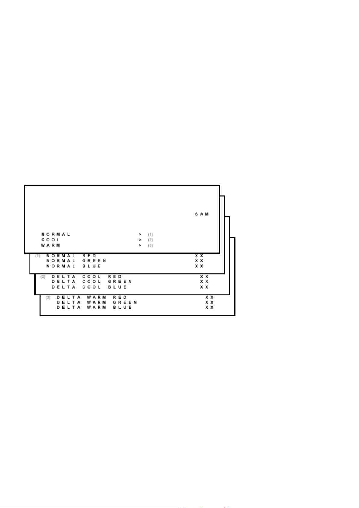
White Tone
In the WHITE TONE sub menu, the values of the black cut off level can be adjusted. Normally, no alignment is
needed for the WHITE TONE. You can use the given default values.
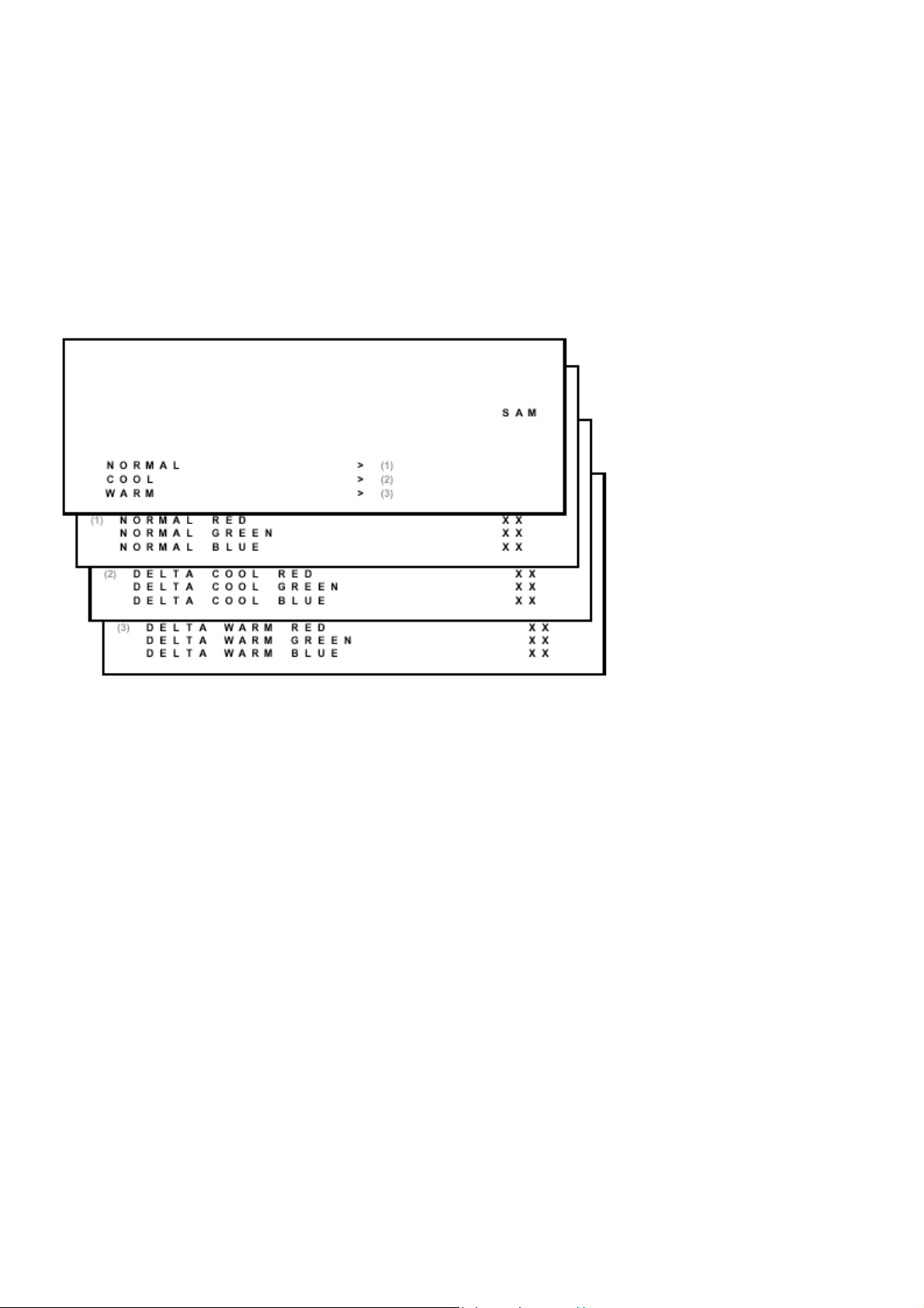
The color temperature mode (NORMAL, COOL and WARM) and the color (R, G, and B) can be selected with the
UP/DOWN RIGHT/LEFT cursor keys. The value can be changed with the LEFT/RIGHT cursor keys. First, select the
values for the NORMAL color temperature. Then select the values for the COOL and WARM mode. After alignment,
switch the set to standby, in order to store the alignments.
Default settings:
1. NORMAL (color temperature = 10500 K):
− NORMAL R = 40
− NORMAL G = 40
− NORMAL B = 40
Page 14

2. COOL (color temperature = 14000 K):
− DELTA COOL R = -2
− DELTA COOL G = 0
− DELTA COOL B = 6
3. WARM (color temperature = 8200 K):
− DELTA WARM R = 2
− DELTA WARM G = 0
− DELTA WARM B = -7
Geometry
The geometry alignments menu contains several items to align the set, in order to obtain a correct picture geometry.
Connect an external video pattern generator to the aerial input of the TV-set and input a crosshatch test pattern. Set
the generator amplitude to at least 1 mV and set frequency to 61.25 MHz (channel 3).
1. Set 'Smart Picture' to NATURAL (or MOVIES).
2. Activate the SAM menu (see chapter 5).
3. Go to the GEOMETRY sub menu.
4. Choose HORIZONT AL or VERTICAL alignment
Now the following alignments can be performed:
Horizontal:
• Horizontal Parallelogram (HP) Align straight vertical lines in the top and the bottom; vertical rotation around the
center.
• Horizontal Bow (HB) Align straight horizontal lines in the top and the bottom; horizontal rotation around the
center.
Page 15

• Horizontal Shift (HSH) Align the horizontal center of the picture to the horiz ontal center of the CRT.
• East West Width (EWW) Align the picture width until the complete test pattern is visible.
• East West Parabola (EWP) Align straight vertical lines at the sides of the screen.
• Upper Corner Parabola (UCP) Align straight vertical lines in the upper corners of the screen.
• Lower Corner Parabola (LCP) Align straight vertical lines in the lower corners of the screen.
• East West Trapezium (EWT) Align straight vertical lines in the middle of the screen.
• H60 Align straight horizontal lines if NTSC system is used (60 Hz) i.s.o. PAL (50 Hz).
Vertical:
• Vertical slope (VSL) Align the vertical center of the picture to the vertical center of the CRT. This is the first of the
vertical alignments to perform. For an easy alignment, set SBL to ON.
• Vertical Amplitude (VAM) Align the vertical amplitude so that the complete test pattern is visible.
• Vertical S-Correction (VSC) Align the vertical linearity, meaning that vertical intervals of a grid pattern must be
equal over the entire screen height.
• Vertical Shift (VSH) Align the vertical centering so that the test pattern is located vertically in the middle. Rep eat
the 'vertical amplitude' alignment if necessary.
• Vertical Zoom (VX) The vertical zoom is added in for the purpose of development. It helps the designer to set a
proper values for the movie expand or movie(16x9) compress. Default value is 25.
• V60 Align straight vertical lines if NTSC system (60 Hz) is used i.s.o. PAL (50 Hz).
• Service blanking (SBL) Switch the blanking of the lower half of the screen ON or OFF (to be used in combination
with the vertical slope alignment).
In the table below, you will find the GEOMETRY default values for the different sets.
Page 16
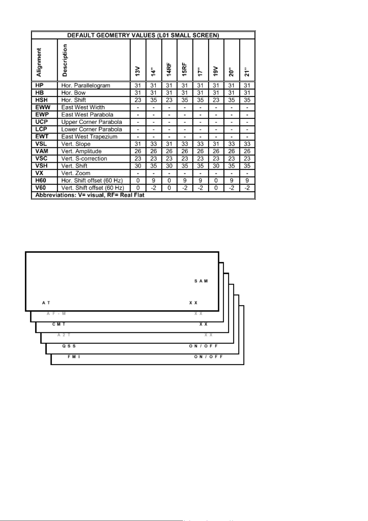
AT
Audio
No alignments are needed for the audio sub menu. Use the
given default values.
Default value is 8.
Page 17

CMT
Default value is 42.
QSS
OFF for mono sets, ON for stereo sets.
FMI
OFF for mono sets, ON for stereo sets.
Page 18

Philips Consumer Electronics
Technical Service Data
Service and Quality
Service Publications Dept.
One Philips Drive
P.O. Box 14810
Knoxville, TN 37914
Manual 7602
Model no.: 20LW202222
First Publish: 5-10-2001
Rev. Date: 10-16-2002
Print Date: 19/11/2005
Troubleshooting
REFER TO SAFETY GUIDELINES
SAFETY NOTICE: ANY PERSON ATTEMPTING TO SERVICE THIS CHASSIS MUST FAMILIARIZE
HIMSELF WITH THE CHASSIS AND BE AWARE OF THE NECESSARY SAFETY PRECAUTIONS
TO BE USED WHEN SERVICING ELECTRONIC EQUIPMENT CONTAINING HIGH VOLTAGES.
CAUTION: USE A SEPARATE ISOLATION TRANSFORMER FOR THIS UNIT WHEN SERVICING
© Philips Electronics North America Corporation Visit our World Wide Web Site at http://www.forceonline.com
Page 19

Service Modes, Error Codes And Fault Finding
A
Test Points
The chassis is equipped with test points printed on the circuit board assemblies. These test points refer to the
functional blocks:
Test point Circuit Diagram
A1-A2-A3-.. Audio processing A8, A9 / A11
C1-C2-C3-.. Control A7
F1-F2-F3-.. Frame drive and output A3
I1-I2-I3-.. Tuner & IF A4
L1-L2-L3-.. Line drive and output A2
P1-P2-P3-.. Power supply A1
S1-S2-S3-.. Synchronization A6
V1-V2-V3-.. Video processing A5, B1
The numbering is in a logical sequence for diagnostics.
lways start diagnosing within a functional block in the sequence of the relevant test points for that block.
Perform measurements under the following conditions:
• Service Default Mode.
• Video: color bar signal.
• Audio: 3 kHz left, 1 kHz right.
Service Modes
Service Default Mode (SDM) and Service Alignment Mode (SAM) offer several features for the service technician,
while the Customer Service Mode (CSM) is used for communication between dealer and customer.
Note: Some L8 and M8 chassis sets use a software version that does not contain the Service Modes (see table). In
this case, use the special Factory Mode Remote Control. This can be ordered by service code 4835 310 57511.
Complete instructions are included. This remote control will place the TV in the Factory Mode and allow access to all
adjustments that a normal Service Mode contains (including setting Option Bytes). Error codes will not be available.
There is also the option of using ComPair, a hardware interface between a computer (see requirements) and the TV
chassis. It offers the ability of structured trouble shooting, error code reading and software version readout for all L8
and M8 chassis.
Requirements: To run ComPair on a computer (laptop or desktop) requires, as a minimum, a 486 processor,
Windows 3.1 and a CD-ROM drive. A Pentium Processor and Windows 95/98 are also acceptable (see also
ComPair).
SW.
cluster
1US0 L01UN0-x.y TDA9587 Stereo, All Servioce
Softwar
name
UOC type Diversity Remark
Page 20

1US0 L01UN0-x.y TDA9587 Stereo,
non-DBX,
CC
1US1 L01US1-x.y TDA9587/
TDA9588
2US0 L01UM0-x.y TDA9587 Mono, CC All Service
2US1 L01UM1-x.y TDA9587 Mono, CC Without
3US0 L01US0-x.y TDA9588 Stereo,-DBXCCOnly
3US1 L01UN1-x.y TDA9587 Stereo,
Abbreviations in “Software Name”: U=USA, N=Stereo non-DBX, S=Stereo
DBX, M=Mono
Stereo,-DBXCCOnly
non-DBX,
CC
All Servioce
Modes
Com-Pair (*)
Modes
CSM (*)
Con-Pair (*)
Without
CSM (*)
Service Default Mode (SDM)
Purpose
• To create a predefined setting to get the same measurement results as given in this manual.
• To override SW protections.
• To start the blinking LED pr ocedure.
Specifications
• Tuning frequency: 61.25 MHz (channel 3).
• Color system: NTSC.
• All picture settings at 50 % (brightness, color contrast, hue).
• Bass, treble and balance at 50 %; volume at 25 %.
• All service-unfriendly modes (if present) are disabled, like:
− (sleep) timer,
− child/parental lock,
− blue mute,
− hotel/hospitality mode
− auto switch-off (when no 'IDENT' video signal is received for 15 minutes),
− skip / blank of non-favorite presets / channels,
− auto store of personal presets,
− auto user menu time-out.
How to enter SDM
• Use a standard customer RC-transmitter and key in the code 062596 directly followed by the MENU button, or
• Short wires 9631 and 9641 on the mono carrier and switch the set ON apply AC power. Then press the power
button (remove short after start-up).
Caution: Entering SDM by shorten wires 9631 and 9641 will override the +8V-protection. Do this only for a short
period. When doing this, the service-technician must know exactly what he is doing, as it could lead to damaging
Page 21

A
fter entering SDM, the following screen is visible, with SDM at the upper right side for recognition.
Page 22

How to navigate
• When you press the MENU button on the remote control, the set will switch between the SDM and the normal user
menu (with the SDM mode still active in the background). Return to the SDM screen with the OSD / STATUS
button.
• When you press the OSD / STATUS button on the remote control, the menu will show or hide the error buffer.
This feature is available to prevent interference during waveform measurements.
• On the TV press and hold the 'VOLUME down' and press the 'CHANNEL down' for a few from SDM to SAM and
reverse.
How to exit
Switch the set to STANDBY by pressing the power button on the remote control transmitter (if you switch the set OFF
by removing the AC power, the set will return in SDM when AC power is re-applied). The error buffer is cleared.
Service Alignment Mode (SAM)
Purpose
• To perform alignments.
• To change option settings.
• To display / clear the error code buffer.
Specifications
• Operation hours counter.
• Software version.
• Option settings.
• Error buffer reading and erasing.
• Software alignments.
Page 23

How to enter
• Use a standard customer RC-transmitter and key in the code 062596 directly followed by the OSD / STATUS
button or
• Via ComPair.
The following screen is visible, with SAM at the upper right side for recognition.
1. LLLL This is the operation hours counter. It counts the normal operation hours, not the standby hours.
2. AAABCD-X.Y This is the software identification of the main micro controller
• A = the project name (L01).
• B = the region: E = Europe, A = Asia Pacific, U = NAFTA, L = LATAM.
• C = the software diversity: N = stereo non-DBX, S = stereo DBX, M = mono, D = DVD.
• D = the language cluster number.
• E = UOC diversity.
• X = the main software version number.
• Y = the sub software version number.
3. SAM Indication of the actual mode.
4. Errors buffer Five errors possible.
5. Option bytes Seven codes possible.
6. Clear Erase the contents of the error buffer. Select the CLEAR menu item and press the CURSOR RIGHT key.
The content of the error buffer is cleared.
7. Options To set the Opti on Bytes. See chapter 8.3.1 for a detailed de scription.
8. AKB Disable (0) or enable (1) the 'black current loop' (AKB = Auto Kine Bias).
9. Tuner To align the Tuner. See chapter 8.3.2 for a detailed description.
10. White Tone To align the White Tone. See White tone for a detailed description.
11. Geometry To align the set geometry. See Geometry for a detailed description.
12. Audio No audio alignment is used for NTSC.
How to navigate
• In SAM, select menu items with the CURSOR UP/DOWN key on the remote control transmitter. The selected item
will be highlighted. When not all menu items fit on the screen, move the CURSOR UP/DOWN key to display the
next / previous menu items.
Page 24

• With the CURSOR LEFT/RIGHT keys, it is possible to:
A
− (De)activate the selected menu item.
− Change the value of the selected menu item.
− Activate the selected submenu.
• When you press the MENU button twice, the set will switch to the normal user menus (with the SAM mode still
active in the background). To return to the SAM menu press the OSD / STATUS button [ i+ ].
• When you press the MENU key in a submenu, you will return to the previous menu.
How to exit
Switch the set to STANDBY by pressing the power button on the remote control transmitter (if you switch the set OFF
by removing the AC power, the set will return in SAM when AC power is re-applied). The error buffer is not cleared.
Customer Service Mode (CSM)
Purpose
The Customer Service Mode is (de-)activated by the customer upon request of the service technician during a
telephone conversation, in order to identify the status of the set. This CSM is a read only mode, therefore
modifications in this mode are not possible.
How to enter
The CSM will be turned on after pressing the MUTE key on the remote control transmitter and any of the control
buttons on the TV for at least 4 seconds simultaneously. This activation only works if there is no menu on the screen.
fter switching ON the Customer Service Mode, the following screen will appear:
1. Software identification of the main micro controller (see Service Alignment Mode for an explanation).
2. Error code buffer (see for more details). Displays the last seven errors of the error code buffer.
3. In this line, the Option Bytes (OB) are visible. Each Option Byte is displayed as a decim al number between 0 and
255. The set may not work correctly when an incorrect option code is set. See Options for more information on the
option settings.
4. Indicates which color and sound system is installed for the selected pre-set.
5. Indicates if the set is not receiving an 'IDENT' signal on the selected source. It will display 'Not Tuned'.
Page 25

6. Indicates if the sleep timer is enabled.
A
7. Indicates if the V-chip feature is enabled.
8. Value indicates parameter levels at CSM entry.
CO = CONTRAST, CL = COLOR, BR = BRIGHTNESS,
HU = HUE, SH = SHARPNESS
9. Value indicates parameter levels at CSM entry.
VL = VOLUME LEVEL, BL = BALANCE LEVEL, AVL LIM
= AUTO VOLUME LEVEL LIMITER
10. Value indicates parameter levels at CSM entry.
DV = DELTA VOLUME, BS = BASS LEVEL, TR = TREBLE LEVEL
How to exit
You can turn the Customer Service Mode off:
• After you press 'any' key of the remote control transmitter with exception of the CHANNEL and VOLUME keys.
• After you switch-off the TV set with the AC power switch.
Problems And Solving Tips (Related To CSM)
Picture Problems
No colors / noise in picture
Check CSM line 4. Wrong color system installed. To change the setting:
1. Select the MANUAL STORE sub menu.
2. Select and change the SYSTEM setting until picture and sound are correct.
3. Select the STORE menu item.
Colors not correct / unstable picture
Check CSM line 4. Wrong color system installed. To change the setting:
1. Press the MENU button on the remote control.
2. Select the INST ALL sub menu.
3. Select the MANUAL STORE sub menu.
4. Select and change the SYSTEM setting until picture and sound are correct.
5. Select the STORE menu item .
TV switches off or changes channel without any user action
The TV set switches off after TV SWITCHING OFF was displayed.
uto standby switched the set off because:
• There was no 'ident' signal for more than 15 minutes or
• There was no remote control signal received or local key pressed for > 2 hours.
See Alignmentsfor a description of the options to enable / disable auto standby
Picture too dark or too bright
Increase / decrease the BRIGHTNESS and / or the CONTRAST value when:
• The picture improves after you have pressed the 'Smart Picture' button on the remote control.
• The picture improves afte r you have switched on the Customer Service Mode
The new 'Personal' preference value is automatically stored.
White line around picture elements and text
Page 26

Decrease the SHARPNESS value when:
• The picture improves after you have pressed the 'Smart Picture' button on the remote control.
• The picture improves afte r you have switched on the Customer Service Mode
The new 'Personal' preference value is automatically stored.
Snowy picture
Check CSM line 5. If this line indicates 'Not Tuned', check the following:
• No or bad antenna signal. Connect a proper antenna signal.
• Antenna not connected. Connect the antenna.
• No channel / preset is stored at this program number. Go to the INSTALL menu and store a proper channel at this
program number.
• The tuner is faulty (in this case the CODES line will contain error number 10). Check the tuner and replace / repair
if necessary.
Snowy picture and/or unstable picture
• A scrambled or decoded signal is received.
Black and white picture
Increase the COLOR value when:
• The picture improves after you have pressed the 'Smart Picture' button on the remote control.
• The picture improves afte r you have switched on the Customer Service Mode
The new 'Personal' preference value is automatically stored.
Menu text not sharp enough
Decrease the CONTRAST value when:
• The picture improves after you have pressed the 'Smart Picture' button on the remote control.
• The picture improves afte r you have switched on the Customer Service Mode
The new 'Personal' preference value is automatically stored.
Sound Problems
No sound or sound too loud (after channel change / switching on)
Increase / decrease the VOLUME level when the volume is OK after you switched on the CSM. The new 'Personal'
preference value is automatically sto r ed .
ComPair
Introduction
ComPair (Computer Aided Repair) is a service tool for Philips Consumer Electronics products. ComPair is a further
development on the European DST (service remote control), which allows faster and more accurate diagnostics.
Compare has three big advantages:
• ComPair helps you to quickly get an understanding on how to repair the chassis in a short time by guiding you
systematically through the repair procedures.
• ComPair allows very detailed diagnostics (on I
areas. You do not have to know anything about I
• ComPair speeds up the repair time since it can automatically communicate with the chassis (when the
2C level) and is therefore capable of accurately indicating problem
2 C commands yourself because ComPair takes care of this.
Page 27

microprocessor is working) and all repair information is directly available. When ComPair is installed together with
the SearchMan electronic manual of the defective chassis, schematics and PWBs are only a mouse click away.
Specifications
ComPair consists of a Windows based faultfinding program and an interface box between PC and the (defective)
product. The ComPair interface box is connected to the PC via a serial or RS232 cable.
In case of the L8/M8 chassis, the ComPair interface box and the TV communicate via a bi-directional service cable
via the service connector (located on the Main panel, see Hardware alignments
The ComPair faultfinding program is able to determine the problem of the defective television. ComPair can gather
diagnostic information in two ways:
1. Automatic (by comm un ic at ion with the television)
ComPair can automatically read out the contents of the entire error buffer. Diagnosis is done on I
ComPair can access the I 2 C bus of the television. ComPair can send and receive I 2 C commands to the micro
controller of the television. In this way, it is possible for ComPair to communicate (read and write) to devices on
2 C busses of the TV-set.
the I
2. Manually (by asking questions to you)
Automatic diagnosis is only possible if the micro controller of the television is working correctly and only to a
certain extend. When this is not the case, ComPair will guide you through the faultfinding tree by asking you
questions (e.g. Does the screen gives a picture? Click on the correct answer: YES / NO) and showing you
examples (e.g. Measure test-point I7 and click on the correct oscillogram you see on the oscilloscope). You can
answer by clicking on a link (e.g. text or a waveform picture) that will bring you to the next step in the faultfinding
process.
By a combination of automatic diagnostics and an interactive question / answer procedure, ComPair will enable you to
find most problems in a fast and effective way.
Beside fault finding, ComPair provides some addition al features like:
• Up- or downloading of presets.
• Managing of preset lists.
• Emulation of the (European) Dealer Service Tool (DST).
• If both ComPair and SearchMan (Electronic Service Manual) are installed, all the schematics and the PWBs of the
set are available by clicking on the appropriate hyperlink.
suffix D).
2 C level.
Example: Measure the DC-voltage on capacitor C2568 (Schematic/Panel) at the Monocarrier.
Click on the 'Panel' hyperlink to automatically show the PWB with a highlighted capacitor C2568.
Click on the 'Schematic' hyperlink to automatically show the position of the highlighted capacitor.
How To Connect
1. First install the ComPair Browser software (see the Quick Reference Card for installation instructions).
2. Connect the RS232 interface cable between a free serial (COM) port of your PC and the PC connector (marked
with 'PC') of the ComPair interface.
3. Connect the AC power adapter to the supply connector (marked with 'POWER 9V DC') on the compare interface.
4. Switch the ComPair interface OFF.
5. Switch the television set OFF, remove the AC power.
6. Connect the ComPair interface cable between the connector on the rear side of the ComPair interface (marked
2 C') and the ComPair connector on the mono carrier (see figure 8-1 suffix D).
with 'I
7. Plug the AC power adapter in the AC power outlet and switch on the interface. The green and red LEDs light up
Page 28

together. The red LED extinguishes after approx. 1 second while the green LED remains lit.
8. Start the ComPair program and read the intro duction chapter.
How To Order
ComPair order codes:
• Starter kit ComPair + SearchMan software + compare interface (excluding transformer): 4822 727 21629
• ComPair interface (excluding transformer): 4822 727 21631
• Starter kit ComPair software (registration version): 4822 727 21634
• Starter kit SearchMan software: 4822 727 21635
• ComPair CD (update): 4822 727 21637
• SearchMan CD (update): 4822 727 21638
• ComPair interface cable: 3122 785 90004
Error Codes
Introduction
The error code buffer contains all errors detected since the last time the buffer was erased. The buffer is written from
left to right. When an error occurs that is not yet in the error code buffer, it is written at the left side and all other errors
shift one position to the right.
The error code buffer is cleared in the following cases:
• By activation of the CLEAR command in the SAM menu:
• When you exit SDM / SAM with the STANDBY command on the remote control (when leaving SDM / SAM, by
disconnecting the set from AC power, the error buffer is not reset).
• When you transmit the command DIAGNOSE-99-OK with ComPair.
• If the content of the error buffer has not changed for 50 hours, it resets automatically.
Examples:
ERROR: 0 0 0 0 0: No errors detected.
ERROR: 6 0 0 0 0: Error code 6 is the most recent and only detected error.
ERROR: 9 6 0 0 0: Error code 6 was first detected and error code 9 is the most recent detected error.
You can also make the contents of the error buffer visible via the blinking LED procedure (see The Blinking
ProcedureThis is especially useful when there is no picture.
LED
Page 29

Error Codes
In case of non-intermittent faults, clear the error buffer before you begin the repair. These to ensure that old error
codes are no longer present.
If possible, check the entire contents of the error buffer. In some situations an error code is only the result of another
error code and not the actual cause (e.g., a fault in the protection detection circuitry can also lead to a protection).
E Device Error description Symptom Check Diagram
0 - No Error - - 1 - X-Ray / over-voltage
protection
2 - High beam current CRT panel, 3340 B1, B2
- Horizontal Protection Set will hiccup until it goes to
3 TDA8359/
TDA9302
4 MSP34X5/
TDA9853
5 TDA95xx POR / +8V protection Set will hiccup until it goes to
6
I2C bus General I2C bus error
7 AN7522/3 Power down (over
8 - E/W protection (Large
9 M24C08
10 Tuner
11 TDA6107/8 Black current loop
12 M65669
Vertical Protection Set will hiccup until it goes to
MSP I2C
identification error
current) protection
Screen)
NVM I2C
identification error
Tuner I2C
identification error
protection
PIP I2C identification
error
Set will hiccup until it goes to
protection mode
protection mode-Fly back line
after 5 s in protection mode
protection mode-One hor.
Line after 5 s in protection
mode
Set turned on without sound
output
protection mode after 8 s
Set is in protection mode SDA/SCL, 1000,
Set will hiccup until it goes to
protection mode
Geometry wrong or set in
protection mode
Set will turn on but is unable
to store data
Set will turn on but has no
picture and sound
Fly back line after 5 s in
protection mode
Picture in picture does not
function
2407 & 7402
(L8),2465 & 7460
(M8)
+200V, LOT 5445,
7460-7463, 6467,
hor. Defl. Coil
ViotlAux +13V,
+50V (M8) 7471,
vert. Defk, Coil
ViotlAux +5V,
+8V,7831,3823/33,
7861,3865/66
3V3, +8V, 7200,
7560, 7480
7200, 7600/01,
3624/25
MainAux, 7901/02,
7561/62
ViotAux+11V,
3400, 3405/06,
7400
3V3, 7601/02,
3611, 3603/04
ViotlAux +5V,
1100, 7482
+200V, 7330, RGB
amps, CRT
+5V, +8V, 7803,
7890/91
A2
A2
A2, A3
A9 or A11
A5-A7, A1, A2
A7
A8, A1
A2
A7
A4, A2
B1, B2
P
The Blinking LED Procedure
Via this procedure you can make the contents of the error buffer visible via the front LED. This is especially useful
when there is no picture.
Page 30

When the SDM is entered, the LED will blink the contents of the error-buffer.
A
Error-codes ≥ 10 are shown as follows:
− a long blink of 750 ms (which is an indication of the decimal digit),
− a pause of 1.5 s,
− n short blinks (n = 1 - 9),
− when all the error-codes are displayed, the sequence finishes with a LED blink of 3 s,
− the sequence starts again.
Example of error buffer: 12 9 6 0 0
fter entering SDM:
− 1 long blink of 750 ms followed by a pause of 1.5 s,
− 2 short blinks followed by a pause of 3 s,
− 9 short blinks followed by a pause of 3 s,
− 6 short blinks followed by a pause of 3 s,
− 1 long blink of 3 s to finish the sequence,
− the sequence starts again.
Protections
If a fault situation is detected an error code will be generated and if necessary the set will be put in the protection
mode.
Blinking of the red LED at a frequency of 3 Hz indicates the protection mode. In some error cases the microprocessor
does not put the set in the protection mode. The error codes of the error buffer can be read via the service menu
(SAM), the blinking LED procedure or via ComPair. The DST diagnose functionality will force the set into the
Service-standby, which is similar to the usual standby mode, however the microprocessor has to remain in normal
operation completely.
To get a quick diagnosis the chassis has three service modes implemented:
• The Customer Service Mode (CSM).
• The Service Default Mode (SDM). Start-up of the set in a predefined way.
• The Service Alignment Mode (SAM). Adjustment of the set via a menu an d with the help of test patterns.
See for a detailed description Circuit description
Repair Tips
Below some failure symptoms are given, followed by a repair tip.
• Set is dead and makes hiccuping sound
'MainSupply' is available. Hiccupping stops when de-soldering L5561, meaning that problem is in the ' M ainSupply'
line. No output voltages at LOT, no horizontal deflection. Reason: line transistor 7460 is defective.
• Set is dead, and makes no sound
Check power supply IC 7520. Result: voltage at pins 1, 3, 4, 5 and 6 are about 180 V and pin 8 is 0 V. The reason
why the voltage on these pins is so high is because the output driver (pin 6) has an open load. That is why
MOSFET 7521 is not able to switch. Reason: feedback resistor 3523 is defective. Caution: be careful measuring
on the gate of 7521; circuitry is very high ohmic and can easily be damaged!
• Set is in hiccup mode and shuts down after 8 s.
Blinking LED (set in SDM mode) indicates error 5. As it is unlikely that ?P 'POR' and '+8V protection' happen at
the same time, measure the '+8V'. If this voltage is missing, check transistor 7480.
Page 31

• Set is non-stop in hiccup mode
Set is in over current mode; check the secondary sensing (opto coupler 7515) and the 'MainSupply' voltage.
Signal 'Stdby_con' must be logic low under normal operation conditions and goes to high (3.3 V) under standb y
and fault conditions.
• Set turns on, but without picture and sound
The screen shows snow, but OSD and other menus are okay. Blinking LED procedure indicates error 11, so
problem is expected in the tuner (pos. 1000). Check presence of supply voltages. As 'Vlotaux+5V' at pin 5 and 7
are okay, 'VT_supply' at pin 9 is missing.
Conclusion: resistor 3460 is defective.
• Set turns on, but with a half screen at the bottom.
Sound is okay
Blinking LED (set in SDM mode) indicates error 3. Check 'Vlotaux+11V' and '+50V'. If they are okay, problem is
expected in the vertical amplifier IC 7471. Measure with a scope the waveform on pin 17 of the UOC. Measure
also at pin 1 of IC 7471. If here the signal is missing, a defective resistor R3244 causes the problem.
Page 32

Page: 1 of 8 Chassis: 19L8
Contents of Known Faults for: 19L8
1. - 19PS45S121 and S122 with 19L8 chassis
2. - CHANNELS 5 AND 6 SLOW TO TUNE ON ICC CABLE
3. - CLIP FOR HORIZONTAL XISTOR HEATSINK
4. - COLOR INTERMITTENT, MISSING, MARGINAL
5. - ComPair COMMUNICATION ERRORS
6. - ComPair WILL NOT SAVE
7. - CRACK POP IN DBX STEREO MODELS
8. - F ON SCREEN, IN FACTORY MODE
9. - Jack Panel Connectors
10. - LINES ON LEFT EDGE OF PICTURE
11. - LOCKUP, CORRUPT CLOSED CAPTION, MORE MODELS
12. - MODELS WITHOUT SERVICE MODES
13. - REMOTE RANGE
14. - SLUGGISH RESPONSE/CORRUPT CLOSED CAPTION
15. - SOUND SCREECH
16. - STEREO WITH VCR AND SET TOP BOX
17. - V-CHIP BLOCK IN FACTORY MODE
18. - V-CHIP BLOCKING BACK DOOR ENTRY
19. - VERTICAL SLOPE CHANGE WITH WARM UP
No. 1 ****************************
Manual Number: 7602
19PS45S121 and S122 with 19L8 chassis
INFORMATION: This model, 19PS45S121, or -S122is a "mixed
model". While it has a model (19PS45) that is a 2002 introduction
it has the 2001 chassis (19L8). It was only built during February,
March and April of 2002. In May of 2002 the chassis changed to
19S8 and the model changed from -S121/-S122 to -S321
and -S322.
The micro/UOC (7200) for the -S121/-S122 version is
9352 699 89557. Refer to 19PS40 for other information.
No. 2 ****************************
Manual Number: 7602
CHANNELS 5 AND 6 SLOW TO TUNE ON ICC CABLE
SYMPTOM: Channel 5 and 6 slow to settle tuning on ICC cable system.
Incremental Coherent Carrier cable systems have all channels at normal
frequencies, except 5 and 6 which are 2 Mhz above normal. May be accompanied
by a screech sound during the delayed tuning sequence.
CURE: Enter customer Install menu and select CABLE instead of AUTO.
Then run AUTO PROGRAM function.
Page 33

Page: 2 of 8 Chassis: 19L8
No. 3 ****************************
Manual Number: 7602
CLIP FOR HORIZONTAL XISTOR HEATSINK
Symptom:
There have been a few scattered reports of
a broken heat sink clip for the horizontal output transistor (7402).
Resolution:
The correct part number is :
Order 3139 121 24581.
Applies To:
13L8, 13PR10G121, 13PR10G199, 13PR11M121, 13PR11M199, 13PR12W121, 13PR12W199,
14L8, 14LL100121, 14LW102221, 14LX100121, 14RF50S3, 14RF50S399, 15PV1022, 19L8,
19PR11C121, 19PR11C122, 19PR11C125, 19PR11C199, 19PR16C121, 19PR16C122,
19PR16C125, 19PR16C199, 19PS30C121, 19PS30C122, 19PS30C125, 19PS30C199,
19PS40C121, 19PS40C122, 19PS40C125, 19PS40C199, 19PS45S121, 19PS45S199,
19PS50S121, 19PS50S122, 19PS50S125, 19PS50S199, 20LL200122, 20LL200125,
20LW202222, 20LW202225, 20LX200122, 20LX200125, 20LZ202222
No. 4 ****************************
Manual Number: 7602
COLOR INTERMITTENT, MISSING, MARGINAL
SYMPTOM: Color missing, marginal or intermittent.
Sometimes on one or some channels or sources.
CURE: Replace UOC 7200
No. 5 ****************************
Manual Number: 7602
ComPair COMMUNICATION ERRORS
SYMPTOM: When using ComPair with these chassis
and attempting to save changes to the NVM (memory)
you may receive an error message:
AN ERROR HAS OCCURRED DURING
COMMUNICATION WITH THE SET-TIMEOUT
CAUSE: This can occur if there is any IR input or keyboard
input while the TV is in the ComPair mode (displayed "C").
The only input allowed is to turn on the TV after ComPair is
Page 34

Page: 3 of 8 Chassis: 19L8
connected and AC power applied to the TV.
CURE: Exit ComPair program and remove AC power from t he TV
Start ComPair again and be cautious about any command inputs.
No. 6 ****************************
Manual Number: 7602
ComPair WILL NOT SAVE
SYMPTOM: When ComPair is connected to these some of these chassis
the function; "Store in NVM" may not function. Error/Time out is displayed.
POSSIBLE CAUSES/CURES:
1) There has been an IR or Keyboard command to the TV since
the original turn on from standby mode with ComPair connected.
2) The I2C connector on the ComPair box is not seated fully.
If either of these occurred close ComPair and start over.
3) The ComPair mode of the TV has not pulled pin7-7602 low (memory IC).
If C is in top right corner of screen then clip lead pin 7-7602 to ground and
repeat "Store in NVM". This should be successful.
Pin 7 is "write enable" of NVM and must be low to write to memory.
Do not leave low because stray data will write to memory and corrupt stored data.
No. 7 ****************************
Manual Number: 7602
CRACK POP IN DBX STEREO MODELS
Symptom:
A small number of these chassis may have
a cracking or popping in the sound At times it may be
related to a specific volume control set ting.
Resolution:
Replace SMD capacitors 2849 and 2850, using
service code 3198 016 31020.
These parts are located adjacent to pins 24 and 25 of
7831, the DBX stereo decoder IC.
Applies To:
13L8, 14L8, 14RF50S3, 14RF50S399, 15PV1022, 19L8, 19PS50S121, 19PS50S122,
19PS50S125, 19PS50S199, 20LW202222, 20LW202225
Page 35

Page: 4 of 8 Chassis: 19L8
No. 8 ****************************
Manual Number: 7602
F ON SCREEN, IN FACTORY MODE
IN THE FOLLOWING TIP YOU MUST RELEASE
THE ON-SET KEYBOARD AS SOON AS THE "F"
DISAPPEARS (ABOUT 4 SECONDS).
FAILURE TO RELEASE THE KEYBOARD WILL
ALLOW THE TV TO RETURN TO FACTORY MODE.
SYMPTOM: In Factory Mode with F in upper right corner of screen
CURE: Press Volume UP and Channel DOWN for 5 seconds at
on-set keyboard.
No. 9 ****************************
Manual Number: 7602
Jack Panel Connectors
INFORMATION: The following jacks and connectors are used
in the K8/L8/M8/H8 chassis. When looking for a part number know
function, location (front/side/rear) and number of connectors on the
connector cluster. Front and Side use the same connectors.
2422 015 19364 Surround Speaker Jacks
2422 026 04637 Front AV Jacks Mono
2422 026 04742 Front AV Jacks Stereo
2422 026 04747 Headphone Jack
2422 026 04826 AV IO Jack Cluster-K8
2422 026 04926 S-Video Jacks *
2422 026 05026 Side AV Stereo Jacks
2422 026 05106 AV Stereo Jacks (12)
2422 026 05184 AV Stereo Jacks (6)
2422 026 05211 AV Stereo Jacks (9)
3139 110 38951 M-Link Jack (J)
No. 10 ****************************
Manual Number: 7602
LINES ON LEFT EDGE OF PICTURE
SYMPTOM: Line down left edge of picture, worse on channel 5
using dipole. Will radiate to other sets that are on dipole nearby
offending set.
CAUSE: Oscillation in 7403 Forward Drive transistor.
Page 36

Page: 5 of 8 Chassis: 19L8
CURE: Add tack on capacitor from base to collector of 7403.
Use: 3198 019 03990 39pf
Or 3198 019 03390 33pf
Both are NPO, 5% ceramic, 50 volt.
No. 11 ****************************
Manual Number: 7602
LOCKUP, CORRUPT CLOSED CAPTION, MORE MODELS
SYMPTOM: The TV will lock-up (not respond to remote) and/or
display scrambled Closed Caption. Other unusual responses may occur.
CLUE: Break AC supply to reset the micro will cure for short time.
CURE: Replace 7200 UOC, the microprocessor.
NEW MODELS INVOLVED:
14RF50 7200 UOC 9352 699 87557
20RF50 9352 699 90557
24RF50 9352 699 90557
No. 12 ****************************
Manual Number: 7602
MODELS WITHOUT SERVICE MODES
Models without Service Modes
14RF50
19PS50
20LW20
All versions
Use special Factory Mode Remote
4835 310 57511
No. 13 ****************************
Manual Number: 7602
REMOTE RANGE
SYMPTOM: A small number of L8 chassis may show a lack
of sensitivity of IR receiver. This may appear as limited range
of remote operation.
CURE: Replace capacitor 2691 in chassis section B-1 with
Service Code 4835 124 47557. This is a 25 volt, 220 mfd lytic.
Page 37

Page: 6 of 8 Chassis: 19L8
No. 14 ****************************
Manual Number: 7602
SLUGGISH RESPONSE/CORRUPT CLOSED CAPTION
Any or all of the following.
Sluggish remote response.
Slow mute release.
Slow channel change.
Corrupt or scrambled Closed Caption.
CLUE: May clear with AC break.
CURE: IC 7200 (UOC) Signal/Micro Processor
No. 15 ****************************
Manual Number: 7602
SOUND SCREECH
SYMPTOM: Sound intermittently "screeches", very loudly.
Especially noted with dipole (rabbit ears) or other weak
signal conditions.
CORRECTION:
Replace the following SMD parts in section 6E, between
the UOC (7200) and edge of board.
2227 use 1n2 (1.2 nf) capacitor 4822 122 32614
2228 use 330pf capacitor 4835 122 87032
3232 use 3k9 (3.9K ohms) resistor 4835 111 37254
No. 16 ****************************
Manual Number: 7602
STEREO WITH VCR AND SET TOP BOX
GENERAL INFORMATION:
There is some misunderstanding about TV broadcast stereo
and how it can be received by a TV set.
VCR
TO TV ANTENNA INPUT:
When the VCR is connected to the antenna (coax) connector on
the TV, stereo can only be received by the TV if the VCR is in
the "TV" mode. This is the mode that allows the TV to use it's
channel selector. In the TV mode of the VCR the station signal
Page 38

Page: 7 of 8 Chassis: 19L8
is bypassed around the VCR circuits and the original (antenna
or cable) signal goes to the TV channel selector. In this mode
of operation (TV selects channels) the TV will receive stereo
if the station is transmitting stereo.
If the VCR is set to the "VCR" mode the VCR selects the TV
channel and NO stereo is passed to the TV antenna (coax)
connector. The process of the TV signal in the VCR erases
the stereo portion of the signal when the VCR is in the "VCR"
mode.
Playing a stereo tape on a stereo VCR will not deliver stereo
to the TV antenna (coax) connector, only to the A/V jacks.
TO AUDIO/VIDEO JACKS ON TV:
TV broadcast stereo may be heard by the using TV A/V jacks
if two conditions are met.
1) The VCR has a stereo decoder built in. Only a few older
VCR's have this. This decoder is called MCTS (Multi Channel
Television Sound) or BTSC (Broadcast Television Systems
Committee).
2) The TV (or cable) channel selected is transmitting stereo.
SET TOP CABLE BOX
These will not send a stereo signal to the antenna (coax) connector
of the TV set. If (rare case) the set top cable box has A/V output it
might be able to supply video and stereo audio to the TV A/V jacks.
Check with the cable company.
SET TOP HIGH DEFINITION BOX
These HD boxes can only supply stereo via A/V cables to the TV,
not by the TV antenna (coax) connector.
SATELLITE RECEIVERS
A satellite receiver can only supply stereo via A/V cables to the TV,
not by the TV antenna (coax) connector.
No. 17 ****************************
Manual Number: 7602
V-CHIP BLOCK IN FACTORY MODE
INFORMATION: There are reports of the last 2 years (2001/2002)
of Direct View Color TV displaying a V-Chip block when entering
Factory Mode . This is reported to happen at random intervals
if Factory Mo de is entered by the Factory Mode Remote while
viewing a TV program.
The random factor comes from the fact that while programs are
Page 39

Page: 8 of 8 Chassis: 19L8
rated in many cases, the commercials are not.
When entering Factory Mode all v-chip ratings are turned on.
This is to allow a quick check in the factory process. At exit of
Factory Mode all settings are turned off.
For stable and visible display use a pattern generator. It will
not give a V-Chip block.
No. 18 ****************************
Manual Number: 7602
V-CHIP BLOCKING BACK DOOR ENTRY
INFORMATION: The entry code for AutoLock (Magnavox SmartLock)
to reset the password code number is 0711 twice.
How ever if 0711 is entered the response the first time is INCORRECT.
If the word INCORRECT is allowed to time out then the second entry of
0711 is not accepted.
To avoid this response when the first 0711 responds with INCORRECT
at once enter 0711 a second time. It will then ask for the new code.
Enter the new code and confirm it (2nd time) and proceed to set
the blocking as desired.
No. 19 ****************************
Manual Number: 7602
VERTICAL SLOPE CHANGE WITH WARM UP
SYMPTOM: Vertical size or linearity change with warm up.
CURE: Replace 2244 with part number 2222 370 75104.
A 100 nf, 63 volt, 10% Metal Polyester.
Page 40

Philips Consumer Electronics
Technical Service Data
Service and Quality
Service Publications Dept.
One Philips Drive
P.O. Box 14810
Knoxville, TN 37914
Manual 7602
Model no.: 20LW202222
First Publish: 5-10-2001
Rev. Date: 10-16-2002
Print Date: 19/11/2005
Parts List
REFER TO SAFETY GUIDELINES
SAFETY NOTICE: ANY PERSON ATTEMPTING TO SERVICE THIS CHASSIS MUST FAMILIARIZE
HIMSELF WITH THE CHASSIS AND BE AWARE OF THE NECESSARY SAFETY PRECAUTIONS
TO BE USED WHEN SERVICING ELECTRONIC EQUIPMENT CONTAINING HIGH VOLTAGES.
CAUTION: USE A SEPARATE ISOLATION TRANSFORMER FOR THIS UNIT WHEN SERVICING
© Philips Electronics North America Corporation Visit our World Wide Web Site at http://www.forceonline.com
Page 41

20LW202222 - Manual no. 7602 Page: 1
Main Chassis
Main Chassis
0139 IC-SPRING 7402 . . . . . . . . . . . . 3139 121 24581
0040 3 Pin Cinch Cover. . . . . . . . . . . 3139 124 25551
0122 Heatsink . . . . . . . . . . . . . . . 3139 121 26952
0123 Audio Heatsink . . . . . . . . . . . . 3139 121 26932
0124 Heatsink . . . . . . . . . . . . . . . 3139 121 26941
0127 Socket Fuse. . . . . . . . . . . . . . 2422 088 00271
0136 IC-Spring. . . . . . . . . . . . . . . 3104 301 22081
0137 Spring . . . . . . . . . . . . . . . . 3139 121 24581
0138 IC-Spring. . . . . . . . . . . . . . . 3104 301 22081
0139 Spring for Bracket . . . . . . . . . . 3122 121 24786
0152 Cable, 6 Pin 400mm . . . . . . . . . . 3139 121 08841
0153 Cable, 3 Pin 400mm . . . . . . . . . . 3139 121 07041
0211 Connector, 2 Pin . . . . . . . . . . . 2422 025 16269
0212 Connector, 2 Pin . . . . . . . . . . . 2422 025 16375
0217 Connector, 3 Pin . . . . . . . . . . . 2412 020 00725
0218 Socket, Cinch 3 Pin. . . . . . . . . . 2422 026 04742
0220 Connector, 3 Pin . . . . . . . . . . . 2422 025 04851
0221 Connector, 4 Pin . . . . . . . . . . . 2422 025 15503
0222 Connector, 2 Pin . . . . . . . . . . . 2422 025 10646
0223 Socket, Cinch, 6 Pin . . . . . . . . . 2422 026 05184
0225 Socket, MDIN, 10 Pin . . . . . . . . . 2422 026 04926
0232 Socket, Phone, 1 Pin . . . . . . . . . 2422 026 04747
0243 Connector, 6 Pin . . . . . . . . . . . 2422 025 04854
0244 Connector, 3 Pin . . . . . . . . . . . 2422 025 04851
0245 Connector, 6 Pin . . . . . . . . . . . 2422 025 04854
0246 Connector, 5 Pin . . . . . . . . . . . 2422 025 15848
0254 Socket, CRT, 9 Pin, M-Neck . . . . . . 2422 500 80077
1000 Tuner, V+U, PLL . . . . . . . . . . . 2422 542 90108
1002 S.A.W. Filter 45MHZ75 . . . . . . . . 2422 549 44518
1200 Filter, Ceramic, 4MHz5 . . . . . . . . 2422 549 40807
S 1500 Fuse, 4A, 250V, IEC. . . . . . . . . . 2422 086 10869
S 1515 Relay, 12V, 5A G5PA-1. . . . . . . . 2422 132 07444
1600 Switch, Tactile. . . . . . . . . . . . 2422 128 02742
1601 Switch, Tactile. . . . . . . . . . . . 2422 128 02742
1602 Switch, Tactile. . . . . . . . . . . . 2422 128 02742
1603 Switch, Tactile. . . . . . . . . . . . 2422 128 02742
1606 Switch, Tactile. . . . . . . . . . . . 2422 128 02742
1660 Crystal, 12MHz000 . . . . . . . . . . 2422 543 01203
1831 Resonator, Crystal, 18MHZ432 12 Pin . 2422 543 00842
2004 Cap, 47n, 10%, 25v, Ceramic. . . . . . 3198 023 04730
2005 Cap, 10u, 20%, 50v, Electrolytic . . . 3198 025 51090
2006 Cap, 470u, 20%, 16v, Electrolytic. . . 3198 025 24710
2007 Cap, 100n, +80/-20%, 25v, Ceramic. . . 3198 023 21040
2008 Cap, 100u, 20%, 25v, Electrolytic. . . 3198 025 31010
2009 Cap, 22n, 10%, 50v, Ceramic. . . . . . 3198 017 02230
2101 Cap, 470n, +80/-20%, 16v, Ceramic. . . 3198 017 24740
2102 Cap, 22p, 5%, 50v, Ceramic . . . . . . 3198 016 02290
2103 Cap, 330p, 5%, 50v, Ceramic. . . . . . 3198 016 03310
2104 Cap, 330p, 5%, 50v, Ceramic. . . . . . 3198 016 03310
2105 Cap, 10u, 20%, 50v, Electrolytic . . . 3198 025 51090
2106 Cap, 10u, 20%, 50v, Electrolytic . . . 3198 025 51090
2122 Cap, 330p, 5%, 50v, Ceramic. . . . . . 3198 016 03310
2123 Cap, 2u2, +80/-20%, 10v, Ceramic . . . 3198 017 22250
2124 Cap, 330p, 5%, 50v, Ceramic. . . . . . 3198 016 03310
2125 Cap, 2u2, +80/-20%, 10v, Ceramic . . . 3198 017 22250
2135 Cap, 22p, 5%, 50v, Ceramic . . . . . . 3198 016 02290
2136 Cap, 22p, 5%, 50v, Ceramic . . . . . . 3198 016 02290
2141 Cap, 330p, 5%, 50v, Ceramic. . . . . . 3198 016 03310
2181 Cap, 22p, 5%, 50v, Ceramic . . . . . . 3198 016 02290
2182 Cap, 330p, 5%, 50v, Ceramic. . . . . . 3198 016 03310
2183 Cap, 330p, 5%, 50v, Ceramic. . . . . . 3198 016 03310
2184 Cap, 2u2, +80/-20%, 10v, Ceramic . . . 3198 017 22250
2202 Cap, 100n, +80/-20%, 25v, Ceramic. . . 3198 023 21040
2203 Cap, 100n, +80/-20%, 25v, Ceramic. . . 3198 023 21040
2204 Cap, 100n, +80/-20%, 25v, Ceramic. . . 3198 023 21040
2205 Cap, 220n, +80/-20%, 25v, Ceramic. . . 3198 023 22240
2208 Cap, 100n, +80/-20%, 25v, Ceramic. . . 3198 023 21040
2209 Cap, 4u7, 20%, 50v, Electrolytic . . . 3198 025 54780
2210 Cap, 470n, 20%, 50v, Electrolytic. . . 3198 025 54770
2211 Cap, 470n, +80/-20%, 16v, Ceramic. . . 3198 017 24740
2216 Cap, 470u, 20%, 16v, Electrolytic. . . 3198 025 24710
2217 Cap, 22n, 10%, 50v, Ceramic. . . . . . 3198 017 02230
2219 Cap, 220n, +80/-20%, 25v, Ceramic. . . 3198 023 22240
2220 Cap, 470n, 10%, 50v, Polyester . . . . 3198 014 04740
2221 Cap, 22n, +80/-20%, 50v, Ceramic . . . 3198 017 22230
2233 Cap, 820p, 5%, 50v, Ceramic. . . . . . 3198 016 08210
2241 Cap, 1n5, 10%, 50v, Ceramic. . . . . . 3198 017 01520
2242 Cap, 1u, +80/-20%, 16v, Ceramic. . . . 3198 017 21050
2243 Cap, 2n2, 10%, 50v, Ceramic. . . . . . 3198 017 02220
2244 Cap, 100n, 10%, 63v, Metalized Polyeste 2222 370 75104
2245 Cap, 220n, +80/-20%, 25v, Ceramic. . . 3198 023 22240
2247 Cap, 470u, 20%, 16v, Electrolytic. . . 3198 025 24710
2248 Cap, 22n, 10%, 50v, Ceramic. . . . . . 3198 017 02230
2249 Cap, 22n, 10%, 50v, Ceramic. . . . . . 3198 017 02230
2250 Cap, 2u2, 20%, 50v, Electrolytic . . . 3198 025 52280
2252 Cap, 1n, 5%, 50v, Ceramic. . . . . . . 3198 016 01020
2253 Cap, 1n, 5%, 50v, Ceramic. . . . . . . 3198 016 01020
2254 Cap, 100p, 5%, 50v, Ceramic. . . . . . 3198 016 01010
2313 Cap, 220p, 5%, 50v, Ceramic. . . . . . 3198 016 02210
2323 Cap, 390p, 5%, 50v, Ceramic. . . . . . 3198 016 03910
S = Safety Part Be sure to use exact replacement part.
2331 Cap, 390p, 5%, 50v, Ceramic. . . . . . 3198 016 03910
2341 Cap, 2n2, 10%, 1000v, Ceramic. . . . . 2020 558 90571
2342 Cap, 47n, 10%, 250v, Metalized Polyeste 2222 365 45473
2343 Cap, 47n, 10%, 250v, Metalized Polyeste 2222 365 45473
2401 Cap, 680p, 10%, 50v, Ceramic . . . . . 3198 019 16810
2402 Cap, 820n, 5%, 250v, Metalized Polyprop
ylene. . . . . . . . . . . . . . . . . 2222 479 90029
2406 Cap, 330p, 5%, 50v, Ceramic. . . . . . 3198 016 03310
2407 Cap, 10n, 5%, 1600v, Polypropylene . . 2020 301 90249
2408 Cap, 22n, +80/-20%, 50v, Ceramic . . . 3198 019 22230
2409 Cap, 47u, 20%, 160v, Electrolytic. . . 2020 021 91139
2410 Cap, 470u, 20%, 16v, Electrolytic. . . 2020 021 91577
2411 Cap, 47u, 20%, 25v, Electrolytic . . . 2020 021 90586
2412 Cap, 33n, 10%, 100v, Polyester . . . . 2222 347 90236
2413 Cap, 10u, 20%, 250v, Electrolytic. . . 2020 012 93495
2414 Cap, 1000u, 20%, 16v, Electrolytic . . 2020 021 91049
2416 Cap, 820p, 10%, 2000v, Ceramic . . . . 2020 558 90486
2417 Cap, 1000u, 20%, 16v, Electrolytic . . 2020 021 91049
2418 Cap, 10n, 10%, 50v, Ceramic. . . . . . 3198 017 01030
2419 Cap, 1u, 20%, 50v, Electrolytic. . . . 2020 021 91147
2420 Cap, 1u, 20%, 50v, Electrolytic. . . . 3198 025 51080
2421 Cap, 47n, +80/-20%, 50v, Ceramic . . . 3198 017 24730
2422 Cap, 470u, 20%, 16v, Electrolytic. . . 2020 021 91577
2423 Cap, 10u, 20%, 100v, Electrolytic. . . 2020 021 90813
2471 Cap, 100n, 10%, 50v, Polyester . . . . 3198 014 01040
2472 Cap, 100n, 10%, 50v, Polyester . . . . 3198 014 01040
2473 Cap, 100u, 20%, 50v, Electrolytic. . . 2020 021 90587
2475 Cap, 470p, 5%, 50v, Ceramic. . . . . . 3198 016 04710
2476 Cap, 220n, 10%, 50v, Polyester . . . . 3198 014 02240
2477 Cap, 470p, 5%, 50v, Ceramic. . . . . . 3198 016 04710
2500 Cap, 470n, 20%, 275v, Metalized Polypro
pylene . . . . . . . . . . . . . . . . 2022 330 00018
2501 Cap, 2n2, 10%, 1000v, Ceramic. . . . . 3198 019 52220
2502 Cap, 2n2, 10%, 1000v, Ceramic. . . . . 3198 019 52220
2503 Cap, 220u, 20%, 200v, Electrolytic . . 2020 024 90585
2506 Cap, 2n2, 10%, 1000v, Ceramic. . . . . 3198 019 52220
2508 Cap, 470p, 10%, 1000v, Ceramic . . . . 3198 019 64710
S 2515 Cap, 1n5, 20%, v, Ceramic. . . . . . . 2020 554 90128
2520 Cap, 100n, 10%, 16v, Ceramic . . . . . 3198 017 01040
2521 Cap, 22u, 20%, 50v, Electrolytic . . . 3198 025 52290
2522 Cap, 100n, 10%, 16v, Ceramic . . . . . 3198 017 01040
2523 Cap, 1n5, 10%, 2000v, Ceramic. . . . . 2020 558 90489
2525 Cap, 470p, 10%, 50v, Ceramic . . . . . 3198 017 04710
2526 Cap, 1n, 10%, 50v, Ceramic . . . . . . 3198 017 01020
2527 Cap, 470p, 10%, 50v, Ceramic . . . . . 3198 017 04710
2540 Cap, 15n, 10%, 50v, Ceramic. . . . . . 3198 017 01530
2560 Cap, 1n, 10%, 1000v, Ceramic . . . . . 3198 019 61020
2561 Cap, 47u, 20%, 160v, Electrolytic. . . 2020 021 91358
2562 Cap, 1n, 10%, 50v, Ceramic . . . . . . 3198 019 11020
2563 Cap, 100n, 10%, 50v, Polyester . . . . 3198 014 01040
2564 Cap, 2u2, 20%, 16v, Electrolytic . . . 2020 012 93057
2565 Cap, 470p, 10%, 1000v, Ceramic . . . . 3198 019 64710
2566 Cap, 47u, 20%, 25v, Electrolytic . . . 3198 025 34790
2567 Cap, 47u, 20%, 25v, Electrolytic . . . 3198 025 34790
2568 Cap, 1u, 20%, 50v, Electrolytic. . . . 3198 025 51080
2569 Cap, 470p, 10%, 50v, Ceramic . . . . . 3198 017 04710
2580 Cap, 47u, 20%, 25v, Electrolytic . . . 3198 025 34790
2601 Cap, 220n, +80/-20%, 25v, Ceramic. . . 3198 023 22240
2602 Cap, 100p, 5%, 50v, Ceramic. . . . . . 3198 016 01010
2606 Cap, 1n, 5%, 50v, Ceramic. . . . . . . 3198 016 01020
2607 Cap, 33p, 5%, 50v, Ceramic . . . . . . 3198 016 03390
2608 Cap, 1u, +80/-20%, 16v, Ceramic. . . . 3198 017 21050
2609 Cap, 33p, 5%, 50v, Ceramic . . . . . . 3198 016 03390
2611 Cap, 1u, +80/-20%, 16v, Ceramic. . . . 3198 017 21050
2612 Cap, 68p, 5%, 50v, Ceramic . . . . . . 3198 016 06890
2613 Cap, 68p, 5%, 50v, Ceramic . . . . . . 3198 016 06890
2615 Cap, 1n, 5%, 50v, Ceramic. . . . . . . 3198 016 01020
2618 Cap, 1u, +80/-20%, 16v, Ceramic. . . . 3198 017 21050
2619 Cap, 1u, +80/-20%, 16v, Ceramic. . . . 3198 017 21050
2691 Cap, 100u, 20%, 25v, Electrolytic. . . 3198 025 31010
2801 Cap, 22u, 20%, 50v, Electrolytic . . . 3198 025 52290
2802 Cap, 220n, +80/-20%, 25v, Ceramic. . . 3198 023 22240
2803 Cap, 2u2, +80/-20%, 10v, Ceramic . . . 3198 017 22250
2804 Cap, 4u7, +80/-20%, 10v, Ceramic . . . 2020 552 96305
2805 Cap, 4u7, +80/-20%, 10v, Ceramic . . . 2020 552 96305
2831 Cap, 1p, 25%, 50v, Ceramic . . . . . . 3198 016 01080
2832 Cap, 1p, 25%, 50v, Ceramic . . . . . . 3198 016 01080
2833 Cap, 47p, 5%, 50v, Ceramic . . . . . . 3198 016 04790
2834 Cap, 470p, 5%, 50v, Ceramic. . . . . . 3198 016 04710
2835 Cap, 220p, 5%, 50v, Ceramic. . . . . . 3198 016 02210
2836 Cap, 1n5, 10%, 50v, Ceramic. . . . . . 3198 017 01520
2837 Cap, 4u7, 20%, 50v, Electrolytic . . . 3198 025 54780
2838 Cap, 47p, 5%, 50v, Ceramic . . . . . . 3198 016 04790
2839 Cap, 47p, 5%, 50v, Ceramic . . . . . . 3198 016 04790
2840 Cap, 100n, +80/-20%, 25v, Ceramic. . . 3198 023 21040
2841 Cap, 10u, 20%, 50v, Electrolytic . . . 3198 025 51090
2842 Cap, 100n, +80/-20%, 25v, Ceramic. . . 3198 023 21040
2843 Cap, 10u, 20%, 50v, Electrolytic . . . 3198 025 51090
2844 Cap, 10u, 20%, 50v, Electrolytic . . . 3198 025 51090
2845 Cap, 100n, +80/-20%, 25v, Ceramic. . . 3198 023 21040
2846 Cap, 100u, 20%, 25v, Electrolytic. . . 3198 025 31010
2849 Cap, 1n, 5%, 50v, Ceramic. . . . . . . 3198 016 01020
Page 42

20LW202222 (continued) Page: 2
2850 Cap, 1n, 5%, 50v, Ceramic. . . . . . . 3198 016 01020
2851 Cap, 4u7, +80/-20%, 10v, Ceramic . . . 2020 552 96305
2852 Cap, 1n, 5%, 50v, Ceramic. . . . . . . 3198 016 01020
2853 Cap, 4u7, +80/-20%, 10v, Ceramic . . . 2020 552 96305
2854 Cap, 1n, 5%, 50v, Ceramic. . . . . . . 3198 016 01020
2855 Cap, 33p, 5%, 50v, Ceramic . . . . . . 3198 019 03390
2856 Cap, 47p, 5%, 50v, Ceramic . . . . . . 3198 016 04790
2857 Cap, 150p, 5%, 50v, Ceramic. . . . . . 3198 016 01510
2860 Cap, 180p, 5%, 50v, Ceramic. . . . . . 3198 016 01810
2894 Cap, 220p, 5%, 50v, Ceramic. . . . . . 3198 016 02210
2895 Cap, 560p, 5%, 50v, Ceramic. . . . . . 3198 016 05610
2897 Cap, 390p, 5%, 50v, Ceramic. . . . . . 3198 016 03910
2898 Cap, 10n, 10%, 50v, Ceramic. . . . . . 3198 017 01030
2902 Cap, 1000u, 20%, 16v, Electrolytic . . 3198 026 21020
2903 Cap, 1u, 20%, 50v, Electrolytic. . . . 3198 025 51080
2904 Cap, 470n, +80/-20%, 16v, Ceramic. . . 3198 017 24740
2905 Cap, 1n, 5%, 50v, Ceramic. . . . . . . 3198 016 01020
2906 Cap, 470n, +80/-20%, 16v, Ceramic. . . 3198 017 24740
2907 Cap, 1n, 5%, 50v, Ceramic. . . . . . . 3198 016 01020
2908 Cap, 10u, 20%, 50v, Electrolytic . . . 3198 025 51090
2950 Cap, 330p, 5%, 50v, Ceramic. . . . . . 3198 016 03310
2981 Cap, 10u, 20%, 50v, Electrolytic . . . 3198 025 51090
2982 Cap, 470p, 5%, 50v, Ceramic. . . . . . 3198 016 04710
2983 Cap, 10u, 20%, 50v, Electrolytic . . . 3198 025 51090
2984 Cap, 470p, 5%, 50v, Ceramic. . . . . . 3198 016 04710
3000 Res, 100 ohm, 5%, 1/6W, Carbon Film. . 3198 011 01010
3001 Res, 100 ohm, 5%, 1/6W, Carbon Film. . 3198 011 01010
3002 Res, Zero ohm, "Chip" Jumper . . . . . 3198 021 90020
3003 Res, 1K5, 5%, 1/10W, Metalized Glass . 3198 021 51520
3004 Res, 8K2, 5%, 1/10W, Metalized Glass . 3198 021 58220
3005 Res, 100 ohm, 5%, 1/6W, Carbon Film. . 3198 011 01010
3101 Res, 68 ohm, 5%, 1/6W, Carbon Film . . 3198 011 06890
3102 Res, 1K, 5%, 1/10W, Metalized Glass. . 3198 021 51020
3103 Res, 150 ohm, 5%, 1/6W, Carbon Film. . 3198 011 01510
3104 Res, 220K, 5%, 1/10W, Metalized Glass. 3198 021 52240
3105 Res, 150 ohm, 5%, 1/6W, Carbon Film. . 3198 011 01510
3106 Res, 220K, 5%, 1/10W, Metalized Glass. 3198 021 52240
3123 Res, 150 ohm, 5%, 1/6W, Carbon Film. . 3198 011 01510
3124 Res, 47K, 5%, 1/10W, Metalized Glass . 3198 021 54730
3125 Res, 150 ohm, 5%, 1/6W, Carbon Film. . 3198 011 01510
3126 Res, 47K, 5%, 1/10W, Metalized Glass . 3198 021 54730
3135 Res, 75 ohm, 5%, 1/6W, Carbon Film . . 3198 011 07590
3136 Res, 100 ohm, 5%, 1/6W, Carbon Film. . 3198 011 01010
3137 Res, 75 ohm, 5%, 1/6W, Carbon Film . . 3198 011 07590
3138 Res, 100 ohm, 5%, 1/6W, Carbon Film. . 3198 011 01010
3141 Res, 1K, 5%, 1/6W, Carbon Film . . . . 3198 011 01020
3181 Res, 75 ohm, 5%, 1/6W, Carbon Film . . 3198 011 07590
3182 Res, 100 ohm, 5%, 1/6W, Carbon Film. . 3198 011 01010
3183 Res, 150 ohm, 5%, 1/6W, Carbon Film. . 3198 011 01510
3184 Res, 47K, 5%, 1/10W, Metalized Glass . 3198 021 54730
3185 Res, 150 ohm, 5%, 1/6W, Carbon Film. . 3198 011 01510
3186 Res, 47K, 5%, 1/10W, Metalized Glass . 3198 021 54730
3200 Res, 390 ohm, 5%, 1/6W, Carbon Film. . 3198 011 03910
3201 Res, 100 ohm, 5%, 1/6W, Carbon Film. . 3198 011 01010
3202 Res, 100 ohm, 5%, 1/6W, Carbon Film. . 3198 011 01010
3203 Res, 100 ohm, 5%, 1/6W, Carbon Film. . 3198 011 01010
3204 Res, 10K, 5%, 1/6W, Carbon Film. . . . 3198 011 01030
3206 Res, 100K, 5%, 1/10W, Metalized Glass. 3198 021 51040
3207 Res, 1K, 5%, 1/6W, Carbon Film . . . . 3198 011 01020
3208 Res, 220 ohm, 5%, 1/10W, Metalized Glas 3198 021 52210
3209 Res, 68 ohm, 5%, 1/10W, Metalized Glass 3198 021 56890
3212 Res, 470 ohm, 5%, 1/10W, Metalized Glas 3198 021 54710
3213 Res, 560 ohm, 5%, 1/6W, Carbon Film. . 3198 011 05610
3217 Res, 330K, 5%, 1/10W, Metalized Glass. 3198 021 53340
3218 Res, 82K, 5%, 1/10W, Metalized Glass . 3198 021 58230
3219 Res, 2K2, 5%, 1/10W, Metalized Glass . 3198 021 52220
3220 Res, 100 ohm, 5%, 1/6W, Carbon Film. . 3198 011 01010
3221 Res, 560 ohm, 5%, 1/6W, Carbon Film. . 3198 011 05610
3222 Res, 100 ohm, 5%, 1/6W, Carbon Film. . 3198 011 01010
3226 Res, 560 ohm, 5%, 1/10W, Metalized Glas 3198 021 55610
3235 Res, 100 ohm, 5%, 1/6W, Carbon Film. . 3198 011 01010
3241 Res, 22K, 5%, 1/10W, Metalized Glass . 3198 021 52230
3242 Res, 12K, 5%, 1/10W, Metalized Glass . 3198 021 51230
3244 Res, 820 ohm, 5%, 1/6W, Carbon Film. . 3198 011 08210
3245 Res, 39K, 5%, 1/10W, Metalized Glass . 3198 021 53930
3246 Res, 10K, 5%, 1/10W, Metalized Glass . 3198 021 51030
3247 Res, 220K, 5%, 1/10W, Metalized Glass. 3198 021 52240
3248 Res, 27K, 5%, 1/10W, Metalized Glass . 3198 021 52730
3249 Res, 820 ohm, 5%, 1/6W, Carbon Film. . 3198 011 08210
3251 Res, 100 ohm, 5%, 1/6W, Carbon Film. . 3198 011 01010
3254 Res, 1M, 5%, 1/10W, Metalized Glass. . 3198 021 51050
3256 Res, 1K, 5%, 1/10W, Metalized Glass. . 3198 021 51020
3257 Res, 10M, 5%, 1/10W, Metalized Glass . 3198 021 51060
3258 Res, 330K, 5%, 1/10W, Metalized Glass. 3198 021 53340
3259 Res, 470K, 5%, 1/10W, Metalized Glass. 3198 021 54740
3311 Res, 1K5, 5%, 1/10W, Metalized Glass . 3198 021 51520
3312 Res, 330 ohm, 5%, 1/10W, Metalized Glas 3198 021 53310
3313 Res, 10 ohm, 5%, 1/10W, Metalized Glass 3198 021 51090
3314 Res, 18K, 5%, 2 1/2W, Metal Film . . . 2322 195 63183
3316 Res, 68 ohm, 5%, 1/3W, Metal Film. . . 2306 204 03689
3317 Res, 1K5, 20%, 1/2W, Carbon Film . . . 3198 013 01520
3321 Res, 1K5, 5%, 1/10W, Metalized Glass . 3198 021 51520
S = Safety Part Be sure to use exact replacement part.
3322 Res, 330 ohm, 5%, 1/10W, Metalized Glas 3198 021 53310
3323 Res, 10 ohm, 5%, 1/10W, Metalized Glass 3198 021 51090
3324 Res, 18K, 5%, 2 1/2W, Metal Film . . . 2322 195 63183
3326 Res, 68 ohm, 5%, 1/3W, Metal Film. . . 2306 204 03689
3327 Res, 1K5, 20%, 1/2W, Carbon Film . . . 3198 013 01520
3331 Res, 1K5, 5%, 1/10W, Metalized Glass . 3198 021 51520
3332 Res, 330 ohm, 5%, 1/10W, Metalized Glas 3198 021 53310
3333 Res, 10 ohm, 5%, 1/10W, Metalized Glass 3198 021 51090
3334 Res, 18K, 5%, 2 1/2W, Metal Film . . . 2322 195 63183
3336 Res, 68 ohm, 5%, 1/3W, Metal Film. . . 2306 204 03689
3337 Res, 1K5, 20%, 1/2W, Carbon Film . . . 3198 013 01520
3341 Res, 1K5, 20%, 1/2W, Carbon Film . . . 3198 013 01520
3347 Res, 220 ohm, 5%, 1/3W, Metal Film . . 2306 204 03221
3348 Res, 1K5, 20%, 1/2W, Carbon Film . . . 3198 013 01520
3349 Res, 1R2, 5%, 1/3W, Metal Film . . . . 2306 204 03128
3350 Res, 1R2, 5%, 1/3W, Metal Film . . . . 2306 204 03128
3401 Res, 330K, 5%, 1/2W, Metalized Glass . 2322 242 13334
3402 Res, 18K, 5%, 1/6W, Carbon Film. . . . 3198 011 01830
3403 Res, 22 ohm, 5%, 2 1/2W, Metal Film. . 3198 012 32290
3404 Res, 6R8, 5%, 1/3W, Metal Film . . . . 2306 204 03688
3406 Res, 10K, 5%, 1/6W, Carbon Film. . . . 3198 011 01030
3407 Res, 220 ohm, 5%, 2 1/2W, Metal Film . 3198 012 32210
3408 Res, 1K, 5%, 1/6W, Carbon Film . . . . 3198 011 01020
3410 Res, 33K, 5%, 1/10W, Metalized Glass . 3198 021 53330
3411 Res, 10 ohm, 5%, 1/3W, Metal Film. . . 2306 204 03109
3412 Res, 3K3, 1%, 3/5W, Metal Film . . . . 2312 915 13302
3413 Res, 10K, 5%, 1/10W, Metalized Glass . 3198 021 51030
3414 Res, 1K5, 1%, 3/5W, Metal Film . . . . 2312 915 11502
3415 Res, 1K, 5%, 1/6W, Carbon Film . . . . 3198 011 01020
3416 Res, 3R9, 5%, 1/2W, Metal Film . . . . 2306 207 03398
3417 Res, 33K, 5%, 1/6W, Carbon Film. . . . 3198 011 03330
3418 Res, 33K, 5%, 1/10W, Metalized Glass . 3198 021 53330
3419 Res, 6K8, 5%, 1/10W, Metalized Glass . 3198 021 56820
3420 Res, 33K, 5%, 1/10W, Metalized Glass . 3198 021 53330
3421 Res, 6R8, 5%, 1 1/3W, Metal Film . . . 3198 012 26880
3422 Res, 100 ohm, 5%, 1/10W, Metalized Glas 3198 021 51010
3423 Res, 820 ohm, 5%, 1/10W, Metalized Glas 3198 021 58210
3424 Res, 100 ohm, 5%, 1/6W, Carbon Film. . 3198 011 01010
3425 Res, 15K, 5%, 1/6W, Carbon Film. . . . 3198 011 01530
3426 Res, Zero ohm, "Chip" Jumper . . . . . 3198 021 90020
3427 Res, 12K, 5%, 1/6W, Carbon Film. . . . 3198 011 01230
3428 Res, 39 ohm, 5%, 1/2W, Metal Film. . . 2306 207 03399
3431 Res, Zero ohm, "Chip" Jumper . . . . . 3198 021 90020
3432 Res, 22 ohm, 5%, 1/6W, Carbon Film . . 3198 011 02290
3471 Res, 4R7, 1%, 3/5W, Metal Film . . . . 2312 915 14708
3472 Res, 4R7, 1%, 3/5W, Metal Film . . . . 2312 915 14708
3473 Res, 2K2, 1%, 3/5W, Metal Film . . . . 2312 915 12202
3474 Res, 1K, 5%, 1/6W, Carbon Film . . . . 3198 011 01020
3475 Res, 2K2, 1%, 3/5W, Metal Film . . . . 2312 915 12202
3476 Res, 1R5, 5%, 1/3W, Metal Film . . . . 2306 204 03158
3477 Res, 220 ohm, 5%, 1/6W, Carbon Film. . 3198 011 02210
3478 Res, 220 ohm, 5%, 1/6W, Carbon Film. . 3198 011 02210
3479 Res, 1K, 5%, 1/6W, Carbon Film . . . . 3198 011 01020
3500 Res, 3M3, 5%, 1/2W, Metalized Glass. . 2322 242 13335
3501 Res, 3M3, 5%, 1/2W, Metalized Glass. . 2322 242 13335
S 3502 NTC, B57237, 3W1, 4R7, 20% . . . . . . 2122 612 00055
S 3503 PTC, ZPB, 120V, 10R, 30%. . . . . . . 2120 661 00026
3506 Res, 220 ohm, 20%, 1/2W, Carbon Film . 3198 013 02210
3507 Surge Protector. . . . . . . . . . . . 2422 549 43073
3508 Res, 1M5, 5%, 1/2W, Metalized Glass. . 2322 242 13155
3519 Res, 270 ohm, 5%, 1/6W, Carbon Film. . 3198 011 02710
3520 Res, 1K2, 5%, 1/10W, Metalized Glass . 3198 021 51220
3521 Res, 22 ohm, 5%, 1/6W, Carbon Film . . 3198 011 02290
3522 Res, 330K, 5%, 1/10W, Metalized Glass. 3198 021 53340
3523 Res, 100 ohm, 5%, 1/3W, Metal Film . . 2306 204 03101
3524 Res, 56K, 5%, 1/10W, Metalized Glass . 3198 021 55630
3525 Res, 1K, 5%, 1/10W, Metalized Glass. . 3198 021 51020
3526 Res, 0R15, 5%, 3/5W, Metal Film. . . . 3198 012 11570
3527 Res, 2K2, 5%, 1/3W, Metal Film . . . . 2306 204 03222
3528 Res, 10K, 5%, 1/10W, Metalized Glass . 3198 021 51030
3529 Res, 47K, 5%, 1/10W, Metalized Glass . 3198 021 54730
3530 Res, 4K7, 5%, 1/10W, Metalized Glass . 3198 021 54720
3531 Res, Zero ohm, "Chip" Jumper . . . . . 3198 021 90020
3541 Res, 470 ohm, 5%, 1/10W, Metalized Glas 3198 021 54710
3542 Res, 1K5, 5%, 1/10W, Metalized Glass . 3198 021 51520
3543 Res, 82K, 1%, 3/5W, Metal Film . . . . 2312 915 18203
3544 Res, 6K8, 1%, 3/5W, Metal Film . . . . 2312 915 16802
3545 Res, 82K, 5%, 1/10W, Metalized Glass . 3198 021 58230
3546 Res, Zero ohm, "Chip" Jumper . . . . . 3198 021 90020
3547 Res, 0R33, 5%, 3/5W, Metal Film. . . . 3198 012 13370
3548 Res, 8K2, 5%, 1/10W, Metalized Glass . 3198 021 58220
3549 Res, 220 ohm, 5%, 1/6W, Carbon Film. . 3198 011 02210
3552 Res, 10K, 5%, 1/10W, Metalized Glass . 3198 021 51030
3559 Res, 1K, 5%, 1/10W, Metalized Glass. . 3198 021 51020
3560 Res, 47 ohm, 5%, 1/6W, Carbon Film . . 3198 011 04790
3561 Res, 100 ohm, 5%, 1/6W, Carbon Film. . 3198 011 01010
3562 Res, 10K, 5%, 1/10W, Metalized Glass . 3198 021 51030
3563 Res, 4K7, 5%, 1/10W, Metalized Glass . 3198 021 54720
3564 Res, 0R1, 5%, 1 1/3W, Metal Film . . . 3198 012 21070
3565 Res, 330 ohm, 5%, 1W, Metal Film . . . 3198 012 13310
3566 Res, 2K2, 5%, 1/10W, Metalized Glass . 3198 021 52220
3567 Res, 2K2, 5%, 1/10W, Metalized Glass . 3198 021 52220
Page 43

20LW202222 (continued) Page: 3
3568 Res, 8K2, 5%, 1/10W, Metalized Glass . 3198 021 58220
3569 Res, 5K6, 5%, 1/10W, Metalized Glass . 3198 021 55620
3580 Res, 47K, 5%, 1/10W, Metalized Glass . 3198 021 54730
3601 Res, 8K2, 5%, 1/6W, Carbon Film. . . . 3198 011 08220
3603 Res, 100 ohm, 5%, 1/6W, Carbon Film. . 3198 011 01010
3604 Res, 100 ohm, 5%, 1/6W, Carbon Film. . 3198 011 01010
3605 Res, 4K7, 5%, 1/10W, Metalized Glass . 3198 021 54720
3606 Res, 2K2, 5%, 1/6W, Carbon Film. . . . 3198 011 02220
3607 Res, 2K2, 5%, 1/6W, Carbon Film. . . . 3198 011 02220
3608 Res, 100 ohm, 5%, 1/6W, Carbon Film. . 3198 011 01010
3609 Res, 1K, 5%, 1/6W, Carbon Film . . . . 3198 011 01020
3610 Res, 8K2, 5%, 1/6W, Carbon Film. . . . 3198 011 08220
3611 Res, 100 ohm, 5%, 1/10W, Metalized Glas 3198 021 51010
3618 Res, 6K8, 5%, 1/6W, Carbon Film. . . . 3198 011 06820
3622 Res, 100 ohm, 5%, 1/10W, Metalized Glas 3198 021 51010
3623 Res, 4K7, 5%, 1/10W, Metalized Glass . 3198 021 54720
3624 Res, 100 ohm, 5%, 1/6W, Carbon Film. . 3198 011 01010
3625 Res, 100 ohm, 5%, 1/6W, Carbon Film. . 3198 011 01010
3626 Res, 4K7, 5%, 1/10W, Metalized Glass . 3198 021 54720
3627 Res, 4K7, 5%, 1/10W, Metalized Glass . 3198 021 54720
3628 Res, 10K, 5%, 1/10W, Metalized Glass . 3198 021 51030
3630 Res, 2K2, 5%, 1/10W, Metalized Glass . 3198 021 52220
3632 Res, Zero ohm, "Chip" Jumper . . . . . 3198 021 90020
3635 Res, 100 ohm, 5%, 1/6W, Carbon Film. . 3198 011 01010
3636 Res, 100 ohm, 5%, 1/10W, Metalized Glas 3198 021 51010
3681 Res, 390 ohm, 5%, 1/10W, Metalized Glas 3198 021 53910
3682 Res, 3K3, 5%, 1/10W, Metalized Glass . 3198 021 53320
3683 Res, 390 ohm, 5%, 1/10W, Metalized Glas 3198 021 53910
3684 Res, 560 ohm, 5%, 1/10W, Metalized Glas 3198 021 55610
3685 Res, 560 ohm, 5%, 1/10W, Metalized Glas 3198 021 55610
3686 Res, 1K5, 5%, 1/10W, Metalized Glass . 3198 021 51520
3691 Res, 330 ohm, 5%, 1/10W, Metalized Glas 3198 021 53310
3693 Res, 220 ohm, 5%, 1/10W, Metalized Glas 3198 021 52210
3694 Res, 4K7, 5%, 1/10W, Metalized Glass . 3198 021 54720
3801 Res, 220 ohm, 5%, 1/6W, Carbon Film. . 3198 011 02210
3802 Res, 1K, 5%, 1/6W, Carbon Film . . . . 3198 011 01020
3803 Res, 100K, 5%, 1/10W, Metalized Glass. 3198 021 51040
3804 Res, 82K, 5%, 1/10W, Metalized Glass . 3198 021 58230
3805 Res, 1K, 5%, 1/10W, Metalized Glass. . 3198 021 51020
3806 Res, 100K, 5%, 1/10W, Metalized Glass. 3198 021 51040
3807 Res, 82K, 5%, 1/10W, Metalized Glass . 3198 021 58230
3808 Res, 1K, 5%, 1/6W, Carbon Film . . . . 3198 011 01020
3831 Res, 47K, 5%, 1/10W, Metalized Glass . 3198 021 54730
3832 Res, 100 ohm, 5%, 1/6W, Carbon Film. . 3198 011 01010
3833 Res, 100 ohm, 5%, 1/6W, Carbon Film. . 3198 011 01010
3836 Res, 1K, 5%, 1/6W, Carbon Film . . . . 3198 011 01020
3837 Res, 100 ohm, 5%, 1/6W, Carbon Film. . 3198 011 01010
3838 Res, 1K, 5%, 1/10W, Metalized Glass. . 3198 021 51020
3839 Res, 100 ohm, 5%, 1/6W, Carbon Film. . 3198 011 01010
3843 Res, 2K2, 5%, 1/10W, Metalized Glass . 3198 021 52220
3901 Res, 1K, 5%, 1/10W, Metalized Glass. . 3198 021 51020
3902 Res, 3K3, 5%, 1/10W, Metalized Glass . 3198 021 53320
3903 Res, 3K3, 5%, 1/10W, Metalized Glass . 3198 021 53320
3904 Res, 10K, 5%, 1/10W, Metalized Glass . 3198 021 51030
3905 Res, 3K3, 5%, 1/10W, Metalized Glass . 3198 021 53320
3906 Res, 10K, 5%, 1/10W, Metalized Glass . 3198 021 51030
3907 Res, 8K2, 5%, 1/10W, Metalized Glass . 3198 021 58220
3981 Res, 120 ohm, 5%, 1/6W, Carbon Film. . 3198 011 01210
3982 Res, 120 ohm, 5%, 1/6W, Carbon Film. . 3198 011 01210
4001 Res, Zero ohm, "Chip" Jumper . . . . . 3198 021 90020
4002 Res, Zero ohm, "Chip" Jumper . . . . . 3198 021 90020
4101 Res, Zero ohm, "Chip" Jumper . . . . . 3198 021 90020
4102 Res, Zero ohm, "Chip" Jumper . . . . . 3198 021 90020
4104 Res, Zero ohm, "Chip" Jumper . . . . . 3198 021 90020
4121 Res, Zero ohm, "Chip" Jumper . . . . . 3198 021 90020
4181 Res, Zero ohm, "Chip" Jumper . . . . . 3198 021 90020
4209 Res, Zero ohm, "Chip" Jumper . . . . . 3198 021 90020
4216 Res, Zero ohm, "Chip" Jumper . . . . . 3198 021 90020
4217 Res, Zero ohm, "Chip" Jumper . . . . . 3198 021 90020
4410 Res, Zero ohm, "Chip" Jumper . . . . . 3198 021 90020
4501 Res, Zero ohm, "Chip" Jumper . . . . . 3198 021 90020
4601 Res, Zero ohm, "Chip" Jumper . . . . . 3198 021 90020
4613 Res, Zero ohm, "Chip" Jumper . . . . . 3198 021 90020
4614 Res, Zero ohm, "Chip" Jumper . . . . . 3198 021 90020
4615 Res, Zero ohm, "Chip" Jumper . . . . . 3198 021 90020
4616 Res, Zero ohm, "Chip" Jumper . . . . . 3198 021 90020
4617 Res, Zero ohm, "Chip" Jumper . . . . . 3198 021 90020
4618 Res, Zero ohm, "Chip" Jumper . . . . . 3198 021 90020
4619 Res, Zero ohm, "Chip" Jumper . . . . . 3198 021 90020
4622 Res, Zero ohm, "Chip" Jumper . . . . . 3198 021 90020
4623 Res, Zero ohm, "Chip" Jumper . . . . . 3198 021 90020
4691 Res, Zero ohm, "Chip" Jumper . . . . . 3198 021 90020
4692 Res, Zero ohm, "Chip" Jumper . . . . . 3198 021 90020
4693 Res, Zero ohm, "Chip" Jumper . . . . . 3198 021 90020
4802 Res, Zero ohm, "Chip" Jumper . . . . . 3198 021 90020
4804 Res, Zero ohm, "Chip" Jumper . . . . . 3198 021 90020
4811 Res, Zero ohm, "Chip" Jumper . . . . . 3198 021 90020
4812 Res, Zero ohm, "Chip" Jumper . . . . . 3198 021 90020
4813 Res, Zero ohm, "Chip" Jumper . . . . . 3198 021 90020
4814 Res, Zero ohm, "Chip" Jumper . . . . . 3198 021 90020
4831 Res, Zero ohm, "Chip" Jumper . . . . . 3198 021 90020
4833 Res, Zero ohm, "Chip" Jumper . . . . . 3198 021 90020
S = Safety Part Be sure to use exact replacement part.
4835 Res, Zero ohm, "Chip" Jumper . . . . . 3198 021 90020
4901 Res, Zero ohm, "Chip" Jumper . . . . . 3198 021 90020
4903 Res, Zero ohm, "Chip" Jumper . . . . . 3198 021 90020
4911 Res, Zero ohm, "Chip" Jumper . . . . . 3198 021 90020
4982 Res, Zero ohm, "Chip" Jumper . . . . . 3198 021 90020
5001 Coil, 5u6. . . . . . . . . . . . . . . 3198 018 25680
5002 Coil, 820n . . . . . . . . . . . . . . 3198 018 18270
5201 Coil, 6u8. . . . . . . . . . . . . . . 3198 018 16880
5202 Coil, 10u. . . . . . . . . . . . . . . 3198 018 21090
5241 Coil, 10u. . . . . . . . . . . . . . . 3198 018 21090
5242 Coil, 10u. . . . . . . . . . . . . . . 3198 018 11090
5341 Coil, 22u. . . . . . . . . . . . . . . 2422 535 95365
5342 Fixed, Inductor, 100MHz, 50R. . . . . 3198 018 90010
5408 Coil, 27u. . . . . . . . . . . . . . . 2422 535 95366
5410 Coil, 27u. . . . . . . . . . . . . . . 2422 535 95366
5444 Transformer, Signal Driver, SC100. . . 2422 531 02446
5445 Transformer. . . . . . . . . . . . . . 3128 138 21541
S 5502 Filter, Mains, 5Mh, 1A . . . . . . . . 2422 549 44284
5520 Transformer, SMT, SS28032-01A B. . . . 2422 531 02458
5521 Fixed, Inductor, 100MHz, 50R. . . . . 3198 018 90010
5560 Fixed, Inductor, 100MHz, 50R. . . . . 3198 018 90010
5561 Coil, 27u. . . . . . . . . . . . . . . 3198 018 22790
5562 Fixed, Inductor, 100MHz, 50R. . . . . 3198 018 90010
5563 Fixed, Inductor, 100MHz, 50R. . . . . 3198 018 90010
5602 Coil, 5u6. . . . . . . . . . . . . . . 3198 018 15680
5603 Coil, 5u6. . . . . . . . . . . . . . . 3198 018 15680
5604 Coil, 5u6. . . . . . . . . . . . . . . 3198 018 15680
5831 Coil, 6u8. . . . . . . . . . . . . . . 3198 018 16880
5832 Coil, 6u8. . . . . . . . . . . . . . . 3198 018 16880
5833 Coil, 6u8. . . . . . . . . . . . . . . 3198 018 16880
5835 Coil, 12u. . . . . . . . . . . . . . . 3198 018 31290
6001 Zener Diode, 33 volt . . . . . . . . . 3198 010 23390
6201 Diode, Signal, BAS316. . . . . . . . . 3198 010 10630
6202 Diode, Signal, BAS316. . . . . . . . . 3198 010 10630
6206 Zener Diode, 6.8 volt. . . . . . . . . 3198 020 56880
6241 Zener Diode, 6.8 volt. . . . . . . . . 3198 020 56880
6311 Diode, Signal, BAV21 . . . . . . . . . 3198 010 10070
6321 Diode, Signal, BAV21 . . . . . . . . . 3198 010 10070
6331 Diode, Signal, BAV21 . . . . . . . . . 3198 010 10070
6341 Diode, Signal, BAV21 . . . . . . . . . 3198 010 10070
6342 Diode, Signal, BA282 . . . . . . . . . 9337 587 20673
6343 Zener Diode, 8.2 volt. . . . . . . . . 3198 020 58280
6401 Diode, Signal, BAV21 . . . . . . . . . 3198 010 10070
6402 Diode, Rect, BYV27-200. . . . . . . . 9322 126 72673
6404 Diode, Rect, BYD33M . . . . . . . . . 9337 410 30133
6405 Diode, Rect, BYD33D . . . . . . . . . 9337 234 00133
6406 Diode, Signal, BAV70 . . . . . . . . . 9331 849 10215
6407 Diode, Signal, BAS316. . . . . . . . . 3198 010 10630
6408 Diode, Signal, BAS316. . . . . . . . . 3198 010 10630
6409 Diode, Rect, BYD33D . . . . . . . . . 9337 234 00133
6410 Diode, Rect, BYD33D . . . . . . . . . 9337 234 00133
6413 Diode, Signal, 1N4148. . . . . . . . . 3198 010 10010
6414 Zener Diode, 6.2 volt. . . . . . . . . 9331 668 30133
6415 Diode, Signal, BAS316. . . . . . . . . 3198 010 10630
6419 Zener Diode, 5.6 volt. . . . . . . . . 9331 177 30133
6420 Zener Diode, 9.1 volt. . . . . . . . . 9331 177 80133
6423 Diode, Rect, BYD33D . . . . . . . . . 9337 234 00133
6471 Diode, Rect, BYD33D . . . . . . . . . 9337 234 00133
6500 Diode, Rect, 1N5062 . . . . . . . . . 3198 010 10120
6501 Diode, Rect, 1N5062 . . . . . . . . . 3198 010 10120
6502 Diode, Rect, 1N5062 . . . . . . . . . 3198 010 10120
6503 Diode, Rect, 1N5062 . . . . . . . . . 3198 010 10120
6520 Diode, Rect, BYD33D . . . . . . . . . 9337 234 00133
6523 Diode, Signal, 1N4148. . . . . . . . . 3198 010 10010
6540 Zener Diode, 6.2 volt. . . . . . . . . 9331 668 30133
6541 Zener Diode, 10 volt . . . . . . . . . 3198 010 21090
6560 Diode, Rectifer, BYW76 RAS15-10. . . . 9322 187 13682
6561 Diode, Rectifer, BYW76 RAS15-10. . . . 9322 187 13682
6562 Diode, Rect, EGP20DL-5100 . . . . . . 9322 164 42682
6563 Diode, Signal, BAS316. . . . . . . . . 3198 010 10630
6565 Diode, Signal, BAV70 . . . . . . . . . 9331 849 10215
6566 Diode, Signal, BAS316. . . . . . . . . 3198 010 10630
6569 Diode, Signal, BAS316. . . . . . . . . 3198 010 10630
6570 Zener Diode, 6.8 volt. . . . . . . . . 3198 020 56880
6580 Diode, Signal, BAS316. . . . . . . . . 3198 010 10630
6681 Diode, Signal, BAT85 . . . . . . . . . 9336 247 60133
6691 LED, LTL-10224WHCR. . . . . . . . . . 9322 050 99682
6692 IR Receiver, TSOP1836UH3V . . . . . . 9322 127 54667
6831 Diode, Signal, 1N4148. . . . . . . . . 3198 010 10010
6901 Res, Zero ohm, "Chip" Jumper . . . . . 3198 021 90020
7101 Transistor, NPN, BC847B. . . . . . . . 3198 010 42030
7200 IC, TDA9587H/N1/3/0481 . . . . . . . . 9352 699 87557
7201 Transistor, NPN, BC847B. . . . . . . . 3198 010 42030
7204 Transistor, PNP, BC857B. . . . . . . . 3198 010 42150
7205 Transistor, PNP, BC857B. . . . . . . . 3198 010 42150
7241 Transistor, PNP, PDTA114ET . . . . . . 3198 010 44010
7311 Transistor, NPN, BF422 . . . . . . . . 3198 020 43010
7312 Transistor, NPN, BF422 . . . . . . . . 3198 020 43010
7313 Transistor, PNP, BF423 . . . . . . . . 3198 020 43020
7321 Transistor, NPN, BF422 . . . . . . . . 3198 020 43010
7322 Transistor, NPN, BF422 . . . . . . . . 3198 020 43010
7323 Transistor, PNP, BF423 . . . . . . . . 3198 020 43020
Page 44

20LW202222 (continued) Page: 4
7331 Transistor, NPN, BF422 . . . . . . . . 3198 020 43010
7332 Transistor, NPN, BF422 . . . . . . . . 3198 020 43010
7333 Transistor, PNP, BF423 . . . . . . . . 3198 020 43020
7401 Transistor, NPN, PDTC143ZT . . . . . . 9340 547 00215
7402 Transistor, NPN, BUT11APX. . . . . . . 9340 563 21127
7403 Transistor, NPN, BC337-25. . . . . . . 9331 795 90126
7404 Transistor, PNP, BC636 . . . . . . . . 9332 219 50126
7405 Transistor, PNP, BC857B. . . . . . . . 3198 010 42150
7406 Transistor, PNP, BC857B. . . . . . . . 3198 010 42150
7407 Transistor, NPN, BD135 . . . . . . . . 3198 020 41010
7408 Transistor, NPN, BD135 . . . . . . . . 3198 020 41010
7409 Transistor, PNP, BC857B. . . . . . . . 3198 010 42150
7471 IC, TDA9302H . . . . . . . . . . . . . 9322 088 25682
7515 Optic Coupler, TCET1103(G) . . . . . . 9322 140 14667
7520 IC, TEA1507P/N1. . . . . . . . . . . . 9352 673 56112
7521 F.E.T. Power, STP5NC50FP . . . . . . . 9322 160 71687
7522 Transistor, NPN, BC847B. . . . . . . . 3198 010 42030
7540 Transistor, NPN, BC547B. . . . . . . . 3198 020 40030
7541 Transistor, NPN, PDTC114ET . . . . . . 9340 310 10215
7542 Transistor, PNP, BC857B. . . . . . . . 3198 010 42150
7560 IC, L78L33ACZ. . . . . . . . . . . . . 9322 134 92676
7561 Transistor, NPN, PDTC143ZT . . . . . . 9340 547 00215
7562 Transistor, PNP, BC857B. . . . . . . . 3198 010 42150
7564 Transistor, PNP, BC857B. . . . . . . . 3198 010 42150
7580 Transistor, PNP, BC857B. . . . . . . . 3198 010 42150
7602 IC, M24C08-WBN6. . . . . . . . . . . . 9322 154 38682
7801 IC, HEF4052BT. . . . . . . . . . . . . 9333 729 50653
7802 IC, HEF4053BT. . . . . . . . . . . . . 9333 729 60653
7803 Transistor, NPN, BC847B. . . . . . . . 3198 010 42030
7804 Transistor, NPN, BC847B. . . . . . . . 3198 010 42030
7831 IC, MSP3445G-PO-B8 . . . . . . . . . . 9322 160 81682
7901 IC, AN7522N PH . . . . . . . . . . . . 9322 181 41682
9001 Wire Jumper, 0.58MM. . . . . . . . . . 3198 036 90010
9121 Wire Jumper, 0.58MM. . . . . . . . . . 3198 036 90010
9122 Wire Jumper, 0.58MM. . . . . . . . . . 3198 036 90010
9171 Wire Jumper, 0.58MM. . . . . . . . . . 3198 036 90010
9172 Wire Jumper, 0.58MM. . . . . . . . . . 3198 036 90010
9173 Wire Jumper, 0.58MM. . . . . . . . . . 3198 036 90010
9174 Wire Jumper, 0.58MM. . . . . . . . . . 3198 036 90010
9175 Wire Jumper, 0.58MM. . . . . . . . . . 3198 036 90010
9177 Wire Jumper, 0.58MM. . . . . . . . . . 3198 036 90010
9181 Wire Jumper, 0.58MM. . . . . . . . . . 3198 036 90010
9182 Wire Jumper, 0.58MM. . . . . . . . . . 3198 036 90010
9183 Wire Jumper, 0.58MM. . . . . . . . . . 3198 036 90010
9191 Wire Jumper, 0.58MM. . . . . . . . . . 3198 036 90010
9192 Wire Jumper, 0.58MM. . . . . . . . . . 3198 036 90010
9193 Wire Jumper, 0.58MM. . . . . . . . . . 3198 036 90010
9301 Wire Jumper, 0.58MM. . . . . . . . . . 3198 036 90010
9302 Wire Jumper, 0.58MM. . . . . . . . . . 3198 036 90010
9303 Wire Jumper, 0.58MM. . . . . . . . . . 3198 036 90010
9304 Wire Jumper, 0.58MM. . . . . . . . . . 3198 036 90010
9402 Wire Jumper, 0.58MM. . . . . . . . . . 3198 036 90010
9403 Wire Jumper, 0.58MM. . . . . . . . . . 3198 036 90010
9404 Wire Jumper, 0.58MM. . . . . . . . . . 3198 036 90010
9420 Wire Jumper, 0.58MM. . . . . . . . . . 3198 036 90010
9421 Wire Jumper, 0.58MM. . . . . . . . . . 3198 036 90010
9425 Wire Jumper, 0.58MM. . . . . . . . . . 3198 036 90010
9426 Wire Jumper, 0.58MM. . . . . . . . . . 3198 036 90010
9427 Wire Jumper, 0.58MM. . . . . . . . . . 3198 036 90010
9428 Wire Jumper, 0.58MM. . . . . . . . . . 3198 036 90010
9430 Wire Jumper, 0.58MM. . . . . . . . . . 3198 036 90010
9431 Wire Jumper, 0.58MM. . . . . . . . . . 3198 036 90010
9432 Wire Jumper, 0.58MM. . . . . . . . . . 3198 036 90010
9433 Wire Jumper, 0.58MM. . . . . . . . . . 3198 036 90010
9434 Wire Jumper, 0.58MM. . . . . . . . . . 3198 036 90010
9471 Wire Jumper, 0.58MM. . . . . . . . . . 3198 036 90010
9500 Wire Jumper, 0.58MM. . . . . . . . . . 3198 036 90010
9501 Wire Jumper, 0.58MM. . . . . . . . . . 3198 036 90010
9504 Wire Jumper, 0.58MM. . . . . . . . . . 3198 036 90010
9505 Wire Jumper, 0.58MM. . . . . . . . . . 3198 036 90010
9506 Wire Jumper, 0.58MM. . . . . . . . . . 3198 036 90010
9507 Wire Jumper, 0.58MM. . . . . . . . . . 3198 036 90010
9508 Wire Jumper, 0.58MM. . . . . . . . . . 3198 036 90010
9509 Wire Jumper, 0.58MM. . . . . . . . . . 3198 036 90010
9510 Wire Jumper, 0.58MM. . . . . . . . . . 3198 036 90010
9511 Wire Jumper, 0.58MM. . . . . . . . . . 3198 036 90010
9512 Wire Jumper, 0.58MM. . . . . . . . . . 3198 036 90010
9513 Wire Jumper, 0.58MM. . . . . . . . . . 3198 036 90010
9514 Wire Jumper, 0.58MM. . . . . . . . . . 3198 036 90010
9517 Wire Jumper, 0.58MM. . . . . . . . . . 3198 036 90010
9520 Wire Jumper, 0.58MM. . . . . . . . . . 3198 036 90010
9521 Wire Jumper, 0.58MM. . . . . . . . . . 3198 036 90010
9522 Wire Jumper, 0.58MM. . . . . . . . . . 3198 036 90010
9523 Wire Jumper, 0.58MM. . . . . . . . . . 3198 036 90010
9524 Wire Jumper, 0.58MM. . . . . . . . . . 3198 036 90010
9610 Wire Jumper, 0.58MM. . . . . . . . . . 3198 036 90010
9611 Wire Jumper, 0.58MM. . . . . . . . . . 3198 036 90010
9612 Wire Jumper, 0.58MM. . . . . . . . . . 3198 036 90010
9613 Wire Jumper, 0.58MM. . . . . . . . . . 3198 036 90010
9614 Wire Jumper, 0.58MM. . . . . . . . . . 3198 036 90010
9615 Wire Jumper, 0.58MM. . . . . . . . . . 3198 036 90010
9616 Wire Jumper, 0.58MM. . . . . . . . . . 3198 036 90010
S = Safety Part Be sure to use exact replacement part.
9617 Wire Jumper, 0.58MM. . . . . . . . . . 3198 036 90010
9618 Wire Jumper, 0.58MM. . . . . . . . . . 3198 036 90010
9619 Wire Jumper, 0.58MM. . . . . . . . . . 3198 036 90010
9620 Wire Jumper, 0.58MM. . . . . . . . . . 3198 036 90010
9621 Wire Jumper, 0.58MM. . . . . . . . . . 3198 036 90010
9622 Wire Jumper, 0.58MM. . . . . . . . . . 3198 036 90010
9623 Wire Jumper, 0.58MM. . . . . . . . . . 3198 036 90010
9624 Wire Jumper, 0.58MM. . . . . . . . . . 3198 036 90010
9625 Wire Jumper, 0.58MM. . . . . . . . . . 3198 036 90010
9626 Wire Jumper, 0.58MM. . . . . . . . . . 3198 036 90010
9627 Wire Jumper, 0.58MM. . . . . . . . . . 3198 036 90010
9628 Wire Jumper, 0.58MM. . . . . . . . . . 3198 036 90010
9630 Wire Jumper, 0.58MM. . . . . . . . . . 3198 036 90010
9631 Wire Jumper, 0.58MM. . . . . . . . . . 3198 036 90010
9632 Wire Jumper, 0.58MM. . . . . . . . . . 3198 036 90010
9633 Wire Jumper, 0.58MM. . . . . . . . . . 3198 036 90010
9634 Wire Jumper, 0.58MM. . . . . . . . . . 3198 036 90010
9637 Wire Jumper, 0.58MM. . . . . . . . . . 3198 036 90010
9638 Wire Jumper, 0.58MM. . . . . . . . . . 3198 036 90010
9639 Wire Jumper, 0.58MM. . . . . . . . . . 3198 036 90010
9640 Wire Jumper, 0.58MM. . . . . . . . . . 3198 036 90010
9641 Wire Jumper, 0.58MM. . . . . . . . . . 3198 036 90010
9642 Wire Jumper, 0.58MM. . . . . . . . . . 3198 036 90010
9643 Wire Jumper, 0.58MM. . . . . . . . . . 3198 036 90010
9644 Wire Jumper, 0.58MM. . . . . . . . . . 3198 036 90010
9645 Wire Jumper, 0.58MM. . . . . . . . . . 3198 036 90010
9648 Wire Jumper, 0.58MM. . . . . . . . . . 3198 036 90010
9650 Wire Jumper, 0.58MM. . . . . . . . . . 3198 036 90010
9653 Wire Jumper, 0.58MM. . . . . . . . . . 3198 036 90010
9654 Wire Jumper, 0.58MM. . . . . . . . . . 3198 036 90010
9657 Wire Jumper, 0.58MM. . . . . . . . . . 3198 036 90010
9658 Wire Jumper, 0.58MM. . . . . . . . . . 3198 036 90010
9659 Wire Jumper, 0.58MM. . . . . . . . . . 3198 036 90010
9660 Wire Jumper, 0.58MM. . . . . . . . . . 3198 036 90010
9661 Wire Jumper, 0.58MM. . . . . . . . . . 3198 036 90010
9662 Wire Jumper, 0.58MM. . . . . . . . . . 3198 036 90010
9663 Wire Jumper, 0.58MM. . . . . . . . . . 3198 036 90010
9664 Wire Jumper, 0.58MM. . . . . . . . . . 3198 036 90010
9665 Wire Jumper, 0.58MM. . . . . . . . . . 3198 036 90010
9666 Wire Jumper, 0.58MM. . . . . . . . . . 3198 036 90010
9668 Wire Jumper, 0.58MM. . . . . . . . . . 3198 036 90010
9669 Wire Jumper, 0.58MM. . . . . . . . . . 3198 036 90010
9670 Wire Jumper, 0.58MM. . . . . . . . . . 3198 036 90010
9672 Wire Jumper, 0.58MM. . . . . . . . . . 3198 036 90010
9673 Wire Jumper, 0.58MM. . . . . . . . . . 3198 036 90010
9674 Wire Jumper, 0.58MM. . . . . . . . . . 3198 036 90010
9675 Wire Jumper, 0.58MM. . . . . . . . . . 3198 036 90010
9676 Wire Jumper, 0.58MM. . . . . . . . . . 3198 036 90010
9678 Wire Jumper, 0.58MM. . . . . . . . . . 3198 036 90010
9679 Wire Jumper, 0.58MM. . . . . . . . . . 3198 036 90010
9680 Wire Jumper, 0.58MM. . . . . . . . . . 3198 036 90010
9682 Wire Jumper, 0.58MM. . . . . . . . . . 3198 036 90010
9683 Wire Jumper, 0.58MM. . . . . . . . . . 3198 036 90010
9684 Wire Jumper, 0.58MM. . . . . . . . . . 3198 036 90010
9686 Wire Jumper, 0.58MM. . . . . . . . . . 3198 036 90010
9687 Wire Jumper, 0.58MM. . . . . . . . . . 3198 036 90010
9688 Wire Jumper, 0.58MM. . . . . . . . . . 3198 036 90010
9689 Wire Jumper, 0.58MM. . . . . . . . . . 3198 036 90010
9690 Wire Jumper, 0.58MM. . . . . . . . . . 3198 036 90010
9691 Wire Jumper, 0.58MM. . . . . . . . . . 3198 036 90010
9695 Wire Jumper, 0.58MM. . . . . . . . . . 3198 036 90010
9697 Wire Jumper, 0.58MM. . . . . . . . . . 3198 036 90010
9698 Wire Jumper, 0.58MM. . . . . . . . . . 3198 036 90010
9699 Wire Jumper, 0.58MM. . . . . . . . . . 3198 036 90010
9811 Wire Jumper, 0.58MM. . . . . . . . . . 3198 036 90010
9812 Wire Jumper, 0.58MM. . . . . . . . . . 3198 036 90010
9813 Wire Jumper, 0.58MM. . . . . . . . . . 3198 036 90010
9814 Wire Jumper, 0.58MM. . . . . . . . . . 3198 036 90010
9815 Wire Jumper, 0.58MM. . . . . . . . . . 3198 036 90010
9816 Wire Jumper, 0.58MM. . . . . . . . . . 3198 036 90010
9817 Wire Jumper, 0.58MM. . . . . . . . . . 3198 036 90010
9818 Wire Jumper, 0.58MM. . . . . . . . . . 3198 036 90010
9820 Wire Jumper, 0.58MM. . . . . . . . . . 3198 036 90010
9821 Wire Jumper, 0.58MM. . . . . . . . . . 3198 036 90010
9822 Wire Jumper, 0.58MM. . . . . . . . . . 3198 036 90010
9824 Wire Jumper, 0.58MM. . . . . . . . . . 3198 036 90010
9825 Wire Jumper, 0.58MM. . . . . . . . . . 3198 036 90010
9826 Wire Jumper, 0.58MM. . . . . . . . . . 3198 036 90010
9827 Wire Jumper, 0.58MM. . . . . . . . . . 3198 036 90010
9828 Wire Jumper, 0.58MM. . . . . . . . . . 3198 036 90010
9829 Wire Jumper, 0.58MM. . . . . . . . . . 3198 036 90010
9830 Wire Jumper, 0.58MM. . . . . . . . . . 3198 036 90010
9832 Wire Jumper, 0.58MM. . . . . . . . . . 3198 036 90010
9911 Wire Jumper, 0.58MM. . . . . . . . . . 3198 036 90010
9912 Wire Jumper, 0.58MM. . . . . . . . . . 3198 036 90010
9913 Wire Jumper, 0.58MM. . . . . . . . . . 3198 036 90010
9914 Wire Jumper, 0.58MM. . . . . . . . . . 3198 036 90010
9915 Wire Jumper, 0.58MM. . . . . . . . . . 3198 036 90010
9916 Wire Jumper, 0.58MM. . . . . . . . . . 3198 036 90010
9917 Wire Jumper, 0.58MM. . . . . . . . . . 3198 036 90010
9921 Wire Jumper, 0.58MM. . . . . . . . . . 3198 036 90010
9991 Wire Jumper, 0.58MM. . . . . . . . . . 3198 036 90010
Page 45

20LW202222 (continued) Page: 5
9993 Wire Jumper, 0.58MM. . . . . . . . . . 3198 036 90010
9994 Wire Jumper, 0.58MM. . . . . . . . . . 3198 036 90010
9996 Wire Jumper, 0.58MM. . . . . . . . . . 3198 036 90010
9997 Wire Jumper, 0.58MM. . . . . . . . . . 3198 036 90010
9998 Wire Jumper, 0.58MM. . . . . . . . . . 3198 036 90010
CBA Main Chassis . . . . . . . . . . . . . 3139 177 21311
Model 20LW202222 Cabinet Parts
Model 20LW202222 Cabinet Parts
S AC01 AC Power Cord. . . . . . . . . . . . . 3135 010 04781
AC03 Cabinet, Back. . . . . . . . . . . . . 3139 124 35352
AC04 Cabinet, Front . . . . . . . . . . . . 3139 137 83621
AC05 Chassis Guide. . . . . . . . . . . . . 3135 014 00691
AC06 Control Buttons. . . . . . . . . . . . 3139 137 83601
S AC08 CRT A48JLL40X46(MO). . . . . . . . . . 9322 166 57682
AC09 Coil, Degaussing, 19V. . . . . . . . . 2422 549 44428
AC10 Holder, Degaussing (4 Used). . . . . . 3135 013 01641
AC11 Light Guide. . . . . . . . . . . . . . 3139 124 36021
AC13 Owner's Manual . . . . . . . . . . . . 3121 235 20192
AC14 Power Button . . . . . . . . . . . . . 3139 137 83611
AC16 Speaker, 16 ohm, 5W. . . . . . . . . . 2422 264 00411
AC18 ITC = Integrated Tube Component, CRT &
Yoke Pre-Set . . . . . . . . . . . . . 0000 000 00ITC
AC21 Battery, 1.5V, 2-Pack. . . . . . . . . 9299 000 65263
AC24 Degaussing Coil Spring . . . . . . . . 3139 121 26231
AC32 Braid, Assembly. . . . . . . . . . . . 3135 010 07321
AC34 Wordmark (Not Shown) . . . . . . . . . 3139 120 01391
REMOTE Remote Transmitter RC19036001/01 . . . 3139 228 86491
S = Safety Part Be sure to use exact replacement part.
Page 46

20LW202222(7602) - Chassis Overview Page: 1 of 21
Page 47

20LW202222(7602) - Power Supply Schematic - A1 Page: 2 of 21
Page 48

20LW202222(7602) - Line Deflection Schematic - A2 Page: 3 of 21
Page 49

20LW202222(7602) - Frame Deflection Schematic - A3 Page: 4 of 21
Page 50

20LW202222(7602) - Tuner IF Schematic - A4 Page: 5 of 21
Page 51

20LW202222(7602) - Video IF And Sound IF Schematic - A5 Page: 6 of 21
Page 52

20LW202222(7602) - Synchronization Schematic - A6 Page: 7 of 21
Page 53

20LW202222(7602) - Control Schematic - A7 Page: 8 of 21
Page 54

20LW202222(7602) - Audio Amplifier Schematic - A8 Page: 9 of 21
Page 55

20LW202222(7602) - NICAM + 2CS + BTSC Schematic - A9 Page: 10 of 21
Page 56

20LW202222(7602) - Audio/Video Source Switching Schematic - A10 Page: 11 of 21
Page 57

20LW202222(7602) - Audio - BTSC Stereo Decoder Schematic - A11 Page: 12 of 21
Page 58

20LW202222(7602) - Front I/O + Control, Headphone Schematic - A12 Page: 13 of 21
Page 59

20LW202222(7602) - Rear I/O Cinch Schematic - A13 Page: 14 of 21
Page 60

20LW202222(7602) - CRT Panel Schematic - B Page: 15 of 21
Page 61

20LW202222(7602) - Side AV + Headphone Panel Schematic - C Page: 16 of 21
Page 62

20LW202222(7602) - Main Chassis PCB (Top View) Page: 17 of 21
Page 63

20LW202222(7602) - Main Chassis PCB (Bottom View) Page: 18 of 21
Page 64

20LW202222(7602) - CRT Panel PCB (Top View) Page: 19 of 21
Page 65

20LW202222(7602) - CRT Panel PCB (Bottom View) Page: 20 of 21
Page 66

20LW202222(7602) - Side AV + Headphone Panel PCB (Top View) Page: 21 of 21
 Loading...