

PHILIPS 19LT010L-35 Technical Service

Philips Consumer Electronics
Technical Service Data
Service and Quality
Service Publications Dept.
One Philips Drive
P.O. Box 14810
Knoxville, TN 37914
Pg. SCHEMATIC DIAGRAMS AND PC BOARDS
1. Chassis Overview
2. Power Supply [A1]
3. Line Deflection [A2]
4. Frame Deflection [A3]
5. Tuner IF [A4]
6. Video IF + Sound IF [A5]
7. Synchronisation [A6]
8. Control [A7]
9. Audio Amplifier + Mono Sound Processing [A8]
10. NICAM + 2 CS + BTSC (Stereo/SAP) Decoder [A9]
11. Audio/Video Source Switching [A10]
12. Audio - BTSC Stereo Decoder (Economic) [A11]
13. Front I/O + Front Control + Headphone [A12]
14. Rear I/O Cinch [A13]
15. CRT Panel [B]
16. SP/LS Event Timer Panel Schematic
17. Side AV Panel [E]
18. Side AV Panel + Headphone [E1]
19. EPS Panel Schematic
Manual 7628
Model no.: 19LT010L/35
First Publish: 12760 S8
Rev. Date: 2002-06-06
Print Date: 13/07/2007
20. Card Interface Schematic
21. SP/LS Interface Schematic
22. Healthcare Panel Schematic
23. Layout Mono Carrier Non DBX (component side)
24. Layout Mono Carrier Non DBX (copper side)
25. Layout Mono Carrier DBX (component side)
26. Layout Mono Carrier DBX (copper side)
27. Layout CRT Panel (component side)
28. Layout CRT Panel (copper side)
29. Layout SP/LS Event Timer (component side)
30. Layout SP/LS Event Timer (copper side)
31. Layout Side AV Panel
32. Layout Side AV Panel + Headphone
33. Layout ESP Panel (component side only)
34. Layout Card Interface Panel (component side)
35. Layout Card Interface Panel (copper side)
36. Layout Healthcare Panel (component side)
37. Layout Healthcare Panel (coopper side)
REFER TO SAFETY GUIDELINES
SAFETY NOTICE
: ANY PERSON ATTEMPTING TO SERVICE THIS CHASSIS MUST FAMILIARIZE
HIMSELF WITH THE CHASSIS AND BE AWARE OF THE NECESSARY SAFETY PRECAUTIONS
TO BE USED WHEN SERVICING ELECTRONIC EQUIPMENT CONTAINING HIGH VOLTAGES.
CAUTION: USE A SEPARATE ISOLATION TRANSFORMER FOR THIS UNIT WHEN SERVICING
© Philips Electronics North America Corporation Visit our World Wide Web Site at http://www.forceonline.com

Philips Consumer Electronics
Technical Service Data
Service and Quality
Service Publications Dept.
One Philips Drive
P.O. Box 14810
Knoxville, TN 37914
Manual 7628
Model no.: 19LT010L/35
First Publish: 12760 S8
Rev. Date: 2002-06-06
Print Date: 13/07/2007
Mechanical Diagrams
REFER TO SAFETY GUIDELINES
SAFETY NOTICE
HIMSELF WITH THE CHASSIS AND BE AWARE OF THE NECESSARY SAFETY PRECAUTIONS
TO BE USED WHEN SERVICING ELECTRONIC EQUIPMENT CONTAINING HIGH VOLTAGES.
CAUTION: USE A SEPARATE ISOLATION TRANSFORMER FOR THIS UNIT WHEN SERVICING
© Philips Electronics North America Corporation Visit our World Wide Web Site at http://www.forceonline.com
: ANY PERSON ATTEMPTING TO SERVICE THIS CHASSIS MUST FAMILIARIZE
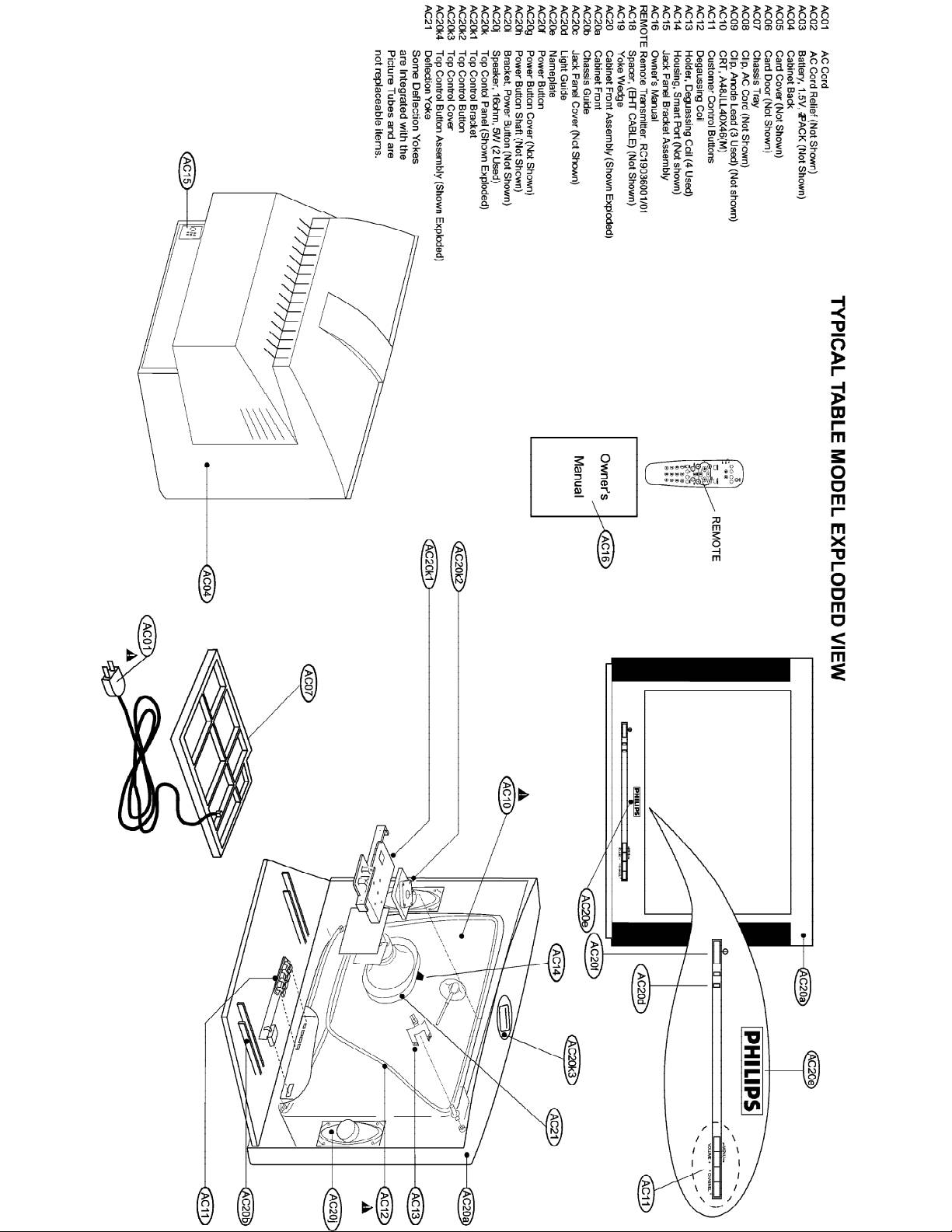
MAIN CABINET EXPLODED VIEW Page: 1 of 1

Philips Consumer Electronics
Technical Service Data
Service and Quality
Service Publications Dept.
One Philips Drive
P.O. Box 14810
Knoxville, TN 37914
Manual 7628
Model no.: 19LT010L/35
First Publish: 12760 S8
Rev. Date: 2002-06-06
Print Date: 13/07/2007
Electrical Adjustments
REFER TO SAFETY GUIDELINES
SAFETY NOTICE
HIMSELF WITH THE CHASSIS AND BE AWARE OF THE NECESSARY SAFETY PRECAUTIONS
TO BE USED WHEN SERVICING ELECTRONIC EQUIPMENT CONTAINING HIGH VOLTAGES.
CAUTION: USE A SEPARATE ISOLATION TRANSFORMER FOR THIS UNIT WHEN SERVICING
© Philips Electronics North America Corporation Visit our World Wide Web Site at http://www.forceonline.com
: ANY PERSON ATTEMPTING TO SERVICE THIS CHASSIS MUST FAMILIARIZE

Alignments - S8 Chassis
Index of this chapter:
1. General Alignment Conditions
2. Commercial Models SDAM Entry
3. Hardware Alignments
4. Software Alignments and Settings
Note: The Service Default Alignment Mode (SDAM) is described in the "Service Modes,
Error Codes and Fault Finding" section. SDAM menu navigation is performed by using
the MENU UP, MENU DOWN, MENU LEFT, and MENU RIGHT keys of the remote
control transmitter.
General Alignment Conditions
Perform all electrical adjustments under the following conditions:
•
AC voltage and frequency: 110V (± 10 %), 60Hz (± 5 %).
•
Connect the television set to the AC power via an isolation transformer.
•
Allow the television set to warm up for approximately20 minutes.
•
Measure the voltages and waveforms in relation to chassis ground (with the
exception of the voltages on the primary side of the power supply). Never use
heatsinks as ground.
•
Test probe: Ri > 10MO; Ci < 2.5pF.
•
Use an isolated trimmer/screwdriver to perform the alignments.
Service Default Alignment Mode (SDAM) Entry for
Commercial Models
Note: For commercial models, a master setup remote control is required in order to
access the Service Default Alignment Mode (SDAM).
1. Use the master setup remote control to identify the television’s operational mode
(either “consumer” or “commercial”). Place the master setup remote control in
setup mode by pressing the TV SETUP key.
2. Press the RECALL key. Information similar to the following will be displayed.
Status Item Status Data Meaning
SYSTEM STATUS
(L011TV-US4PV) Information title

MODE COMMERCIAL/CONSUMER Operational mode
N
CHANNEL CHANNEL, INPUT Currently tuned channel/input
DCM OFF/ON Data Comm. Module online/offline
CODES 209 222 1 33 Internal data for factory/service use
SIGNAL TUNED/NOT TUNED Valid signal present/absent
OP HRS 0031h Number of hours set has operated (hex)
ERRORS 0 0 0 0 0 Internal data for factory/service use
VERSION 3.3 Microprocessor software version
3. To change the television’s mode, ensure the master setup remote control is in
setup mode, then press the 0-2-4-9-9-5-MENU keys in order, without permitting
the display to time out while entering the key sequence.
ote: If the operational mode is changed, the television must be turned off and then back on to
complete the mode change. When the television is in consumer mode, do not use the master setup
remote control to activate commercial mode features.
4. When the television is in commercial mode, the Institutional Television Menu may
be accessed by pressing the MENU button. Though the specific items in the menu
will vary, information similar to the following will be displayed.
Menu Item Settings / Options
(MENU TITLE) SETUP MENU / MAIN MENU
LANGUAGE ENGLISH / ESPANOL / FRANCAIS
CHANNEL INSTALL >
CABLE TUNING ON / OFF
BRIGHTNESS - - - | - - - 31
COLOR - - - | - - - 31
CONTRAST - - - | - - - 31
SHARPNESS - - - | - - - 31
TINT - - - | | - - - 0
NOISE REDUCTION ON / OFF
SOUND MODE MONO / STEREO
SAP OFF / NO SAP / ON
AUDIO OUT FIXED / VARIABLE
BALANCE - - - | - - - 0
TREBLE - - - | - - - 31
BASS - - - | - - - 31
INCRED STEREO ON / OFF
AVL ON / OFF
VOLUME BAR ON / OFF
MIN VOLUME | - - - - - - 0
MAX VOLUME - - - - - - | 63
SWITCH ON VOLUME - - - | - - - 31
SWITCH ON CHANNEL CH. 1-125 / FRONT / AUX / S-VIDEO / CVI / STANDARD
POWER ON STANDARD / FORCED
CHANNEL DISPLAY NUMBER / LABEL / ALL / NONE
KEYBOARD LOCK ON / OFF
ESP 1 – 99 / OFF
AUDIO / VIDEO MUTE OFF / BLACK / BLUE
EXT AUD / VID OUT ON / OFF
WELCOME MESSAGE >

CHANNEL GUIDE POWER ON / OFF / ON
REMINDER ON / OFF
3 DIGIT ENTRY ON / OFF
A/CH A/V SWITCH ON – OFF
CC OFF / CC-1 / CC-2 / CC ON MUTE
SAVE CC ON / OFF
V-CHIP MENU ITEM ON / OFF
SAVE V-CHIP ON / OFF
V-CHIP SETUP >
SLEEPTIMER OFF / 15 / 30 / 45 / 60 / 90 / 120 / 180 / 240
EXIT >
5. After making changes to the settings, the EXIT option may be used to leave the
Institutional Television Menu.
Hardware Alignments
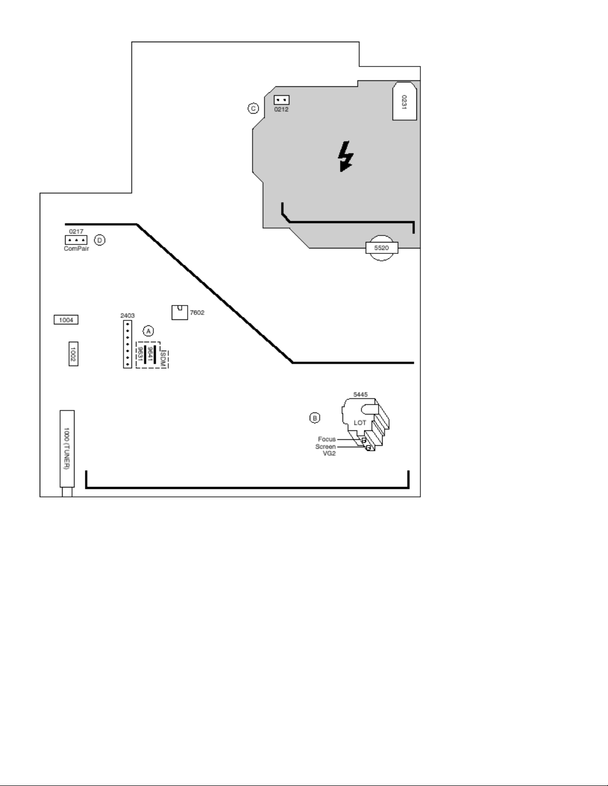
Figure: Top view LSP
Vg2 Adjustment
1. Enter SDAM:
•
Press the following key sequence on the remote control transmitter:
0-6-2-5-9-6-MENU
•
Do not allow the display to time out between entries while keying the
sequence.
2. Use the MENU UP/DOWN keys to highlight the WHITE TONE sub menu.

3. Press the MENU LEFT or MENU RIGHT key to enter the WHITE TONE sub
menu.
4. In the WHITE TONE sub menu, press the MENU UP/DOWN keys to select
NORMAL RED, NORMAL GREEN, or NORMAL BLUE.
5. Use the MENU LEFT/RIGHT keys to set the values of NORMAL RED, NORMAL
GREEN and NORMAL BLUE to 40.
6. Press the MENU button twice to enter the normal user menu.
7. In the normal user menu, use the MENU UP/DOWN keys to highlight the
PICTURE sub menu (if necessary).
8. Press the MENU LEFT/RIGHT keys to enter the PICTURE sub menu.
9. Use the MENU UP/DOWN keys to select PICTURE. Be sure to record the
current value of PICTURE.
10. Use the MENU LEFT/RIGHT keys to set the value of PICTURE to zero.
11. Use the MENU UP/DOWN keys to select BRIGHTNESS. Be sure to record the
current value of BRIGHTNESS.
12. Use the MENU LEFT/RIGHT keys to set the value of BRIGHTNESS to minimum
(OSD just visible in a dark room).
13. Press the MENU button twice to return to the top level SDAM menu.
14. Press the STATUS/EXIT button to hide the SDAM onscreen display.
15. Connect the RF output of a video pattern generator to the antenna input.
16. Input a "black picture" test pattern to the television set.
17. Set the oscilloscope to 50 V/div and the time base to 0.2 milliseconds (external
triggering on the vertical pulse).
18. Ground the scope at the CRT panel and connect a 10:1 probe to one of the
cathodes of the picture tube socket (see schematic diagram B).
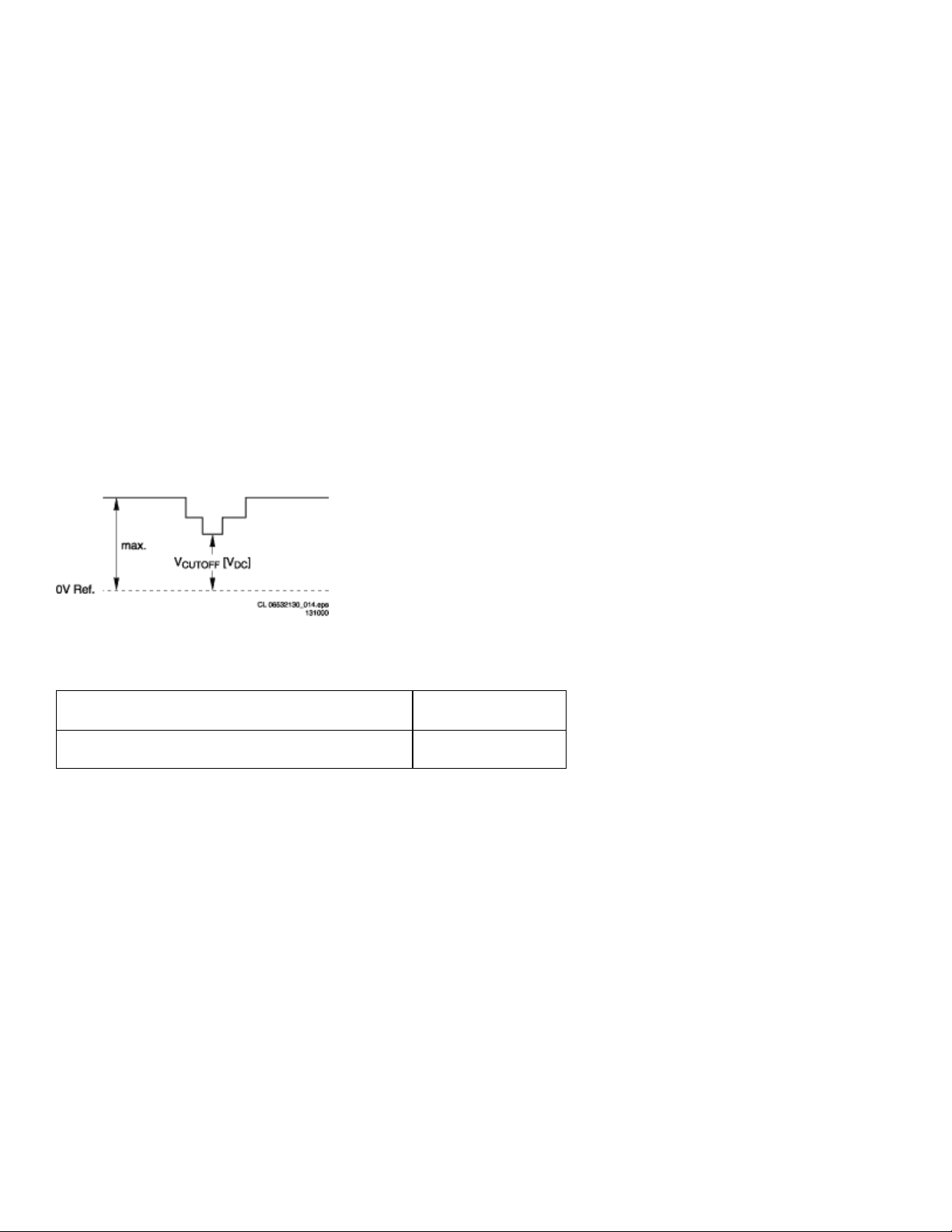
19. Measure the cut off pulse during first full line after the frame blanking (see Fig.
8-2). You will see two pulses, one being the cut off pulse and the other being the
white drive pulse. Choose the one with the lowest value; this is the cut off pulse.
20. Select the cathode with the highest DC voltage for the alignment. Adjust the V
Cut-Off of this gun with the SCREEN potentiometer(see Fig. 8-1) on the LOT to
the correct value (see table below).
21. Press the STATUS/EXIT button to display the SDAM onscreen display.
22. Press the MENU button to enter the normal user menu.
23. In the normal user menu, use the MENU UP/DOWN keys to highlight the
PICTURE sub menu (if necessary).
24. Press the MENU LEFT/RIGHT keys to enter the PICTURE sub menu.
25. Use the MENU UP/DOWN keys to select PICTURE.
26. Use the MENU LEFT/RIGHT keys to reset the value of PICTURE to the original
value.
27. Use the MENU UP/DOWN keys to select BRIGHTNESS.
28. Use the MENU LEFT/RIGHT keys to reset the value of BRIGHTNESS to the
original value.
29. Press the MENU button twice to return to the top level SDAM menu.
30. Use the POWER button on the remote control transmitter or the POWER button
on the television set to turn off the television set. This will save the changes
made in SDAM.
Figure: Waveform Vg2 alignment
V Cut-Off Values
Screen Size
13V/14", 14RF/15RF, 17",19V/20", 21" +135V +/- 4V
Cut-off Voltage
Focusing
1. Connect the RF output of a video pattern generator to the antenna input.
2. Input a circle or crosshatch test pattern to the television set.
3. Press the AUTO PICTURE button on the remote control transmitter repeatedly to
choose PERSONAL or MOVIES picture mode.
4. Adjust the FOCUS potentiometer (see Fig. 8-1)until the vertical lines near the left
and right sides of the screen, and near the horizontal center of the screen, are at
minimum width without visible haze.
Software Alignments and Settings
The following options are performed in the Service Default Alignment Mode (SDAM).
SDAM is described in the "Service Modes, Error Codes and Fault Finding" section.
The following alignments are explained:
•
Options
•
Tuner
•
White tone
•
Geometry
•
Audio
Options
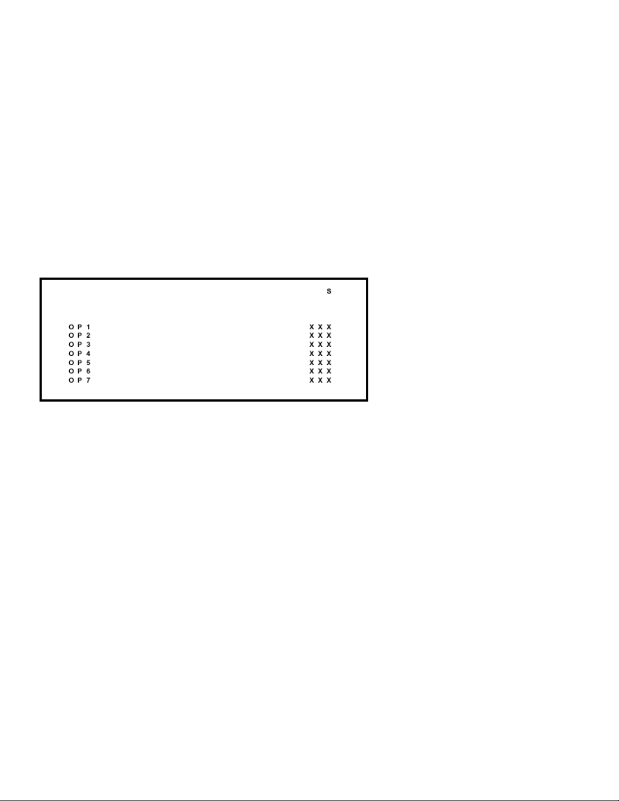
Figure: Options Screen
Options are used to control the presence or absence of certain features and hardware.
How to change an Option Byte
An Option Byte represents a number of different options. Changing these bytes directly
makes it possible to set all options very quickly. All options are controlled via seven
option bytes.
To change Option Byte(s):
1. Enter SDAM:
•
Press the following key sequence on the remote control transmitter:
0-6-2-5-9-6-MENU
•
Do not allow the display to time out between entries while keying the
sequence.
2. Use the MENU UP/DOWN keys to highlight the OPTIONS sub menu.
3. Press the MENU LEFT or MENU RIGHT key to enter the OPTIONS sub menu.

4. In the OPTIONS sub menu, press the MENU UP/DOWN keys to select OP 1
through OP 7.
5. Use the number keys on the remote control transmitter to enter a new value for
the selected option byte. The value must be entered as a three-digit value (for
example, "4" would be entered as "0-0-4").
6. The selected value must be between 0 and 255.
7. When all desired changes to the option bytes are made, press the MENU button
to return to the top level SDAM menu. This will save changes to the option byte
settings.
8. To ensure the option byte changes take effect:
•
Turn the television set OFF by using the POWER button on the remote
control transmitter or the local keyboard.
•
Disconnect the television set from AC power for at least ten seconds.
•
Reconnect the television set to AC power.
•
Turn the television set ON by using the POWER button on the remote
control transmitter or the local keyboard.
Option Byte Codes - S8 Chassis
MODEL OPTION BYTES
OP1 OP2 OP3 OP4 OP5 OP6 OP7
13LT010L/35 132 16 150 148 8 0 0
13PR12 W321 0 23 1 0 144 153 0
14LK10 0021 0 23 1 0 144 153 0
14LL10 0131 16 23 1 0 144 153 0
19LT010L/35 132 16 150 148 8 0 0
19LT220L/17 132 16 2 132 136 0 0
19PR11 C321 0 23 1 0 144 153 0
19PR11 C322 0 23 1 0 144 153 0
19PR16 C321 0 23 1 0 144 153 0
19PR16 C322 0 23 1 0 144 153 0
19PR30 C122 1 23 1 1 144 153 0
19PS35 S321 0 215 1 64 144 153 0
19PS35 S322 0 215 1 64 144 153 0
19PS45 S321 0 23 1 1 144 153 0
19PS45 S322 0 23 1 1 144 153 0
19PS50 S321 0 23 1 162 180 153 0
19ST220L/17 132 16 2 132 8 0 0
20LL20 0132 16 23 1 0 144 153 0
20LW20 2232 16 23 1 162 180 153 0
20LX20 0132 16 23 1 0 144 153 0
20LZ20 2222 16 23 1 1 144 153 0
CH0119 C322 133 16 2 132 0 0 0
HC0113 C321 1 16 148 148 0 0 0
HC0119 C322 1 16 148 148 0 0 0
PA0113 C321 221 218 35 36 0 0 0
PA0132 C321 223 222 43 40 0 0 0
PC0119 C322 133 16 2 132 0 0 0
PL0119 C322 1 16 0 132 0 0 0
* Option Byte Data for these models was not available at manual release.
Refer to future updates to this manual regarding these models.
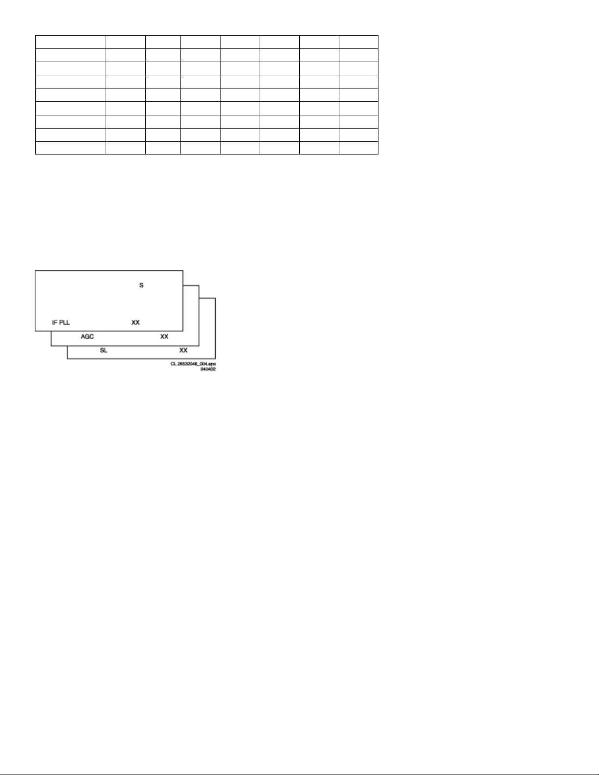
Tuner
Note: Described alignments are only necessary when the NVM (part reference
number7602) is replaced.
Figure: Tuner alignment screens
IF PLL
This adjustment is auto-aligned. Therefore, no action is required.
AGC (AGC take over point)
1. Connect the RF output of a video pattern generator to the antenna input.
2. Input a color bar test pattern to the television set.
3. Set the amplitude of the video pattern generator to 10 mV and set the frequency
to 61.25 MHz (channel 3).
4. Connect a DC multimeter to pin 1 of the tuner(item 1000 on the main chassis).
5. Enter SDAM:
•
Press the following key sequence on the remote control transmitter:
0-6-2-5-9-6-MENU
•
Do not allow the display to time out between entries while keying the
sequence.

6. Use the MENU UP/DOWN keys to highlight the TUNER sub menu.
7. Press the MENU LEFT/RIGHT keys to enter the TUNER sub menu.
8. Use the MENU UP/DOWN keys to select AGC.
9. Use the MENU LEFT/RIGHT keys to adjust the AGC value (default value is 27)
until the voltage at pin 1 of the tuner lies between 3.8V and 2.3V.
10. Press the MENU button to return to the top level SDAM menu.
11. To ensure the AGC change takes effect:
•
Turn the television set OFF by using the POWER button on the remote
control transmitter or the local keyboard.
•
Disconnect the television set from AC power for at least ten seconds.
•
Reconnect the television set to AC power.
•
Turn the television set ON by using the POWER button on the remote
control transmitter or the local keyboard.
SL (Slicing Level)
This adjustment sets the sync slicing level for non-standard signals.
SL should be turned ON to help correct picture instability in premium decoded cable
channels.
OFF: slicing level dependent on noise detector
ON: fixed slicing level of 70%
To adjust SL:
1. Enter SDAM:
•
Press the following key sequence on the remote control transmitter:
0-6-2-5-9-6-MENU
•
Do not allow the display to time out between entries while keying the
sequence.
2. Use the MENU UP/DOWN keys to highlight the TUNER sub menu.
3. Press the MENU LEFT/RIGHT keys to enter the TUNER sub menu.
4. Use the MENU UP/DOWN keys to select SL.
5. Use the MENU LEFT/RIGHT keys to toggle SL "Off" and "On"
6. Press the MENU button to return to the top level SDAM menu.
7. To ensure the SL setting is saved:
•
Turn the television set OFF by using the POWER button on the remote
control transmitter or the local keyboard.
•
Disconnect the television set from AC power for at least ten seconds.
•
Reconnect the television set to AC power.
•
Turn the television set ON by using the POWER button on the remote
control transmitter or the local keyboard.
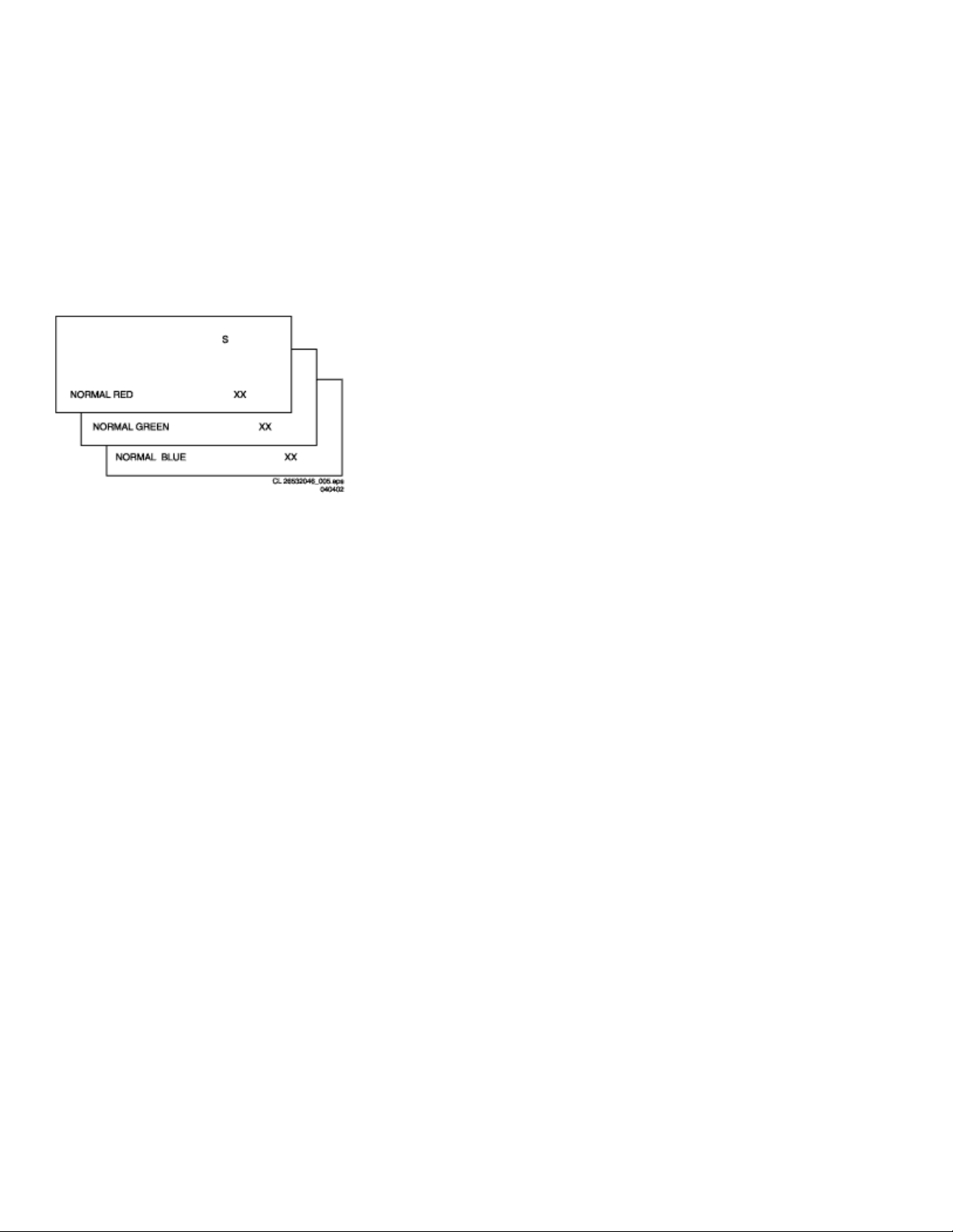
White Tone
Figure: White tone alignment screens
The values of the black cut off level can be adjusted in the WHITE TONE sub menu.
Normally, no alignment is needed for WHITETONE, and the given default values are
used.
Default settings for NORMAL (color temperature = 9600K):
•
NORMAL RED = 40
•
NORMAL GREEN = 40
•
NORMAL BLUE = 40
To adjust NORMAL RED, NORMAL GREEN, and NORMAL BLUE:
1. Enter SDAM:
•
Press the following key sequence on the remote control transmitter:
0-6-2-5-9-6-MENU
•
Do not allow the display to time out between entries while keying the
sequence.
2. Use the MENU UP/DOWN keys to highlight the WHITE TONE sub menu.
3. Press the MENU LEFT/RIGHT keys to enter the WHITE TONE sub menu.
4. Use the MENU UP/DOWN keys to select NORMAL RED, NORMAL GREEN, or

NORMAL BLUE.
5. Use the MENU LEFT/RIGHT keys to adjust the value of NORMAL RED,
NORMAL GREEN, or NORMAL BLUE.
6. When all desired changes to the WHITE TONE submenu values are made, press
the MENU button to return to the top-level SDAM menu.
7. To ensure the WHITE TONE settings are saved:
•
Turn the television set OFF by using the POWER button on the remote
control transmitter or the local keyboard.
•
Disconnect the television set from AC power for at least ten seconds.
•
Reconnect the television set to AC power.
•
Turn the television set ON by using the POWER button on the remote
control transmitter or the local keyboard.
Geometry
The geometry alignments menu contains several items for correct picture geometry
alignment.
1. Connect the RF output of a video pattern generator to the antenna input.
2. Input a crosshatch test pattern to the television set.
3. Set the amplitude of the video pattern generator to at least 1mV and set the
frequency to 61.25MHz (channel 3).
4. Press the AUTO PICTURE button on the remote control transmitter repeatedly to
choose PERSONAL or MOVIES picture mode.
5. Enter SDAM:
•
Press the following key sequence on the remote control transmitter:
0-6-2-5-9-6-MENU
•
Do not allow the display to time out between entries while keying the
sequence.
6. Use the MENU UP/DOWN keys to highlight the GEOMETRY sub menu.
7. Press the MENU LEFT/RIGHT keys to enter the GEOMETRY sub menu.
8. Use the MENU UP/DOWN keys to highlight either the HORIZONTAL sub menu
or the VERTICAL sub menu.
9. Press the MENU LEFT/RIGHT keys to enter either the HORIZONTAL sub menu
or the VERTICAL sub menu.
10. Use the MENU UP/DOWN keys to select items in the HORIZONTAL sub menu
or the VERTICAL sub menu.
11. Use the MENU LEFT/RIGHT keys to adjust the values of items in the
HORIZONTAL and VERTICAL sub menus.
12. When all desired changes to the HORIZONTAL and VERTICAL sub menu values
are made, press the MENU button twice to return to the top level SDAM menu.
13. To ensure the GEOMETRY settings are saved:
•
Turn the television set OFF by using the POWER button on the remote
control transmitter or the local keyboard.
•
Disconnect the television set from AC power for at least ten seconds.
•
Reconnect the television set to AC power.
•
Turn the television set ON by using the POWER button on the remote
control transmitter or the local keyboard.
The following alignments can be performed in the GEOMETRY submenu:
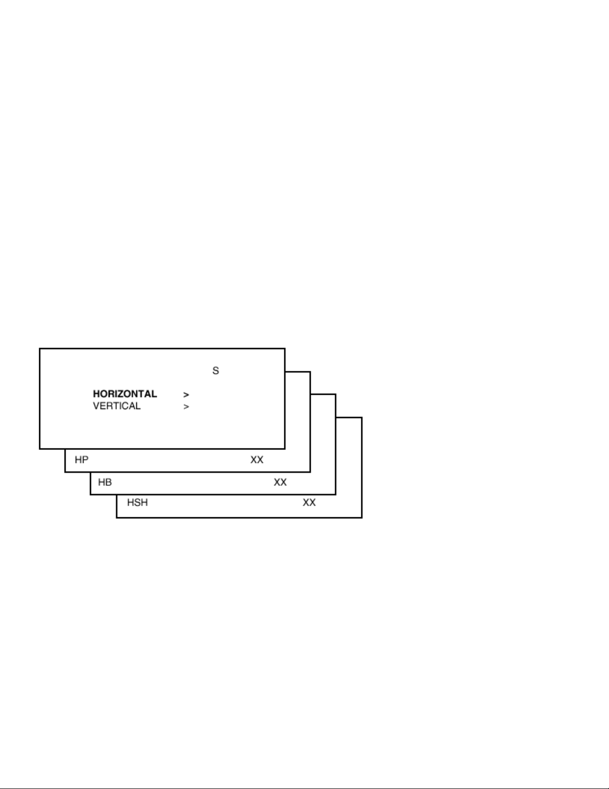
Figure: Horizontal geometry alignment screens
Horizontal:
•
Horizontal Parallelogram (HP). Aligns straight vertical lines at the top and the
bottom of the screen; vertical rotation around the center.
•
Horizontal Bow(HB). Aligns straight horizontal lines at the top and the bottom of
the screen; horizontal rotation around the center.
•
Horizontal Shift(HSH). Aligns the horizontal center of the picture to the
horizontal center of the CRT.
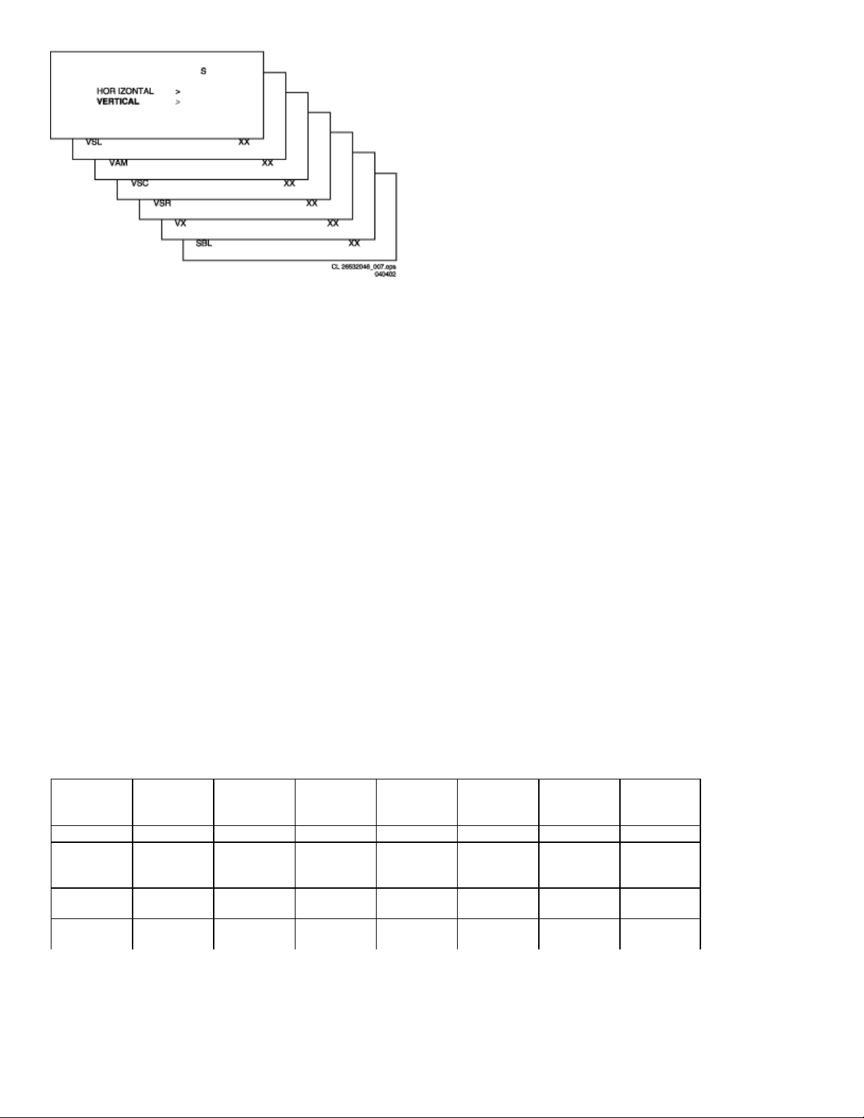
Figure: Vertical geometry alignment screens
Vertical:
•
Vertical slope (VSL). Aligns the picture so the proportions are the same at the
top and bottom of the screen. This alignment must be performed first, before all
other vertical alignments. Turning SBL ON will assist in performing this
alignment.
•
Vertical Amplitude(VAM). Aligns the height of the picture (other vertical
alignments are NOT compensated).
•
Vertical S-Correction(VSC). Aligns the vertical linearity, so that the vertical
intervals of the grid-patterns are the same over the entire height of the screen.
•
Vertical Shift(VSH). Aligns the vertical center of the picture to the vertical center
of the CRT. After performing this alignment, it may be necessary to perform the
VAM alignment again.
•
Vertical Zoom( VX). Adjusts picture height.
•
Service blanking(SBL). Turns the blanking of the lower half of the screen ON or
OFF (to be used in combination with the vertical slope alignment).
The table below lists the default GEOMETRY values for the different television sets.
Default Geometry Values
Alignment Description 13L100/85R
Mono
HP Hor.
Parallelogra
HB Hor. Bow 31 31 31 31 31 31
HSH Hor. S hift 23 23 23 23 23 23
31 31 31 31 31 31
19L135/37R 19L145/37R
BTSC-NON-
19L145/85R
BTSC-NON-
20L145/37R
BTSC DBX
20L135/37R
VSL Vert. Slope 31 38 31 31 31 31
VAM Vert.
Amplitude
VSC Vert. S
-correction
VSH Vert. S hift 30 35 26 26 26 26
VX Vert. Zoom 25 25 25 25 25 25
26 34 26 26 26 26
23 23 23 23 23 23
Audio
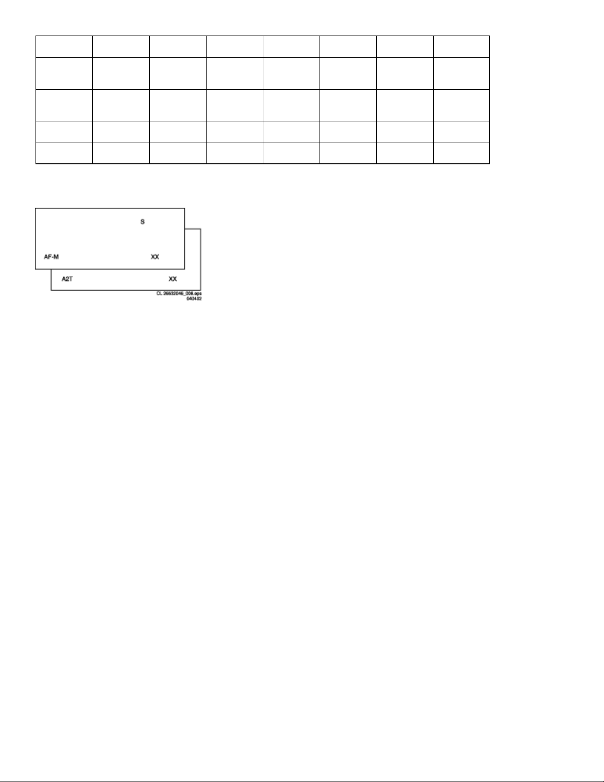
Figure: Audio alignment screens
No alignments are necessary for the AUDIO sub menu. Use the default values.
AF-M
Default value is 300.
To adjust AF-M:
1. Enter SDAM:
•
Press the following key sequence on the remote control transmitter:
0-6-2-5-9-6-MENU
•
Do not allow the display to time out between entries while keying the
sequence.
2. Use the MENU UP/DOWN keys to highlight the AUDIO sub menu.
3. Press the MENU LEFT/RIGHT keys to enter the AUDIO sub menu.
4. Use the MENU UP/DOWN keys to select AF-M.
5. Use the MENU LEFT/RIGHT keys to adjust the value of AF-M to 300.
6. Press the MENU button to return to the top level SDAM menu.
7. To ensure the AF-M setting is saved:

•
Turn the television set OFF by using the POWER button on the remote
control transmitter or the local keyboard.
•
Disconnect the television set from AC power for at least ten seconds.
•
Reconnect the television set to AC power.
•
Turn the television set ON by using the POWER button on the remote
control transmitter or the local keyboard.
A2T (TV A2 Threshold)
Default value is 250.
To adjust A2T:
1. Enter SDAM:
•
Press the following key sequence on the remote control transmitter:
0-6-2-5-9-6-MENU
•
Do not allow the display to time out between entries while keying the
sequence.
2. Use the MENU UP/DOWN keys to highlight the AUDIO sub menu.
3. Press the MENU LEFT/RIGHT keys to enter the AUDIO sub menu.
4. Use the MENU UP/DOWN keys to selectA2T.
5. Use the MENU LEFT/RIGHT keys to adjust the value of A2T to 250.
6. Press the MENU button to return to the top level SDAM menu.
7. To ensure the A2T setting is saved:
•
Turn the television set OFF by using the POWER button on the remote
control transmitter or the local keyboard.
•
Disconnect the television set from AC power for at least ten seconds.
•
Reconnect the television set to AC power.
•
Turn the television set ON by using the POWER button on the remote
control transmitter or the local keyboard.

Philips Consumer Electronics
Technical Service Data
Service and Quality
Service Publications Dept.
One Philips Drive
P.O. Box 14810
Knoxville, TN 37914
Manual 7628
Model no.: 19LT010L/35
First Publish: 12760 S8
Rev. Date: 2002-06-06
Print Date: 13/07/2007
Parts List
REFER TO SAFETY GUIDELINES
SAFETY NOTICE
HIMSELF WITH THE CHASSIS AND BE AWARE OF THE NECESSARY SAFETY PRECAUTIONS
TO BE USED WHEN SERVICING ELECTRONIC EQUIPMENT CONTAINING HIGH VOLTAGES.
CAUTION: USE A SEPARATE ISOLATION TRANSFORMER FOR THIS UNIT WHEN SERVICING
© Philips Electronics North America Corporation Visit our World Wide Web Site at http://www.forceonline.com
: ANY PERSON ATTEMPTING TO SERVICE THIS CHASSIS MUST FAMILIARIZE
 Loading...