


A/C-D/C
Battery Backup
Sump Pump System
Instruction Manual & Safety Warnings
Table of Contents
Important Safety Warnings and |
|
Instructions |
|
Electrical precautions |
1 |
Battery preparation |
1 |
Battery precautions |
1 |
Introduction |
|
Items included in system |
2 |
Additional items needed |
2 |
Replacement parts list |
2 |
System specifications |
2 |
Pump & Pipe |
|
Installation Instructions |
|
Installation options |
3 |
Direct discharge to outside |
4 |
Connection to existing discharge |
5 |
Direct discharge for narrow sumps |
6 |
Connection to existing discharge |
|
for narrow sumps |
7 |
Battery Instructions |
8,9 |
Control Unit Connections |
|
Positioning the float switch |
9 |
Connecting the pump |
9 |
Installing the battery fluid sensor |
10 |
Connecting the battery |
10 |
Connecting two batteries |
10 |
Connecting to AC power |
10 |
Understanding the Warning |
|
Lights and Alarms |
|
Silencing the alarm |
10 |
Battery fluid is low |
11 |
Battery problem |
11 |
Cleaning battery terminals |
11 |
Replacing the battery |
12 |
Power failure |
13 |
Pump or fuse failure |
13 |
Pump was activated |
14 |
Replacing the pump |
14 |
Battery power level |
14 |
Testing the System |
|
Testing the float switch |
15 |
Connecting the Remote Alarm |
15 |
Parts & Service Information |
|
Technical support |
15 |
Troubleshooting Guide |
16 |
Warranty |
17 |
Other Products |
18 |
IMPORTANT: Even if you have the Pro Series backup sump pump system installed by someone else, you must read and follow the safety information contained in this manual. Failure to do so could result in property damage, serious injury, or death.
Important Safety
Warnings & Instructions
SAVE THESE INSTRUCTIONS. This manual contains important SAFETY WARNINGS and OPERATING INSTRUCTIONS for the PHCC Pro Series 2400 battery backup sump pump system. You will need to refer to it before attempting any installation or maintenance. ALWAYS keep these instructions with the unit so that they will be easily accessible.
Failure to read and follow these warnings and instructions could result in property damage, serious injury, or death. It is important to read this manual, even if you did not install the Pro Series backup sump pump system, since this manual contains safety information regarding the use and maintenance of this product. DO
NOT DISCARD THIS MANUAL.
ELECTRICAL PRECAUTIONS
! DANGER
Risk of electrical and fire hazard. May result in death, serious injury, shock or burns. To help reduce these risks, observe the following precautions:
•DO NOT walk on wet areas of the basement until all power has been turned off. If the main power supply is in a wet basement, call an electrician.
•NEVER handle the control unit with wet hands or while standing on a wet surface.
•ALWAYS unplug the control unit and disconnect the cables from the battery before attempting any maintenance or cleaning.
•ALWAYS unplug the main pump when installing or servicing the backup pump or float switch to avoid electric shock.
•DO NOT expose the control unit to rain or snow.
•DO NOT pull the cord when disconnecting the control unit. Pull the plug.
•MAKE SURE THERE IS A PROPERLY GROUNDED RECEPTACLE AVAILABLE. This pump is wired with a 3-prong grounded plug. To reduce the risk of electrical shock, be
certain that it is only connected to a properly grounded 3-prong receptacle. If you have a 2-prong receptacle, have a licensed electrician replace it with a 3-prong receptacle according to local codes and ordinances.
•DO NOT use an extension cord. The electrical outlet should be within the length of the pump’s power cord, and at least 4 feet above the floor.
•DO NOT use an attachment not recommended or sold by the manufacturer. It may result in a risk of fire or injury from an electrical shock.
•DO NOT operate the computer control unit if it has received a sharp blow, been dropped, or otherwise damaged in any way.
•DO NOT disassemble the control unit.
•DO protect the electrical cord from sharp objects, hot surfaces, oil and chemicals. Avoid kinking the cord.
•MAKE SURE the supply circuit has a fuse or circuit breaker rated to handle the power requirements of this system.
•DO NOT use in pits handling raw sewage, salt water or other hazardous materials.
When service is required, contact Glentronics technical support at 800-991-0466, option #3, or send an e-mail to service@glentronics.com. Return the control unit to the manufacturer for any repairs at the following address:
Glentronics, Inc.
645 Heathrow Drive
Lincolnshire, IL 60069-4205
BATTERY PREPARATION
! WARNING / POISON
Sulfuric acid can cause blindness or severe burns. Avoid contact with skin, eyes, or clothing. In the event of an accident, flush with water and call a physician immediately. KEEP OUT OF REACH OF CHILDREN.
To help reduce these risks, observe the following precautions:
•Someone should be within range of your voice or close enough to come to your aid when you work near a lead-acid battery.
•Have plenty of fresh water and soap nearby in case battery acid contacts skin, clothing or eyes.
•Wear eye and clothing protection and avoid touching your eyes while working with battery acid or working near the battery.
•If battery acid contacts skin or clothing, wash immediately with soap and water. If acid enters eye, immediately flood eye with running cold water for at least 15 minutes and get prompt medical attention.
•Battery posts and terminals contain lead and lead compounds, chemicals known to the State of California to cause cancer and reproductive harm. Wash hands after handling.
BATTERY PRECAUTIONS
! DANGER
Explosive gases could cause serious injury or death. Cigarettes, flames or sparks could cause battery to explode in enclosed spaces. Charge in a well-ventilated area. Always shield eyes and face from battery. Keep vent caps tight and level.
To help reduce these risks, observe the following precautions:
•NEVER smoke or allow a spark or flame in the vicinity of the battery.
•Use the Pro Series control unit for charging a LEAD-ACID battery only. DO NOT use the control unit for charging dry-cell batteries that are most commonly used with home appliances.
•Be sure the area around the battery is wellventilated.
•When cleaning or adding water to the battery, first fan the top of the battery with a piece of cardboard (or another non-metallic material) to blow away any hydrogen or oxygen gas that may have been emitted from the battery.
•DO NOT drop a metal tool onto the battery. It might spark or short-circuit the battery and cause an explosion.
•Remove personal metal items such as rings, bracelets, watches, etc. when working with a lead-acid battery. A short circuit through one
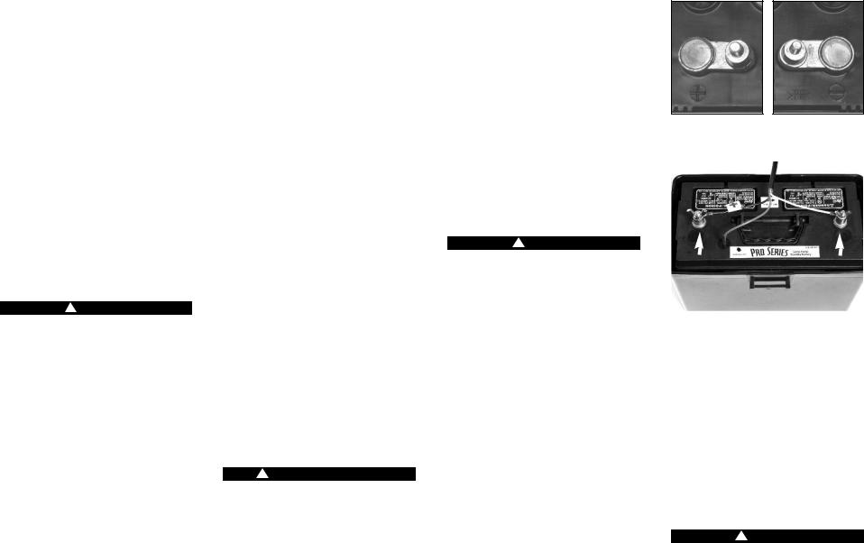
POSITIVE POST HAS |
NEGATIVE POST HAS |
LARGER DIAMETER |
SMALLER DIAMETER |
POSITIVE |
NEGATIVE |
POST |
POST |
|
|
of these items can melt it, causing a severe burn.
•ALWAYS remove the power cord from the electrical outlet before connecting or disconnecting the battery cables.
•Check the polarity of the battery posts. The POSITIVE (+) battery post usually has a larger diameter than the NEGATIVE (-) post.
•When connecting the battery cables, first connect the small ring on the end of the WHITE wire to the NEGATIVE (-) post of the battery, and then connect the large ring on the end of the BLACK wire to the POSITIVE (+) post of the battery.
! DANGER
Do not use this system to pump flammable or explosive fluids such as gasoline, fuel oil, kerosene, etc.
Page 1

Introduction |
|
|
|
To extend the battery run time, two batteries may |
The internal construction of some wet cell batteries |
||||||||||
|
|
|
|
be connected to the Pro Series 2400 system by |
may not be compatible with this system. |
||||||||||
The PHCC Pro Series 2400 A/C-D/C backup sump |
purchasing a second battery and acid pack, as |
Glentronics can not guarantee the compatibility of |
|||||||||||||
well as a set of battery jumper cables. |
Jumper |
other brands of batteries. The use of a Pro Series |
|||||||||||||
pump is designed as an emergency backup |
|||||||||||||||
cables specifically designed for this use are |
battery is HIGHLY recommended. |
||||||||||||||
system to support your main AC sump pump, and |
|||||||||||||||
available from the manufacturer, Glentronics, Inc. |
• |
1½” rigid PVC pipe and fittings |
|||||||||||||
it will automatically begin pumping any time the |
|||||||||||||||
|
|
|
|
|
• |
PVC primer and cement |
|||||||||
float switch is activated by rising water. |
|
|
|
|
|
|
|||||||||
|
The Pro Series Sump Pump System includes: |
• |
A union with hose clamps or a “Y” connector |
||||||||||||
|
|
|
|
||||||||||||
If your main AC pump breaks or is unable to keep |
• |
A control unit |
with a dual float switch, a |
|
and two (2) check valves, depending on the |
||||||||||
|
battery fluid level sensor, battery cables, a 5 |
|
installation method you use |
||||||||||||
up with all the incoming water, the Pro Series |
|
|
|||||||||||||
|
amp AC fuse, and a 20 amp DC fuse |
|
|
• |
A 1½” PVC pipe adapter (1½” SLIP x 1½” |
||||||||||
pump is capable of running without discharging |
|
|
|
||||||||||||
• |
A metal hose clamp for mounting the float |
|
MIPT) |
|
|
||||||||||
the battery, as long as the AC power is on. As |
|
|
|
||||||||||||
|
switch |
|
|
|
• |
A surge protector (recommended) |
|||||||||
soon as the AC power is interrupted, the battery |
|
|
|
|
|||||||||||
• |
A pump |
|
|
|
• Six (6) quarts of 1.265 specific gravity battery |
||||||||||
takes over. Should any malfunction or emergency |
|
|
|
||||||||||||
• |
A battery box |
|
|
|
|
acid |
|
|
|||||||
occur that involves the sump pump, the battery, |
|
|
|
|
|
|
|||||||||
• |
A battery filler |
bottle for adding |
distilled |
|
|
|
|
|
|
|
|||||
or the AC power, the Pro Series system will sound |
|
|
|
|
|
|
|
||||||||
|
water to the battery |
|
|
|
|
|
|
|
|
||||||
an alarm. A light on the display panel of the |
|
|
|
|
|
|
|
|
|
||||||
|
|
|
|
|
|
|
|
|
|
|
|||||
control unit will indicate the cause of the alarm |
You will also need to supply: |
|
|
|
|
|
|
|
|
||||||
and the corrective action. |
|
|
|
|
|
|
|
|
|
|
|
||||
|
|
|
• |
A Pro Series 2200 Standby Battery or a Pro |
|
|
|
|
|
|
|
||||
|
|
|
|
|
|
|
|
|
|
|
|||||
For added reliability, the |
float switch has, not |
|
Series Maintenance-Free Battery (B12-90) |
|
|
|
|
|
|
|
|||||
|
DO NOT use an automotive battery with this |
|
|
|
|
|
|
|
|||||||
one, but two floats mounted within a protective |
|
|
|
|
|
|
|
|
|||||||
|
system |
|
|
|
|
|
|
|
|
|
|||||
cage. Should one float fail to operate, the second |
|
|
|
|
|
|
|
|
|
|
|||||
|
DO NOT use a Pro Series 1000 battery with this |
|
|
|
|
|
|
|
|||||||
float automatically activates the |
pump. |
The |
|
|
|
|
|
|
|
|
|||||
|
system. It will not run the pump as long as the |
|
|
|
|
|
|
|
|||||||
protective cage prevents |
debris or |
other |
wires |
|
|
|
|
|
|
|
|
||||
|
Pro Series 2200 or B12-90 battery |
|
|
|
|
|
|
|
|
||||||
from interfering with the movement of the floats. |
|
|
|
|
|
|
|
|
|
||||||
|
|
|
|
|
|
|
|
|
|
|
|||||
|
|
|
|
|
|
|
|
|
|
|
|
|
|
|
|
|
|
|
|
|
|
Battery Box |
|
|
|
|
|
|
|
|
|
Control Unit |
|
|
|
|
|
|
|
|
|
|
|
|
|
|
|
|
|
|
|
|
|
|
|
|
|
|
|
|
|
||
|
|
|
|
|
|
|
|
|
|
|
For narrow sump pits you will need |
||||
|
|
|
|
|
|
|
|
|
|
|
some additional parts: |
||||
|
|
|
|
|
|
|
|
|
|
|
• An “L” bracket at least six (6) inches |
||||
|
|
|
|
|
|
|
|
|
|
|
|
|
long (preferably one that will not |
||
|
|
|
|
|
|
|
|
|
|
|
|
|
rust) |
||
|
|
|
|
|
|
|
|
|
|
|
• |
Two (2) stainless steel hose clamps |
|||
|
|
|
|
|
|
|
|
|
|
|
• |
One (1) stainless steel screw (#8-32 |
|||
|
|
|
|
Dual |
|
|
Battery |
|
|
|
|
x 3/4”), a matching washer & nut |
|||
|
|
|
|
|
|
|
|
|
|
|
|
||||
|
|
|
|
Float |
|
|
|
|
|
|
|
||||
|
|
|
|
|
Filler |
|
|
To connect two batteries you will |
|||||||
|
|
|
|
Switch |
|
|
|
||||||||
|
|
|
|
|
Bottle |
|
|
need: |
|||||||
|
|
|
|
|
|
|
|
|
|||||||
|
|
|
|
|
|
|
|
|
|
|
• |
Two (2) batteries of similar age and |
|||
|
|
|
|
|
|
|
|
|
|
|
|
|
capacity (so they will have equal |
||
Battery Wires |
|
Fluid Sensor |
Hose Clamp |
Pump |
|
|
|
|
|
|
power) |
||||
|
|
|
|
|
|
• |
Another battery box (optional) |
||||||||
|
|
|
|
|
|
|
|
|
|
|
|||||
•Two (2) acid packs to fill the dry batteries
•A set of battery cables with rings on both ends to connect the two batteries together (available from Glentronics, Inc.)
Use of a Pro Series Klunkless Check Valve™ will provide quieter operation. (See page 18 for more information.)
Replacement Part Numbers
Pump . . . . . . . . . . . . . . . . . . . . . . .1011010 Float switch assembly w/hose clamp . .1020011 Fluid sensor assembly . . . . . . . . . . . .1014001 Battery box . . . . . . . . . . . . . . . . . . .1113003 Battery filler bottle . . . . . . . . . . . . . . .BFB-P Battery jumper cable for 2 batteries . . . . . .BJC
Call 800-991-0466, option #3 to order parts.
System Specifications
Power supply requirements . . . . . .115 volts AC Pumping capacity . . . . . . . . . .4000 GPH @ 0’ Pumping capacity . . . . . . . . .2400 GPH @ 10' Pumping capacity . . . . . . . . .1600 GPH @ 12' Pumping capacity . . . . . . . . . .600 GPH @ 15' Pump dimensions w/elbow . . . . . .81⁄2 H x 9” W Pump housing & strainer . . . . . .non-corrosive,
will not rust Pump . . .can run dry for short periods of time; can be used in sumps with water softener Float switch . . . . . . . . . .independent, can be set at any level
Page 2
Pump & Pipe
Installation Instructions
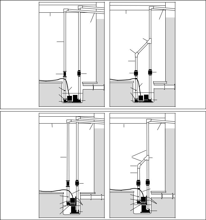
There are two basic methods that can be used to install the pump, a direct discharge to the outside of the building, or a connection to an existing discharge pipe. The same two options apply in very narrow sump pits where the backup pump must be mounted above the main pump.
Whenever possible, install your Pro Series backup pump with a direct discharge to the outdoors. By using this method, there will always be an outlet for the water from the sump. During times of very heavy rain, many storm sewers fill up. If your pump is trying to discharge water into a full sewer, there is nowhere for the water to go. By discharging directly outdoors, there is always an outlet for the water that is pumped out of the sump. For this method, you will need to drill a hole through a floor joist or the foundation from the basement to the outside of the house.
If the direct discharge method is not possible or convenient, the Pro Series pump can be connected to the same line as your main AC sump pump by installing a “Y” connector and two (2) check valves.
In most cases, the backup pump will fit next to the main AC pump in the sump pit. In very narrow pits, the backup pump can be mounted above the main AC pump. Try to fit the backup pump on the floor of the sump first. Make sure there is enough room so the backup pump and the main pump do not touch each other.
Select the installation method that will best suit your needs from the diagrams at the right. Full instructions for each installation method are provided on the following pages.
Installation will take a couple hours.
Page 3
NORMAL SUMP PIT |
|
|
|
|
|
|
|
INSTALLATIONS |
|
|
|
|
|
|
|
|
|
|
|
FLOOR |
|
|
|
|
FLOOR |
|
|
JOIST |
|
|
|
|
JOIST |
|
|
|
SLOPE |
|
|
|
|
SLOPE |
|
|
PIPE |
|
|
|
|
|
|
DOWN |
|
|
|
|
|
PIPE |
|
|
|
|
|
|
|
DOWN |
|
|
|
|
|
|
RIGID |
|
|
"Y" CONNECTOR |
|
|
|
|
|
|
|
|
|
|
|
|
1-1/2" |
|
|
|
|
|
|
|
PVC PIPE |
|
|
|
|
|
|
|
|
|
|
45º ELBOW |
|
|
|
|
|
|
|
RIGID |
|
|
|
|
|
|
|
1-1/2" |
|
|
|
|
|
|
|
PVC PIPE |
|
|
|
|
UNION |
CHECK |
|
CHECK |
CHECK |
|
|
|
OR CHECK |
|
VALVE |
VALVE |
|
|
|
|
VALVE |
|
|
|
|||
|
VALVE |
|
|
|
|
|
|
|
|
|
|
|
|
|
|
|
|
|
|
PUMP |
|
|
|
|
|
PUMP |
|
WIRE |
|
|
|
|
DRILL 1/8" HOLE |
|
|
|
|
|
|
|
WIRE |
|
1/8" HOLE |
DRAIN |
TILE |
Installation B |
|
|
IF CHECK |
DRAIN |
TILE |
||||
|
|
|
|||||
Installation A |
VALVE USED |
|
|
PIPE |
|
|
Connection |
|
|
|
|
|
|||
Direct Discharge |
PIPE ADAPTER |
|
|
ADAPTER |
|
|
to Existing |
|
MAIN |
|
|
MAIN |
|
||
to Outside |
PRO SERIES |
|
PRO SERIES |
|
Discharge Pipe |
||
BACKUP PUMP |
AC PUMP |
|
BACKUP PUMP |
AC PUMP |
|
||
Page 4 |
|
|
|
|
|
|
Page 5 |
NARROW SUMP PIT |
|
|
|
|
|
|
|
INSTALLATIONS |
|
|
|
|
|
|
|
|
FLOOR |
|
|
FLOOR |
|
|
|
|
JOIST |
SLOPE |
|
JOIST |
SLOPE |
|
|
|
|
PIPE |
|
|
PIPE |
|
|
|
|
DOWN |
|
|
DOWN |
|
|
|
|
|
|
|
"Y" |
|
|
|
RIGID |
|
|
RIGID |
CONNECTOR |
|
|
|
|
|
|
|
|
||
|
1-1/2" |
|
|
1-1/2" |
"Y" |
|
|
|
PVC PIPE |
|
|
PVC PIPE |
CONNECTOR |
|
|
45º ELBOW
RIGID 1-1/2" PVC PIPE
UNION |
|
CHECK |
CHECK |
|
|
|
CHECK |
OR CHECK |
|
|
|
|
VALVE |
||
|
VALVE |
VALVE |
|
|
|
||
VALVE |
|
|
|
|
|
||
|
|
|
|
|
|
|
|
|
PUMP WIRE |
|
PUMP WIRE |
|
|
|
|
|
|
|
|
|
||
|
DRILL 1/8" HOLE |
|
1/8" HOLE |
DRAIN |
TILE |
|
|
|
DRAIN |
TILE |
Installation D |
||||
|
IF CHECK |
|
|
||||
|
|
PIPE ADAPTER |
|
|
|||
Installation C |
VALVE USED |
HOSE |
PRO SERIES |
HOSE |
|
Connection |
|
PIPE ADAPTER |
|
||||||
Direct Discharge |
PRO SERIES |
CLAMPS |
BACKUP PUMP |
CLAMPS |
to Existing |
||
|
|
||||||
|
|
|
|
|
|||
to Outside |
BACKUP PUMP |
MAIN |
"L" BRACKET |
MAIN |
|
Discharge Pipe |
|
AC PUMP |
|||||||
|
|||||||
Page 6 |
"L" BRACKET |
AC PUMP |
|
|
|
Page 7 |
|
|
|
|
|
||||
|
|
|
|
|
|
||

Pump & Pipe
Installation Instructions
INSTALLATION A:
DIRECT DISCHARGE TO THE OUTSIDE OF THE BUILDING (Diagram A)
! DANGER
Unplug the main AC pump when installing the backup pump to avoid electric shock. Failure to do so could cause serious injury or death.
1.Cut a piece of 1½” rigid PVC pipe long enough to reach from the bottom of the sump pit to one (1) foot above the floor. Prime and cement it to a 1½” pipe adapter, then screw the adapter into the pump.
2.Secure the pump wire so that the plug on the end will not fall into the sump. Attach the wire to the pipe with a piece of tape.
3.Place the pump with the PVC pipe attachment on the bottom of the sump floor next to the main AC pump. The pumps should not touch each other. Do not mount
1
2
the pump to any existing pipes; it should be placed on the floor of the sump. A brick may be placed under the pump if there are rocks or other debris on the sump floor that may clog the pump.
4.Attach a union or a check valve to the top of the 1½” pipe. This will allow the pump to be removed easily, should the need arise.
The path of the rest of the pipe and the details of each installation will vary. Using sound plumbing practices, route the discharge pipe to an exterior wall via the shortest path with the fewest turns. More turns will reduce the pumping capacity. The pipe section exiting the building should be on a downward slope so that the water in the pipe will exit outside instead of returning to the sump pit. Be sure to seal the hole in the wall where the pipe exits, and prime and cement or clamp all connections securely to prevent leaking. When directly discharging to the outside of the building, no check valve is required. However, a check valve will prevent water from flowing back into the pit when the pump has stopped.
CAUTION
If you use more than a total of 20 feet of
3
4
pipe in the installation (including vertical and horizontal runs), install a check valve in place of the union. Make sure it is installed with the arrow pointing up, or it will not prevent the backflow of water. When a check valve is used, a 1/8” hole must be drilled in the PVC pipe above the Pro Series pump. Drill the hole at a 45° angle toward the bottom of the sump to avoid splashing water outside the sump pit. Make sure the hole is above the water line and below the check valve. If a hole is not drilled above the pump, an air lock may prevent the pump from operating.
FLOOR
JOIST
SLOPE
PIPE
DOWN
RIGID 1-1/2" PVC PIPE
UNION |
|
|
CHECK |
||
OR CHECK |
|
|
|
||
|
|
|
VALVE |
||
VALVE |
|
|
|||
|
|
|
|
||
|
|
|
|
|
|
|
|
|
PUMP |
|
|
DRILL 1/8" HOLE |
|
|
|||
|
WIRE |
||||
IF CHECK |
|
|
DRAIN TILE |
||
VALVE USED |
|
|
|
|
|
PIPE ADAPTER |
|
|
PRO SERIES |
MAIN |
|
AC PUMP |
||
BACKUP PUMP |
||
|
Diagram A |
Page 4 |
|

Pump & Pipe
Installation Instructions
INSTALLATION B:
CONNECTION TO AN EXISTING DISCHARGE PIPE (Diagram B)
Depending on your installation requirements, PVC pipe lengths will vary. Cut the pipes and assemble them as shown in photo #7. Do not cement them together until you are sure they are cut to the correct lengths. It is important to keep the discharge pipes on both pumps parallel to each other, so that the pumps remain flat on the floor of the sump. More detailed instructions follow.
! DANGER
Unplug the main AC pump when installing the backup pump to avoid electric shock. Failure to do so could cause serious injury or death.
1.Cut a piece of 1½” rigid PVC pipe long enough to reach from the bottom of the sump pit to one (1) foot above the floor. Prime and cement it to a 1½” pipe adapter, then screw the adapter into the pump.
2.Install a check valve on the top of the PVC pipe attached to the Pro Series pump. Make sure it is installed with the arrow pointing up or it will not prevent the backflow of water.
1
|
|
|
|
|
|
|
|
|
|
|
|
|
|
|
|
|
|
|
|
|
|
2 |
|
|
|
3 |
|
|
|
|
|
|
|
|
CAUTION
3.When a check valve is used, a 1/8” hole must be drilled in the PVC pipe above the Pro Series pump. Make sure it is above the water line and below the check valve. Drill the hole at a 45º angle toward the bottom of the sump to avoid splashing water outside the sump pit. If a 1/8” hole is not drilled in the pipe above the pump, an air lock may prevent the pump from operating.
4.If there is no check valve on the discharge pipe of the main AC pump, one must be installed at this time. Cut the discharge pipe approximately one (1) foot above the floor. Install a check valve on the top of the pipe and tighten the bottom hose clamp. Now prime and cement a small piece of 1½” PVC pipe to the bottom of a “Y” connector. Prime and cement the top of the “Y” assembly to the discharge pipe with the “Y” extension facing down toward the backup pump. Now connect the bottom of the assembly to the check valve and tighten the hose clamp.
5.Secure the pump wire so that the plug on the end will not fall into the sump. Attach the wire to the pipe with a piece of tape.
6.Place the pump with the PVC pipe attachment on the bottom of the sump floor next to the main AC pump. The pumps should not touch each other. Do not mount the pump to any existing pipes; it should be placed on the floor of the sump. A brick may be placed
4 |
|
|
|
|
|
5 |
|
6 |
|
|
|
|
|
|
|
|
FLOOR |
|
|
|
|
|
|
|
|
|
JOIST |
|
|
|
|
|
|
|
|
|
|
SLOPE |
|
|
|
|
|
|
|
|
|
PIPE |
|
|
|
|
|
|
|
|
|
DOWN |
|
7 |
|
|
|
|
|
|
|
|
|
under the pump if there are rocks |
"Y" CONNECTOR |
|
|||||||
|
|
|
|||||||
or other debris on the sump floor |
|
|
|
||||||
that may clog the pump. |
|
|
|
|
|
||||
7. Connect a piece of 1½” PVC pipe |
45º ELBOW |
|
|
||||||
|
|
|
|||||||
above the check valve of the Pro |
|
|
|
||||||
Series pump, |
and attach |
a 45° |
RIGID |
|
|
||||
elbow |
to that |
pipe. |
|
Extend |
|
|
|||
|
1-1/2" |
|
|
||||||
another |
piece of |
pipe |
to |
reach |
|
|
|||
PVC PIPE |
|
|
|||||||
from the 45° elbow to the “Y” |
|
|
|||||||
|
|
|
|||||||
connector on the other pipe. |
|
|
|
||||||
|
|
|
|
|
|
|
CHECK |
CHECK |
|
8. Prime |
and |
cement |
all |
pipe |
VALVE |
VALVE |
|
||
connections securely to |
prevent |
|
|
|
|||||
leaking, and tighten all the hose |
|
PUMP |
|
||||||
clamps. |
|
|
|
|
|
|
|
WIRE |
|
|
|
|
|
|
|
|
1/8" HOLE |
DRAIN |
TILE |
|
|
|
|
|
|
|
PIPE |
|
|
|
|
|
|
|
|
|
ADAPTER |
|
|
|
|
|
|
|
|
|
PRO SERIES |
MAIN |
|
|
|
|
|
|
|
|
BACKUP PUMP |
AC PUMP |
|
Diagram B
Page 5
 Loading...