


Battery Backup
Sump Pump System
Instruction
Manual
Push button 1 second to test or reset alarm.
Push 5 seconds to silence alarm for 24 hours.
Warning alarms
•The fluid in the battery is low. Add distilled water.
•The battery terminals are corroded or the battery is defective. Clean the terminals or replace the battery.
•The unit is not receiving AC power. Check the plug or circuit breaker. To silence the alarm during emergencies, press the button for 5 seconds.
•The pump is defective or not connected. Check plug or replace pump.
•The pump was activated. Check the main pump for failure.
To silence the alarm during emergencies, press the button for 5 seconds.
Battery power level
•100%
•75%
•50%
•25%
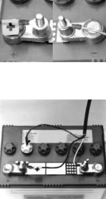
Table of Contents
Important Safety Instructions
General . . . . . . . . . . . . . . . . . . . . . . .1 AC Power Requirements . . . . . . . . . .1 Personal Precautions . . . . . . . . . . . . .1 Preparing to Charge . . . . . . . . . . . . .1 DC Connection Precautions . . . . . . . .1
Introduction
Items Included in System . . . . . . . . .2
Additional Items Needed . . . . . . . . . .2
Pump & Pipe Installation Instructions
Direct Discharge to Outside . . . . . .3,4 Hookup to Existing Discharge Pipe .5,6
Battery Instructions
Preparation of the Battery . . . . . . . . .7
Control Unit Hookup
Positioning the Control Unit . . . . . . . .8
Positioning the Float Switch . . . . . . . .8
Installing the Battery Fluid Sensor . . .8
Hooking Up the Pump . . . . . . . . . . . .8
Hooking Up the Battery . . . . . . . . . . .8
Understanding the Warning Lights and Alarms
Battery Fluid is Low . . . . . . . . . . . . . .9 Battery Problem . . . . . . . . . . . . . . . .9 Cable or Terminal Problem . . . . . .9,10 Replacing the Battery . . . . . . . . . . .10 Power Failure . . . . . . . . . . . . . . . . .10 Pump is Defective . . . . . . . . . . . . . .10 Pump was Activated . . . . . . . . . . . .10 Replacing the Pump . . . . . . . . . . . .11 Battery Power Level . . . . . . . . . . . . .11 Testing the Float Switch . . . . . . . . . .11
Parts & Service Information
Technical Support . . . . . . . . . . . . . .11
Important
Safety Instructions
General
Do not expose the control unit to rain or snow.
Pull the plug rather than the cord when disconnecting the control unit.
An extension cord should not be used unless absolutely necessary. If an extension cord must be used, be sure the plug has the same configuration as the plug on the control unit.
To reduce the risk of electric shock, unplug the control unit and disconnect the cables from the battery before attempting any maintenance or cleaning.
Do not disassemble the control unit. When service is required contact Glentronics technical support at (800) 991-0466, select option 3.
AC Power Requirements
The control unit must receive 115 volts AC +/- 5% from the AC outlet. Any voltage lower than this will cause the power failure alarm to activate. Lower voltages can be caused by utility company brown outs or heavy power draw from other appliances on the same circuit.
Personal Precautions
Wear eye protection and avoid touching your eyes while working near the battery.
If battery acid contacts skin or clothing, wash immediately with soap and water. If acid enters eye, immediately flood eye with running cold water for at least 10
minutes and get medical attention.
Never smoke or allow a spark or flame in the vicinity of the battery.
Remove personal metal items such as rings, bracelets, watches, etc. when working with a lead-acid battery.
Preparing to Charge
Charge only LEAD-ACID batteries with the Pro Series 2200 control unit. Do not use the control unit for charging dry-cell batteries that are most commonly used with home appliances.
Be sure the area around the battery is well-ventilated.
When cleaning or adding water to the battery, gas can be forcefully blown away by using a piece of cardboard or other nonmetallic material as a fan.
Clean the battery terminals. Be careful to keep corrosion from coming in contact with your eyes.
DC Connection Precautions
Connect and disconnect the battery cable rings only after removing the power cord from the electric outlet.
Never allow the rings to touch each other.
Coat the terminals with a thin coat of petroleum jelly to retard corrosion.
Attach the rings on the ends of the battery cables to the battery posts and secure them with wing nuts to insure a good connection.
Follow these steps when the battery is installed. A spark near the battery may cause a battery explosion. To reduce
the risk of a spark near the battery:
Check the polarity of the battery posts. The POSITIVE (+) battery post usually has a larger diameter than the NEGATIVE (-) post.
Connect the large ring on the POSITIVE (BLACK) wire from the control unit to the POSITIVE (+) post of the battery. Connect the small ring on the NEGATIVE (WHITE) wire from the control unit to the NEGATIVE (-) post of the battery.
When disconnecting the control unit, first disconnect the AC power cord, and then remove the rings from the battery terminals.
|
|
POSITIVE |
NEGATIVE |
POST HAS |
POST HAS |
LARGER |
SMALLER |
DIAMETER |
DIAMETER |
|
|
|
|
Page 1
Introduction
The Pro Series 2200 AC/DC backup sump pump system is battery-operated. It is designed as an emergency backup system to support your regular AC sump pump, and it will automatically begin pumping if your main AC pump fails. Should any malfunction or emergency occur that involves the sump pump, the battery, or the AC power, your Pro Series 2200 battery backup sump pump system will sound an alarm and indicate the nature of the problem and the solutions by means of a lighted display on the control panel.
If the main pump breaks or is unable to keep up with all the incoming water, the Pro Series pump is capable of running without discharging the battery as long as the AC power is on.
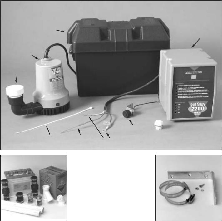
The Pro Series 2200 Battery Backup Sump Pump System includes:
1 Control unit with a float switch and a battery fluid level sensor
1 Pump with 11⁄2" PVC pipe adapter 1 Battery box with safety strap
1 Plastic wire tie for mounting the float switch
1 Battery cap with a hole to accommodate the fluid sensor
You will also need to supply:
A Pro Series 2200 Standby Battery (A maintenance-free battery is not recommended)
11⁄2" PVC pipe and fittings
PVC cement and primer
A rubber union with hose clamps or a "Y" connector and two (2) check valves depending on the installation method you use
Six (6) quarts of 1.265 specific gravity battery acid
BATTERY
BOX
CONTROL UNIT
PUMP
PIPE
ADAPTER
FLOAT
SWITCH CAP
WIRE TIE |
FLUID |
BATTERY |
|
SENSOR |
|||
|
|||
|
CABLES |
||
|
|
For narrow sump pits you will need some additional parts:
An "L" bracket at least 6 inches long. (Preferably one that will not rust.)
Two (2) stainless steel hose clamps
One (1) stainless steel screw (#8-32 x 3⁄4"), a matching washer & nut
Page 2
Pump & Pipe Installation Instructions
(Direct Discharge to Outside)
There are two basic methods that can be used to install the pump, (A) a direct discharge to the outside of the building, or (B) a hookup to an existing discharge pipe.
Whenever possible, install your Pro Series 2200 backup sump pump with a direct discharge to the outdoors. By using this method, there will always be an outlet for the water from the sump. During times of very heavy rain, many storm sewers fill up. If your pump is trying to discharge water into a full sewer, there is nowhere for the water to go. This defeats the purpose of the backup system. By discharging directly outdoors, there is always an outlet for the water that is pumped out of the sump.
There are two options for installing your sump pump with a direct discharge to the outside. If you have a sump pit wide enough to place the backup pump next to the main pump, use Method A. If your sump pit is too narrow, the pump may be mounted above the main pump. In this instance use the instructions for Method Aa.
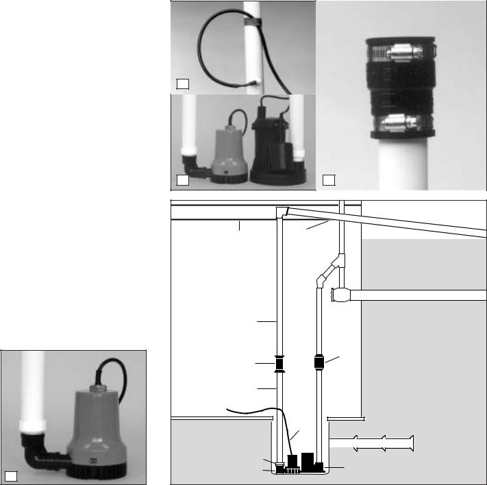
METHOD A: DIRECT DISCHARGE TO THE OUTSIDE OF THE BUILDING (Diagram A)
1.Cut a four-foot (4’) piece of 11/2" rigid PVC pipe and cement it to the threaded fitting that is attached to the elbow on the pump.
2.Secure the pump wire so that the plug on the end will not fall into the sump. Attach the wire to the pipe with a piece of tape.
3.Place the pump with the 4’ PVC pipe attachment on the bottom of the sump floor next to the main AC pump. Do not mount the pump to any existing pipes...it should be placed on the floor of the sump. A brick may be placed under the pump if there are rocks or other debris on the sump floor.
4.Attach a rubber union (sold separately) to the top of the 11/2" pipe. This will allow the pump to be removed easily, should the need arise.
The path of the rest of the pipe and the details of each installation will vary. Using sound plumbing practices, try to route the discharge pipe to an exterior wall via the shortest path with the fewest turns. The pipe section exiting the building should be on a downward slope so that the water in the pipe will exit outside rather than return to the sump. Extend the discharge pipe outside the building as far as possible to avoid the return of discharged water to the sump.
Be sure to seal the hole in the wall where the pipe exits and cement or clamp all connections securely to prevent leaking.
No check valve is needed with this method of installation, as long as you use less than 20 feet of pipe.
1
2 |
|
|
|
3 |
4 |
|
|
FLOOR |
SLOPE |
|
|
JOIST |
PIPE |
|
|
|
DOWN |
|
|
RIGID |
|
|
|
1-1/2" |
|
|
|
PVC PIPE |
|
|
|
|
CHECK |
|
|
RUBBER |
VALVE |
|
|
|
|
||
UNION |
|
|
|
RIGID |
|
|
|
1-1/2" |
|
|
|
PVC PIPE |
|
|
|
|
PUMP |
|
|
|
WIRE |
|
|
|
DRAIN |
TILE |
|
PIPE ADAPTER |
MAIN AC PUMP |
||
PRO SERIES PUMP |
|||
|
|
||
Page 3
Diagram A
 Loading...