


 Loading...
Translation of the original instructions
 TC 110
Electronic Drive Unit
Operating Instructions
PT 0204 BEN/H (1008)
EN

Table of contents
Table of contents
1 |
About this manual. . . . . . . . . . . . . . . . . . . . . . . . . . . . . . . . . . . . . . . . . . . . . . . |
3 |
|
|
1.1 |
Validity. . . . . . . . . . . . . . . . . . . . . . . . . . . . . . . . . . . . . . . . . . . . . . . . . . . . . |
3 |
|
1.2 |
Conventions . . . . . . . . . . . . . . . . . . . . . . . . . . . . . . . . . . . . . . . . . . . . . . . . |
3 |
2 |
Safety . . . . . . . . . . . . . . . . . . . . . . . . . . . . . . . . . . . . . . . . . . . . . . . . . . . . . . . . . |
4 |
|
2.1 Safety precautions . . . . . . . . . . . . . . . . . . . . . . . . . . . . . . . . . . . . . . . . . . . 4 2.2 Proper use. . . . . . . . . . . . . . . . . . . . . . . . . . . . . . . . . . . . . . . . . . . . . . . . . . 5 2.3 Improper use. . . . . . . . . . . . . . . . . . . . . . . . . . . . . . . . . . . . . . . . . . . . . . . . 5
3 |
Product description . . . . . . . . . . . . . . . . . . . . . . . . . . . . . . . . . . . . . . . . . . . . . . |
6 |
|
|
3.1 |
Product identification . . . . . . . . . . . . . . . . . . . . . . . . . . . . . . . . . . . . . . . . . |
6 |
|
3.2 |
Range of application . . . . . . . . . . . . . . . . . . . . . . . . . . . . . . . . . . . . . . . . . . |
6 |
|
3.3 |
Function . . . . . . . . . . . . . . . . . . . . . . . . . . . . . . . . . . . . . . . . . . . . . . . . . . . |
6 |
|
3.4 |
General connection description . . . . . . . . . . . . . . . . . . . . . . . . . . . . . . . . . |
6 |
4 Connections diagram . . . . . . . . . . . . . . . . . . . . . . . . . . . . . . . . . . . . . . . . . . . . 7 5 Connection "X3" . . . . . . . . . . . . . . . . . . . . . . . . . . . . . . . . . . . . . . . . . . . . . . . . 8
5.1 Pin assignment . . . . . . . . . . . . . . . . . . . . . . . . . . . . . . . . . . . . . . . . . . . . . . 8 5.2 Operation via "X3" connection . . . . . . . . . . . . . . . . . . . . . . . . . . . . . . . . . . . 8
6 The Pfeiffer Vacuum parameter set . . . . . . . . . . . . . . . . . . . . . . . . . . . . . . . . |
12 |
6.1 General . . . . . . . . . . . . . . . . . . . . . . . . . . . . . . . . . . . . . . . . . . . . . . . . . . . .12 6.2 Parameter overview . . . . . . . . . . . . . . . . . . . . . . . . . . . . . . . . . . . . . . . . . .12 6.3 Configuring the connections . . . . . . . . . . . . . . . . . . . . . . . . . . . . . . . . . . . .15 6.4 Operation with the Pfeiffer Vacuum parameter set . . . . . . . . . . . . . . . . . .17
7 Pfeiffer Vacuum Protocol for "RS485" . . . . . . . . . . . . . . . . . . . . . . . . . . . . . . |
23 |
7.1 Telegram frame . . . . . . . . . . . . . . . . . . . . . . . . . . . . . . . . . . . . . . . . . . . . . 23 7.2 Telegrams . . . . . . . . . . . . . . . . . . . . . . . . . . . . . . . . . . . . . . . . . . . . . . . . . 23 7.3 Applied data types . . . . . . . . . . . . . . . . . . . . . . . . . . . . . . . . . . . . . . . . . . 24
8 |
Malfunctions . . . . . . . . . . . . . . . . . . . . . . . . . . . . . . . . . . . . . . . . . . . . . . . . . . |
25 |
|
|
8.1 |
General . . . . . . . . . . . . . . . . . . . . . . . . . . . . . . . . . . . . . . . . . . . . . . . . . . . |
25 |
|
8.2 |
Operating mode display via LED . . . . . . . . . . . . . . . . . . . . . . . . . . . . . . . . |
25 |
|
8.3 |
Error codes . . . . . . . . . . . . . . . . . . . . . . . . . . . . . . . . . . . . . . . . . . . . . . . . |
25 |
9 |
Accessories. . . . . . . . . . . . . . . . . . . . . . . . . . . . . . . . . . . . . . . . . . . . . . . . . . . . |
27 |
|
|
Declaration of conformity . . . . . . . . . . . . . . . . . . . . . . . . . . . . . . . . . . . . . . . . |
28 |
|
2
About this manual
1About this manual
1.1 Validity
This operating manual is for customers of Pfeiffer Vacuum. It describes the functioning of the designated product and provides the most important information for safe use of the unit. The description follows applicable EU guidelines. All information provided in this operating manual refer to the current state of the product's development. The documentation remains valid as long as the customer does not make any changes to the product.
Up-to-date operating instructions can also be downloaded from
www.pfeiffer-vacuum.net.
1.2 Conventions
Safety instructions The safety instructions in Pfeiffer Vacuum operating manuals are the result of risk evaluations and hazard analyses and are oriented on international certification standards as specified by UL, CSA, ANSI Z-535, SEMI S1, ISO 3864 and DIN 4844. In this document, the following hazard levels and information are considered:
CAUTION
Possible danger
Injuries or property damages can occur.
Pictograph definitions
Instructions in the text
Abbreviations used
NOTE
Command or note
Command to perform an action or information about properties, the disregarding of which may result in damage to the product.
Warning of a displayed source of danger in connection with operation of the unit or equipment.
Command to perform an action or task associated with a source of danger, the disregarding of which may result in serious accidents.
Work instruction: here you have to do something.
DCU:Display and operating unit
HPU:Handheld programming unit
TC:Electronic drive unit for turbopump
TPS:Mains pack
DI / DO:Digital input / digital output
AI / AO:Analog input / analog output
f:Rotation speed (derivated from frequency in Hz)
[P:000]:Parameter of the electronic drive unit with number
3
Safety
2Safety
2.1 Safety precautions
NOTE
Duty to inform
Each person involved in the installation or operation of the unit must read and observe the safety-related parts of these operating instuctions.
The operator is obligated to make operating personnel aware of dangers originating from the unit or the entire system.
WARNING
Danger - Electrical installation
Safe operation after installation is the responsibility of the operator.
Do not independently modify or change the pump and electrical equipment.
Make sure that the system is integrated in an emergency off safety circuit.
Consult Pfeiffer Vacuum for special requirements.
WARNING
Danger of electric shock
In case of defect, the parts connected to the power supply are under voltage.
Always keep the mains connection freely accessible so you can disconnect it at any time.
•Power supply: The turbopump power supply must apply to the requirements of double insulation between mains input voltage and operating voltage according to the regulations of IEC 61010 and IEC 60950. Therefore Pfeiffer Vacuum recommends to use exclusively original-power packs and -accessories. Only in this case Pfeiffer Vacuum is able to guarantee the compliance of the European and North American guidelines.
•Observe all safety and accident prevention regulations.
•A safe connection to the protective earthing conductor (PE) is recommended (protection class III).
•Regularly check the proper observance off all safety measures.
•Before carrying out any work disconnect the unit and all associated installations safely from the mains.
•Do not loosen any plug connection during operations.
•The unit has been accredited with protection class IP 30. When installing into ambient conditions, which afford other protection classes, the necessary measures must be taken.
•Keep leads and cables well away from hot surfaces (> 70 °C).
•Only seperate the pump and the electronic drive unit from each other after disconnecting the supply voltage and the complete standstill of the pump.
4
Safety
2.2 Proper use
NOTE
CE conformity
The manufacturer's declaration becomes invalid if the operator modifies the original product or installs additional components!
Following installation into a plant and before commissioning, the operator must check the entire system for compliance with the valid EU directives and reassess it accordingly.
•The electronic drive unit TC 110 operates designated Pfeiffer Vacuum turbopumps and their accessories.
2.3 Improper use
Improper use will cause all claims for liability and warranties to be forfeited. Improper use is deemed to be all use for purposes deviating from those mentioned above, especially:
•The use of accessories, which are not named in this manual.
•The operation of the devices in potentially radioactive areas.
warranty seal |
NOTE |
Closure seal
The product is sealed at the factory. Damaging or removal of a closure seal leads to the loss of liability and warranty entitlements.
Do not open the product within its warranty period!
For process-related shorter maintenance intervals please contact the Pfeiffer Vacuum Service.
5
Product description
3Product description
3.1 Product identification
Product features |
The electronic drive unit TC 110 is an integrated component of the turbopump. It's |
|
|
purpose is to drive, monitor and control the entire pump. |
|
|
|
|
|
Characteristics |
TC 110 |
|
Connection voltage TC |
24 V DC ± 5 % |
|
|
|
|
Connection panel |
Standard (X3) |
|
|
|
|
Turbopump HiPace |
10, 60, 80, 300 |
|
|
|
To correctly identify the product when communicating with Pfeiffer Vacuum, always have the information from the rating plate available.
3.2 Range of application
Pfeiffer Vacuum electronic drive units TC 110 must be installed and operated in the following ambient conditions.
Installation location |
weather protected (indoors) |
|
|
Protection category |
IP 30 |
|
|
Protection class |
III |
|
|
Temperature |
+5 °C to +40 °C (up to +35 °C with air cooling) |
|
|
Relative humidity |
max. 80 %, at T ≤ 31 °C, up to max. 50% at T ≤ 40 °C |
|
|
Atmospheric pressure: |
77 kPa - 106 kPa |
|
|
Installation altitude |
2000 m max. |
|
|
Degree of pollution |
2 |
|
|
Overvoltage category |
II |
|
|
3.3 Function
|
d |
c |
|
h |
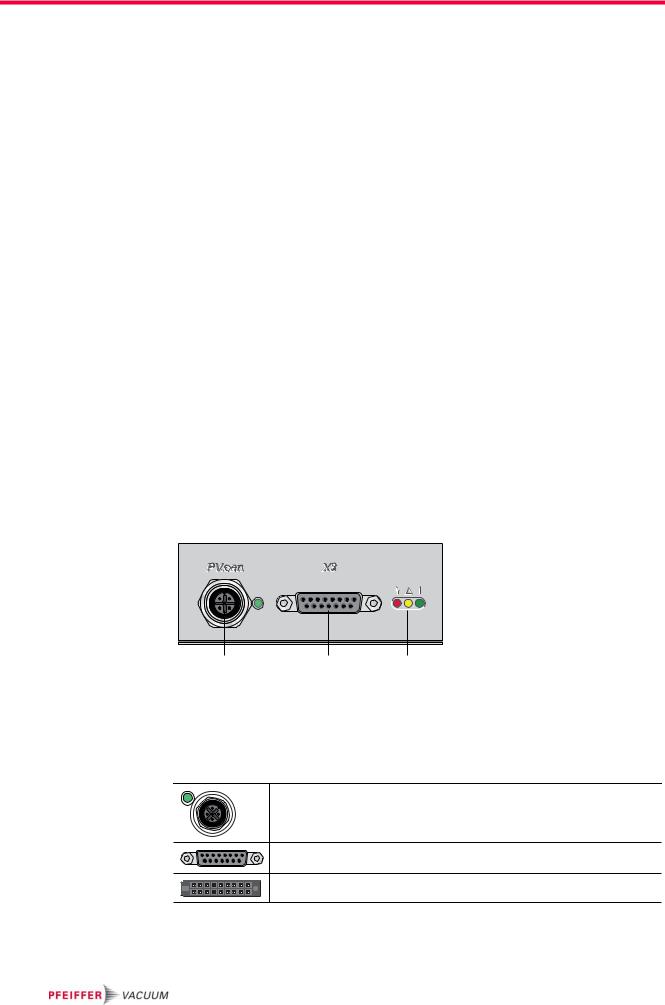
Fig. 1: Standard panel for the TC 110 |
|
|
||
c |
Connection "X3" |
|
h |
LED "Operating display" |
dService connection "PV.can"
3.4General connection description
PV.can1
M12 casing socket with screw coupling and LED for Pfeiffer Vacuum Service purposes.
X3
D-sub 15 pole female socket for the connection of a remote control.
Casing socket on the rear side of the electronic drive unit for the connection
to the turbopump.
1. The connection "PV.can" serves to service purposes exclusively.
6

7
110 TC the of assignment and diagram Connections 2: .Fig
TC 110
X3
|
|
DI Remote Priority |
2 |
|
|
|||||||||
|
|
|
|
|
|
|
|
|
DI1 |
3 |
|
|
||
|
|
|
|
|
|
|
|
|
DI2 |
4 |
|
|
||
|
DI Pumping station |
5 |
|
|
||||||||||
|
|
|
|
DI Standby |
6 |
|
|
|||||||
|
|
|
24 VDC* (V+) |
7 |
|
|
||||||||
|
|
|
|
|
|
|
|
|
|
|
|
|
||
|
|
|
Accessory A1 |
10 |
|
|
||||||||
|
|
|
Accessory B1 |
11 |
|
|
||||||||
|
|
|
|
|
|
|
DO1 |
8 |
|
|
||||
|
|
|
|
|
|
|
DO2 |
9 |
|
|
||||
|
|
|
|
|
|
|
AO1 |
12 |
|
|
||||
|
|
|
|
|
RS 485 D+ |
13 |
|
|
||||||
|
|
|
|
|
RS 485 D- |
14 |
|
|
||||||
|
|
|
|
|
|
|
|
|
|
|
15 |
|
|
|
|
|
|
|
|
|
|
|
|
|
|
|
|
||
|
|
|
|
|
|
|
+UB |
1 |
|
|
||||
|
|
|
|
|
|
|
|
|
PE |
|
|
|
|
|
|
|
|
|
|
|
|
|
|
|
|
|
|
||
|
|
|
|
|
|
|
|
|
|
|
|
|
|
|
8
15
9
1
Connection cable |
Connection cable TC 110 - TPS/DCU |
External connection |
|
TC 110 - TPS/DCU, RS485 |
with accessory ports, RS485 |
||
|
X3
2 |
S2 |
2 |
3 |
|
3 |
4 |
|
4 |
5 |
S1 |
5 |
6 |
|
6 |
7 |
|
7 |
10 |
|
10 |
11 |
|
11 |
8 |
|
8 |
9 |
|
9 |
12 |
|
12 |
13 |
|
13 |
14 |
|
14 |
15 |
|
15 |
1 |
|
1 |
+U |
|
PE |
RS485 + |
VDC*24 |
|
RS485 - |
n.c. |
+U |
B |
|
|
|
|
|
|
|
B |
1 |
2 |
3 |
1 |
2 |
3 |
4 |
5 |
1 |
|
|
2 |
|
|
1 |
2 |
|
|
|
|
|
|
|
|
|
||
1 |
|
|
3 |
|
4 |
3 |
|
1 |
|
|
|
|
|
|
|
X3 |
|
|
|
|
|
|
|
X3 |
contact |
|
S2 |
|
|
|
|
|
|
2 |
|
|
|
|
|
|
|
|
|
|
3 |
|
mA / |
|
|
|
|
|
|
|
|
4 |
|
. 6 |
Fa n |
|
|
|
|
|
|
|
|
max |
||
S1 |
|
|
|
|
|
|
5 |
|
Vent i ng |
|
|
|
|
|
|
|
|
|
|||
|
|
|
|
|
|
|
current |
v a lve |
||
|
|
|
|
|
|
|
6 |
|
Rel a y |
|
|
|
|
|
|
|
|
|
|
||
|
|
1 |
|
4 |
|
|
7 |
|
Contact |
|
|
|
3 |
Acc . A1 3 |
|
1 |
|
|
|
Fa n |
|
|
|
|
|
|
|
|
||||
|
|
4 |
|
|
|
|
|
|||
|
|
|
|
|
|
|
|
|
Vent i ng |
|
|
|
|
|
|
|
|
|
|
|
v a lve |
|
|
1 |
|
4 |
|
|
10 |
|
24 VDC / max. 200 mA |
Rel a y |
|
|
|
|
|
|
|
|
|
||
|
|
3 |
|
|
|
11 |
|
|
|
|
|
|
Acc . B1 3 |
|
1 |
|
|
24 VDC / max. 200 mA |
|
||
|
|
4 |
|
|
8 |
|
|
|
||
|
|
|
|
|
|
|
24 VDC / max. 50mA |
|
||
|
|
|
|
|
|
|
9 |
|
24 VDC / max. 50mA |
|
|
|
|
|
|
|
|
12 |
|
|
|
|
|
|
|
|
|
|
13 |
|
0 - 10 VDC |
|
|
|
|
|
|
|
|
14 |
|
= 0 - 100 % *fend |
|
|
|
|
|
|
|
|
|
R ≥ 10kΩ |
|
|
|
|
|
|
|
|
|
|
|
|
|
|
|
|
|
|
|
|
15 |
|
|
|
|
|
|
|
|
|
|
1 |
|
+24 VDC / 4,6 - 6,3 A ± 5 % |
|
|
|
|
|
|
|
|
|
|
PE |
|
|
|
|
485RS+ |
VDC*24 |
|
485RS- |
|
|
|
+UB |
|
PE |
|
|
|
c.n. |
|
PE |
|||
2 |
3 |
|
1 |
2 |
3 |
4 |
5 |
|
|
|
2 |
|
|
|
|
1 |
2 |
|
|
|
|
|
|
|
|
|
|
|
|
|
||
|
|
3 |
|
|
4 |
3 |
|
|
|
|
|
|
|
|
|
|
|
|
|
||
X2 |
X1 |
Mains input / |
|
Power supply |
|||
|
|
2 |
90 - 132 / |
|
1 |
||
185 - 265 |
||
|
VAC |
|
3 |
|
TPS 110 / 180
DCU 110 / 180
DC in |
RS485 |
DC in |
RS485 |
TPS 110 / 180 and DCU 002 / HPU 001 |
TPS 110 / 180 and DCU 002 / HPU 001 |
||
|
or |
|
or |
|
DCU 110 / 180 |
|
DCU 110 / 180 |
diagram Connections 4
diagram Connections

Connection "X3"
5Connection "X3"
Remote control options and voltage supply are provided via the 15-pole D-Sub connector with the designation ”X3“ on the TC 110.
Shielded connectors and cables must be used.
The following information display the factory setting. Configuration is possible using the Pfeiffer Vacuum parameter set.
NOTE
Danger of the drive unit beeing destroyed
Cutting the plug connection "X3" can lead to the destruction of the electronic drive unit, when the power supply is still switched on.
Before pulling the connector "X3" necessarily disconnect the power supply.
Switch off the power supply unit.
5.1Pin assignment
Pin |
Function |
Designation factory settings |
1 |
+24 VDC input |
Voltage supply for the electronic drive unit |
|
|
|
2 |
DI Remote priority |
Control via interface "X3"; open: off; |
|
|
V+: set and priority over other digital inputs |
|
|
|
3 |
DI1 |
Enable venting; open: off; V+: on |
|
|
|
4 |
DI2 |
Heating; open: off; V+: on |
|
|
|
5 |
DI Pumping station |
open: off; V+: on and error acknowledgement |
|
|
|
6 |
DI Standby |
Standby rotation speed; open: off; V+: on |
|
DI Error acknowledgement |
Error acknowledgement: V+ pulse (500 - 2000 ms) |
|
|
|
7 |
+24 VDC* output (V+) |
Reference voltage for all digital inputs |
|
|
|
8 |
DO1 |
GND: no; V+: yes (Imax = 50 mA/24 V) |
9 |
DO2 |
GND: no; V+: yes (Imax = 50 mA/24 V) |
10 |
Accessory output A1 |
open: off; V+: on |
|
|
|
11 |
Accessory output B1 |
open: off; V+: on |
|
|
|
12 |
AO1 |
Actual rotation speed; 0-10 VDC is equivalent to 0-100%; |
|
|
RL > 10 kΩ |
13 |
RS485 |
D+ |
|
|
|
14 |
RS485 |
D- |
|
|
|
15 |
Ground (GND) |
Ground connection for the elctronic drive unit; |
|
|
Reference ground for all digital inputs and all outputs |
|
|
|
5.2 Operation via "X3" connection
Voltage supply |
+24 VDC Input / Pin 1 |
|
The electrical connection at "X3" is carried out via connecting cables of the Pfeiffer |
|
Vacuum accessories program or by customized configuration on Pin 1 and Pin 15. |
|
+24 VDC* Output / Pin 7 |
|
Inputs 2 - 6 are activated by connecting them with +24 VDC to Pin 7 (active high). |
|
They can also be activated via an external PLC. The functions are deactivated by |
|
"PLC high level" and by "PLC low level". |
|
• PLC high level: +13 V to +33 V |
|
• PLC low level: -33 V to +7 V |
|
• Ri: 7 kΩ |
8

|
|
Connection "X3" |
|
|
|
|
|
|
Inputs |
The digital inputs at connection "X3" are used to connect various functions of the |
|
|
electronic drive unit. Functions are assigned to the inputs DI1 - DI2 ex factory. |
|
|
These can be configured via interface RS485 and the Pfeiffer Vacuum parameter |
|
|
set. |
|
|
DI Remote priority / Pin 2 |
|
|
V+ : The connection "X3" has operation priority over all other digital inputs. |
|
|
open: Remote priority inactive |
|
|
DI1 (Enable venting) / Pin 3 |
|
|
V+ : Venting is enabled (venting according to venting mode) |
|
|
open: Venting locked (no venting is performed) |
|
|
DI2 (Heating) / Pin 4 |
|
|
V+ : |
Heating on |
|
open: Heating off |
|
|
DI Pumping station / Pin 5 |
|
|
The turbopumps is placed in operation and connected pumping station compo- |
|
|
nents (e.g. backing pump, venting valve, air cooling unit) are triggered. Any ongo- |
|
|
ing error messages are reset when their cause has been eliminated. |
|
|
V+ : Malfunction acknowledgement and pumping station on |
|
|
open: Pumping station off |
|
|
DI Standby - Error acknowledgement / Pin 6 |
|
|
In standby mode, the turbopump operates at a specified rotor speed < nominal ro- |
|
|
tation speed. Factory setting and recommended operation are 66.7 % of the nomi- |
|
|
nal rotation speed. |
|
|
V+ : |
Standby activated |
|
V+ : |
Reset ongoing error messages when cause has been eliminated with a pulse |
|
of 500 - 2000 ms duration |
|
|
open: Standby off, operation at nominal rotation speed |
|
Outputs |
The digital outputs at the connection "X3" can be loaded with a maximum of 24 V |
|
|
/ 50 mA per output. All outputs listed below are configurable by the Pfeiffer Vacu- |
|
|
um parameter set via interface RS485 (description related to factory settings). |
|
DO1 (Rotation speed switch point attained) / Pin 8
Active high after the rotation speed switch point is attained. Rotation speed switch point 1 is factory-set to 80% of the nominal rotation speed. It can, for example, be used for a "pump operational" message.
DO2 (No errors) / Pin 9
When the supply voltage has been established, digital output DO2 permanently outputs 24 VDC which means "no errors". Active low in case of error (collective error message).
Accessory outputs / Pin 10 and Pin 11
The accessory outputs can be loaded with a maximum of 24 V / 200 mA per output.
Additional functions can be assigned to the accessory inputs and outputs via DCU,
HPU or PC. Works settings:
• Accessory output A1: A connected air cooling unit is activated.
9
Loading...