


OPERATING INSTRUCTIONS
OME 40 M/MR, OME 40 C/CR
Oil Mist Eliminator
EN
Translation of the original instructions
PD 0053 BEN/D (1701)

Table of contents
Table of contents
1 About this manual. . . . . . . . . . . . . . . . . . . . . . . . . . . . . . . . . . . . . . . . . . . . . . . 3
2 Safety . . . . . . . . . . . . . . . . . . . . . . . . . . . . . . . . . . . . . . . . . . . . . . . . . . . . . . . . . 5
3 Transport and storage. . . . . . . . . . . . . . . . . . . . . . . . . . . . . . . . . . . . . . . . . . . . 6
4 Product description. . . . . . . . . . . . . . . . . . . . . . . . . . . . . . . . . . . . . . . . . . . . . . 6
5 Installation . . . . . . . . . . . . . . . . . . . . . . . . . . . . . . . . . . . . . . . . . . . . . . . . . . . . . 8
6 Operation . . . . . . . . . . . . . . . . . . . . . . . . . . . . . . . . . . . . . . . . . . . . . . . . . . . . . 13
7 Maintenance. . . . . . . . . . . . . . . . . . . . . . . . . . . . . . . . . . . . . . . . . . . . . . . . . . . 14
8 Service . . . . . . . . . . . . . . . . . . . . . . . . . . . . . . . . . . . . . . . . . . . . . . . . . . . . . . . 19
9 Accessories . . . . . . . . . . . . . . . . . . . . . . . . . . . . . . . . . . . . . . . . . . . . . . . . . . . 19
10 Technical data and dimensions . . . . . . . . . . . . . . . . . . . . . . . . . . . . . . . . . . . 20
11 Spare parts. . . . . . . . . . . . . . . . . . . . . . . . . . . . . . . . . . . . . . . . . . . . . . . . . . . . 21
12 Disposal . . . . . . . . . . . . . . . . . . . . . . . . . . . . . . . . . . . . . . . . . . . . . . . . . . . . . . 23
1.1 Validity. . . . . . . . . . . . . . . . . . . . . . . . . . . . . . . . . . . . . . . . . . . . . . . . . . . . . 3
1.2 Conventions . . . . . . . . . . . . . . . . . . . . . . . . . . . . . . . . . . . . . . . . . . . . . . . . 3
2.1 Safety precautions . . . . . . . . . . . . . . . . . . . . . . . . . . . . . . . . . . . . . . . . . . . 5
2.2 Proper use . . . . . . . . . . . . . . . . . . . . . . . . . . . . . . . . . . . . . . . . . . . . . . . . . 5
2.3 Improper use. . . . . . . . . . . . . . . . . . . . . . . . . . . . . . . . . . . . . . . . . . . . . . . . 5
3.1 Storage . . . . . . . . . . . . . . . . . . . . . . . . . . . . . . . . . . . . . . . . . . . . . . . . . . . . 6
4.1 Product identification. . . . . . . . . . . . . . . . . . . . . . . . . . . . . . . . . . . . . . . . . . 6
4.2 Function . . . . . . . . . . . . . . . . . . . . . . . . . . . . . . . . . . . . . . . . . . . . . . . . . . . 7
5.1 Assembly . . . . . . . . . . . . . . . . . . . . . . . . . . . . . . . . . . . . . . . . . . . . . . . . . . 8
5.2 Installing the operating fluid return line . . . . . . . . . . . . . . . . . . . . . . . . . . . . 9
5.3 Installing the operating fluid return line . . . . . . . . . . . . . . . . . . . . . . . . . . . 10
5.4 Installing the saturation indicator optically/electrical (option) . . . . . . . . . . 12
7.1 Draining the operating fluid . . . . . . . . . . . . . . . . . . . . . . . . . . . . . . . . . . . . 14
7.2 Changing the filter element . . . . . . . . . . . . . . . . . . . . . . . . . . . . . . . . . . . . 16
7.3 Cleaning the operating fluid return line . . . . . . . . . . . . . . . . . . . . . . . . . . . 18
10.1 Technical data. . . . . . . . . . . . . . . . . . . . . . . . . . . . . . . . . . . . . . . . . . . . . . 20
10.2 Dimensions . . . . . . . . . . . . . . . . . . . . . . . . . . . . . . . . . . . . . . . . . . . . . . . . 20
11.1 Spare parts packages . . . . . . . . . . . . . . . . . . . . . . . . . . . . . . . . . . . . . . . . 21
2

About this manual
1 About this manual
1.1 Validity
This operating manual is for customers of Pfeiffer Vacuum. It describes the functioning
of the designated product and provides the most important information for safe use of
the unit. The description follows applicable EU guidelines. All information provided in this
operating manual refers to the current state of the product's development. The documentation remains valid as long as the customer does not make any changes to the product.
Up-to-date operating instructions can also be downloaded from
www.pfeiffer-vacuum.com.
1.2 Conventions
Safety instructions The safety instructions in Pfeiffer Vacuum operating instructions are the result of risk
evaluations and hazard analyses and are oriented on international certification standards as specified by UL, CSA, ANSI Z-535, SEMI S1, ISO 3864 and DIN 4844. In this
document, the following hazard levels and information are considered:
DANGER
Imminent danger
Indicates an imminent hazardous situation that will result in death or serious injury.
WARNING
Possibly imminent danger
Indicates an imminent hazardous situation that can result in death or serious injury.
CAUTION
Possibly imminent danger
Indicates an imminent hazardous situation that can result in minor or moderate injury.
NOTICE
Command or note
Command to perform an action or information about properties, the disregarding of
which may result in damage to the product.
3

About this manual
Pictographs
Instructions in the
Work instruction: here you have to do something.
Prohibition of an action to avoid any risk of accidents, the disregarding
of which may result in serious accidents
Warning of a displayed source of danger in connection with operation of
the unit or equipment
Command to perform an action or task associated with a source of danger, the disregarding of which may result in serious accidents
Important information about the product or this document
text
Abbreviations OME: Oil mist eliminator
OME_ R: Oil mist separator with return unit
C version: Corrosive gas version
Symbols used The following symbols are used consistently throughout in all illustrations:
V
Vacuum flange
Exhaust flange
X
Connection flange OME
4

2Safety
2.1 Safety precautions
Duty to inform
Each person involved in the installation or operation of the unit must read and observe
the safety-related parts of these operating instuctions.
The operator is obligated to make operating personnel aware of dangers originating
from the unit or the entire system.
Before carrying out any work read and observe the operating and safety instructions
of the pumping station and the individual components.
Observe the safety and accident prevention regulations.
Check regularly that all safety precautions are being complied with.
When returning the components to us please note the instructions in the Service sec-
tion.
2.2 Proper use
Only use the oil mist eliminator to filter oil mist from the gas flow of rotary vane pumps.
Simply mount the OME onto the exhaust port of rotary vane pumps.
Use the OME in accordance with the corresponding approved pumping speed.
Safety
2.3 Improper use
Improper use will cause all claims for liability and warranties to be forfeited. Improper use
is defined as usage for purposes deviating from those mentioned above, especially:
connection to pumps or units which are not suitable for this purpose according to their
operating instructions
connection to units which have exposed voltage-carrying parts
use of accessories or spare parts, which are not named in this manual
pumping-off of gases and vapors that may be prone to polymerization or may resinify
the filter inserts
5

Transport and storage
3 Transport and storage
3.1 Storage
The OME should be stored dry and protected from moisture. The filter elements can absorb moisture, and the lubrication properties of the oil and hence the end pressure can
be negatively influenced in pumps with an oil return unit.
4 Product description
4.1 Product identification
To correctly identify the product when communicating with Pfeiffer Vacuum, always have
the information from the rating plate available.
● Model and model number
● Date of manufacture
Variants
Range of application
Type Versions Characteristics
OME 40 M Standard model
OME 40 MR Version with operating fluid return
line to the intake side
OME 40 C Corrosive gas model for pump
model C/MC
OME 40 CR Corrosive gas model with operat-
ing fluid return line; applicable for
pump model C/MC
preinstalled
● Sight glass 13 of PCTFE
● Filter elements 14 of sintered carbon
● Integral leak rate: < 1 · 10
● Sight glass 13 of PCTFE
● Filter elements 14 of sintered carbon
● Integral leak rate: < 1 ·10
-7
Pa m3/s
-7
Pa m3/s
The operating fluid return unit operates without auxiliary power and is capable of operating in the final vacuum range of 800 hPa intake pressure (at 1000 hPa air pressure).
Moreover, its operation is not affected by rotational speed, gas ballast application or builtup exhaust-side pressure. During dynamic pump-down cycles such as load lock applications involving small volumes extended pump-down times are to be expected for intake
pressures < 5 · 10
-2
hPa.
6

4.2 Function
Product description
The oil mist filter is mounted on the exhaust port of rotary vane pumps. It filters oil mist
particles from the conveyed gas flow and thus reduces the escape of operating fluid mist.
The filter elements are installed in a corrosion-resistant aluminum casing and consist of
a cylindrical filter made from glass/polyester fleece in the standard and helium-tight versions, or from sintered carbon in the corrosive gas version. A baffle is also fitted over the
filter insert. An integrated pressure relief valve opens when the filter elements are excessively contaminated, so that the maximum operating pressure of 1500 hPa (absolute) is
not exceeded. The volume of filtered operating fluid can be viewed through a sight glass
and drained via a drain screw.
To return the filtered operating fluid from the OME into the pump without interrupting the
pump operation, an operating fluid return (optional) can be used.
V
110
24
10 0
Operating fluid return
line (option)
15
55
13
Fig. 1: Duo 35/65 with oil mist filter OME 40 MR
13 Sight glass
15 Filter element saturation
indicator
24 Interchangeable flange
55 Operating fluid drain
screw
100 Oil mist filter
110 Operating fluid return line
If the operating fluid accumulated in the OME reaches a specified level, a float valve
opens and the operating fluid is channeled via intake pressure back into the rotary vane
pump´s intake side. To avoid impairing the function of the pump, any process-related
condensate in the oil sump, must be drained as necessary.
The use of the operating fluid return increases the operational safety of the pump and
reduces the maintenance requirements.
7
Installation
5 Installation
5.1 Assembly
To install the ONF in a vacuum system, flange connections are provided on the input side
and output side.
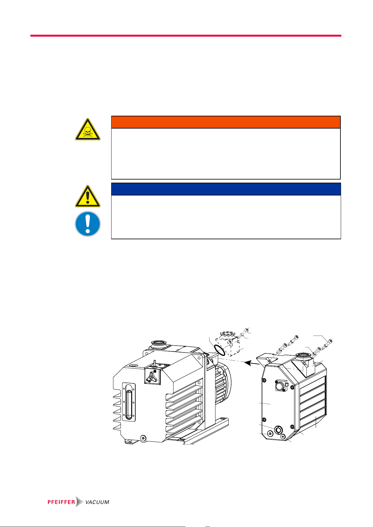
If gases are being pumped that are not permitted to enter the atmosphere, a pressureless exhaust line must be connected to the exhaust flange.
WARNING
Poisonous substances exit from the exhaust!
There is a poisoning hazard from discharged gases or vapors that can be hazardous
and/or polluting during use.
Install and run the exhaust line so that overpressure cannot build up inside it.
Follow the vacuum pump installation instructions in the respective operating instruc-
tions.
NOTICE
Vacuum component
Dirt and damage impair the function of the vacuum component.
When handling vacuum components, ensure that they are kept clean and are protect-
ed against damage.
Ensure that the connection flange is clean, dry and free of grease.
Turn off the vacuum pump, vent to atmospheric pressure and allow to cool.
Unscrew screws 46 and dismantle the interchangeable flange 24 on the exhaust side
of the rotary vane pump.
Fit interchangeable flange 24 to the exhaust side of the OME, being careful with O-
ring 60 and spring washers 57.
Mount the OME on the pump in place of the interchangeable flange 24.
Lay exhaust line from the OME sloping downward so that no condensate can flow
back.
– If an air trap is created in the system, then a device for draining condensation water
must be provided at the lowest point.
60
24
57
46
46
(10 Nm)
57
24
2
13/62
54/63
45
1
55/64
Fig. 2: Assembling the OME
1Casing
2 Cover
13 Sight glass
24 Interchangeable flange
45 Screws
46 Screws
54 Screw plug
55 Operating fluid drain screw
57 Spring washer
60 O-ring
62 O-ring
63 O-ring
64 O-ring
8

5.2 Installing the operating fluid return line
54
28
67
63
25 63
13
2
63
27
100
63
25
67
28
142
Prior to conversion work check the pump's ultimate pressure to get a reference value.
For this purpose, measure the ultimate pressure at the intake side with a vacuum gauge
(e.g. Pirani).
Make sure that the return for the operating fluid is working properly.
The operating fluid can only be sucked out and returned when there is a minimum about
of operating fluid in the oil mist eliminator.
If necessary, top up with operating fluid in order to ensure the return of operating fluid
at the start of the evacuation phase.
Pour the operating fluid slowly into the outlet flange of the oil mist eliminator until it
can be seen in the sight-glass.
Installation
NOTICE
Fig. 3: Installing the operating fluid return line
2 Cover
13 Sight glass
25 Reducer
27 Operating fluid return line
Carry out preliminary work as described before.
Unscrew locking screw 54.
Screw reducing piece 25 with O-ring 63 into cover 2 from the outside.
Unscrew and remove locking screw 142 on the support.
Screw reducing piece 25 with O-ring 63 into connection 4 on the pump support while
ensuring that the sealing surfaces are clean.
Fit operating fluid return line 27 onto the two reducing pieces using hollow screws 28,
being careful with O-rings 67.
– Notice! Do not remove the spiral hose at the operating fluid return line 27; it serves
as a vibration damper.
Check the pump's ultimate pressure to ensure a leakproof assembly of the operating
fluid return line;
– compare the measurement result with the previously determined ultimate pressure.
Fill in additional operating fluid in OME in order to ensure the return of operating fluid.
28 Banjo bolt
54 Blanking plug
55 Drain screw for operat-
ing fluid
63 O-ring
67 O-ring
100 Oil mist filter
142 Blanking plug
9

Installation
5.3 Installing the operating fluid return line
Retrofit kit: PK 005 950 -T
Prior to conversion work check the pump's ultimate pressure to get a reference value.
For this purpose, measure the ultimate pressure at the intake side with a vacuum gauge
(e.g. Pirani).
Make sure that the return for the operating fluid is working properly.
The operating fluid can only be sucked out and returned when there is a minimum about
of operating fluid in the oil mist eliminator.
If necessary, top up with operating fluid in order to ensure the return of operating fluid
at the start of the evacuation phase.
Pour the operating fluid slowly into the outlet flange of the oil mist eliminator until it
can be seen in the sight-glass.
CAUTION
Escaping operating fluid!
Slip hazard and workplace contamination from spilled operating fluid.
Place suitable container underneath and collect escaping operating fluid.
NOTICE
Turn off the vacuum pump, vent to atmospheric pressure and allow to cool.
Screw out the operating fluid drain screw 55; pay attention to the O-ring 64.
Drain off operating fluid.
Separate the operating fluid from the condensate.
– If the drained operating fluid is free of contamination, it can be reused.
Screw in operating fluid drain screw 55; pay attention to O-ring.
Unscrew screws 45 and remove cover 2 with the filter elements from casing 100, col-
lect remaining operating fluid and clean the parts if necessary;
– pay attention to flat seal 3.
Unscrew locking screw 54.
Screw reducing piece 25 with O-ring 63 into cover 2 from the outside.
Lightly lubricate sealing nipple 37 and manually press into the hole in cover 2.
Push cylinder bolt 38 into floating support 35.1.
Insert the floating support and cylinder bolt 38 into the groove in cover 2 and mount
clamping plate 36 using screw 48.
– Floating support 35 should be able to move slightly.
Replace cover 2, being careful with flat seal 3.
Unscrew and remove locking screw 142 on the support.
Screw reducing piece 25 with O-ring 63 into connection 4 on the pump support while
ensuring that the sealing surfaces are clean.
Fit operating fluid return line 27 onto the two reducing pieces using hollow screws 28,
being careful with O-rings 67.
– Notice! Do not remove the spiral hose at the operating fluid return line 27; it serves
as a vibration damper.
Check the pump's ultimate pressure to ensure a leakproof assembly of the operating
fluid return line;
– compare the measurement result with the previously determined ultimate pressure.
Fill in additional operating fluid in OME in order to ensure the return of operating fluid.
10

Installation
X
Detail X
35
35.1
38
37
3
100
4
63
142
14
2
2
27
27
25
45
35
36
48
25
28
63
63
67
67
25
28
63
28
67
3
Fig. 4: Installing/retrofitting the operating fluid return line at the OME
45 Screws
48 Screw
63 O-ring
67 O-ring
100 Casing
142 Locking screw
2 Cover
3 Flat seal
4 Connection operating fluid return line
14 Filter element
25 Reducing piece
27 Operating fluid return line
28 Hollow screw
35 Floater
35.1 Floating support
36 Clamping plate
37 Sealing nipple
38 Cylinder bolt
11

Installation
5.4 Installing the saturation indicator optically/electrical (option)
In addition to the optical display of the back pressure, the condition of the filter elements
can also be monitored remotely using a switch contact. To enable this, the electrical connection for saturation indicator 15 must be set so that an alarm is triggered when the differential pressure reaches an impermissible level.
66
15
49
49
2
Fig. 5: Installing the saturation indicator optically/electrical (option)
Parameters Pressure switch for saturation indicator
Degree of protection IP 55
Contact Contact (n. o.)
Set point 700 hPa (delta p)
Switching voltage 120 V AC; 200 V DC
Switching current 0.7 A (V AC); 1 A (V DC)
Switching capacity 70 VA; 50 W
Switch off pump; ensure exhaust line is free of pressure.
Unscrew screw 49 and remove standard saturation indicator 15 from cover 2.
Mount the saturation indicator (optical/electronic) 15 on the cover; pay attention to O-
ring 66.
Tighten screw 49 to 3 Nm.
Create electrical connection.
Properties Abrupt gas throughput with a saturated filter element can temporarily move the indicator
to the red range or trigger (close) the switch contact.
Note the following:
● If a high gas throughput is required by the process, temporarily suppress the indicator
signal if necessary
● The red indicating range starts with a back pressure of 500 hPa, but the switch contact
is set to 700 hPa
● The saturation display does not respond to an impermissibly high pressure in the exhaust line, e.g. due to shut-off valves
● Corrosive gas versions (C version) develop an increased back pressure level.
12
6Operation
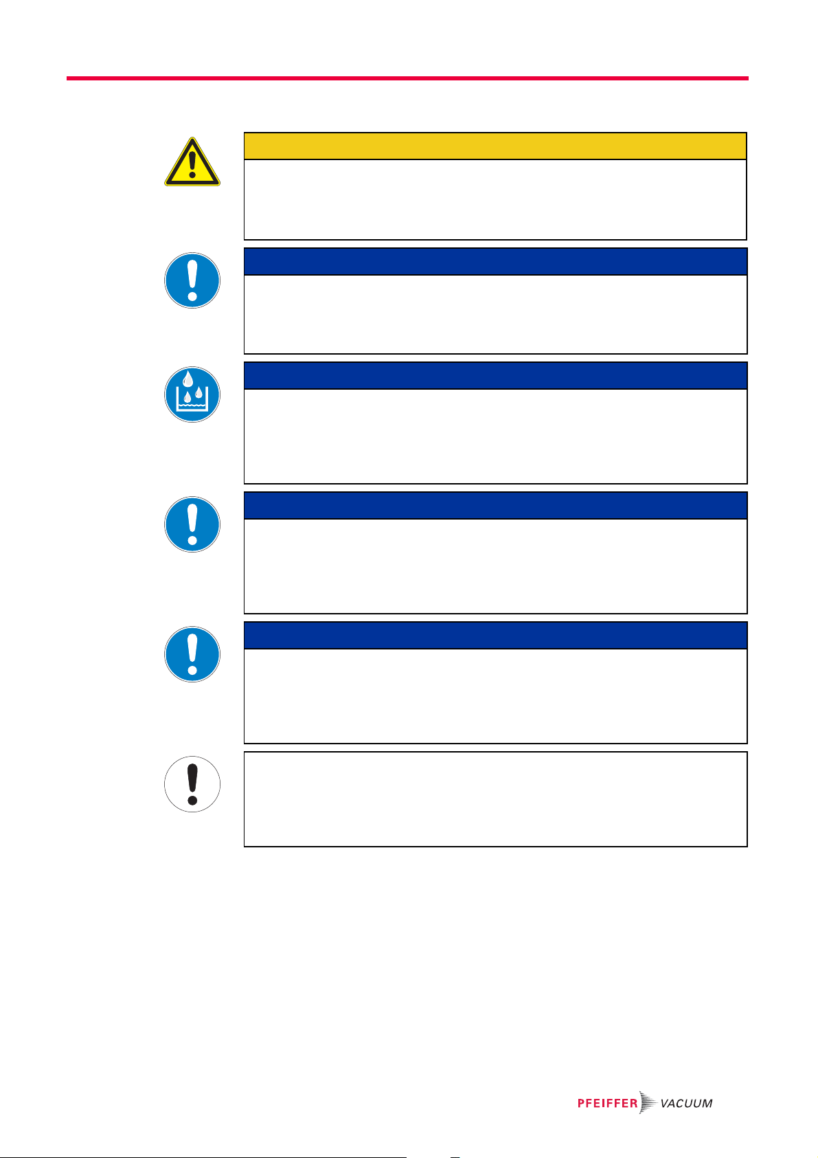
Watch out for excess pressure in the exhaust line.
There is a risk of damage to the seals, and a risk of rupture or overloading of the pump.
Ensure that there is no excess pressure at the OME exit point.
Open the inlet valves either before or at same time as starting the pump.
Pay attention to the back pressure in the C version!
There is a greater back pressure in the C version than with the standard version.
The saturation indicator only displays the correct saturation level of the filter elements
Damage to the pump due to condensate in the operating fluid!
Returned condensate generated by vapors or by temperature differences between the
oil mist eliminator and pump impairs the quality of the operating fluid and negatively impacts the pump's final vacuum.
Drain operating fluid built up with condensate in a time manner.
Operation
CAUTION
NOTICE
at intake pressures < 600 hPa.
NOTICE
NOTICE
Risk of the filter elements becoming blocked with resin!
When pumping gases and vapors with a tendency towards polymerization, the OME filter elements can become resinified.
Observe the corresponding safety devices such as the saturation indicator or pres-
sure relief valve.
NOTICE
Make sure that the return for the operating fluid works.
Operating fluid is only sucked in and returned from an operating pressure of < 800 hPa
and starting from a minimum quantity of operating fluid in the OME.
Long evacuation phases with a high intake pressure should always be followed by
operating phases with a lower operating pressure.
The very smallest of oil particles can only be filtered to a limited degree!
The level of filtering by the filter elements depends on the gas throughput and the particle distribution in the gas flow.
Use the visual saturation indicator as an guide to the degree of saturation of the filter
elements.
13
Maintenance
7 Maintenance
Disclaimer of liability
Pfeiffer Vacuum accepts no liability for personal injury or material damage, losses or operating malfunctions due to improperly performed maintenance. The liability and warranty entitlement expires.
7.1 Draining the operating fluid
If the accumulated operating fluid in the OME is above the top edge of the sight glass 13,
the operating fluid must be drained.
The intervals, at which the operating fluid is drained, depend on the operating conditions.
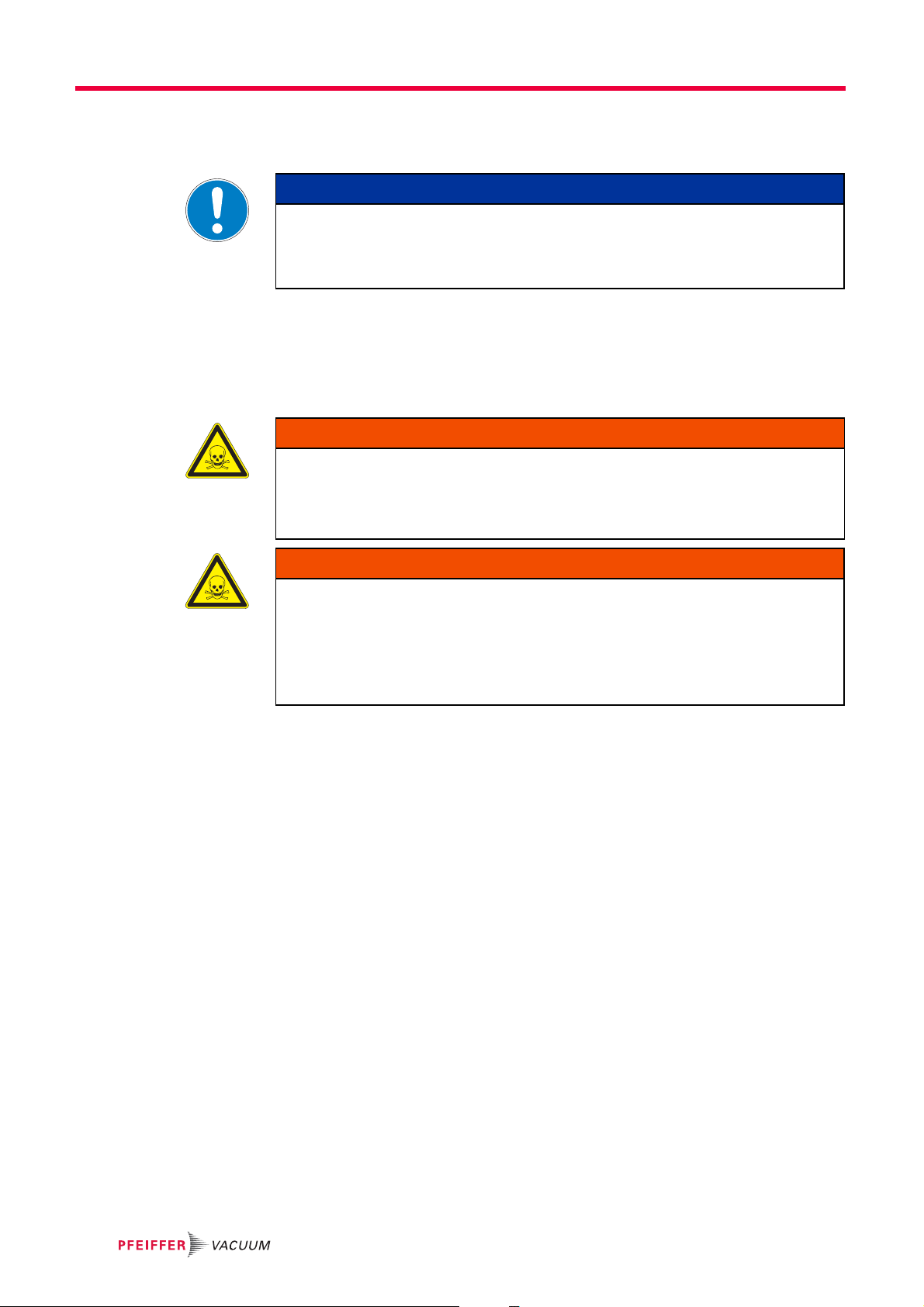
Operating fluid may contain toxic substances from the pumped media!
Danger of poisoning from the emission of harmful substances from the operating fluid.
Wear suitable protective clothing and respirators.
Dispose of operating fluid according to the local regulations
NOTICE
WARNING
WARNING
Toxic vapours!
Danger of poisoning when igniting and heating synthetic operating fluids (e.g. F4/F5)
above 300 °C.
Observe the application instructions.
Do not allow operating fluid to make contact with tobacco products; observe safety
precautions when handling chemicals.
Check the operating fluid level in the sight glass.
Turn off the vacuum pump, vent to atmospheric pressure and allow to cool.
Ensure that the exhaust line is depressurized.
Screw out the operating fluid drain screw 55; pay attention to the O-ring 64.
Drain off operating fluid.
Separate the operating fluid from the condensate.
– If the drained operating fluid is free of contamination, it can be reused.
Screw in operating fluid drain screw 55; pay attention to O-ring.
Dispose of condensate according to the respectively valid legal requirements.
14

Maintenance
Operating fluid return
line
Due to the automatic operating fluid return, it is not necessary to drain the operating fluid
manually.
However, depending on the process, filtered condensate in the oil sump should occasionally be drained in the OME, since it could enter the operating fluid return to the pump.
NOTICE
Make sure that the return for the operating fluid is working properly.
The operating fluid can only be sucked out and returned when there is a minimum about
of operating fluid in the oil mist eliminator.
If necessary, top up with operating fluid in order to ensure the return of operating fluid
at the start of the evacuation phase.
Pour the operating fluid slowly into the outlet flange of the oil mist eliminator until it
can be seen in the sight-glass.
15

Maintenance
7.2 Changing the filter element
The filter element must be exchanged when the exhaust pressure increases, so that
● the pointer enters the red area of the visual saturation indicator 15 or
● the pressure relief valve inside the OME opens and oil mist exits
Contamination of parts and operating fluid by pumped media is possible.
Poisoning hazard through contact with materials that damage health.
In the case of contamination, carry out appropriate safety precautions in order to pre-
vent danger to health through dangerous substances.
Decontaminate affected parts before carrying out maintenance work.
Danger to health by hazardous substances during maintenance or installation
Depending on the process vacuum pumps, components or operating fluids can be contaminated by toxic, reactive or radioactive substances.
Wear adequate protective equipment during maintenance and repairs or in case of
reinstallation.
WARNING
DANGER
Dismantling
Safely dispose of the materials according to the locally applicable regulations.
45
9
8
7
47
12
14
12
6
65
11
2
3
1
52
51
16
Fig. 6: Changing the filter elements
1Casing
2 Cover
3 Flat seal
6Filter cover
7 Valve casing
8 Compression spring
9 Valve buffer
11 Pressure piece
12 Seal
14 Filter element
Carry out preliminary work as described before.
45 Screws
47 Screws
51 Nut
52 Washer
65 O-ring
Maintenance
Remove the operating fluid return line 27, if installed.
Unscrew screws 45 and remove cover 2 with the filter elements from casing 100, col-
lect remaining operating fluid and clean the parts if necessary;
– pay attention to flat seal 3.
Unfasten nuts 51, remove washer 52, pressure piece 11, O-ring 65 and filter cover 6
being careful with seal 12.
Replace filter elements 14; cleaning is not recommended in most cases.
Dismantling the pressure relief valve
Remove screw 47, dismantle valve casing 7 with the valve buffer 9 and compression
spring 8.
Clean all parts and inspect for wear.
Check the sealed surface of valve buffer 9; replace if necessary.
– When assembling lightly oil valve buffer and ensure the correct seating in the valve
casing 7.
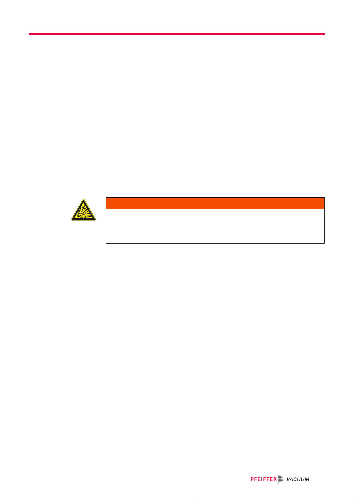
Cleaning Only the filter elements in the C version can be cleaned; the elements in the standard
version must be replaced. The success of the cleaning process depends on the process
medium being used, and should be tested by the user for the specific situation.
WARNING
Explosion hazard
The use of volatile or combustible cleaning agents in vacuum systems can lead to explosive vapour-air mixtures.
After cleaning ventilate and let dry completely.
Clean the filter insert in a solvent bath.
Use blasts of compressed air to expel the cleaning agent from the filter element, and
then dry them.
Assembling Assembling is carried out in reverse order.
Tighten the filter elements at a torque of 3 ... 5 Nm.
– Ensure the correct seating of the seal 12.
Check the pump's ultimate pressure to ensure a leakproof assembly of the operating
fluid return line;
– compare the measurement result with the previously determined ultimate pressure.
Fill in additional operating fluid in OME in order to ensure the return of operating fluid.
17
Maintenance
X
Detail X
35
35.1
38
37
3
100
4
63
142
14
2
2
27
27
25
45
35
36
48
25
28
63
63
67
67
25
28
63
28
67
3
7.3 Cleaning the operating fluid return line
Maintenance intervals depend on the respective process and are recommended as follows.
Check oil for condensate and clean the housing;
– each time the filter of the OME is changed.
Clean and replace possibly the sealing nipple.
– when there is a functional decline in the operating fluid return unit caused by wear
of the sealing nipple.
18
Fig. 7: Cleaning the operating fluid return line
2 Cover
3 Flat seal
4 Connection operating fluid return line
14 Filter element
25 Reducing piece
27 Operating fluid return line
Carry out preliminary work as described before.
Unscrew the screw 48 and remove the clamping plate 36.
Remove floater 35 and cylinder bolt 38.
Check the sealed surface of sealing nipple 37; replace if necessary.
– When assembling lightly oil sealing nipple 37 and ensure the correct seating in the
housing 2.
Clean all parts and inspect for wear.
Assembling is carried out in reverse order.
Check the pump's ultimate pressure to ensure a leakproof assembly of the operating
fluid return line;
– compare the measurement result with the previously determined ultimate pressure.
Fill in additional operating fluid in OME in order to ensure the return of operating fluid.
28 Hollow screw
35 Floater
35.1 Floating support
36 Clamping plate
37 Sealing nipple
38 Cylinder bolt
45 Screws
48 Screw
63 O-ring
67 O-ring
100 Casing
142 Locking screw

8 Service
Service
Pfeiffer Vacuum offers first-class service!
● Fast replacement with exchange products in mint condition
● Advice on the most cost-efficient and quickest solution
Detailed information, addresses and forms at: www.pfeiffer-vacuum.com (Service).
Maintenance and repairs in the Pfeiffer Vacuum ServiceCenter
The following steps are necessary to ensure a fast, smooth servicing process:
Download the forms "Service Request" and "Declaration on Contamination".
Fill out the "Service Request" form and send it by fax or e-mail to your Pfeiffer Vacuum
service address.
Include the confirmation on the service request from Pfeiffer Vacuum with your ship-
ment.
Fill out the declaration on contamination and include it in the shipment (required!).
Drain off operating fluid.
If possible, send pump or unit in the original packaging.
Sending of contaminated pumps or devices
No units will be accepted if they are contaminated with micro-biological, explosive or radioactive substances. “Hazardous substances” are substances and compounds in accordance with the hazardous goods directive (current version). If pumps are contaminated or the declaration on contamination is missing, Pfeiffer Vacuum performs
decontamination at the shipper's expense.
1)
Neutralise the pump by flushing it with nitrogen or dry air.
Close all openings airtight.
Seal the pump or unit in suitable protective film.
Return the pump/unit only in a suitable and sturdy transport container and send it in
Service orders
All service orders are carried out exclusively according to our repair conditions for vacuum units and components.
9 Accessories
Designation OME 40 M
Saturation indicator, optical/electronic for OME 40 M PK 007 308 -T
Oil return unit from OME 40 to Duo 35/65 PK 005 950 -T
while following applicable transport conditions.
1)
Forms under www.pfeiffer-vacuum.com
19

Technical data and dimensions
10 Technical data and dimensions
10.1 Technical data
Parameter OME 40 M/MR OME 40 C/CR
Degree of separation 98 % 98 %
Flange (in) DN 40 flange DN 40 flange
Flange (out) DN 40 ISO-KF DN 40 ISO-KF
Pressure max. (absolute) 1500 hPa 1500 hPa
Exhaust pressure max. Atmosphere Atmosphere
Leak rate < 1 • 10
For Duo 35/65, Duo 35/65 M Duo 35/65 C, Duo 35/65 MC
For pumping speed 35 - 70 m
Capacity 0,7 l 0,7 l
We i g ht 11 k g 11 kg
10.2 Dimensions
-4
Pa m3/s < 1 • 10-4 Pa m3/s
3
/h 35 - 70 m3/h
356
160
350
Fig. 8: OME 40 MR
341
322 46
298
30
142
382
20

11 Spare parts
Please also specify model number of the the rating plate when ordering accessories or
spare parts.
11.1 Spare parts packages
Spare parts package Type No. Model Consisting of
Maintenance kit OME 40 M/MR PK E27 001 -T Standard 3, 12,14, 65
Overhaul kit OME 40 M PK E27 003 -T Standard 3, 9, 12, 13, 14, 60, 62, 63,
Saturation indicator PK 007 307 -T optically 15, 49, 66
Spare parts
OME 40 C/CR PK E27 002 -T C version 3, 12,14, 65
64, 65, 66
OME 40 MR PK E27 004 -T Standard with
return line
OME 40 C PK E27 005 -T C version 3, 9, 12, 13, 14, 60, 62, 63,
OME 40 CR PK E27 006 -T C version with
return line
3, 9, 12, 13, 14, 37, 60, 61,
62, 63, 64, 65, 66, 67
64, 65, 66
3, 9, 12, 13, 14, 37, 60, 61,
62, 63, 64, 65, 66, 67
21

Spare parts
45
9
37
1
3
8
7
12
14
6
11
52
51
12
65
47
54/63
55/64
2
46
57
24
15
60
49
66
1
45
13/62
27
25
63
35
63
67
67
25
28
28
Ansicht/View
A
A
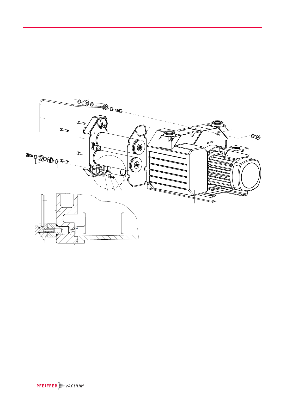
Fig. 9: OME 40 MR
1Casing
2 Cover
3 Flat seal
6Filter cover
7 Valve casing
8 Compression spring
9 Valve buffer
11 Pressure piece
12 Seal
13 Sight glass
14 Filter element
15 Saturation indicator
24 Interchangeable flange
25 Reducing piece
27 Operating fluid return line
28 Hollow screw
35 Float valve
37 Sealing nipple
45 Screws
46 Screw
47 Screws
49 Screw
51 Nut
52 Washer
54 Screw plug
55 Operating fluid drain screw
57 Spring washer
60 O-ring
61 O-ring (previous version, not
shown in the figure)
62 O-ring
63 O-ring
64 O-ring
65 O-ring
66 O-ring
67 O-ring
22

12 Disposal
Disposal
Products or parts thereof (mechanical and electrical components, operating fluids, etc.)
may cause environmental burden.
Safely dispose of the materials according to the locally applicable regulations.
23

VACUUM SOLUTIONS FROM A SINGLE SOURCE
Pfeiffer Vacuum stands for innovative and custom vacuum solutions worldwide,
technological perfection, competent advice and reliable service.
COMPLETE RANGE OF PRODUCTS
From a single component to complex systems:
We are the only supplier of vacuum technology that provides a complete product portfolio.
COMPETENCE IN THEORY AND PRACTICE
Benefit from our know-how and our portfolio of training opportunities!
We support you with your plant layout and provide first-class on-site service worldwide.
Are you looking for a
perfect vacuum solution?
Please contact us:
www.pfeiffer-vacuum.com
Pfeiffer Vacuum GmbH
Headquarters • Germany
T +49 6441 802-0
info@pfeiffer-vacuum.de
 Loading...