

Pfeiffer Vacuum OME 16 M/ATEX, OME 16 ATEX, OME 25 M, OME 25 ML, OME 25 MXL Operating Instructions Manual

OPERATING INSTRUCTIONS
Translation of the original instructions
OME 16 M / ATEX, OME 25 M / ML / MXL
Oil Mist Eliminator
EN
PK 0213 BEN/N (1704)

Table of contents
Table of contents
1 About this manual. . . . . . . . . . . . . . . . . . . . . . . . . . . . . . . . . . . . . . . . . . . . . . . 3
2 Safety . . . . . . . . . . . . . . . . . . . . . . . . . . . . . . . . . . . . . . . . . . . . . . . . . . . . . . . . . 5
3 Transport and storage. . . . . . . . . . . . . . . . . . . . . . . . . . . . . . . . . . . . . . . . . . . . 6
4 Product description. . . . . . . . . . . . . . . . . . . . . . . . . . . . . . . . . . . . . . . . . . . . . . 6
5 Installation . . . . . . . . . . . . . . . . . . . . . . . . . . . . . . . . . . . . . . . . . . . . . . . . . . . . . 8
6 Operation . . . . . . . . . . . . . . . . . . . . . . . . . . . . . . . . . . . . . . . . . . . . . . . . . . . . . 15
7 Maintenance. . . . . . . . . . . . . . . . . . . . . . . . . . . . . . . . . . . . . . . . . . . . . . . . . . . 16
8 Service . . . . . . . . . . . . . . . . . . . . . . . . . . . . . . . . . . . . . . . . . . . . . . . . . . . . . . . 22
9 Accessories . . . . . . . . . . . . . . . . . . . . . . . . . . . . . . . . . . . . . . . . . . . . . . . . . . . 23
10 Technical data . . . . . . . . . . . . . . . . . . . . . . . . . . . . . . . . . . . . . . . . . . . . . . . . . 24
11 Spare parts. . . . . . . . . . . . . . . . . . . . . . . . . . . . . . . . . . . . . . . . . . . . . . . . . . . . 26
12 Disposal . . . . . . . . . . . . . . . . . . . . . . . . . . . . . . . . . . . . . . . . . . . . . . . . . . . . . . 27
1.1 Validity. . . . . . . . . . . . . . . . . . . . . . . . . . . . . . . . . . . . . . . . . . . . . . . . . . . . . 3
1.2 Conventions . . . . . . . . . . . . . . . . . . . . . . . . . . . . . . . . . . . . . . . . . . . . . . . . 3
2.1 Safety precautions . . . . . . . . . . . . . . . . . . . . . . . . . . . . . . . . . . . . . . . . . . . 5
2.2 Proper use . . . . . . . . . . . . . . . . . . . . . . . . . . . . . . . . . . . . . . . . . . . . . . . . . 5
2.3 Improper use. . . . . . . . . . . . . . . . . . . . . . . . . . . . . . . . . . . . . . . . . . . . . . . . 5
3.1 Storage . . . . . . . . . . . . . . . . . . . . . . . . . . . . . . . . . . . . . . . . . . . . . . . . . . . . 6
4.1 Product identification. . . . . . . . . . . . . . . . . . . . . . . . . . . . . . . . . . . . . . . . . . 6
4.2 Function . . . . . . . . . . . . . . . . . . . . . . . . . . . . . . . . . . . . . . . . . . . . . . . . . . . 7
5.1 Assembly . . . . . . . . . . . . . . . . . . . . . . . . . . . . . . . . . . . . . . . . . . . . . . . . . . 8
5.2 Installing the operating fluid return line . . . . . . . . . . . . . . . . . . . . . . . . . . . . 9
7.1 Draining the operating fluid . . . . . . . . . . . . . . . . . . . . . . . . . . . . . . . . . . . . 16
7.2 Changing the filter element . . . . . . . . . . . . . . . . . . . . . . . . . . . . . . . . . . . . 17
7.3 Cleaning the operating fluid return line . . . . . . . . . . . . . . . . . . . . . . . . . . . 19
10.1 Dimensions . . . . . . . . . . . . . . . . . . . . . . . . . . . . . . . . . . . . . . . . . . . . . . . . 25
11.1 Spare parts packages . . . . . . . . . . . . . . . . . . . . . . . . . . . . . . . . . . . . . . . . 26
2

About this manual
1 About this manual
1.1 Validity
This operating manual is for customers of Pfeiffer Vacuum. It describes the functioning
of the designated product and provides the most important information for safe use of
the unit. The description follows applicable EU guidelines. All information provided in this
operating manual refers to the current state of the product's development. The documentation remains valid as long as the customer does not make any changes to the product.
Up-to-date operating instructions can also be downloaded from
www.pfeiffer-vacuum.com.
1.2 Conventions
Safety instructions The safety instructions in Pfeiffer Vacuum operating instructions are the result of risk
evaluations and hazard analyses and are oriented on international certification standards as specified by UL, CSA, ANSI Z-535, SEMI S1, ISO 3864 and DIN 4844. In this
document, the following hazard levels and information are considered:
DANGER
Imminent danger
Indicates an imminent hazardous situation that will result in death or serious injury.
WARNING
Possibly imminent danger
Indicates an imminent hazardous situation that can result in death or serious injury.
CAUTION
Possibly imminent danger
Indicates an imminent hazardous situation that can result in minor or moderate injury.
NOTICE
Command or note
Command to perform an action or information about properties, the disregarding of
which may result in damage to the product.
3

About this manual
Pictographs
Instructions in the
Work instruction: here you have to do something.
Prohibition of an action to avoid any risk of accidents, the disregarding
of which may result in serious accidents
Warning of a displayed source of danger in connection with operation of
the unit or equipment
Command to perform an action or task associated with a source of danger, the disregarding of which may result in serious accidents
Important information about the product or this document
text
Abbreviations OME: Oil mist eliminator
ODK: Oil drain kit (oil return device)
KAS: Condensate separator
Symbols used The following symbols are used consistently throughout in all illustrations:
V
Vacuum flange
Exhaust flange
X
Connection flange OME
4

2Safety
2.1 Safety precautions
Duty to inform
Each person involved in the installation or operation of the unit must read and observe
the safety-related parts of these operating instuctions.
The operator is obligated to make operating personnel aware of dangers originating
from the unit or the entire system.
Before carrying out any work read and observe the operating and safety instructions
of the pumping station and the individual components.
Observe the safety and accident prevention regulations.
Check regularly that all safety precautions are being complied with.
When returning the components to us please note the instructions in the Service sec-
tion.
2.2 Proper use
Only use the oil mist eliminator to filter oil mist from the gas flow of rotary vane pumps.
Simply mount the OME onto the exhaust port of rotary vane pumps.
Use the OME in accordance with the corresponding approved pumping speed.
Safety
2.3 Improper use
Improper use will cause all claims for liability and warranties to be forfeited. Improper use
is defined as usage for purposes deviating from those mentioned above, especially:
pumping of corrosive gases
connection to pumps or units which are not suitable for this purpose according to their
operating instructions
connection to units which have exposed voltage-carrying parts
use of accessories or spare parts, which are not named in this manual
pumping-off of gases and vapors that may be prone to polymerization or may resinify
the filter inserts
5

Transport and storage
3 Transport and storage
3.1 Storage
The OME should be stored dry and protected from moisture. The filter inserts can absorb
moisture, and the lubrication properties of the oil and hence the ultimate pressure can be
negatively influenced in pumps with an oil return unit.
4 Product description
4.1 Product identification
To correctly identify the product when communicating with Pfeiffer Vacuum, always have
the information from the rating plate available.
● Model and model number
● Herstelldatum
Variants
Type Connection nominal diameter intended for pump type
OME 16 M DN 16 ISO-KF Uno 2.5, Uno 5, Uno 6, Duo 1.3, Duo 2.5, Duo 5 M
Duo 1.6, Duo 3, Duo 6, Duo 11
OME 16 ATEX DN 16 ISO-KF Duo 11 ATEX
OME 25 M DN 25 ISO-KF Duo 10 M, Penta 10, Pascal 2005/2010
OME 25 ML DN 25 ISO-KF Duo 20 M, Penta 20, TWIN 20-10
Pascal 2015/2021
OME 25 MXL DN 25 ISO-KF Uno 30 M, Penta 35
6

4.2 Function
2
33
12
30
10
4
X
Product description
The oil mist eliminator is mounted on the exhaust port of rotary vane pumps. It filters oil
mist particles out of the supported stream of gas, thereby reducing the operating fluid
mist discharge.
The filter elements have been installed in a corrosion-resistant aluminium casing and
consist of a glass polyester fleece cylindrical filter. A built-in pressure relief valve opens
if the filter element becomes too dirty so that the maximum operating pressure never
goes above 1500 hPa (absolute). The collected operating fluid can be observed through
a sight-glass and discharged with a drain screw.
To return the filtered operating fluid from the OME into the pump without interrupting the
pump operation, an operating fluid return (optional) can be used.
2 Housing
4 Cover
10 Connection flange
(exhaust flange of rotary vane
pump)
12 Sight glass
30 O-ring
33 Operating fluid drain screw
Operating fluid return
line
Fig. 1: OME 16 M
If the operating fluid accumulated in the OME reaches a specified level, the operating
fluid is channeled via differential pressure back into the rotary vane pump. Condensate
concentrates underneath the oilpan and has to be drained when necessary so as not to
impair the operation of the pump
The use of the operating fluid return increases the operational safety of the pump and
reduces the maintenance requirements.
7

Installation
5 Installation
5.1 Assembly
To install the OME in a vacuum system, ISO small flanges or ISO clamp flanges are provided on the input side and output side. The flanges are provided with protective caps
when delivered to protect the sealing surfaces.
If gases are pumped that may not enter the atmosphere, an exhaust line must be connected to the exhaust flange.
If large amounts of vapor arise during operation, it is recommendable to install a condensate separator between the rotary vane pump and OME so that condensate is removed
in the KAS, and only oil mist enters the OME.
The OME can also be mounted beside the pump. When doing this, the position of the
installation must be maintained and the connecting and return drainage pipes going
down towards the pump be moved.
WARNING
Poisonous substances exit from the exhaust!
There is a poisoning hazard from discharged gases or vapors that can be hazardous
and/or polluting during use.
Install and run the exhaust line so that overpressure cannot build up inside it.
Follow the vacuum pump installation instructions in the respective operating instruc-
tions.
NOTICE
Vacuum component
Dirt and damage impair the function of the vacuum component.
When handling vacuum components, ensure that they are kept clean and are protect-
ed against damage.
Ensure that the connection flange is clean, dry and free of grease.
Turn off the vacuum pump, vent to atmospheric pressure and allow to cool.
Remove the protective caps from the connection flanges.
Place the OME on the exhaust side of the rotary vane pump with the sight glass facing
downward onto the flange, and fasten it with the clamping ring (accessory) or bracket
screws (accessory), if clamp flanges are used; observe centering ring (accessory).
If a centring-ring with an outlet nozzle has been fitted at the side of the pump, re-
place this with a standard version centring-ring.
If an exhaust valve has been fitted in at the side of the pump, this must be removed.
Lay exhaust line from the OME sloping downward so that no condensate can flow
back.
– If an air trap is created in the system, then a device for draining condensation water
must be provided at the lowest point.
OME 16 ATEX If an ATEX version has been installed a stainless-steel clamping ring must definitely
be used. This clamping ring comes included with the pump and ensures that the OME is
properly grounded.
8

5.2 Installing the operating fluid return line
OME
222
223
221/145
33
29
28
V
Make sure that the return for the operating fluid is working properly.
The operating fluid can only be sucked out and returned when there is a minimum about
of operating fluid in the oil mist eliminator.
If necessary, top up with operating fluid in order to ensure the return of operating fluid
at the start of the evacuation phase.
Pour the operating fluid slowly into the outlet flange of the oil mist eliminator until it
can be seen in the sight-glass.
Unscrew operating fluid drain screw 33.
Drain off operating fluid.
Separate the operating fluid from the condensate.
– If the drained operating fluid is free of contamination, it can be reused.
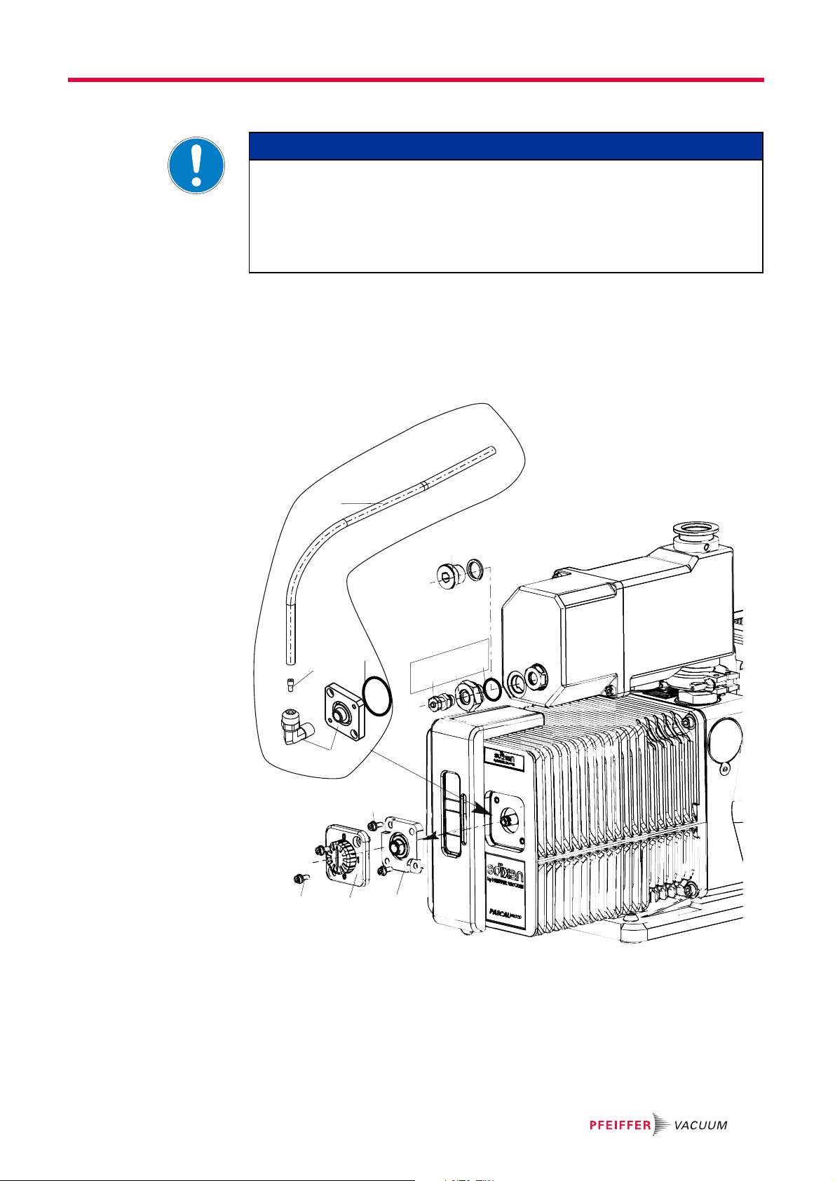
UnoLine, DuoLine
OME 16 M
Installation
NOTICE
Fig. 2: Duo 3 with OME 16 M and ODK
33 Drain screw for operating fluid
28 Screw fitting
29 Closure cap
145 O-ring
221 Hose
222 Operating fluid return
hose
223 Hose clamp
Screw in hose connection 221 in place of the operating fluid drain screw 33; take care
with O-ring 145.
Unscrew and remove the union nut of the screw fitting 28 and remove the sealing plug
29.
Fit operating fluid return hose 222 at both sides,
– keep the hose as short as possible and protect it from bending.
Tighten the union nut of the screw fitting 240.
Fasten hose clip 223.
9

Installation
OME
222
42
223
223
45/148
220/138
221/145
33
OME 16 M
OME 25 M
OME 25 ML
Fig. 3: Duo 10 M withOMEand ODK
33 Operating fluid drain screw
42 Gas ballast valve
45 Intermediate flange
138 O-ring
145 O-ring
148 O-ring
220 Hose nipple
221 Hose piece
222 Operating fluid return line
223 Hose clip
Screw in hose connection 221 in place of the operating fluid drain screw 33; take care
with O-ring 145.
Remove gas ballast valve 42 from the pump and absorb the operating fluid under-
neath.
Re-fit the gas ballast valve 42 with intermediate flange 45 and screw tight with longer
screws (torque: 2.5 Nm); take care with O-ring 148.
Screw fitting/hose nipple 220 into intermediate flange 45 and tighten slightly; pay at-
tention to O-ring 138.
Fit operating fluid return hose 222 at both sides,
– keep the hose as short as possible and protect it from bending.
Fasten hose clips 223.
10

OME 25 MXL
OME
Installation
221/145
223
33
222
42
240
46/148
Fig. 4: Uno 30 M
33 Operating fluid drain screw
42 Gas ballast valve
46 Intermediate flange
145 O-ring
148 O-ring
240 Elbow union
221 Hose piece
222 Operating fluid return line
223 Hose clip
Screw in hose connection 221 in place of the operating fluid drain screw 33; take care
with O-ring 145.
Remove gas ballast valve 42 from the pump and absorb the operating fluid under-
neath.
Re-fit the gas ballast valve 42 with intermediate flange 46 and screw tight with longer
screws (torque: 2.5 Nm); take care with O-ring 148.
Screw elbow union 240 into intermediate flange 46 and tighten slightly.
Fit operating fluid return hose 222 at both sides,
– keep the hose as short as possible and protect it from bending.
Fasten hose clip 223.
11

Installation
PentaLine
OME 25 MXL
221/145
223
222
(33)
28
(29)
Pascal-Reihe
Fig. 5: PentaLine pump with OME and ODK
28 Screw fitting
29 Sealing plug
33 Operating fluid drain screw
145 O-ring
221 Hose piece
222 Operating fluid return line
223 Hose clip
Screw in hose connection 221 in place of the operating fluid drain screw 33; take care
with O-ring 145.
Unscrew and remove the union nut of the screw fitting 28 and remove the sealing plug
29.
Fit operating fluid return hose 222 at both sides,
– keep the hose as short as possible and protect it from bending.
Fasten hose clip 223.
Tighten the union nut of the screw fitting 240.
OME 25 M
OME 25 ML Instead of the drain screw of the operating fluid 33 mount a PK 005 998 -T adapter at
the OME; pay attention to the145 O-ring.
Partially drain operating fluid from the pump.
At the gas ballast valve unscrew both the 101 screws and the 100 cover including the
adjusting knob and the pressure spring.
Unscrew screw 103 and axially remove connecting plate 102; watch out for any leak-
ing operating fluid.
12
Installation
222
210
33
200
101
100
102
103
40
41
145
301
PK 005 998 -T
OME
ODK 1
Fit ODK 1 with adapter (without magnetic valve)
NOTICE
Watch out for any accidental ventilation of the pump
After the ODK 1 has been fitted the pump is not sealed on the exhaust side. This results
in a vacuum chamber attached to the suction side being ventilated once the pump has
been switched off.
Make sure that on the side of a building a magnetic valve is installed on the suction
side.
Fit connection plate ODK 1 at the gas ballast inlet so the elbow is pointing upwards;
pay attention to O-ring 301.
Insert outlet nozzle 210 in the elbow.
Fit operating fluid return hose 222 at both sides,
– keep the hose as short as possible and protect it from bending.
Tighten the union nuts of both screw fittings.
Fig. 6: Fit ODK 1 with PK 005 998 -T OME 25 M / OME 25 ML adapter
33 Drain screw for operating
fluid
40 Screw fitting
41 Reducer
100 Cover
101 Screws
102 Connection plate
103 Screws
145 O-ring
200 ODK 1 connection plate
210 Outlet nozzle
222 Operating fluid return hose
301 O-ring
13

Installation
222
210
300
800
700
33
101
100
102
103
40
41
145
301
PK 005 998 -T
OME
ODK 2
ODK 2 with Adapter (with solenoid valve)
In order to avoid the pump being automatically ventilated via the operating fluid return
line after having been switched off, the magnetic valve (NC/normally closed) of the ODK
2 must be supplied with power at the same time as the engine.
Fig. 7: Fit an ODK with a PK 005 998-T adapter on OME 25 M / OME 25 ML
33 Drain screw for operating
fluid
40 Screw fitting
41 Reducer
100 Cover
101 Screws
Fit the connection plate with magnetic valve 300 at the gas ballast inlet so the elbow
102 Connection plate
103 Screws
145 O-ring
210 Outlet nozzle
222 Operating fluid return hose
300 Connection plate magnetic
valve
301 O-ring
700 Cable connection
800 Magnetic valve coil
is pointing upwards; pay attention to O-ring 301.
Insert outlet nozzle 210 in the elbow.
Fit operating fluid return hose 222 at both sides,
– keep the hose as short as possible and protect it from bending.
Tighten the union nuts of both screw fittings.
Fit coil 800 at the magnetic valve.
Establish a power supply at the coil, paying attention to the correct polarity and volt-
age.
14

6Operation
Watch out for excess pressure in the exhaust line.
There is a risk of damage to the seals, and a risk of rupture or overloading of the pump.
Ensure that there is no excess pressure at the OME exit point.
Open the inlet valves either before or at same time as starting the pump.
Damage to the pump due to condensate in the operating fluid!
Returned condensate generated by vapors or by temperature differences between the
oil mist eliminator and pump impairs the quality of the operating fluid and negatively impacts the pump's final vacuum.
Drain operating fluid built up with condensate in a time manner.
Risk of the filter elements becoming blocked with resin!
When pumping gases and vapors with a tendency towards polymerization, the OME filter elements can become resinified.
Observe the corresponding safety devices such as the saturation indicator or pres-
Operation
CAUTION
NOTICE
NOTICE
sure relief valve.
NOTICE
Make sure that the return for the operating fluid works.
Operating fluid is only sucked in and returned from an operating pressure of < 100 hPa
and starting from a minimum quantity of operating fluid in the OME.
Long evacuation phases with a high intake pressure should always be followed by
operating phases with a lower operating pressure.
Please note that the smallest oil particles can only be separated to a limited extent.
The degree of separation of the filter elements depends upon the gas flow rate and the
distribution of particles in the gas flow.
An increased leakage of oil mist at the exhaust flange of the OME as well as a func-
tional decline in the operating fluid return serve as an indicator of the saturation level
fo the the filter element.
15

Maintenance
7 Maintenance
7.1 Draining the operating fluid
If the accumulated operating fluid in the OME is above the top edge of the sight glass 12,
the operating fluid must be drained.
The intervals, at which the operating fluid is drained, depend on the operating conditions.
Operating fluid may contain toxic substances from the pumped media!
Danger of poisoning from the emission of harmful substances from the operating fluid.
Wear suitable protective clothing and respirators.
Dispose of operating fluid according to the local regulations
Toxic vapours!
Danger of poisoning when igniting and heating synthetic operating fluids (e.g. F4/F5)
above 300 °C.
Observe the application instructions.
Do not allow operating fluid to make contact with tobacco products; observe safety
precautions when handling chemicals.
WARNING
WARNING
Operating fluid return
line
Check the operating fluid level in the sight glass.
Turn off the vacuum pump, vent to atmospheric pressure and allow to cool.
Ensure that the exhaust line is depressurized.
Unscrew operating fluid drain screw 33.
Drain off operating fluid.
Screw in operating fluid drain screw 33; pay attention to O-ring.
Separate the operating fluid from the condensate.
– If the drained operating fluid is free of contamination, it can be reused.
Dispose of condensate according to the respectively valid legal requirements.
Due to the automatic operating fluid return, it is not necessary to drain the operating fluid
manually.
However, depending on the process, filtered condensate in the oil sump should occasionally be drained in the OME, since it could enter the operating fluid return to the pump.
NOTICE
Make sure that the return for the operating fluid is working properly.
The operating fluid can only be sucked out and returned when there is a minimum about
of operating fluid in the oil mist eliminator.
If necessary, top up with operating fluid in order to ensure the return of operating fluid
at the start of the evacuation phase.
Pour the operating fluid slowly into the outlet flange of the oil mist eliminator until it
can be seen in the sight-glass.
16

7.2 Changing the filter element
The filter insert must be exchanged when the exhaust pressure increases until the pressure relief valve opens inside the OME and oil mist exits.
Disclaimer of liability
Pfeiffer Vacuum accepts no liability for personal injury or material damage, losses or operating malfunctions due to improperly performed maintenance. The liability and warranty entitlement expires.
Danger to health by hazardous substances during maintenance or installation
Depending on the process vacuum pumps, components or operating fluids can be contaminated by toxic, reactive or radioactive substances.
Wear adequate protective equipment during maintenance and repairs or in case of
reinstallation.
Contamination of parts and operating fluid by pumped media is possible.
Poisoning hazard through contact with materials that damage health.
In the case of contamination, carry out appropriate safety precautions in order to pre-
vent danger to health through dangerous substances.
Decontaminate affected parts before carrying out maintenance work.
Maintenance
NOTICE
DANGER
WARNING
Dismantling
Safely dispose of the materials according to the locally applicable regulations.
4
30
11
8
28
33
28
2
22
20
18
16
6
14
8.1
12
Fig. 8: OME 16 M, OME 16 ATEX, OME 25 M, OME 25 ML (with OME 25 MXL 8.1 is a part of 8)
2Casing
4 Cover
6 Casing of pressure relief valve
8 Filter insert
11 Deflector
32
12 Sight glass
14 Valve buffer
16 Pressure spring
18 Washer
20 Circlip
22 Compression spring
28 O-ring
30 O-ring
32 Screw
33 Operating fluid drain screw
17

Maintenance
Carry out preliminary work as described before.
Remove OME from the system and pour out the remaining operating fluid.
Unscrew and remove the screws 32 and carefully detach the casing 2 from the cover
4;
– Caution! The parts are under preload.
Detach casing 2 and filter insert 8 and all other internally located parts from cover 4;
take care with O-rings 28 (not with OME 25 MXL) and 30.
Replace filter element 8; cleaning is not recommended in most cases.
Dismantling the pressure relief valve
The pressure relief valve 8.1 at the OME 25 MXL is integrated in the filter insert 8 and
cannot be dismantled.
Loosen circlip 20 with pliers and dismantle washer 18, spring 16 and valve buffer 14
from valve housing 6.
Clean all parts and inspect for wear.
Check the sealed surface of valve buffer 14; replace if necessary.
– When assembling lightly oil valve buffer and ensure the correct seating in the valve
casing 6.
Assembling Continue assembly by reversing the dismantling sequence, paying particular attention to
compliance with the following steps.
Put up cover 4, opening facing upwards.
Lightly oil O-ring 28 (seal at OME 25 MXL).
When mounting casing 2 ensure the correct seating of the filter insert 8 and of the
pressure relief valve casing 6; in particular take care with regard to the position of
compression spring 22 and O-rings 28 and 30.
Tighten screws 32 uniformly to 3 Nm.
18

7.3 Cleaning the operating fluid return line
24
M= 3 Nm
M= 3 Nm
24
25
26
27
23
23
28
29
28
29
222
12
< Index ''A''
≥ Index ''A''
OME
222
42
223
45/148
220/138
When there is a functional decline in the operating fluid return or when changing the filter
element the connecting pipe must be cleaned:
Dismantle and clean the hose connection 222 between OME and the pump.
Uno/Duo 1.6 ... 11
Maintenance
Duo 5 M, 10 M, 20 M
Fig. 9: Dismantling and cleaning the oil return line
Clean the nozzle bore on the underside of the ODK connection 23.
Fig. 10: Dismantling and cleaning the oil return line
Unscrew the hose nipples 220 from the intermediate flange 45 and clean the nozzle
bore.
Screw fitting/hose nipple 220 into intermediate flange 45 and tighten slightly; pay at-
tention to O-ring 138.
19

Maintenance
77
Uno 30 M
2.5 Nm
42
45
Fig. 11: Dismantling and cleaning the oil return line
Remove gas ballast valve 42 from the pump.
Clean the nozzle bore on the underside of the 45 intermediate flange.
Penta 35
20
Fig. 12: Dismantling and cleaning the oil return line
Undo 77 the screws, paying attention to the seal ring.
Unscrew the nozzle with a 2.5 mm hexagon key as the thread of the stator becomes
free and clean it.
Pay attention to the torques when assembling;
– Use for both the screw connection and the nozzle: 2.5 Nm

Pascal 2005 ... 2021
Maintenance
222
210
200
Fig. 13: Dismantling and cleaning the oil return line
Undo the union nut of the elbow and dismantle the 222 operating fluid return hose.
Remove the nozzle 210 from the elbow and clean it.
21

Service
8 Service
Pfeiffer Vacuum offers first-class service!
● Fast replacement with exchange products in mint condition
● Advice on the most cost-efficient and quickest solution
Detailed information, addresses and forms at: www.pfeiffer-vacuum.com (Service).
Maintenance and repairs in the Pfeiffer Vacuum ServiceCenter
The following steps are necessary to ensure a fast, smooth servicing process:
Download the forms "Service Request" and "Declaration on Contamination".
Fill out the "Service Request" form and send it by fax or e-mail to your Pfeiffer Vacuum
service address.
Include the confirmation on the service request from Pfeiffer Vacuum with your ship-
ment.
Fill out the declaration on contamination and include it in the shipment (required!).
Drain off operating fluid.
If possible, send pump or unit in the original packaging.
Sending of contaminated pumps or devices
No units will be accepted if they are contaminated with micro-biological, explosive or radioactive substances. “Hazardous substances” are substances and compounds in accordance with the hazardous goods directive (current version). If pumps are contaminated or the declaration on contamination is missing, Pfeiffer Vacuum performs
decontamination at the shipper's expense.
1)
Neutralise the pump by flushing it with nitrogen or dry air.
Close all openings airtight.
Seal the pump or unit in suitable protective film.
Return the pump/unit only in a suitable and sturdy transport container and send it in
while following applicable transport conditions.
Service orders
All service orders are carried out exclusively according to our repair conditions for vacuum units and components.
22
1)
Forms under www.pfeiffer-vacuum.com

9 Accessories
Designation OME 16 M
Oil return unit ODK from OME 16 M to Duo 1.6, 3, 6, 11, Uno 6 PK 006 080 -T
Oil return unit ODK from OME 16 M to Duo 5 M, from OME 25 M to Duo 10 M, Duo 20 M PK 196 172 -T
Centering ring, FPM/aluminum, DN 16 ISO-KF PF 110 116 -T
Clamping ring, for elastomer seal, DN 10-16 ISO-KF PF 100 316 -T
Designation OME 16 ATEX
Oil return unit ODK from OME 16 ATEX to Duo 11 ATEX PK 006 081 -T
Centering Ring, Stainless Steel 304/1.4301, DN 16 ISO-KF 122ZRG016
Clamping Ring for Elastomer Seal, Stainless Steel 304/1.4301, DN 10-16 ISO-KF 120BSR016
Designation OME 25 M
Oil return unit ODK from OME 25 M, 25 ML, 25 MXL to PentaLine PK 198 545 -T
Oil return unit ODK from OME 16 M to Duo 5 M, from OME 25 M to Duo 10 M, Duo
20 M
Oil drain kit ODK 1 from oil mist eliminator 104360
Oil return unit ODK 2 from OME 25 M/OME 25 ML, magnetic valve 230 V 50/60 Hz,
Pascal 2005–2021
Oil return unit ODK 2 from OME 25 M/OME 25 ML, Pascal 2005–2021, magnetic
valve 115 V, 60 Hz
Oil return unit ODK 2 from OME 25 M/OME 25 ML, Pascal 2005–2021, magnetic
valve 100 V, 50/60 Hz
Oil return unit ODK 2 from OME 25 M/OME 25 ML,Pascal 2005–2021, magnetic
valve 200 V, 50/60 Hz
Oil return unit ODK 2 from OME 25 M/OME 25 ML, Pascal 2005–2021, magnetic
valve 24 V DC
Adapter for OME 25 M/OME 25 ML with ODK on Pascal rotary vane pumps PK 005 998 -T
Centering ring, FPM/Aluminum, DN 25 ISO-KF PF 110 125 -T
Clamping ring, for elastomer seal, DN 20-25 ISO-KF PF 100 325 -T
Accessories
PK 196 172 -T
104361
104362
104363
104364
104365
Designation OME 25 ML
Oil return unit ODK from OME 25 M, 25 ML, 25 MXL to PentaLine PK 198 545 -T
Oil return unit ODK from OME 16 M to Duo 5 M, from OME 25 M to Duo 10 M, Duo 20 M PK 196 172 -T
Oil drain kit ODK 1 from oil mist eliminator 104360
Oil return unit ODK 2 from OME 25 M/OME 25 ML, magnetic valve 230 V 50/60 Hz,
Pascal 2005–2021
Oil return unit ODK 2 from OME 25 M/OME 25 ML, Pascal 2005–2021, magnetic valve
115 V, 60 Hz
Oil return unit ODK 2 from OME 25 M/OME 25 ML, Pascal 2005–2021, magnetic valve
100 V, 50/60 Hz
Oil return unit ODK 2 from OME 25 M/OME 25 ML,Pascal 2005–2021, magnetic valve
200 V, 50/60 Hz
Oil return unit ODK 2 from OME 25 M/OME 25 ML, Pascal 2005–2021, magnetic valve
24 V DC
Adapter for OME 25 M/OME 25 ML with ODK on Pascal rotary vane pumps PK 005 998 -T
Centering ring, FPM/Aluminum, DN 25 ISO-KF PF 110 125 -T
Clamping ring, for elastomer seal, DN 20-25 ISO-KF PF 100 325 -T
104361
104362
104363
104364
104365
Designation ONF 25 MXL
Oil return unit ODK from OME 25 M, 25 ML, 25 MXL to PentaLine PK 198 545 -T
Oil return unit ODK from OME 25 MXL to Uno 30 M PK 196 944 -T
Centering ring, FPM/Aluminum, DN 25 ISO-KF PF 110 125 -T
Clamping ring, for elastomer seal, DN 20-25 ISO-KF PF 100 325 -T
23

Technical data
10 Technical data
Parameter OME 16 M OME 16 ATEX
Degree of separation 99.98 % 99.98 %
Flange (in) DN 16 ISO-KF DN 16 ISO-KF
Flange (out) DN 16 ISO-KF DN 16 ISO-KF
Exhaust pressure, max. Atmospheric pressure Atmospheric pressure
Pressure max. (absolute) 1500 hPa 1500 hPa
For pumping speed 12 m
Capacity 0.15 l 0.15 l
Weight 1.35 kg 1.35 kg
Parameter OME 25 M OME 25 ML ONF 25 MXL
Degree of separation 99.98 % 99.98 % 99.98 %
Flange (in) DN 25 ISO-KF DN 25 ISO-KF DN 25 ISO-KF
Flange (out) DN 25 ISO-KF DN 25 ISO-KF DN 25 ISO-KF
Exhaust pressure, max. Atmospheric pressure Atmospheric pressure Atmospheric pres-
Pressure max. (absolute) 1500 hPa 1500 hPa 1500 hPa
For pumping speed 12 m
Capacity 0.15 l 0.25 l 0.35 l
Weight 1.4 kg 1.6 kg 1.9 kg
3
/h 12 m3/h
sure
3
/h 30 m3/h 42 m3/h
24

10.1 Dimensions
Technical data
DN 2
A
G
C
D
Fig. 14: OME 16 M, OME 16 ATEX, OME 25 M, OME 25 ML
DN 1
G
H
B
DN 25 ISO-KF
E
F
E
105
C
D
A
Fig. 15: OME 25 MXL
Dimensions OME 16 M
OME 16 ATEX
A 142 mm 147 mm 218 mm 284 mm
B 80mm 80mm 80mm 80mm
C 120 mm 132 mm 134 mm 134 mm
D 127 mm 127 mm 182 mm 261 mm
E 16mm 16mm 25mm 25mm
F 105 mm 105 mm 105 mm 105 mm
G 17mm 23mm 27mm 26mm
H48mm48mm
DN1 DN 16 ISO-KF DN 25 ISO-KF DN 25 ISO-KF DN 25 ISO-KF
DN2 DN 16 ISO-KF DN 25 ISO-KF DN 25 ISO-KF DN 25 ISO-KF
OME 25 M OME 25 ML ONF 25 MXL
23
DN 25 ISO-KF
28
B
F3
25

Spare parts
11 Spare parts
The spare parts packages listed here are only applicable for standard models.
Please state all information on the rating plate when ordering spare parts. Other spare
parts than those described in this manual must not be used without the agreement of
Pfeiffer Vacuum.
11.1 Spare parts packages
Spare parts package Model No. Consisting of
Maintenance kit OME 16 M PK E37 001 -T 8, 28, 30
Overhaul kit OME 16 M PK E37 002 -T 8, 12, 14, 16, 18, 20, 22, 28, 30, 33
OME 16 M
OME 16 ATEX
OME 25 M
OME 25 ML
OME 16 ATEX PK E37 001 -T 8, 28, 30
OME 25 M PK E37 001 -T 8, 28, 30
OME 25 L PK E37 003 -T 8, 28, 30
OME 25 XL PK E37 100 -T 8, 30
OME 16 ATEX PK E37 010 -T 8, 12, 14, 16, 18, 20, 22, 28, 30, 33
OME 25 M PK E37 002 -T 8, 12, 14, 16, 18, 20, 22, 28, 30, 33
OME 25 L PK E37 004 -T 8, 12, 14, 16, 18, 20, 22, 28, 30, 33
OME 25 XL PK E37 101 -T 8, 12, 22, 24, 30, 33
4
30
28
2
33
32
12
Fig. 16: OME 16 M, OME 16 ATEX, OME 25 M, OME 25 ML
22
20
18
16
6
14
8.1
11
8
28
26

Disposal
OME 25 MXL
10
4
30
11
8
22
32
2
33
24
12
Fig. 17: OME 25 MXL
12 Disposal
Products or parts thereof (mechanical and electrical components, operating fluids, etc.)
may cause environmental burden.
Safely dispose of the materials according to the locally applicable regulations.
27

VACUUM SOLUTIONS FROM A SINGLE SOURCE
Pfeiffer Vacuum stands for innovative and custom vacuum solutions worldwide,
technological perfection, competent advice and reliable service.
COMPLETE RANGE OF PRODUCTS
From a single component to complex systems:
We are the only supplier of vacuum technology that provides a complete product portfolio.
COMPETENCE IN THEORY AND PRACTICE
Benefit from our know-how and our portfolio of training opportunities!
We support you with your plant layout and provide first-class on-site service worldwide.
Are you looking for a
perfect vacuum solution?
Please contact us:
www.pfeiffer-vacuum.com
Pfeiffer Vacuum GmbH
Headquarters • Germany
T +49 6441 802-0
info@pfeiffer-vacuum.de
 Loading...