

Pfeiffer Vacuum OKTA 1000, OKTA 1000 M, OKTA 4000, OKTA 6000 M, OKTA 4000 M Operating Instructions Manual
...
OPERATING INSTRUCTIONS
EN
OKTA 1000 | OKTA 1000 M
Roots pump
Translation of the Original

Dear Customer,
Thank you for choosing a Pfeiffer Vacuum product. Your new roots pump should support you
in your individual application with full performance and without malfunctions. The name
Pfeiffer Vacuum stands for high-quality vacuum technology, a comprehensive and complete
range of top-quality products and first-class service. From this extensive, practical experience
we have gained a large volume of information that can contribute to efficient deployment and
to your personal safety.
In the knowledge that our product must avoid consuming work output, we trust that our
product can offer you a solution that supports you in the effective and trouble-free
implementation of your individual application.
Please read these operating instructions before putting your product into operation for the
first time. If you have any questions or suggestions, please feel free to contact info@pfeiffer-
vacuum.de.
Further operating instructions from Pfeiffer Vacuum can be found in the Download Center on
our website.
Disclaimer of liability
These operating instructions describe all models and variants of your product. Note that your
product may not be equipped with all features described in this document. Pfeiffer Vacuum
constantly adapts its products to the latest state of the art without prior notice. Please take
into account that online operating instructions can deviate from the printed operating
instructions supplied with your product.
Furthermore, Pfeiffer Vacuum assumes no responsibility or liability for damage resulting from
the use of the product that contradicts its proper use or is explicitly defined as foreseeable
misuse.
Copyright
This document is the intellectual property of Pfeiffer Vacuum and all contents of this
document are protected by copyright. They may not be copied, altered, reproduced or
published without the prior written permission of Pfeiffer Vacuum.
We reserve the right to make changes to the technical data and information in this document.
2/52

Table of contents
1 About this manual 7
1.1 Validity 7
1.2 Target group 7
1.3 Conventions 8
2 Safety 10
2.1 General safety instructions 10
2.2 Safety instructions 10
2.3 Safety precautions 13
2.4 Product usage limits 14
2.5 Proper use 14
2.6 Foreseeable improper use 14
Table of contents
1.1.1 Applicable documents 7
1.1.2 Product variants affected 7
1.3.1 Instructions in the text 8
1.3.2 Pictographs 8
1.3.3 Stickers on the product 8
1.3.4 Abbreviations 9
3 Product description 16
3.1 Functional description 16
3.2 Product identification 16
3.3 Product features 17
3.4 Shipment 17
4 Transportation and Storage 18
4.1 Transporting the vacuum pump 18
4.2 Storing the vacuum pump 19
5 Installation 20
5.1 Installing the vacuum pump 20
5.2 Filling with lubricant 20
5.3 Filling with sealing oil 21
5.4 Connecting the vacuum side 22
5.5 Connecting the fore-vacuum side 23
5.6 Establishing mains connection 23
5.6.1 Connecting a three phase motor with 6-pin terminal board 24
5.6.2 Checking the direction of rotation 25
5.6.3 Connect the PTC thermistor temperature sensor (PTC) 25
6 Operation 27
6.1 Putting the vacuum pump into operation 27
6.2 Switching on the vacuum pump 27
6.3 Adjusting the sealing gas amount 28
6.4 Flushing the suction chamber 28
6.5 Switching off and venting 29
6.6 Re-start (to) 30
7 Maintenance 31
7.1 Maintenance information 31
7.2 Checklist for inspection and maintenance 31
7.3 Changing the lubricant 33
7.4 Changing the sealing oil 34
7.5 Cleaning the suction chamber 35
7.6 Cleaning the overflow valve 36
7.7 Installing the coupling 37
7.8 Installing the coupling for versions with magnetic coupling 38
3/52

Table of contents
8 Decommissioning 39
8.1 Shutting down for longer periods 39
8.2 Recommissioning 39
8.3 Disposing of the vacuum pump 39
9 Malfunctions 41
10 Service solutions from Pfeiffer Vacuum 43
11 Spare parts 45
11.1 Set of seals for version with RSSR 45
11.2 Set of seals for version with magnetic coupling 45
11.3 Maintenance kit for version with RSSR 45
11.4 Maintenance kit for version with magnetic coupling 45
12 Accessories 46
12.1 Sealing gas device 46
12.2 Flushing device 46
12.3 Gear space extraction 46
12.4 Protective strainer 46
13 Technical data and dimensions 47
13.1 General 47
13.2 Technical data 47
13.3 Dimensions 48
Declaration of conformity 50
4/52

List of tables
Tbl. 1: Stickers on the product 9
Tbl. 2: Abbreviations used 9
Tbl. 3: Usage limits of the vacuum pump 14
Tbl. 4: Features of the roots pumps 17
Tbl. 5: Max. permissible flushing quantity 29
Tbl. 6: Maintenance intervals 33
Tbl. 7: Troubleshooting 42
Tbl. 8: Available spare parts packages 45
Tbl. 9: Conversion table: Pressure units 47
Tbl. 10: Conversion table: Units for gas throughput 47
Tbl. 11: Technical data Okta 1000 Standard | M 48
Tbl. 12: Dimensions Okta 1000 Standard | M 49
List of tables
5/52

List of figures
List of figures
Fig. 1: Position of the labels on the product 9
Fig. 2: Design, construction 16
Fig. 3: Transporting the vacuum pump 19
Fig. 4: Filling with lubricant 21
Fig. 5: Filling sealing oil for radial shaft seal rings 22
Fig. 6: Delta connection for low voltage 24
Fig. 7: Star circuit for high voltage 24
Fig. 8: Check of direction of rotation 25
Fig. 9: Connection example with PTC thermistor tripping unit 26
Fig. 10: Drain the lubricant 34
Fig. 11: Replacing the sealing oil for radial shaft seal rings 35
Fig. 12: Overflow valve 36
Fig. 13: Installation instructions gear rim coupling 37
Fig. 14: Dimension diagram Okta 1000 Standard | M 48
6/52
1 About this manual
IMPORTANT
Read carefully before use.
Keep the manual for future consultation.
1.1 Validity
These operating instructions are for customers of Pfeiffer Vacuum. They describe the function of the
designated product and provide the most important information for safe usage of the product. The descriptions comply with applicable directives. All information provided in these operating instructions refer
to the current development status of the product. The documentation remains valid as long as the customer does not modify the product in any way.
1.1.1 Applicable documents
Document Number
Declaration of conformity A component of these instruc-
Additional information for "M Version" PW 0142 BN
Supplementary Information for Roots pumps with special overflow
valves
About this manual
tions
PW 0022 BN
1.1.2 Product variants affected
These instructions apply for roots pumps of the following versions:
Pump type Pump designs
Standard version
M version Changes to the standard design:
Special versions
Standard version:
●
●
●
●
●
●
●
●
●
1.2 Target group
This operating instructions are aimed at all persons performing the following activities on the product:
●
transport,
●
setup (installation),
●
usage and operation,
●
decommissioning,
●
maintenance and cleaning,
●
storage or disposal.
The work described in this document is only permitted to be performed by persons with the appropriate
technical qualifications (expert personnel) or who have received the relevant training from Pfeiffer Vacuum.
Standard motor
The housing and all parts forming the suction chamber consist of GG and GGG
Connection flanges are designed as ISO flanges
Overflow valve for protection against thermal overload
Version with magnetic coupling
Various pressure differentials at the overflow valve
Special seal materials which are resistant to aggressive media
Coated pump interior for corrosion protection and/or good anti-sticking properties
special, process-specific lubricants
7/52

Mod.: Okta 1000
Weight: 240 kg
3
D-35641 Asslar
Made in Germany
Mod.-No.: PP W41 ...
n: max. 4500 1/min Oil: P3 2,9 l
S(N): max. 1775 m /h
02/2019
Ser. -No.:
143..............
Vor Inbetriebnahme Pumpe mit Öl
füllen
Fill the pump with oil before putting
into operation
Remplir la pompe d’huile avant la mise
en route
Achtung!
nur mit D1 befüllen
Attention!
only D1 to be used
Achtung!
nur mit F5 befüllen
Attention!
only F5 to be used
About this manual
1.3 Conventions
1.3.1 Instructions in the text
Usage instructions in the document follow a general structure that is complete in itself. The required action is indicated by an individual step or multi-part action steps.
Individual action step
A horizontal, solid triangle indicates the only step in an action.
►
This is an individual action step.
Sequence of multi-part action steps
The numerical list indicates an action with multiple necessary steps.
1. Step 1
2. Step 2
3. ...
1.3.2 Pictographs
Pictographs used in the document indicate useful information.
Note
Tip
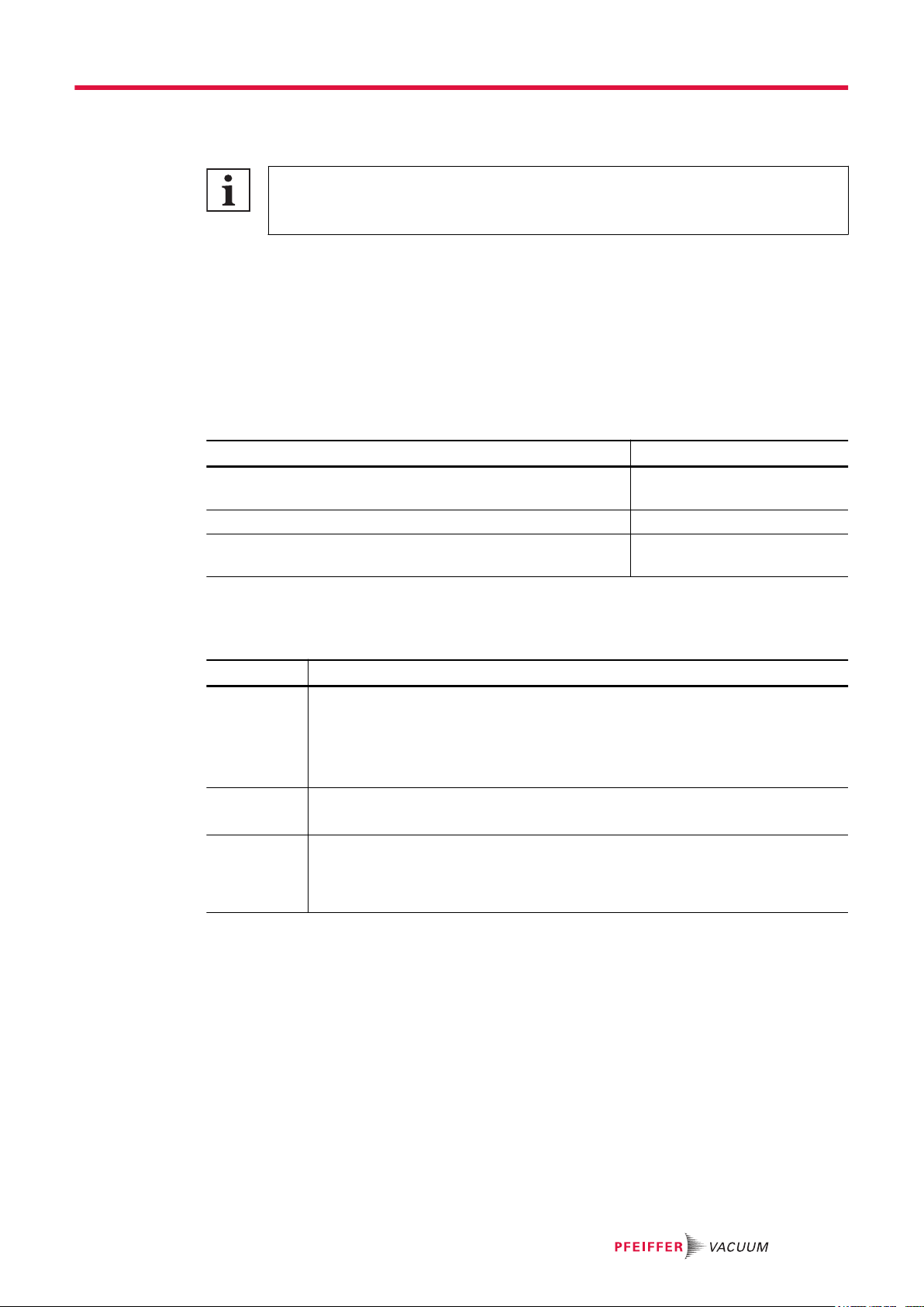
1.3.3 Stickers on the product
This section describes all the stickers on the product along with their meaning.
Rating plate (example)
The rating plate is located on the front side above the sight
glass
Motor rating plate (not shown)
Sticker (red)
Before commissioning, fill the gear and bearing chambers with
lubricant
Sticker (blue) – special lubricant only
Caution: fill with D1 only
8/52
Adhesive label (orange) – only in case of special lubricants
Caution: fill with F5 only
Tbl. 1: Stickers on the product
1
2
3
4
5
6
About this manual
Warning hot surface
This sticker warns of injuries caused by high temperatures in
case of touching without protection during operation.
Warning of magnetic field
This adhesive label warns of injuries to people with pacemakers.
Fig. 1: Position of the labels on the product
1 Rating plate 4 Fill lubricant note
2 Magnetic field warning sign 5 Note D1/F5 lubricant
3 Direction of rotation arrow (cast in the cover) 6 Hot surface warning sign
1.3.4 Abbreviations
Abbreviation Explanation
PTC Temperature-dependent resistor (Positive Temperature Coefficient)
M version Roots pumps with magnetic coupling
RSSR Radial shaft seal ring
WAF width across flats
E Clearance between both coupling halves
GGG Spheroidal graphite cast iron
GG Cast iron with lamellar graphite
FPM Fluoropolymer rubber
PN Nominal pressure stage (pressure nominal)
ISO International Organization for Standardization
DIN German Institute for Standardization (Deutsches Institut für Normung)
f Rotation speed value of a vacuum pump (frequency, in rpm or Hz)
p Intake pressure or general pressure in [hPa]
OI Operating instructions
SI Service instructions
Tbl. 2: Abbreviations used
9/52

Safety
2 Safety
2.1 General safety instructions
This document includes the following four risk levels and one information level.
DANGER
Imminent danger
Indicates a hazardous situation which, if not avoided, will result in death or serious injury.
►
Instructions on avoiding the hazardous situation
WARNING
Possibly imminent danger
Indicates a hazardous situation which, if not avoided, could result in death or serious injury.
►
Instructions on avoiding the hazardous situation
CAUTION
Possibly imminent danger
Indicates a hazardous situation which, if not avoided, could result in minor or moderate injury.
►
Instructions on avoiding the hazardous situation
Danger of property damage
Notice is used to address practices not related to physical injury.
►
Instructions on avoiding property damage
Notes, tips or examples indicate important information on the product or on this document.
2.2 Safety instructions
All safety instructions in this document are based on the results of the risk assessment carried out in
accordance with Machinery Directive 2006/42/EC Annex I and EN ISO 12100 Section 5. Where applicable, all life cycle phases of the product were taken into account.
Risks during transport
WARNING
Risk of serious injury from swinging, toppling or falling objects
During transport, there is a risk of crushing and impact on swinging, toppling or falling objects. There
is a risk of injuries to limbs, up to and including bone fractures and head injuries.
►
Secure the danger zone if necessary.
►
Pay attention to the center of gravity of the load during transport.
►
Ensure even movements and moderate speeds.
►
Observe safe handling of the transport devices.
►
Avoid sloping attachment aids.
►
Never stack products.
►
Wear protective equipment, e.g. safety shoes.
NOTICE
10/52

Safety
Risks during installation
DANGER
Danger to life from electric shock
Contact with exposed and live elements generate an electric shock. Incorrect connection of the mains
supply leads to the risk of live housing parts that can be touched. There is a risk to life.
►
Before the installation, check that the connection leads are voltage-free.
►
Make sure that electrical installations are only carried out by qualified electricians.
►
Provide adequate grounding for the device.
►
After connection work, carry out an earthed conductor check.
WARNING
Risk of crushing from rotating parts
Fingers and hands may be caught by rotating pistons within the connection flange. This results in severe injuries.
►
Keep limbs out of the reach of the roots pump.
CAUTION
Danger of injury from bursting as a result of high pressure in the exhaust line
Faulty or inadequate exhaust pipes lead to dangerous situations, e.g., increased exhaust pressure.
There is a danger of bursting. Injuries caused by flying fragments, the escaping of high pressure, and
damage to the unit cannot be excluded.
►
Route the exhaust line without shut-off units.
►
Observe the permissible pressures and pressure differentials for the product.
►
Check the function of the exhaust line on a regular basis.
CAUTION
Risk of injury from loss of stability
During setup, there is a risk of injury from tipping, if the vacuum pump is not anchored on the standing surface.
►
Secure the vacuum pump using suitable lifting gear.
►
Wear personal protective equipment.
CAUTION
Danger of injury from moving parts
After a power failure or a standstill as a result of overheating, the motor restarts automatically. There
is a risk of injury to fingers and hands if they enter the operating range of rotating parts.
►
Safely disconnect motor from the mains.
►
Secure the motor against reactivation.
►
Dismantle the vacuum pump for inspection, away from the system if necessary.
Risks during operation
WARNING
Danger of poisoning due to toxic process media escaping from the exhaust pipe
During operation with no exhaust line, the vacuum pump allows exhaust gases and vapors to escape
freely into the air. There is a risk of injury and fatality due to poisoning in processes with toxic process
media.
►
Observe the pertinent regulations for handling toxic process media.
►
Safely purge toxic process media via an exhaust line.
►
Use appropriate filter equipment to separate toxic process media.
11/52

Safety
WARNING
Risk of crushing on rotating parts when reaching into the open flange
The pistons continue to run in the vacuum after switching off the motor, and can trap fingers and
hands within their reach.
►
Wait until the vacuum pump comes to a complete standstill.
►
Secure the vacuum pump against re-start.
CAUTION
Danger of burns on hot surfaces
Depending on the operating and ambient conditions, the surface temperature of the vacuum pump
can increase to above 70 °C.
►
Provide suitable touch protection.
CAUTION
Health hazard from increased noise emission
Remaining in the close proximity of the vacuum pump for a sustained period of time may cause hearing damage.
►
Ensure adequate sound insulation.
►
Wear hearing protection.
Risks during maintenance, decommissioning and malfunctions
WARNING
Danger of injury from strong magnetic field
There is a risk of injury for people with pacemakers and medical implants.
►
Make sure that such individuals do not enter the sphere of influence (≤ 2 m) of the magnetic field.
►
Identify rooms in which magnetic couplings are openly accessible with the symbol: "No access
for people with pacemakers".
►
Always keep disassembled couplings away from computers, data carriers, and other electronic
components.
WARNING
Health hazard through poisoning from toxic contaminated components or devices
Toxic process media result in contamination of devices or parts of them. During maintenance work,
there is a risk to health from contact with these poisonous substances. Illegal disposal of toxic substances causes environmental damage.
►
Take suitable safety precautions and prevent health hazards or environmental pollution by toxic
process media.
►
Decontaminate affected parts before carrying out maintenance work.
►
Wear protective equipment.
WARNING
Risk of crushing from rotating parts
Fingers and hands may be caught by rotating pistons within the connection flange. This results in severe injuries.
►
Keep limbs out of the reach of the roots pump.
12/52

Safety
WARNING
Health hazard and environmental damage from toxic contaminated lubricant
Toxic process media can cause lubricant contamination. When changing the lubricant, there is a
health hazard due to contact with poisonous substances. Illegal disposal of toxic substances causes
environmental damage.
►
Wear suitable personal protective equipment when handling these media.
►
Dispose of the lubricant according to locally applicable regulations.
WARNING
Danger of injury due to exposed rotating parts
In the operating range of the motor coupling, there is a danger of clothing being caught and wound
up.
►
When assembling the motor and coupling, make sure that the coupling protection is seated correctly.
►
Wear correct clothing.
CAUTION
Scalding from hot lubricant
Danger of scalding when draining lubricant if it comes into contact with the skin.
►
Wear personal protective equipment.
►
Use a suitable collection receptacle.
2.3 Safety precautions
Duty to provide information on potential dangers
The product holder or user is obliged to make all operating personnel aware of dangers
posed by this product.
Every person who is involved in the installation, operation or maintenance of the product
must read, understand, and adhere to the safety-related parts of this document.
Infringement of conformity due to modifications to the product
The Declaration of Conformity from the manufacturer is no longer valid if the operator
changes the original product or installs additional equipment.
●
Following installation into a system, the operator is required to check and re-evaluate
as necessary the conformity of the overall system in the context of the relevant European Directives before commissioning that system.
General safety precautions
►
Do not expose body parts to the vacuum.
►
Check all safety measures at regular intervals.
►
Observe the safety and accident prevention regulations, if necessary wear personal protective
equipment.
►
Always ensure a secure connection to the earthed conductor (PE), protection class I.
►
Never operate the vacuum pump with open vacuum flange.
►
Provide suitable touch protection, if the surface temperature exceeds 70°C.
►
Provide appropriate noise protection measures in case the sound pressure level requires this.
►
Before working on the vacuum connection, wait until the rotor is at a complete standstill (rotation
speed f = 0).
►
Do not carry out your own conversions or modifications on the vacuum pump.
►
Before returning the vacuum pump, observe the notes in the chapter Service.
13/52

Safety
2.4 Product usage limits
Parameter Okta
Installation location
Installation altitude max. 2,000 m above sea level,
Ambient temperature +5 °C to +40 °C
Relative air humidity max. 85 % (depending on the motor version)
Gas temperature, pressure
side, max.
Intake pressure, max. < 1,100 hPa (abs.)
Orientation Horizontal
●
Indoors, protected against:
─
dust deposits
─
falling objects
─
fire-fighting water
●
Outdoors, protected against:
─
falling objects
─
direct influence of weather such as rain, splash water, strong
drafts and sunlight
─
fire-fighting water
─
lightning strike
at installation altitudes > 1,000m above m.s.l. and an ambient temperature of 40 °C the rated power of the motor reduces by around 10 %
+200 °C
Tbl. 3: Usage limits of the vacuum pump
2.5 Proper use
►
Use the vacuum pump for vacuum generation only.
►
When pumping media with an oxygen concentration level of > 21 %, only use perfluorinated, synthetic oils (F5) as lubricant.
►
Depending on the process and if necessary, use sealing gas.
–
Evacuating high-boiling media (e.g. solvents) degrades the lubricant.
►
Operate the vacuum pump within application limits (see: Product usage limits and Technical data).
►
Adhere to the installation, commissioning, operating, and maintenance instructions.
►
Use only accessory parts recommended by Pfeiffer Vacuum.
2.6 Foreseeable improper use
Improper use of the product invalidates all warranty and liability claims. Improper use is any, even unintended, use, which is contrary to the product purpose; and in particular:
●
Transport, installation or operation of the vacuum pump in an impermissible spatial position
●
Pumping media that can corrode or not be withstood by vacuum pump materials.
Components contained in the suction chamber are cast iron, steel, and stainless steel. Seals are
FKM (alternative seals available on request).
●
Pumping explosive media
●
Pumping radioactive media
●
Pumping media prone to exothermic reactions
●
Pumping media that introduce an ignition source to the suction chamber
●
Pumping media that can cause adhesive deposits to form in the suction chamber, or the pistons to
start up or jam
●
Pumping fluids - flushing media for cleaning are permissible
●
Using the vacuum pump to generate pressure
●
Using the vacuum pump in systems in which sporadic loads and vibrations or periodic forces act
on the unit
●
Use of the vacuum pump in potentially explosive atmospheres
●
Use of the vacuum pump in areas with strong electrical, magnetic or electromagnetic fields
14/52

●
Use of the vacuum pump with open vacuum and/or fore-vacuum flange open to the atmosphere
●
Using lubricants not specified by Pfeiffer Vacuum
●
Using pipes to lift the vacuum pump
●
Use of accessories or spare parts that are not listed in these instructions
●
Using the vacuum pump as a climbing aid.
Safety
15/52
1 42 3
9
8
10111214
1315
5 6
7
Product description
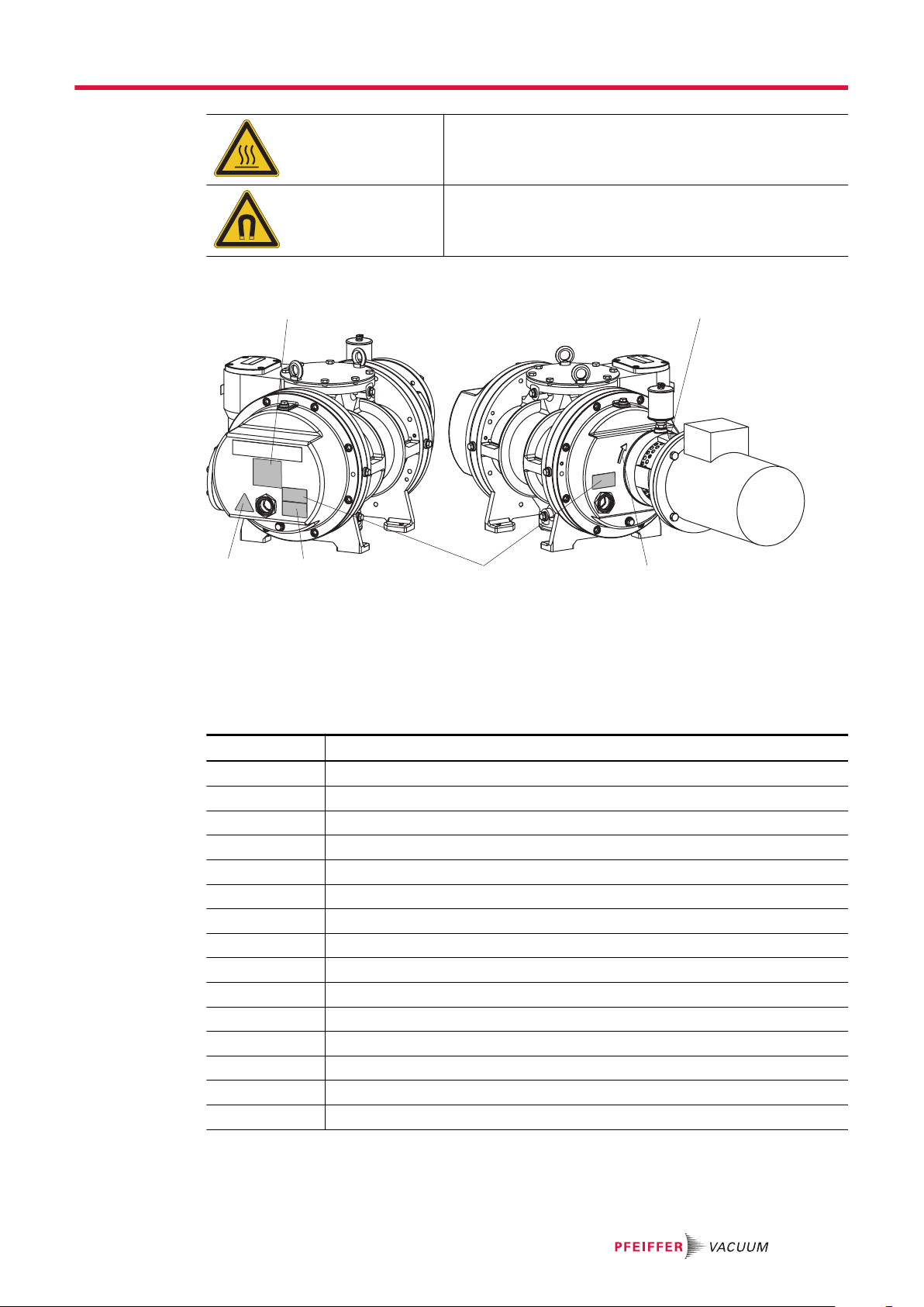
3 Product description
3.1 Functional description
The operating principle of the Roots pumps is based on two synchronous pistons which rotate in a
housing without touching. The pumping effects arise as a result of the opposing rotation of the two figure-of-eight shaped rolling pistons. While suction chambers are formed between the rolling pistons and
the housing, the rolling pistons continuously form a mutual seal without touching each other or the housing. This opposing yet synchronised movement of the rolling pistons is achieved by means of a pair of
gears mounted on the extended shaft ends. Lubrication is limited to the two bearing and gear chambers
which are arranged separately from the suction chambers. As the roots pump is not capable of compressing against atmospheric pressure, it needs to be operated in conjunction with a backing pump connected upstream.
Roots pumps of the M series are equipped with a magnetic coupling.
Fig. 2: Design, construction
1 Vacuum flange 9 Lubricant drain plug
2 Measurement connection vacuum side 10 Fore-vacuum flange
3 Motor 11 Optional fore-vacuum connection
4 Oiler for version with RSSR 12 Sealing gas connection motor side
5 Overflow valve 13 Measurement connection fore-vacuum side
6 Eye bolt 14 Sealing gas connection bearing side
7 Cardboard cover disk 15 Sight glass
8 Lubricant filling plug
3.2 Product identification
To ensure for a clear identification of the product when communicating with Pfeiffer Vacuum, always
keep all of the information on the rating plate to hand.
The following information is shown on the rating plate:
●
Pump model
●
Model number
●
Type and quantity of the lubricant
●
Max. allowable pump rotation speed
●
Date of manufacture
●
Input voltage range
16/52

3.3 Product features
Product description
Tbl. 4: Features of the roots pumps
3.4 Shipment
Flange types Vacuum connec-
tion
Okta 1000 DN 160 ISO-F DN 100 ISO-F 4 × G 3/8" 2 × G 3/8"
Okta 1000 M
Okta 1000
pressure surge protected
Okta 1000 M
pressure surge pro-
tected
●
Roots pump
●
Motor-side coupling half for Roots pumps without motor
●
Seal for the connection flange
●
Cover disks for the connecting flanges
●
Screw kit for the connection flange
●
2 eye bolts for lifting the Roots pump
●
Lubricant P3 (standard version)
●
Operating instructions
DN 150 PN 16 DN 100 PN 16
Fore-vacuum connection
Sealing gas
connection
Measurement
connection
17/52
Transportation and Storage
4 Transportation and Storage
4.1 Transporting the vacuum pump
WARNING
Risk of serious injury from swinging, toppling or falling objects
During transport, there is a risk of crushing and impact on swinging, toppling or falling objects. There
is a risk of injuries to limbs, up to and including bone fractures and head injuries.
►
Secure the danger zone if necessary.
►
Pay attention to the center of gravity of the load during transport.
►
Ensure even movements and moderate speeds.
►
Observe safe handling of the transport devices.
►
Avoid sloping attachment aids.
►
Never stack products.
►
Wear protective equipment, e.g. safety shoes.
Instructions for safe transport
●
Only remove the protective cover for the connection flange once the pipes have been
mounted.
●
Fill the gear and bearing chambers with lubricant only once the final installation position is reached.
Pfeiffer Vacuum recommends keeping the transport packaging and original protective cover.
General information regarding safe transport
1. Observe weight specified on the rating plate.
2. Where possible, always transport or ship the roots pump in its original packaging.
3. Remove the protective cover only immediately prior to installation.
Transporting the vacuum pump in its packaging
1. Use a pallet truck to transport the vacuum pump in its packaging.
2. Note the center of gravity of the load.
3. Observe safe handling of manually operated transport devices.
4. Ensure harmonious movements and moderate speeds.
5. Ensure a flat substrate.
6. Wear protective equipment, e.g. safety shoes.
18/52
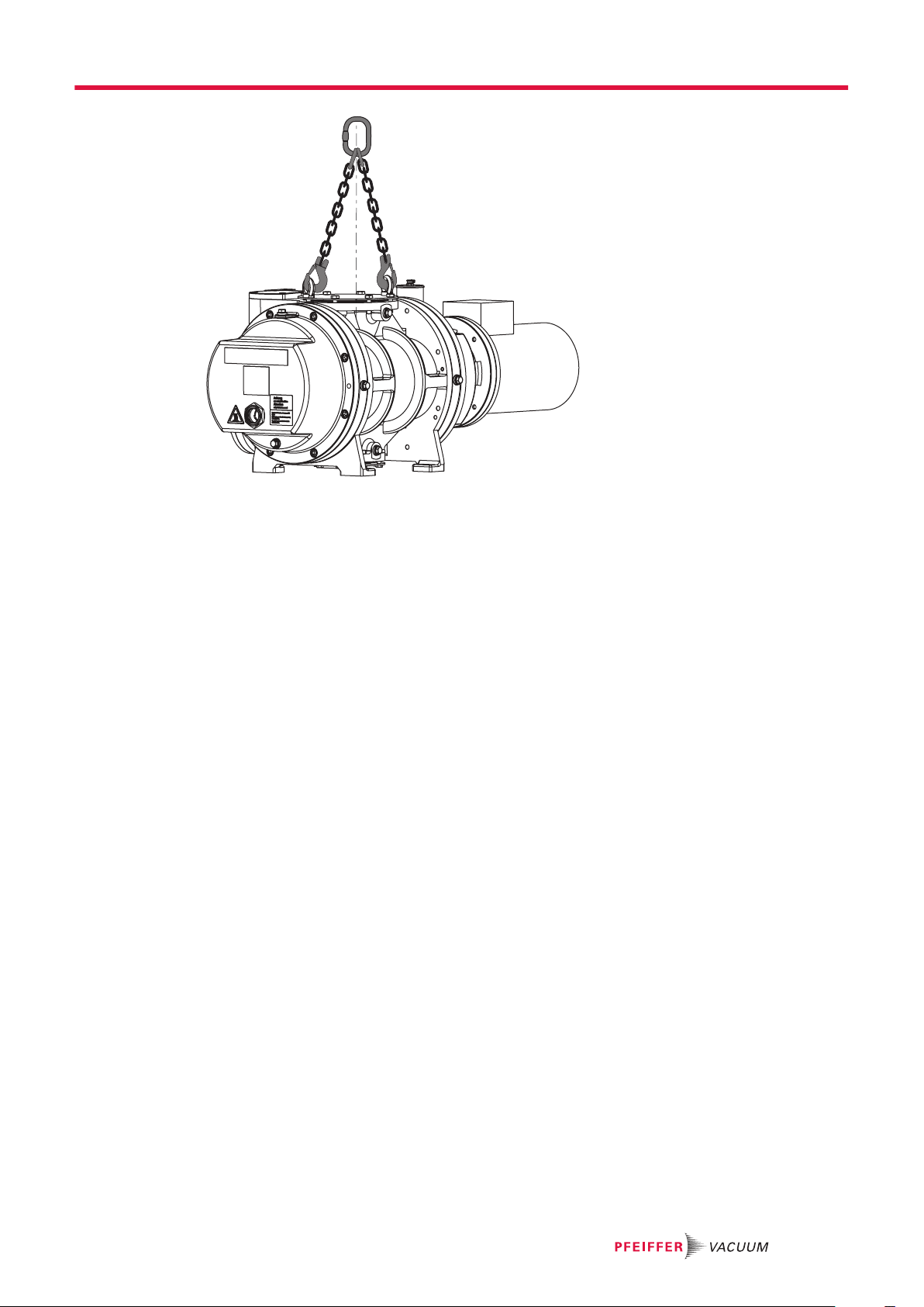
Fig. 3: Transporting the vacuum pump
Transportation and Storage
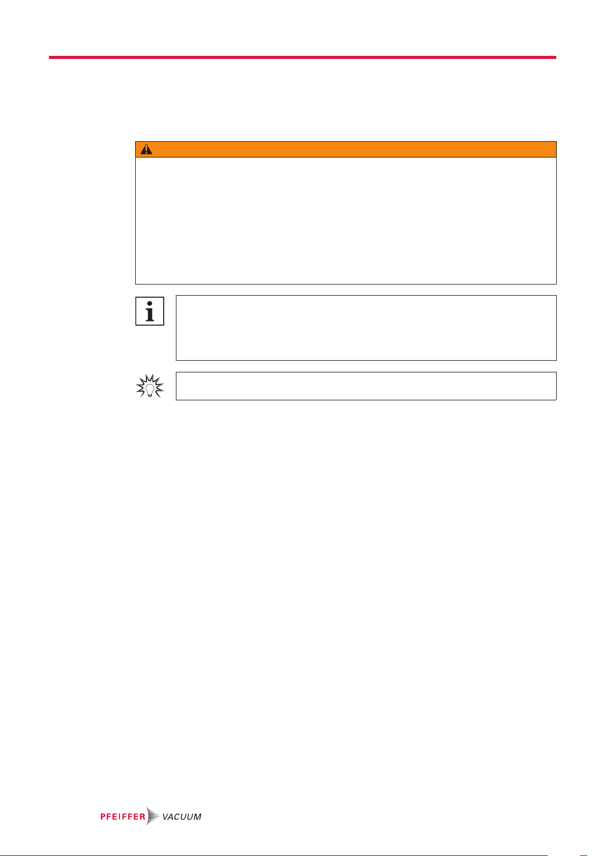
Transporting the vacuum pump without its packaging
2 eye bolts are included in the shipment, which are firmly bolted to the vacuum pump ex-factory.
1. Unpack the vacuum pump.
2. Attach suitable lifting tools to both eye bolts.
3. Pay attention to the correct use and fastening of the lifting equipment.
4. Lift the vacuum pump out of the transport packaging vertically.
5. If necessary, remove the eye bolts after transport and installation.
–
Keep the eye bolts for future use.
4.2 Storing the vacuum pump
The roots pumps do not have any corrosion protection on the inside. If you intend to store the roots
pump for longer periods, we recommend that you use a special corrosion protection agreed with us.
Procedure
1. Close both connection flanges.
2. Check that the other openings are sealed safely, e.g. sealing gas and measurement connections.
3. Store the roots pump only in dry, dust-free rooms, within the specified ambient conditions:
–
In rooms with humid or aggressive atmospheres, seal the roots pump airtight in a plastic bag,
together with a drying agent.
–
After a storage period of 2 years, Pfeiffer Vacuum recommends changing the lubricant.
The best corrosion protection for the roots pump is achieved by evacuating and then filling the suction
chamber with nitrogen.
19/52

Installation
5 Installation
5.1 Installing the vacuum pump
CAUTION
Risk of injury from loss of stability
During setup, there is a risk of injury from tipping, if the vacuum pump is not anchored on the standing surface.
►
Secure the vacuum pump using suitable lifting gear.
►
Wear personal protective equipment.
General notes for the installation of vacuum components
►
Choose an installation location that permits access to the product and to supply lines at all times.
►
Observe the ambient conditions given for the area of use.
►
Provide the highest possible level of cleanliness during assembly.
►
Ensure that flange components during installation are grease-free, dust-free and dry.
Procedure
1. Check the carrying capacity of the floor at the installation location.
2. Place the vacuum pump on a flat, horizontal and fixed surface, to safeguard the lubricant supply.
–
Reference surface is the vacuum flange.
3. Screw the 4 feet of the vacuum pump on level with the standing surface.
4. If necessary, use adjustment elements from the Pfeiffer Vacuum accessories range for mounting
the feet horizontally.
5. When doing so, make sure that the vacuum pump is not tensioned.
6. When installing the pump in a closed housing, ensure adequate air circulation.
7. Keep both sight glasses freely accessible for checks and maintenance.
8. Ensure that the motor rating plate remains accessible at all times for a clear view of the voltage
and frequency specifications.
9. Maintain the minimum distances to bordering surfaces to guarantee sufficient air circulation.
10. Leave the filling/drain holes and sight glasses freely accessible.
11. Fill with lubricant prior to first commissioning.
5.2 Filling with lubricant
WARNING
Danger of poisoning from toxic vapors
Igniting and heating synthetic lubricants generates toxic vapors. Danger of poisoning if inhaled.
►
Observe the application instructions and precautions.
►
Do not allow tobacco products to come into contact with the lubricant.
Property damage from using non-approved lubricant
Attainment of product-specific performance data is not ensured. If non-approved lubricant is used, all
liability and warranty claims against Pfeiffer Vacuum are excluded.
►
Use approved lubricant only.
►
Use other application-specific lubricant only after consultation with Pfeiffer Vacuum.
The type of lubricant specified for the gear and bearing chambers, and the fill quantity for the entire
roots pump are shown on the rating plate. Only the lubricant used during initial installation is permissible. Subsequent change is possible only after consultation with Pfeiffer Vacuum.
NOTICE
20/52
max.
min.
1
2
3
4
6
5
Fig. 4: Filling with lubricant
1 Lubricant filling plug 4 O-ring
2 O-ring 5 Sight glass, motor side
3 Lubricant filling plug 6 Sight glass, gearbox side
Installation
Permissible lubricants
●
P3 for standard version
●
D1 for special applications (such as higher operating temperatures)
●
F5 for corrosive gas model
●
Other lubricants on request
Required tools
●
Open-end wrench, 17 mm WAF
●
Calibrated torque wrench (tightening factor ≤ 2.5)
Procedure
1. Unscrew and remove the lubricant filler screws.
2. Fill the lubricant on both sides while observing the sight glass.
–
Fill levels for the first fill: approx. 5 mm above the sight glass middle.
3. Seal the filler screws.
–
Tightening torque: 32 Nm
4. Check the fill level during operation in the final vacuum.
5. If necessary, top up the lubricant only when the Roots pump is switched off and flooded.
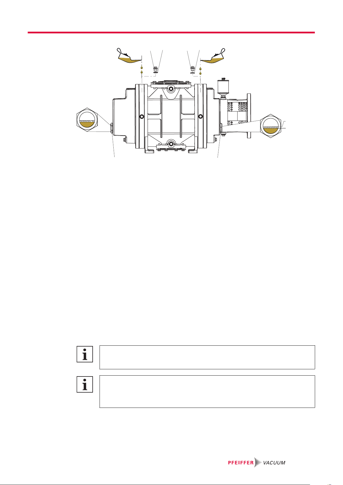
5.3 Filling with sealing oil
Versions with radial shaft seal ring:
This section is only valid for Roots pumps with radial shaft seal ring. The version with magnetic coupling "M" does not have a lubricator.
Overfilling the oiler
The lubricant expands when the roots pump heats up, which could cause lubricant to leak if
overfilled.
Oiler fill level with roots pump in cold state: to max. halfway.
The shaft feedthrough of the drive shaft is sealed with purge oil-covered radial shaft seal rings and fed
by a lubricator on the lantern. The sealing oil type is the same as the lubricant.
21/52
1
Installation
Fig. 5: Filling sealing oil for radial shaft seal rings
1 Oiler
Consumable
●
Sealing oil (lubricant)
Procedure
1. Open the filler flap on the oiler.
2. Fill the oiler with lubricant to max. halfway.
3. Close the filler flap.
4. Always make sure that the lubricator is screwed tightly to the vacuum pump.
5.4 Connecting the vacuum side
WARNING
Risk of crushing from rotating parts
Fingers and hands may be caught by rotating pistons within the connection flange. This results in severe injuries.
►
Keep limbs out of the reach of the roots pump.
Property damage from intake of solid particles
During commissioning, there is a risk of damage to the suction chamber from dirt from the system or
the pipes.
►
Use a suitable protective strainer ("start-up strainer") in the intake flange.
►
Ensure that this strainer is only removed when the risk of solid particles entering the vacuum
pump can be excluded.
–
Observe any pumping speed decrease.
Procedure
1. Degrease the connection flange.
2. Clear welded lines of any tinder, loose parts or similar before installation.
3. Establish the shortest possible connection between the roots pump and vacuum chamber; equiva-
lent to the nominal flange diameter as a minimum.
4. Route the piping between the vacuum pump and vacuum chamber so that it remains as short as
possible; at a minimum, the nominal diameter of the pump flange.
5. Select a larger nominal diameter for pipe lengths > 5 m.
6. Support or suspend the piping to the vacuum pump so that no piping system forces act on the
vacuum pump.
7. Always use all prescribed screws to fasten the flange.
NOTICE
22/52
5.5 Connecting the fore-vacuum side
WARNING
Risk of crushing from rotating parts
Fingers and hands may be caught by rotating pistons within the connection flange. This results in severe injuries.
►
Keep limbs out of the reach of the roots pump.
CAUTION
Danger of injury from bursting as a result of high pressure in the exhaust line
Faulty or inadequate exhaust pipes lead to dangerous situations, e.g., increased exhaust pressure.
There is a danger of bursting. Injuries caused by flying fragments, the escaping of high pressure, and
damage to the unit cannot be excluded.
►
Route the exhaust line without shut-off units.
►
Observe the permissible pressures and pressure differentials for the product.
►
Check the function of the exhaust line on a regular basis.
Procedure
1. Choose a minimum pipe cross section equal to the nominal diameter of the pressure flange.
2. Clear welded lines of any tinder, loose parts or similar before installation.
3. Route the pipes such that no mechanical tension can act on the roots pump or the backing pump.
4. Install a bellows in the piping if necessary.
5. Ensure that mating flanges are in a parallel position.
6. Install the pipes downward from the roots pump, so that condensate does not flow back into the
roots pump.
7. Install a condensate separator if necessary.
8. If an air trap is created in the system, then install a condensate drain facility at the lowest point.
Installation
5.6 Establishing mains connection
DANGER
Danger to life from electric shock
Contact with exposed and live elements generate an electric shock. Incorrect connection of the mains
supply leads to the risk of live housing parts that can be touched. There is a risk to life.
►
Before the installation, check that the connection leads are voltage-free.
►
Make sure that electrical installations are only carried out by qualified electricians.
►
Provide adequate grounding for the device.
►
After connection work, carry out an earthed conductor check.
WARNING
Danger to life from electric shock due to improperly performed installation
The device uses voltage that is dangerous on contact as the electrical power supply. Potentially fatal
situations arise due to unsafe or incorrectly installation when reaching into the device.
►
Ensure that the system is safely integrated into an emergency off safety circuit.
►
Do not carry out any unauthorized modifications or changes to the device.
CAUTION
Danger of injury from moving parts
After a power failure or a standstill as a result of overheating, the motor restarts automatically. There
is a risk of injury to fingers and hands if they enter the operating range of rotating parts.
►
Safely disconnect motor from the mains.
►
Secure the motor against reactivation.
►
Dismantle the vacuum pump for inspection, away from the system if necessary.
23/52
W2
U1
L1
V2
V1
W1
U2
L3
L2
W2
U2
V2
U1
V1
W1
L1
L2
L3
W2
U1
L1
V2
V1
W1
U2
L3
L2
W2
U2
V2
U1
V1
W1
L1
L2
L3
Installation
NOTICE
Risk of damage from excess voltage!
Incorrect or excessive mains voltage will destroy the motor.
►
Always observe the motor rating plate specifications.
►
Route the mains connection in accordance with locally applicable provisions.
►
Always provide a suitable mains fuse to protect the motor and supply cable in the event of a fault.
–
Pfeiffer Vacuum recommends the circuit breaker type "K" with slow tripping characteristic.
NOTICE
Motor damage from overheating
Limited motor fan cooling capacity, caused by low speeds, causes the motor to overheat.
►
During operation with frequency converter, observe the rotation speed range specified in the
technical data.
Depending on the pump type, different motor designs or mains voltages can be used:
●
Three-phase motor with thermistor temperature sensor (PTC), without switch and mains cable
5.6.1 Connecting a three phase motor with 6-pin terminal board
NOTICE
Risk of damage from high starting torque
The specific load behavior of the vacuum pump requires direct on-line starting at full motor power.
Engine damage can occur if a different starting circuit is used.
►
Always start the motor directly.
►
Never use a star-delta start-up circuit.
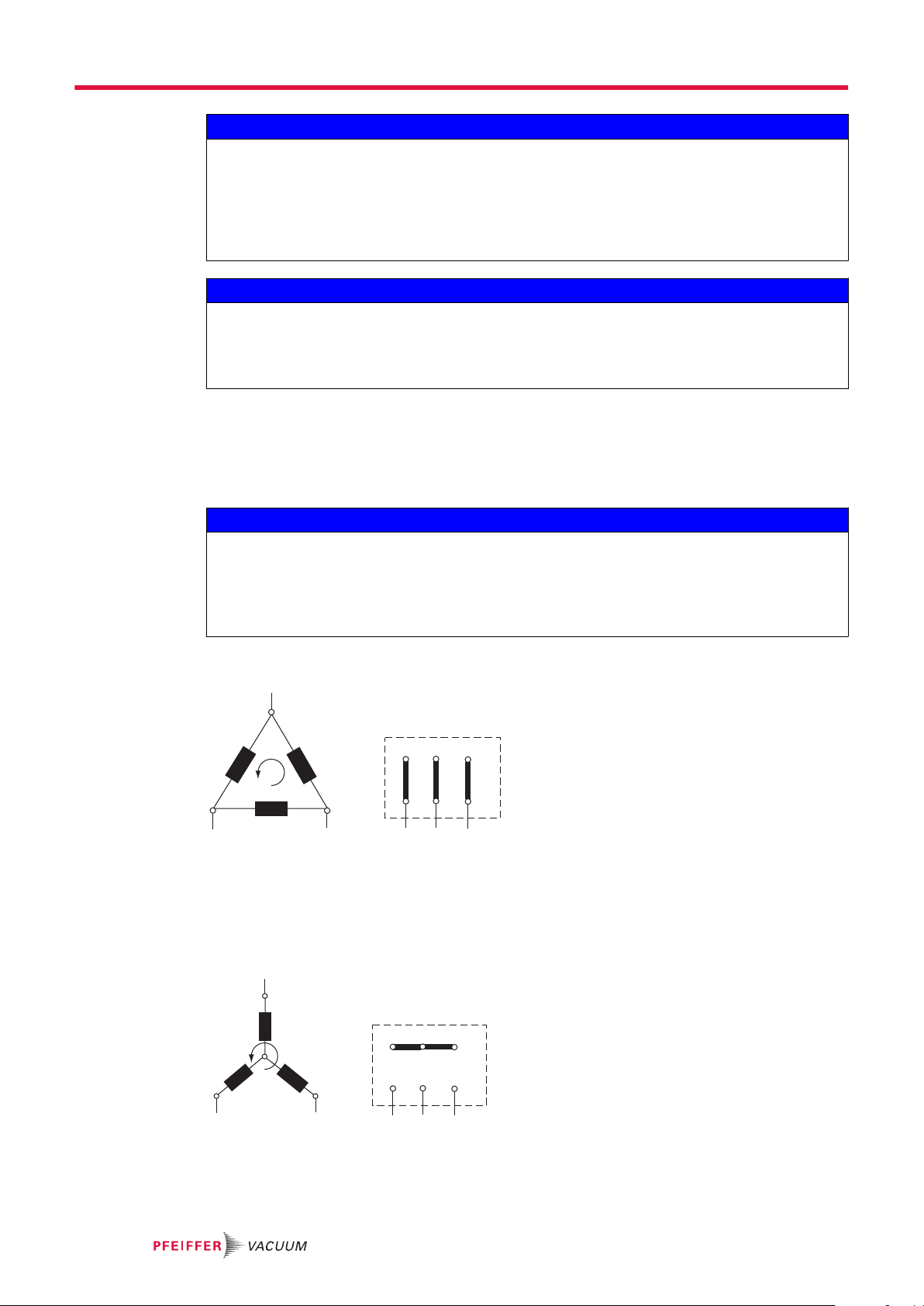
Ports U1 – L2, V1 – L1 and W1 – L3 rotate the motor shaft clockwise when looking at the motor fan.
Fig. 6: Delta connection for low voltage
The 3 phases are connected in series and the connection points connected to the mains. The voltage
per phase is equal to the mains voltage, while the mains current is √3 times the phase current. The delta connection is marked with the Δ symbol. The voltage between the incoming mains supply lines is
called mains voltage. The mains current is the current flowing in the incoming supply lines.
24/52
Fig. 7: Star circuit for high voltage
The ends of the 3 phases are connected in the star point. The terminal voltage is √3 times the phase
voltage, the mains current is equal to the phase current. The star circuit is marked with the Y symbol.
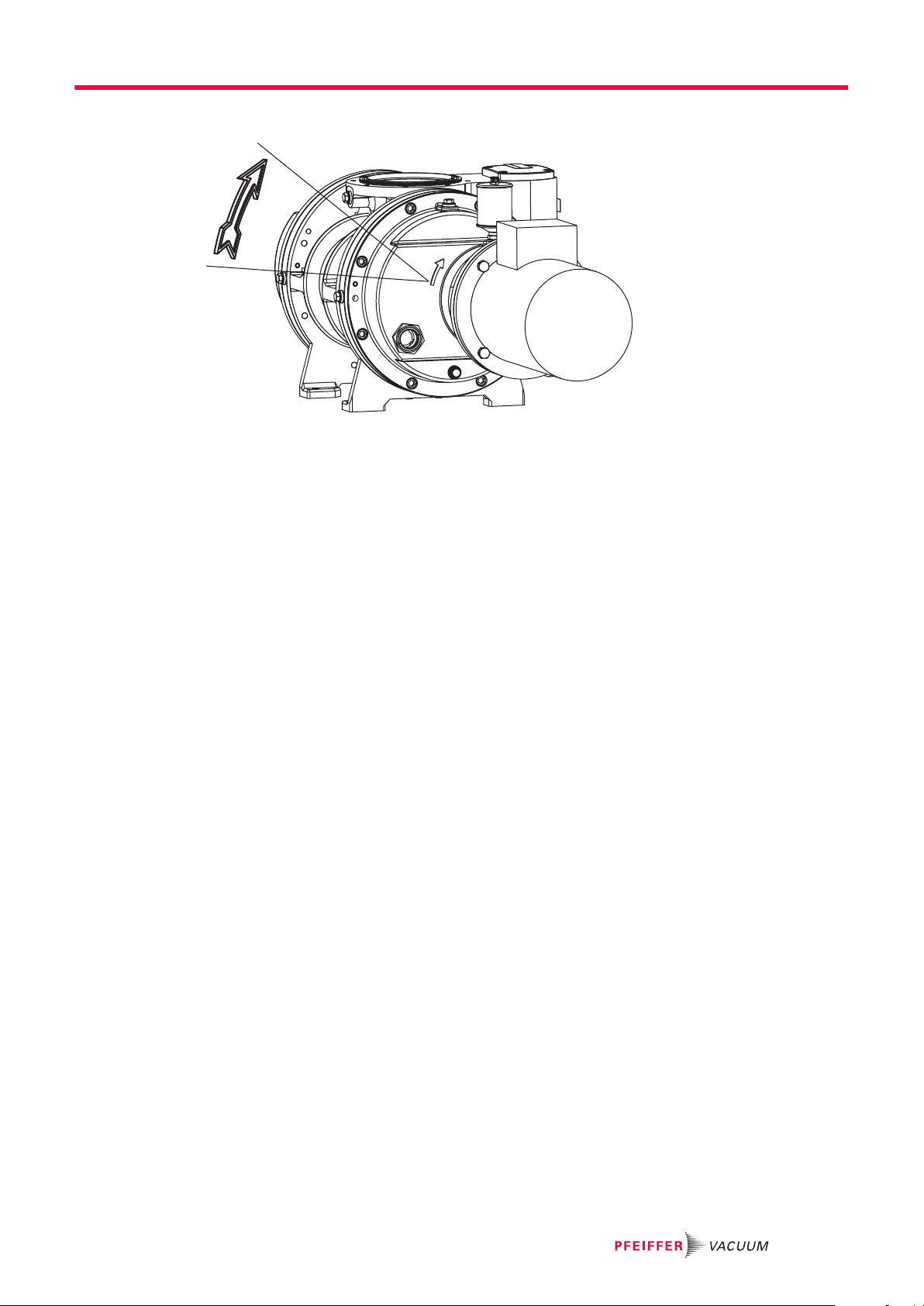
5.6.2 Checking the direction of rotation
Fig. 8: Check of direction of rotation
Procedure
When switching on for the first time, check the roots pump direction of rotation.
1. Switch the vacuum pump on briefly (2 to 3 seconds)
–
The motor and coupling must rotate clockwise (see directional arrow on housing cover).
2. If the direction of rotation is incorrect, swap the 2 phases of the connection cable in the terminal
box.
Installation
5.6.3 Connect the PTC thermistor temperature sensor (PTC)
Connect pump motors equipped with PTC thermistor temperature sensors in the stator winding to a
PTC resistor tripping device for protection against overload.
Other proven motor monitoring systems are also possible.
25/52

N
L1
M
3
L2
L3
F1 - F3
K1
10
11
AC 220 ... 240 V
Us
F4
U
V
W
S1
S2
k1
K1
H1
S3
2)
A1 A2 T1 T2 Y2Y1 24 21 22 14 1211
2)
2)
1)
1)
1)
T1...T3
3)
Installation
Fig. 9: Connection example with PTC thermistor tripping unit
U
S
S
S
K1 Contactor
F1 – F4 Fuses
Control voltage T1 – T3 PTC resistor sensor
S
OFF button H1 Tripping indicator
1
ON button M Motor, 3-phase
2
3
RESET button
1)
2)
3)
For devices with two relay outputs only
For MSR type (model) only
Only for order no.: P 4768 052 FQ
Procedure
►
After shut-down, switch the tripping unit back on manually via the installed RESET button or via
the external RESET S3. Tripping units store the shut-down.
–
Switching on mains detected as automatic RESET.
26/52

6 Operation
6.1 Putting the vacuum pump into operation
Before switching on
1. Check the lubricant levels on both sight glasses.
2. Compare the voltage and frequency specifications on the motor rating plate with the available
mains voltage and frequency.
3. Make sure that the suction chamber is free from all foreign matters.
4. Check the vacuum pump for visible damage and put the vacuum pump into operation only in a
correct state.
5. Protect the vacuum pump from sucking in contamination using suitable measures (e.g. dust filter).
6. Make sure that the shut-off units on the pressure side open before starting the pump.
6.2 Switching on the vacuum pump
WARNING
Danger of poisoning due to toxic process media escaping from the exhaust pipe
During operation with no exhaust line, the vacuum pump allows exhaust gases and vapors to escape
freely into the air. There is a risk of injury and fatality due to poisoning in processes with toxic process
media.
►
Observe the pertinent regulations for handling toxic process media.
►
Safely purge toxic process media via an exhaust line.
►
Use appropriate filter equipment to separate toxic process media.
Operation
CAUTION
Danger of burns on hot surfaces
Depending on the operating and ambient conditions, the surface temperature of the vacuum pump
can increase to above 70 °C.
►
Provide suitable touch protection.
Supplementary Information for Roots pumps with special overflow valves
Upon request, you can obtain supplementary information PW0022 from Pfeiffer Vacuum
Download Center.
Procedure in case of open overflow valve
1. The customer must provide an appropriate start-up circuit (e.g., contactor circuit) for switching on
the Roots pump simultaneously with the backing pump.
2. Allow the vacuum pump to warm up with the vacuum flange closed, for approx. 30 minutes prior to
the process start.
The overflow valve is open at the beginning of evacuation in high pressures ranges. This protects the
Roots pump from overload. As of a differential pressure below 45 mbar between the suction pressure
side, the overflow valve closes.
Procedure in case of a blocked overflow valve
1. Switch on the Roots pump only at a pressure at which the backing pump can handle over the de-
livered gas quantity.
2. If you want to switch on the Roots pump at the same time as the backing pump, you must use a
frequency inverter to limit the torque in the event of overload.
3. Allow the vacuum pump to warm up with the vacuum flange closed, for approx. 30 minutes prior to
the process start.
27/52

Operation
Checking the lubricant level
1. Regularly check the lubricant level while the vacuum pump is running and at operating tempera-
ture.
2. Make sure that the level is in the area at the center of the sight glass.
3. Check the lubricant fill level daily during continuous operation or whenever the vacuum pump is
switched on.
6.3 Adjusting the sealing gas amount
Property damage from impermissibly high sealing gas pressure
Excessive sealing gas pressure leads to damage to the seals after switching on the vacuum pump.
►
Observe the max. permissible sealing gas pressure.
►
Reduce the sealing gas pressure to < 1200 hPa.
►
Stop the sealing gas supply immediately after switching off the vacuum pump.
Equation for calculating the sealing gas flow:
QS = (Sth × p × AS)/p
●
QS = Sealing gas flow under standard conditions [Nm3/h]
●
p = Intake pressure [hPa]
●
p0 = Ambient pressure under standard conditions [hPa]
●
∆p = Differential pressure max. [hPa]
●
pV = Fore-vacuum pressure [hPa]
●
AS = Sealing gas content at the operating gas flow (0.01 ≤ AS ≤ 0.08)
●
Sth = Rated volume flow rate of the roots pump [m3/h]
Procedure
Depending on the operating pressure, the empirical value for the supplied sealing gas amount is between 1% (for a high operating pressure) and 8% (for a lower operating pressure) of the effective suction capacity. The set quantity of purge gas influences the effective pumping speed and the achievable
end pressure.
Inert gases, usually nitrogen (N2), are usually used as sealing gas.
1. Open the sealing gas supply on the gas cylinder.
2. Set a max. pressure of 2500 hPa on the pressure reducer.
3. Set the desired quantity of sealing gas on the dosing valve of the inferential meter.
0
NOTICE
Example for Okta 1000 G with, e.g., 50 hPa intake pressure and 8 % sealing gas content
QS = (1284 × 50 × 0.08)/1013 =
QS = 5.07 Nm3/h
At discharge pressures > 100 mbar:
QS = (Sth × (pV – ∆p) × AS)/p
0
6.4 Flushing the suction chamber
Property damage from impermissibly high pressure build-up in the suction chamber
Exceeding the specified flushing quantities damages the vacuum pump.
►
Observe the maximum permissible flushing quantities at max. 3000 hPa.
►
Fully purge all supplied fluid.
►
Observe the vapor compatibility of the downstream vacuum pumps.
28/52
NOTICE

Operation
NOTICE
Property damage from incorrect cleaning procedure
Flushing fluid and process media that enters the bearing and oil chambers will stick.
►
During the cleaning processes, always protect all bearings with sealing gas in order to prevent a
contamination of the lubricant and bearing chambers.
If the extracted medium polymerizes or becomes deposited in the suction chamber, a continuous or discontinuous flushing of the suction chamber can be performed during operation.
Procedure
1. Consider the materials in contact with a medium when selecting a solvent compatible with the
process medium.
–
Materials in contact with the medium are cast iron and steel. Seals are FPM.
2. Select the max. permissible flushing quantity according to the below table.
–
For pumping stations without intermediate condenser or collection receptacles, the smallest
vacuum pump in the pumping station determines the fluid quantity.
3. Set the desired flushing quantity at the inferential meter.
4. After flushing, sufficiently dry the vacuum pump on the inside.
Pump type max. flushing quantity
Okta 18000 3.0 l/min
Okta 8000 2.0 l/min
Okta 6000 1.75 l/min
Okta 4000 1.5 l/min
Okta 2000 1.0 l/min
Okta 1000 0.5 l/min
Okta 250/500 0.25 l/min
Okta 300/600 0.25 l/min
Tbl. 5: Max. permissible flushing quantity
6.5 Switching off and venting
WARNING
Risk of crushing on rotating parts when reaching into the open flange
The pistons continue to run in the vacuum after switching off the motor, and can trap fingers and
hands within their reach.
►
Wait until the vacuum pump comes to a complete standstill.
►
Secure the vacuum pump against re-start.
Property damage from impermissibly high sealing gas pressure
Excessive sealing gas pressure leads to damage to the seals after switching on the vacuum pump.
►
Observe the max. permissible sealing gas pressure.
►
Reduce the sealing gas pressure to < 1200 hPa.
►
Stop the sealing gas supply immediately after switching off the vacuum pump.
Procedure with clean processes
You can switch off the vacuum pump in every pressure range, between atmospheric pressure and ultimate pressure directly after the process end.
1. Close the shut-off valve in the vacuum line and disconnect the vacuum pump from the process.
2. Switch off the vacuum pump.
3. Vent the vacuum pump via the intake side.
NOTICE
29/52

Operation
4. Make sure that you do not vent the vacuum chambers through the vacuum pump.
5. Switch off the process- and pump-specific media supply (e.g. the sealing gas supply).
Procedure with contaminated medium
With media that heavily contaminate the suction chamber, flush the suction chamber with air or nitrogen
at the end of the process.
1. Close the shut-off valve in the vacuum line and disconnect the vacuum pump from the process.
2. At the end of the process, continue to operate the vacuum pump with flushing gas supply at the
3. Then stop the flushing gas supply.
4. Switch off the vacuum pump.
5. Vent the vacuum pump via the intake side.
6. Make sure that you do not vent the vacuum chambers through the vacuum pump.
7. Switch off the process- and pump-specific media supply (e.g. the sealing gas supply).
6.6 Re-start (to)
Damage to the roots pump from significant temperature fluctuation
If the housing cools down too quickly due to external influences, there is a risk of contact being made
between the rotor at warm operating temperature, and the colder pump housing. This will result in
irreversible pump damage.
►
►
vacuum flange for another approx. 20 to 40 minutes.
NOTICE
Avoid uneven cooling, if you are going to switch the roots pump back on after a short period.
Vent the roots pump in order to achieve a temperature compensation between the housing and
rotor as quickly as possible.
30/52

7 Maintenance
7.1 Maintenance information
WARNING
Health hazard through poisoning from toxic contaminated components or devices
Toxic process media result in contamination of devices or parts of them. During maintenance work,
there is a risk to health from contact with these poisonous substances. Illegal disposal of toxic substances causes environmental damage.
►
Take suitable safety precautions and prevent health hazards or environmental pollution by toxic
process media.
►
Decontaminate affected parts before carrying out maintenance work.
►
Wear protective equipment.
WARNING
Risk of crushing from rotating parts
Fingers and hands may be caught by rotating pistons within the connection flange. This results in severe injuries.
►
Keep limbs out of the reach of the roots pump.
Maintenance
Maintenance instructions
1. Shut down the vacuum pump and allow it to cool if necessary.
2. Vent the vacuum pump to atmospheric pressure via the vacuum side.
3. Safely disconnect the drive motor from the mains.
4. Secure the motor against unintentional reactivation.
5. Remove the vacuum pump from the system if necessary.
6. Dispose of used lubricant according to applicable regulations in each case.
7. For maintenance work, only dismantle the vacuum pump to the extend needed.
8. Only clean the pump parts using industrial alcohol, isopropanol or similar media.
9. Avoid residues of cleaning agent inside the vacuum pump.
7.2 Checklist for inspection and maintenance
Notes on maintenance intervals
Depending on the process, the required maintenance intervals can be shorter than the reference values specified in the table.
●
Consult with Pfeiffer Vacuum Service about shorter maintenance intervals for extreme
loads or for specific processes.
You can carry out maintenance work at Maintenance Level 1 yourself.
We recommend Pfeiffer Vacuum Service for carrying out maintenance work of Maintenance Level 2
and Maintenance Level 3 (revision). If the required intervals listed below are exceeded, or if maintenance work is carried out improperly, no warranty or liability claims are accepted on the part of Pfeiffer
Vacuum. This also applies if original spare parts are not used.
31/52
Maintenance
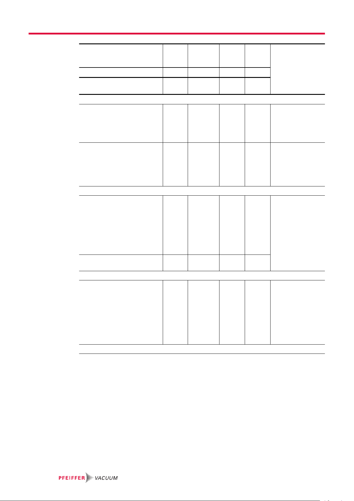
Action Inspec-
tion
described in document OI OI SI SI
Interval daily ≤ 1 year ≤ 1.5
Inspection
Visual and acoustic pump check
●
Check the lubricant level
and color of the lubricant
●
Check the lubricant level of
the sealing oil
●
Check the vacuum pump for
leaks
●
Check the vacuum pump for
running noises
●
Check the overflow valve for
unusual noises
Maintenance level 1
Clean the vacuum pump
●
Pump housing from outside
●
Rinse the suction chamber
with a suitable cleaning
agent adapted to the process
●
Check and clean overflow
valve
●
Change the lubricant and
sealing oil
Maintenance level 2
●
Check the coupling for damage, replace the toothed
ring if necessary
●
Replace radial shaft seal
rings and protective sleeves
(for Roots pumps with a radial shaft seal ring)
●
Clean the gear chambers
and replace the seals
Maintenance level 3
■
■
Maintenance
level 1
■
as re-
quired
■
Maintenance
level 2
years
■ Maintenance kit with
Maintenance
level 3
≤ 3
years
Required material
Lubricant
Suitable cleaning
agent, compatible
with the process
wearing parts of the
coupling and the radial shaft seal rings
32/52
Maintenance
Action Inspec-
tion
described in document OI OI SI SI
Interval daily ≤ 1 year ≤ 1.5
Dismantle and clean the vacuum
pump
●
Replace the seals and all
wearing parts
●
Replace 4 piston bearings
(ball bearings/roller bearings)
●
Replace overflow valve
wear parts
Check critical components and
replace if necessary:
●
Magnetic coupling (check
magnets for damage)
●
temperature sensor (calibrate the sensor with the
reference temperature)
●
gear wheels (check the
teeth for breaks)
Maintenance
level 1
Maintenance
level 2
years
Maintenance
level 3
≤ 3
years
■ Overhaul kit
■
Required material
Lubricant
Option
●
Magnetic coupling set
●
Set of gear
wheels
Tbl. 6: Maintenance intervals
7.3 Changing the lubricant
WARNING
Health hazard and environmental damage from toxic contaminated lubricant
Toxic process media can cause lubricant contamination. When changing the lubricant, there is a
health hazard due to contact with poisonous substances. Illegal disposal of toxic substances causes
environmental damage.
►
Wear suitable personal protective equipment when handling these media.
►
Dispose of the lubricant according to locally applicable regulations.
CAUTION
Scalding from hot lubricant
Danger of scalding when draining lubricant if it comes into contact with the skin.
►
Wear personal protective equipment.
►
Use a suitable collection receptacle.
Pfeiffer Vacuum recommends determining the precise service life of the lubricant in
the first operating year.
The usable life may deviate from the reference value specified depending on thermic and
chemical loads, or due to penetrating process media in gear and bearing chambers.
Safety data sheets
You can obtain the safety data sheets for lubricants from Pfeiffer Vacuum on request, or
from the Pfeiffer Vacuum Download Center.
Consumable
●
Lubricant
33/52
2
9 8
31 4
5
6
7
Maintenance
Required tool
●
Ring spanner, WAF 17 mm
●
Calibrated torque wrench (tightening factor ≤ 2.5)
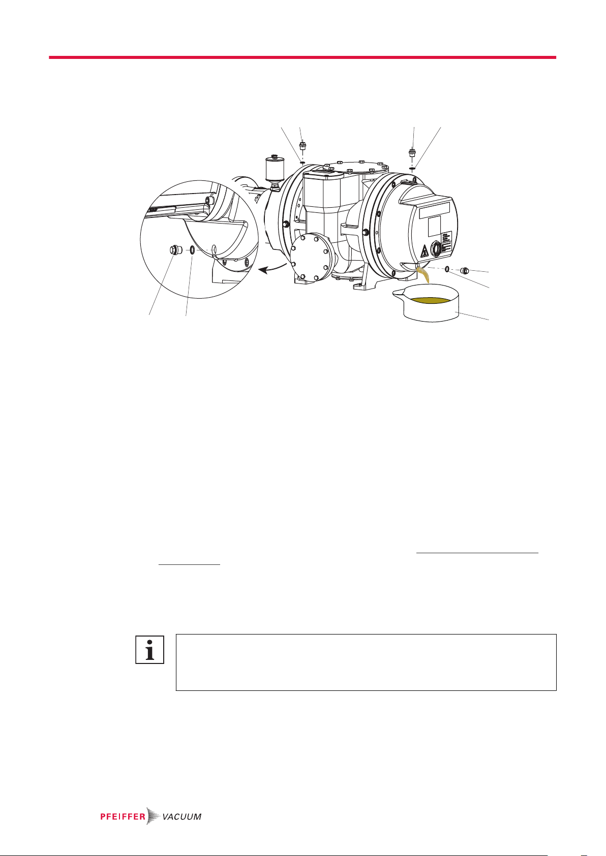
Fig. 10: Drain the lubricant
1 O-ring 6 O-ring
2 Lubricant filling plug 7 Collection receptacle
3 Lubricant filling plug 8 O-ring
4 O-ring 9 Lubricant drain plug
5 Lubricant drain plug
Drain the lubricant
1. Shut down the vacuum pump and allow it to cool if necessary.
2. Vent the vacuum pump to atmospheric pressure via the intake side.
3. Unscrew the lubricant filler screws.
4. Place the collection receptacle underneath.
5. Unscrew both lubricant filler screws.
6. Fully drain the lubricant.
7. Screw the drain screws back in.
–
Tightening torque: max. 32 Nm
Filling with lubricant
1. Fill the lubricant on both sides until the max. fill level is reached (see chapter “Filling with lubri-
cant”, page 20).
2. Screw in the lubricant filler screws again.
–
Tightening torque: max. 32 Nm
7.4 Changing the sealing oil
Overfilling the oiler
The lubricant expands when the roots pump heats up, which could cause lubricant to leak if
overfilled.
Oiler fill level with roots pump in cold state: to max. halfway.
34/52
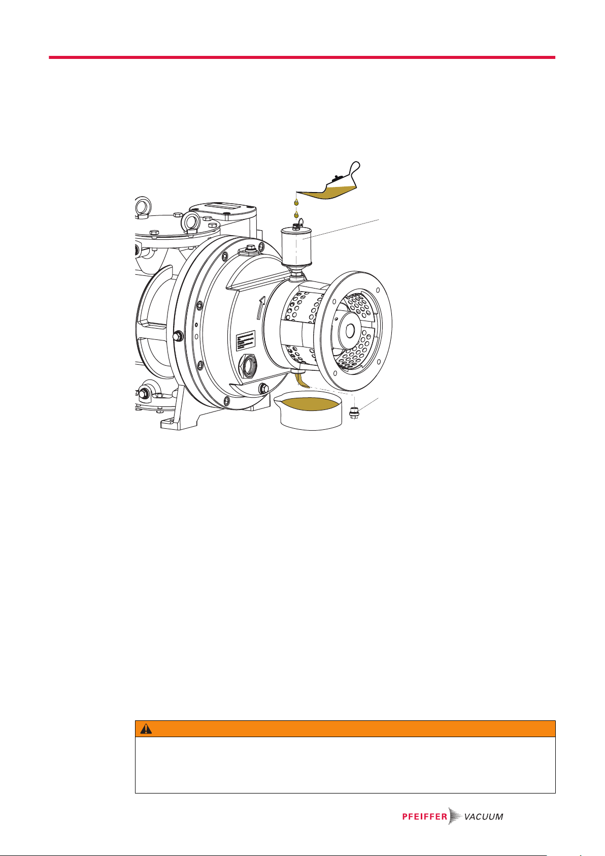
A sealing oil change is required for roots pumps with radial shaft seal ring.
A decreasing oil level in the oiler and an oil leak below the lantern indicate a defective external radial
shaft seal ring. As long as the oil loss on the oiler is compensated, you may continue operating the roots
pump for a certain amount of time.
2
1
Maintenance
Procedure in the event of significant oil loss
A decreasing oil level, with no leaked oil visible below the roots pump, is due to a worn inner radial
shaft seal ring.
►
Should this occur, arrange for maintenance to be carried out by Pfeiffer Vacuum Service, during
which all 3 radial shaft seal rings are generally replaced.
–
This damage leads to an inadmissibly high oil level in the bearing chamber.
Fig. 11:
1 Oiler 2 Sealing oil drain screw
Consumable
●
Required tools
●
●
Procedure for changing sealing oil
1. In general, carry out a sealing oil change once a year.
2. Open the filler flap on the oiler.
3. Place the collection receptacle underneath.
4. Unscrew the sealing oil drain screw.
5. Fully drain the lubricant.
6. Screw the drain screw back in.
7. Fill the oiler with lubricant to max. halfway.
8. Close the filler flap.
Replacing the sealing oil for radial shaft seal rings
Lubricant
Open-end wrench, WAF 17
Calibrated torque wrench (tightening factor ≤ 2.5)
–
Tightening torque: 32 Nm
7.5 Cleaning the suction chamber
WARNING
Risk of crushing from rotating parts
Fingers and hands may be caught by rotating pistons within the connection flange. This results in severe injuries.
►
Keep limbs out of the reach of the roots pump.
35/52
1
2
3
4
5
7
6
9 8
Maintenance
Property damage from incorrect cleaning procedure
Flushing fluid and process media that enters the bearing and oil chambers will stick.
►
During the cleaning processes, always protect all bearings with sealing gas in order to prevent a
contamination of the lubricant and bearing chambers.
The clearance between pistons and housing are within a tenth of a centimeter range. Sustained, accumulating contamination has the following effect:
●
the friction heat inside the roots pump increases
●
the power consumption of the roots pump increases
●
the pistons jam
Procedure
1. Dismantle the pipes from the vacuum and fore-vacuum connections.
2. Clean the suction chamber and the overflow channel with suitable brushes and cleaning agents.
3. After cleaning, completely remove remaining fluids using absorbent materials, and dry the suction
chamber.
4. After cleaning, mount all pipes.
5. Screw in the drain screws.
7.6 Cleaning the overflow valve
NOTICE
36/52
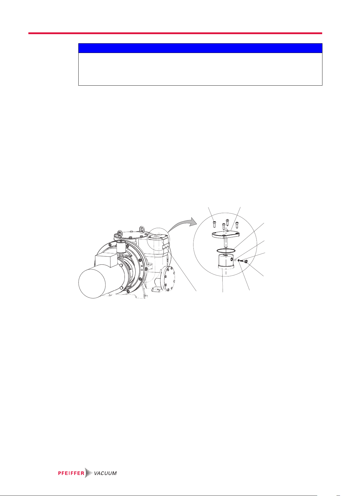
Fig. 12: Overflow valve
1 Allen head screws 6 Pressure screw
2 Valve cover 7 Compression piece
3 O-ring 8 Valve plate
4 Ball 9 Pump housing
5 Compression spring
Required tools
●
Allen key, WAF 6 mm
●
Calibrated torque wrench (tightening factor ≤ 2.5)
Remove the overflow valve
1. Unscrew the screws and remove the valve cover.
2. Be careful with the O-ring.
3. Remove the valve plate from the overflow channel.
4. Unscrew and remove the pressure screw and at the same time remove the compression spring,
compression piece, and ball.
5. Clean and dry the guide pin from the valve cover.
6. Lightly rub the surface with emery cloth (grain size 180).
–
Never oil the guide pins, this has an adverse effect on damping.
–
If necessary, replace completely if there are pronounced traces of wear.
7. Clean the other parts.
8. Inspect all parts for wear and replace if necessary.
Install the overflow valve
32
5
4
6
7
8
E
1
1. Mount the ball, compression piece, and spring.
2. Lock the thread on the pressure screw with Loctite 243.
3. Screw in the pressure screw.
4. Locate the valve plate in the overflow channel.
5. Install the O-ring in the appropriate groove.
6. Place the valve cover on the housing.
7. Tighten the screws crosswise.
–
Tightening torque: 25 Nm
7.7 Installing the coupling
WARNING
Danger of injury due to exposed rotating parts
In the operating range of the motor coupling, there is a danger of clothing being caught and wound
up.
►
When assembling the motor and coupling, make sure that the coupling protection is seated correctly.
►
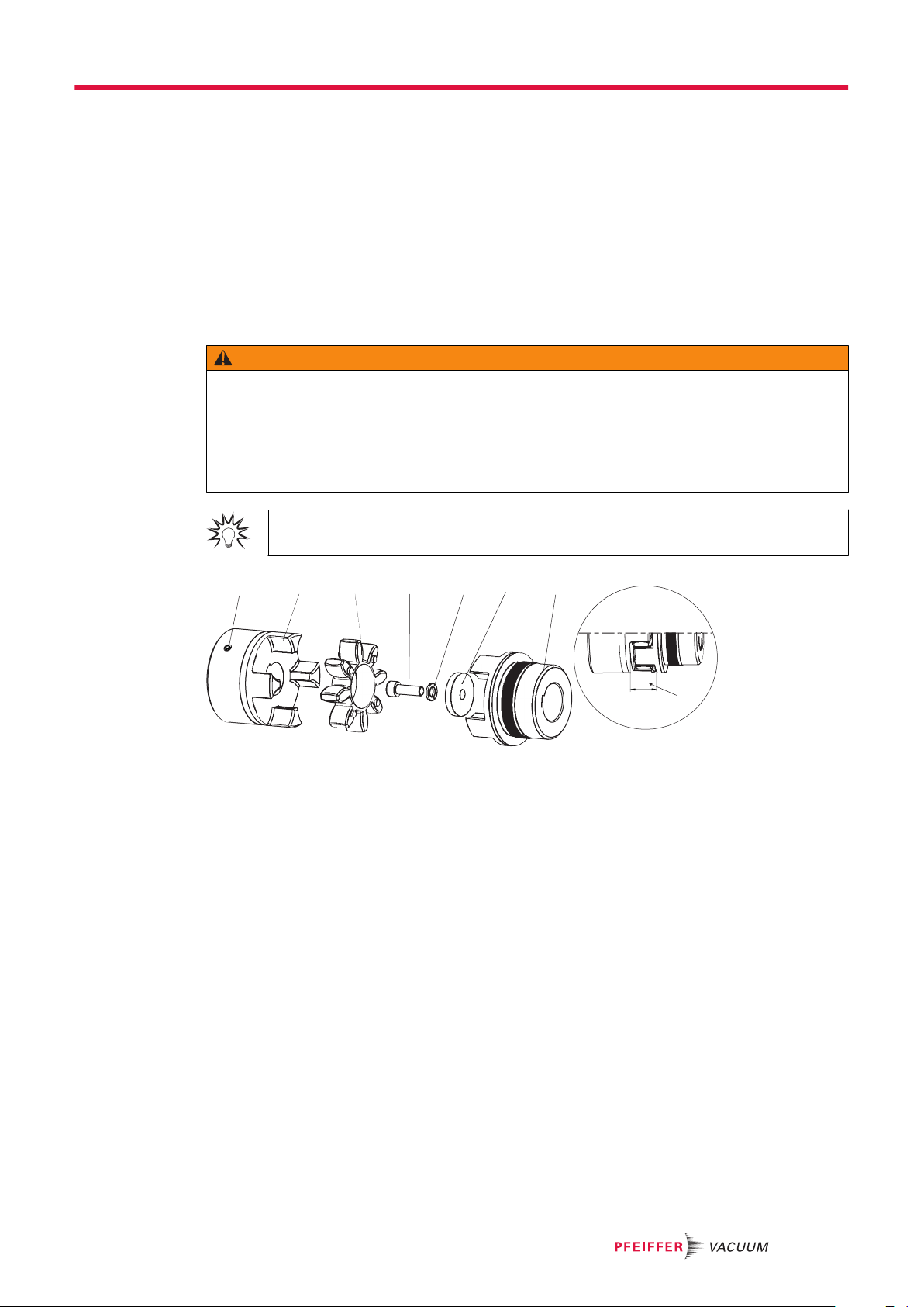
Wear correct clothing.
Coupling assembly
Observe the installation instructions of the coupling manufacturer.
Maintenance
Fig. 13: Installation instructions gear rim coupling
1 Stud screw (TA) 5 Lock washer
2 Coupling half motor 6 Washer
3 Toothed ring coupling hub 7 Coupling half pump side
4 Cheesehead screw (TP) 8 Clearance E
Required tools
●
Allen key, WAF 4 mm
●
Allen key, WAF 6 mm
●
Calibrated torque wrench (tightening factor ≤ 2.5)
Procedure
1. Precisely adhere to the prescribed installation dimensions.
–
Angular and radial displacement of the shafts.
–
Clearance E: 24 mm.
2. Lock the thread on the stud screw with Loctite 243.
3. Tighten the stud screw in the motor side coupling half.
–
Tightening torque TA: 10 Nm
4. Install the pump side coupling half.
5. Lock the thread on the cheesehead screw with Loctite 243.
6. Install the cheesehead screw with washer and spring washer.
–
Tightening torque TP: 32 Nm
37/52
Maintenance
7.8 Installing the coupling for versions with magnetic coupling
WARNING
Danger of injury from strong magnetic field
There is a risk of injury for people with pacemakers and medical implants.
►
Make sure that such individuals do not enter the sphere of influence (≤ 2 m) of the magnetic field.
►
Identify rooms in which magnetic couplings are openly accessible with the symbol: "No access
for people with pacemakers".
►
Always keep disassembled couplings away from computers, data carriers, and other electronic
components.
NOTICE
Damage to the magnetic coupling due to incorrect installation and removal
The isolating shroud on the magnetic coupling is made of impact-sensitive material (synthetic or ceramic).
If the motor is installed or removed incorrectly, there is a risk of damage.
►
Attach the motor to the lifting gear with the eye bolt and pull the motor horizontally away from the
vacuum pump.
►
Use jacking bolts and guide pins.
Supplementary information for work on the magnetic couplings of Roots pumps
Upon request, you can obtain supplementary information PW0142 from Pfeiffer Vacuum
Download Center.
38/52

8 Decommissioning
8.1 Shutting down for longer periods
Before shutting down the vacuum pump, observe the following instructions to adequately protect the interior of the vacuum pump (suction chamber) from corrosion:
Shutting down the vacuum pump
1. Switch off the vacuum pump.
2. Vent the vacuum pump.
3. Allow the vacuum pump to cool down.
4. Clean suction chamber.
5. Change the lubricant.
6. Seal the vacuum and fore-vacuum flanges as well as any other openings with blind flanges from
the Pfeiffer Vacuum accessories range.
7. Evacuatie the pump interior via the measurement connection on the vacuum side to p < 1 hPa.
8. Fill the suction chamber with nitrogen.
9. Store the vacuum pump in dry, dust-free rooms, within the specified ambient conditions.
10. In rooms with damp or aggressive atmospheres, you should package the vacuum pump in a plastic bag together with a drying agent, and seal it so that it is airtight.
11. For storage durations longer than 2 years, we recommend you carry out maintenance and a lubricant change prior to recommissioning.
12. Please note, the vacuum pump may not be stored in the vicinity of machines, traffic routes, etc.,
as strong vibrations may damage the bearing.
Decommissioning
8.2 Recommissioning
Damage to the roots pump due to aging of the lubricant
The useful life of the lubricant is limited (max. 2 years). Prior to recommissioning, following a shutdown of 2 years or more, carry out the following work.
►
Observe the maintenance instructions – consult Pfeiffer Vacuum if necessary.
►
Change the lubricant.
►
Check the bearing and if necessary, change the critical elastomer parts.
Control work before re-commissioning
1. Check the roots pump for visible damage and put the roots pump into operation only if it is in a
correct state.
2. Perform a visual inspection of the pump inner chamber.
3. If drying pearls were inserted in the suction chamber then they should be removed now.
4. If there is evidence of rust on the parts which form the housing then do not put the roots pump into
operation and contact Pfeiffer Vacuum Service.
5. If necessary, subject the roots pump to a leak test before re-commissioning.
8.3 Disposing of the vacuum pump
WARNING
Health hazard through poisoning from toxic contaminated components or devices
Toxic process media result in contamination of devices or parts of them. During maintenance work,
there is a risk to health from contact with these poisonous substances. Illegal disposal of toxic substances causes environmental damage.
►
Take suitable safety precautions and prevent health hazards or environmental pollution by toxic
process media.
►
Decontaminate affected parts before carrying out maintenance work.
►
Wear protective equipment.
NOTICE
39/52

Decommissioning
Procedure
►
Dispose of all substances safely according to local regulations.
40/52
9 Malfunctions
CAUTION
Danger of burns on hot surfaces
In the event of a fault, the surface temperature of the vacuum pump can increase to above 105°C.
►
Allow the vacuum pump to cool down before working on it.
►
Wear personal protective equipment if necessary.
Danger of property damage from improper maintenance
Unprofessional work on the vacuum pump will lead to damage for which Pfeiffer Vacuum accepts no
liability.
►
We recommend taking advantage of our service training offering.
►
When ordering spare parts, specify the information on the nameplate.
Problem Possible causes Remedy
Vacuum pump will not
start up
Vacuum pump switches
off after a while after being started
Vacuum pump/pumping
station does not reach
ultimate pressure
Malfunctions
NOTICE
●
Mains voltage is missing
or the incorrect operating
voltage is present
●
Thermal protection switch
has triggered
●
Suction chamber contaminated
●
Gear (gear wheels) damaged
●
Bearing damage present 1. Have the bearing changed.
●
Motor faulty 1. Change the motor.
●
Thermal protection switch
of the motor has triggered
●
Fore-vacuum pressure
possibly too high
●
Suction chamber dirty 1. Clean suction chamber.
●
Lubricant soiled 1. Change the lubricant.
●
Backing pump operates
incorrectly
●
Leak in system 1. Examine the system for leaks and, if
●
Loss of lubricant at the lubricator or the radial shaft
seal rings
1. Check the mains voltage.
2. Check the mains fuse.
3. Check the motor switch.
1. Determine the cause and eliminate
the fault.
2. Allow the vacuum pump to cool if
needed.
1. Clean suction chamber.
2. If necessary, contact Pfeiffer Vacuum Service.
1. Switch off the vacuum pump immediately.
2. If necessary, contact Pfeiffer Vacuum Service.
2. Contact Pfeiffer Vacuum Service.
1. Determine the cause of the overheating and eliminate the fault.
2. Check the fore-vacuum pressure.
3. Allow the motor to cool if necessary.
1. Check the backing pump.
necessary, carry out a leak test.
2. Eliminate leaks.
1. Check the radial shaft seal rings.
2. Have the radial shaft seal rings replaced if necessary.
3. If necessary, contact Pfeiffer Vacuum Service.
41/52

Malfunctions
Problem Possible causes Remedy
Unusual noises during
operation
●
Suction chamber dirty 1. Switch off the vacuum pump imme-
diately.
2. Clean suction chamber.
●
Damage to the bearing or
gear wheels
●
Overflow valve soiled 1. Switch off the vacuum pump imme-
●
Damage to motor bearing 1. Switch off the vacuum pump imme-
Only applies to vacuum
pumps with magnetic coupling
●
Motor is running – vacuum
pump is not working, i.e.,
the magnetic coupling is
defective or the magnetic
field has broken down.
If the vacuum pump continues to run with a "broken down" magnetic field,
the magnetic coupling is
destroyed by demagnetization.
1. Switch off the vacuum pump immediately.
2. Contact Pfeiffer Vacuum Service.
diately.
2. Clean the overflow valve.
diately.
2. Change the motor.
3. If necessary, contact Pfeiffer Vacuum Service.
1. Switch off the vacuum pump immediately.
While the vacuum pump is at a
standstill, the magnets can realign
with each other.
2. Slowly restart the vacuum pump and
check the power transmission and
vacuum pressure.
Tbl. 7: Troubleshooting
42/52

ANFORDERUNG SERVICE
ERKLÄRUNG KONTAMINIERUNG
Service solutions from Pfeiffer Vacuum
10 Service solutions from Pfeiffer Vacuum
We offer first class service
Long vacuum component service life, coupled with low downtimes, are clear expectations that you have
of us. We satisfy your needs with capable products and outstanding service.
We are consistently striving to perfect our core competence, service for vacuum components. And our
service is far from over once you’ve purchased a product from Pfeiffer Vacuum. It often enough really
just begins then. In proven Pfeiffer Vacuum quality, of course.
Our professional sales engineers and service technicians stand ready to provide hands-on support to
you worldwide. Pfeiffer Vacuum offers a complete portfolio of service offerings, ranging from genuine
spare parts right through to service agreements.
Take advantage of Pfeiffer Vacuum Service
Whether for preventative on-site service from our field service, fast replacement with as-new replacement products or repair in a Service Center close to you; you have various options for upholding your
equipment availability. Detailed information and addresses can be found on our website in the Pfeiff-
er Vacuum Service section.
Advice on the optimum solution is available from your Pfeiffer Vacuum contact partner.
For quick and smooth handling of the service process, we recommend the following steps:
1.
Download the current form templates.
─
Declaration of Service Request
─
Service Request
─
Declaration of Contamination
a.
Dismantle all accessories and keep them (all external mounted parts as
valve, inlet screen, etc.).
b.
Drain the operating fluid/lubricant as necessary.
c.
Drain the cooling medium as necessary.
2.
Fill out the service request and the declaration of contamination.
3.
Send the forms via email, fax or post to your local Service Center.
4.
You will receive a response from Pfeiffer Vacuum.
Sending of contaminated products
No units will be accepted if they are contaminated with micro-biological, explosive or radioactive substances. If products are contaminated or if the declaration of contamination is missing, Pfeiffer Vacuum
will contact the customer before starting maintenance. In addition, depending on the product and the
level of contamination additional decontamination costs may be required.
43/52

ERKLÄRUNG KONTAMINIERUNG
Service solutions from Pfeiffer Vacuum
5.
Prepare the product for transport in accordance with the details in
the declaration of contamination.
a)
Neutralize the product with nitrogen or dry air.
b)
Close all openings with airtight blank flanges.
c)
Seal the product in appropriate protective film.
d)
Only pack the product in suitable, stable transport containers.
e)
Observe the applicable transport conditions.
6
Affix the declaration of contamination to the outside of the packaging.
7
Then send your product to your local Service Center.
8
You will receive a confirmation message/a quotation from Pfeiffer Vacuum.
For all service orders, our General Terms and Conditions of Sales and Supply and General Terms and
Conditions of Repair and Maintenance apply to vacuum equipment and components.
44/52

11 Spare parts
►
Have the vacuum pump part number, and any other necessary details from the rating plate, at
hand when ordering spare parts.
►
Only use original spare parts.
Article no. of vacuum pump Pump type Set of seals Maintenance kit
PP W41 000 – 020 Okta 1000 PP E10 006 -T PP E11 005 -T
PP W41 700 – 720 Okta 1000 PP E10 007 -T PP E11 005 -T
PP W42 000 – 020 Okta 1000 M PP E10 024 -T PP E11 010 -T
PP W42 700 – 020 Okta 1000 M PP E10 024 -T PP E11 010 -T
Tbl. 8: Available spare parts packages
11.1 Set of seals for version with RSSR
The set of seals contains:
●
all sealing parts such as O-rings, radial shaft seal rings and supporting rings
●
flat seals, square washers and annular profile seals
The protective sleeve and centering rings for connecting the roots pump to the suction and pressure
sides are not included.
Spare parts
11.2 Set of seals for version with magnetic coupling
The set of seals contains:
●
all sealing parts such as O-rings
●
flat seals, square washers and annular profile seals
Centering rings for connecting the suction and pressure sides are not included.
11.3 Maintenance kit for version with RSSR
The maintenance kit contains:
●
all sealing parts in the area of the radial shaft seal ring including the protective sleeve
●
all sealing rings of the filling and drain screws and both O-rings for the device cover and cap
●
the coupling buffer (toothed ring)
11.4 Maintenance kit for version with magnetic coupling
The maintenance kit contains:
●
all sealing rings of the filling and drain screws and both O-rings for the device cover and cap
●
the O-ring for the isolation shroud
45/52

Accessories
12 Accessories
View the line of accessories for Pfeiffer Vacuum roots pumps online at pfeiffer-vacuum.de.
12.1 Sealing gas device
The use of sealing gas at the bearing points protects the lubricant from contamination by the ingress of
process media and flushing fluid into the bearing and oil chambers.
12.2 Flushing device
The flushing device is used to clean the materials in contact with the medium if the extracted medium
polymerizes or deposits in the suction chamber.
12.3 Gear space extraction
The gearbox housing extractor serves to evacuate the gear and bearing chambers in order to shorten
pump downtime. The gearbox chamber extractor prevents foaming of the operating resource during
pronounced pressure changes.
12.4 Protective strainer
The protective strainer on the vacuum connection prevents solids from penetrating into the suction
chamber of the vacuum pump.
46/52

13 Technical data and dimensions
13.1 General
Basis for the technical data of Pfeiffer Vacuum roots pumps
●
Specifications according to PNEUROP committee PN5
●
DIN ISO 21360-1: 2016 “Vacuum technology - Standard methods for measuring vacuum-pump
performance - General description”
●
Integral leakage rate with 20 % helium concentration, 10 s measurement duration
●
Sound pressure level: distance to vacuum pump 1 m
mbar bar Pa hPa kPa Torr | mm Hg
mbar 1
bar 1000 1
Pa 0.01
hPa 1
kPa 10 0.01 1000 10 1 7.5
Torr | mm Hg 1.33
-3
1 · 10
-5
1 · 10
-3
1 · 10
1.33 · 10
-3
1 Pa = 1 N/m
100 1 0.1 0.75
1 · 10
1 0.01
100 1 0.1 0.75
133.32 1.33 0.133 1
Technical data and dimensions
5
1000 100 750
1 · 10
2
-3
7.5 · 10
-3
Tbl. 9: Conversion table: Pressure units
mbar l/s 1 0.1 59.2 0.75 0.987
Pa m3/s
sccm
Torr l/s 1.33 0.133 78.9 1 1.32
atm cm3/s
Tbl. 10: Conversion table: Units for gas throughput
13.2 Technical data
Classification Okta 1000 Okta 1000 M
Version Standard with motor Standard with motor and
Differential pressure at the overflow valve 45 hPa 45 hPa
Flange (in) DN 160 ISO-F DN 160 ISO-F
Flange (out) DN 100 ISO-F DN 100 ISO-F
Nominal pumping speed 590 – 1 775 m³/h 590 – 1 775 m³/h
Nominal pumping speed at 50 Hz 1180 m³/h 1180 m³/h
Nominal pumping speed at 60 Hz 1420 m³/h 1420 m³/h
Input voltage 50 Hz 230 / 400 V 230 / 400 V
Input voltage 60 Hz 265 / 460 V 265 / 460 V
Input voltage: tolerance ±5 % ±5 %
Rated power 50 Hz 3 kW 3 kW
Rated power 60 Hz 3.5 kW 3.5 kW
mbar l/s
Pa m3/s
sccm Torr l/s
atm cm3/s
10 1 592 7.5 9.87
1.69 · 10
-2
1.69 · 10
-3
1
1.27 · 10
-2
1.67 · 10
1.01 0.101 59.8 0.76 1
magnetic coupling
-2
47/52
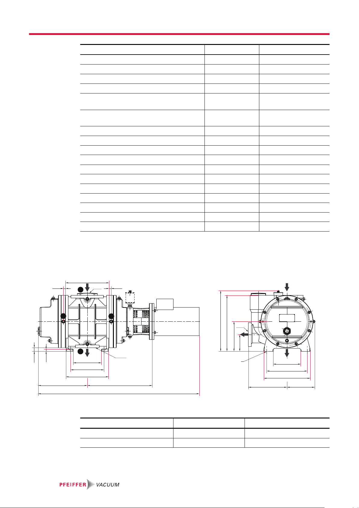
DN1
190
280
320
D 192
115
205
385
C
Ø11 (4x)
194
230
294
339
B
A
15
25
300
1515
DN3
DN2
V
VV
SG
SG
Technical data and dimensions
Classification Okta 1000 Okta 1000 M
Nominal rotation speed at 50 Hz 3000 rpm 3000 rpm
Nominal rotation speed at 60 Hz 3600 rpm 3600 rpm
Rotation speed 1 500 – 4 500 rpm 1 500 – 4 500 rpm
Leak rate
Emission sound pressure level (EN ISO 2151) at
intake pressure 10 hPa
Emission sound pressure level (EN ISO 2151) at
intake pressure 1 hPa
Protection category IP55 IP55
Cooling method, standard Air Air
Motor protection 3TF 3TF
Pumping speed range
Operating fluid filling 2.9 l 2.9 l
DN 1 DN 160 ISO-F DN 160 ISO-F
DN 2 DN 100 ISO-F DN 100 ISO-F
DN 3 DN 100 ISO-F DN 100 ISO-F
Ambient temperature 5 – 40 °C 5 – 40 °C
Transport and storage temperature -10 °C – 40 °C -10 °C – 40 °C
Weight: with motor 240 kg 275 kg
1 · 10-3 Pa m³/s 1 · 10-6 Pa m³/s
75 dB(A) 75 dB(A)
72 dB(A) 72 dB(A)
1000 m3/h 1000 m3/h
Tbl. 11: Technical data Okta 1000 Standard | M
13.3 Dimensions
Dimensions in mm
Fig. 14: Dimension diagram Okta 1000 Standard | M
Classification Okta 1000 Okta 1000 M
A 1112 mm 1125 mm
B 448 mm 461 mm
48/52

Technical data and dimensions
Classification Okta 1000 Okta 1000 M
C 418 mm 402 mm
D 266 mm 266 mm
Tbl. 12: Dimensions Okta 1000 Standard | M
49/52
Declaration of conformity
We hereby declare that the product cited below satisfies all relevant provisions of the following EC Directives:
●
Machinery 2006/42/EC (Annex II, no. 1 A)
●
Electromagnetic compatibility 2014/30/EU
●
Restriction of the use of certain hazardous substances 2011/65/EU
The authorized representative for the compilation of technical documents is Mr. Sebastian Oberbeck, Pfeiffer Vacuum GmbH, Berliner Straße 43, 35614 Aßlar, Germany.
Roots pump
Okta 1000
Okta 1000 M
Harmonized standards and applied national standards and specifications:
DIN EN ISO 12100: 2011 DIN EN 61010-1: 2011
DIN EN 1012-2: 2011-12 DIN EN 61000-3-11
DIN EN ISO 13857: 2008 DIN EN 61000-3-12
DIN ISO 21360-1 : 2016 DIN EN 61000-6-2: 2006
ISO 21360-2 : 2012 DIN EN 61000-6-4: 2007
DIN EN ISO 2151: 2009 DIN EN 60529 : 2014
DIN EN 60204-1 : 2014
Signature:
(Dr. Ulrich von Hülsen)
Managing Director
Pfeiffer Vacuum GmbH
Berliner Straße 43
35614 Asslar
Germany
Asslar, Germany,
2019-02-16

51/52
ed. S - Date 1903 - P/N:PP0950BEN
*PP0950*
 Loading...