

Page 1

-900/56
-900/61
296-12-14 827
Justieranleitung engl. 06.95
Service Manual
for 440-R, 1440, 420
and 1420
series machines
Page 2

2
Adjustment
11 Safety ............................................................................................. 34
11. 01 General notes on safety..................................................................................... 34
11.02 Safety symbols .................................................................................................. 44
11. 03 Important points for the user ............................................................................. 44
11. 0 4 Operating and specialist personnel .................................................................... 44
11.04.01 Operating personnel .......................................................................................... 44
11.04.02 Specialist personnel ........................................................................................... 54
11. 05 Warning ............................................................................................................. 54
12 Adjustment ...................................................................................... 64
12. 01 Tools, gauges and other accessories ................................................................. 64
12. 02 Notes on the adjustments ................................................................................. 64
12. 03 Abbreviations ..................................................................................................... 64
12. 04 Explanation of the symbols................................................................................ 6#
13 Tension release trip ........................................................................... 7#
14 Solenoid bracket ............................................................................... 81
14. 0 1 Solenoid bracket on -900/56............................................................................... 81
14. 0 2 Solenoid bracket on -900/61............................................................................... 91
15 Engaging lever pin ............................................................................ 10
16 Eccentric pin of catcher control lever on -900/61 only ............................. 11
17 Control cam and locking bracket ......................................................... 12
17. 01 Axial position of crank lever ............................................................................... 12
17. 02 Radial position of control cam............................................................................ 13
17. 03 Locking bracket.................................................................................................. 14
18 Engaging solenoid ............................................................................ 15
19 Stop lug .......................................................................................... 16
10 Catcher actuating lever ...................................................................... 17
11 Catcher connecting rod (two-needle machines) ..................................... 18
12 Catcher height .................................................................................. 19
13 Thread catcher rest position ............................................................... 20
14 Knife height ..................................................................................... 21
15 Knife pressure .................................................................................. 22
16 Bobbin thread trapper spring .............................................................. 23
17 Needle thread tension release ............................................................ 24
18 Synchronisizer.................................................................................. 25
19 Manual trimming test ........................................................................ 26
Contents
Page 3

3
Adjustment
1 Safety
1.01 General notes on safety
● This machine may only be operated by adequately trained operators and only after having
completely read and understood the Instruction Manual.
● All Notes on Safety and Instruction Manuals of the motor manufacturer are to be read
before operating the machine!
● Pay attention to all warnings and safety instructions mounted on the machine!
● This machine may only be used for the purpose for which it is intended and may not be
operated without its safety devices. All Safety Regulations relevant to its operation are to
be adhered to.
● When exchanging sewing tools (e.g. needle, presser foot, needle plate, feed dog or
bobbin), when threading the machine, when leaving the machine unattended and during
maintenance work, the machine is to be separated from the power supply by switching
off the On/Off switch or by removing the plug from the mains!
● Everyday maintenance work is only to be carried out by appropriately trained personnel!
● Repairs and special maintenance work may only be carried out by qualified service staff
or appropriately trained personnel.
● When servicing or carrying out repairs on pneumatic devices, the machine is to be
removed from the compressed air supply. The only exceptions to this are adjustments
and function checks carried out by appropriately trained personnel!
● Work on electrical equipment may only be carried out by appropriately trained personnel!
● Work is not permitted on parts and equipment which are connected to the power
supply. Exceptions to this are in accordance with the regulations EN 50110.
● Modifications and alterations to the machine may only be carried out under observance
of all the relevant safety regulations!
● Only spare parts which have been approved by us are to be used for repairs!
We expressly point out that any replacement parts or accessories which are not supplied
by us have not been tested and approved by us. The installation and / or use of any such
products can lead to negative changes in the construction characteristics of the machine.
We shall not be liable for any damage which may be caused by non-original parts.
Safety
Page 4

4
Adjustment
1.02 Safety symbols
Danger!
Points to be observed.
Danger of injury for operating and specialist personnel!
1.03 Important points for the user
● This Instruction Manual is a component part of the machine and must be available to the
operating personnel at all times.
The Instruction Manual must be read before operating the machine for the first time.
● The operating and specialist personnel is to be instructed as to the safety equipment of
the machine and regarding safe work methods.
● It is the duty of the operator to only operate the machine in perfect running order.
● It is the obligation of the operator to ensure that none of the safety mechanisms are
removed or deactivated.
● It is the obligation of the operator to ensure that only authorised persons operate and
work on the machine.
Further information can be obtained at your PFAFF agent.
1.04 Operating and specialist personnel
1.04.01 Operating personnel
Operating personnel are persons responsible for the equipping, operating and cleaning of the
machine as well as taking care of faults arising in the sewing area.
The operating personnel is obliged to observe the following points and must:
● always observe the Notes on Safety in the Instruction Manual!
● never use any working methods which could limit the level of safety in using the
machine!
● not wear loosely fitting clothing or jewellery such as chains or rings!
● also ensure that only authorised persons have access to the potentially dangerous area
around the machine!
● always immediately report to the person responsible any changes in the machine which
may limit its safety!
Safety
Page 5

5
Adjustment
1.04.02 Specialist personnel
Specialist personnel are persons with a specialist education in the fields of electrics,
electronics and mechanics. They are responsible for the lubrication, maintenance, repair and
adjustment of the machine.
The specialist personnel is obliged to observe the following points and must:
● always observe the Notes on Safety in the Instruction Manual!
● switch off the On/Off switch before carrying out adjustments or repairs and ensure that
it cannot be switched on again unintentionally!
● never work on parts which are still connected to the power supply. Exceptions are
contained in the regulations EN 50110.
● when servicing or carrying out repairs on pneumatic devices, remove the machine from
the compressed air supply. The only exceptions to this are function checks.
● replace the protective coverings and close the electrical control box after all repairs or
maintenance work!
1.05 Warning
While sewing keep your hands away from the needle area!
Danger of injury by the needle!
When making adjustments do not leave any objects on the tabletop or
in the needle plate area! Objects could become clamped or slung away!
Danger of injury!
To adjust this unit the machine must be tipped to the back!
Use both hands when setting the machine upright! Danger of clamping
between machine and tabletop!
Safety
Page 6

6
Adjustment
2 Adjustment
Special attention should be payed to the following
This service manual is valid for the subclasses -900/56 and -900/61 for the PF AFF 440-R;
1440; 420 and 1420 series of machines.
The PFAFF 442-R two needle version is illustrated.
The text refers to the single needle version. Notice of additional adjustments for the two
needle machines are marked as such in the corresponding sections. Deviations in the
illustration have no influence on the adjustments.
2.01 Tools, gauges and other accessories
● Screwdrivers with blade width from 2 to 10 mm
● Wrenches from 7 to 14 mm (across flats)
● Hexagon keys, 1.5 to 6 mm
● Metal rule (Part No. 08-880 218-00)
● Continuity tester
● Sewing thread and test material
● Feeler gauge
2.02 Notes on the adjustments
All adjustments in this manual apply to the fully assembled machine. Machine covers which
have to be removed and re-fitted for checks and adjustments are not mentioned in the text.
Screws or nuts in brackets ( ) must be loosened before an adjustment and tightened again
afterwards.
2.03 Abbreviations
t.d.c. = top dead center
b.d.c. = bottom dead center
2.04 Explanation of the symbols
Note, information
Servicing, adjustment
Page 7
7
Adjustment
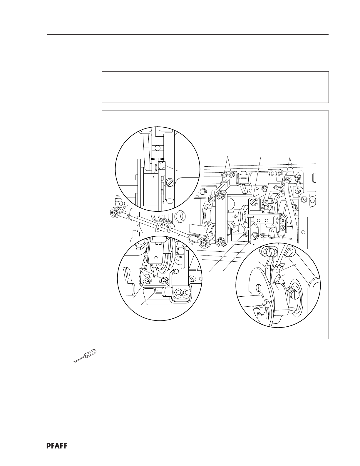
3 Tension release trip
6
3
9
7
2
4
3
2
1
1 mm
● Remove solenoid bracket 1 (screws 2)
● Loosen screws 3 and for more extensive adjustments, also screws 4.
● Turn balance wheel until the widest part of trip 5 is aligned with tension release trip 6.
● Adjust lateral position of stop finger 7 according to the requirement.
● In this position, make sure that stop finger 7 is in contact with bracket 8, move bracket 9
of release trip fully to left in elongated hole and tighten both screws 3.
● Check this adjustment according to the requirement.
● If more extensive adjustments are to be made, screws 4 should remain loose until the
catcher actuating lever is adjusted.
● For adjusting the solenoid bracket 1 only lightly tighten screws 2 (chap. 4).
5
7
5
8
6
Requirement
When the broadest partof trip 5 is aligned with tension trip 6, with the control cam in
resting position and the presser foot lowered, there must be a clearance of roughly 1 mm
between the left side of trip 5 and tension release trip 6.
Page 8
8
Adjustment
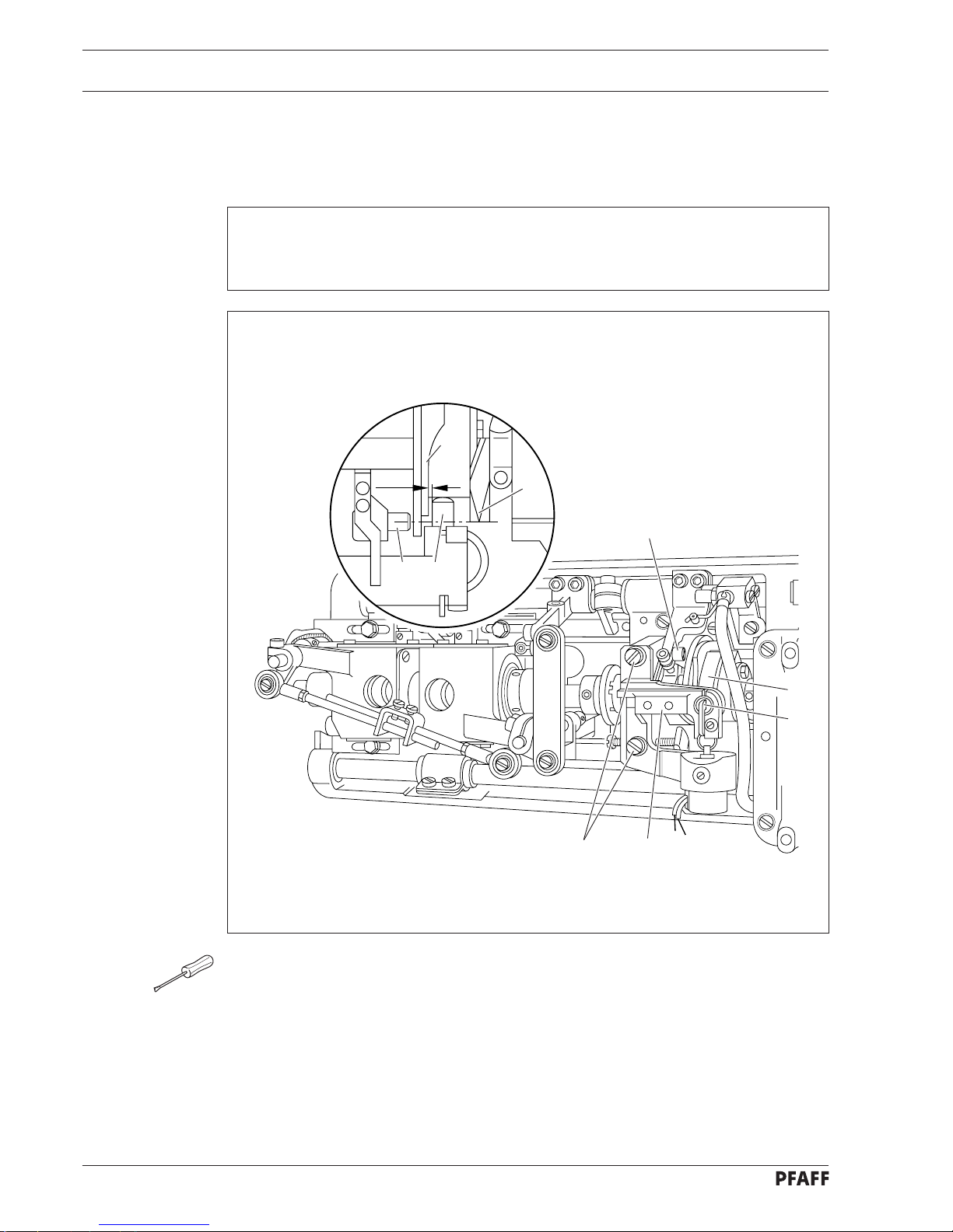
4 Solenoid bracket
4.01 Solenoid bracket on -900/56
● Turn balance wheel until tip of trip 1 is aligned with control pin 2.
● Operate engaging lever 3.
● Loosen both screws 4.
● Adjust position of solenoid bracket 5 according to the requirement
● In this position, tighten screws 4.
● Check this adjustment according to the requirement.
● Turn balance wheel opposite feeding direction until control pin 6 is retained.
2
7
3
54
7
1
6
Requirement
When the tip of trip 1 is aligned with control pin 2 and the engaging lever has been
operated, there must be a clearance of roughly 0.5 mm between the left inside of control
cam 7 and control pin 6.
0.5 mm
2
Page 9
9
Adjustment
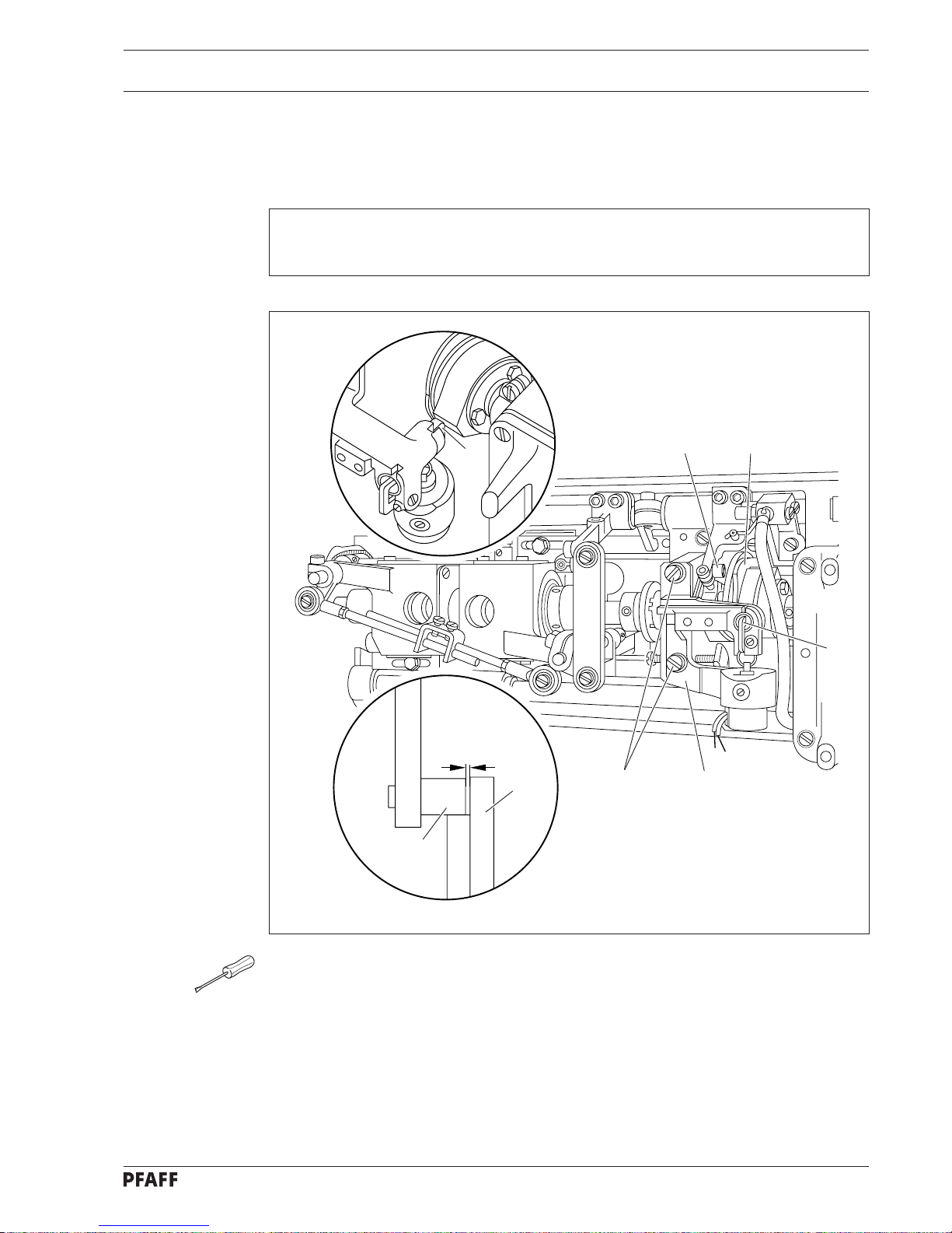
4.02 Solenoid bracket on -900/61
● Turn balance wheel in feeding direction until needle bar is positioned 10 mm before b.d.c.
● Operate engaging lever 1.
● Continue turning balance wheel until control pin 2 is positioned opposite return motion
cam 3.
● Loosen screws 4.
● Adjust position of solenoid bracket 5 according to the requirement.
● In this position, tighten screws 4.
● Check this adjustment according to the requirement.
● Turn balance wheel opposite feeding direction until control pin 6 is retained.
3
2
4
6
2
3
5
0.5 mm
1
Requirement
With engaging lever 1 operated, and control pin 2 positioned beside return motion cam 3,
there must be a clearance of 0.5 mm between control pin 2 and return motion cam 3.
Page 10

10
Adjustment
5 Engaging lever pin
Requirement
When the trimming mechanism is at rest there must be a clearance of 0.1 mm between
the highest point of cam track 1 and control pin 2.
● Make sure control cam 1 is in its starting position. Then turn balance wheel until highest
point of cam track 1 is aligned with control pin 2.
● Loosen screw 3.
● Turn eccentric stud 4 according to the requirement.
● In this position, tighten screw 3.
● Check this adjustment according to the requirement.
4
1
0.1 mm
1
3
2
Page 11

11
Adjustment
6 Eccentric pin of catcher control lever on -900/61 only
● Turn balance wheel in feeding direction until needle bar is positioned 10 mm before b.d.c.
● Operate engaging lever 1.
● Continue turning balance wheel until control pin 2 has moved control cam 3 to its left
reversal point.
● Retaining this position, loosen screw 5 and turn eccentric pin 4 according to the
requirement.
● In this position, tighten screw 5.
● Chec k this adjustment according to the requirement and repeat, if necessary.
Requirement
Over the entire cam circumference the roller of eccentric pin 4 must be as close to control
cam 3 as possible.
1
3
2
4
5
3
x
Page 12

12
Adjustment
7 Control cam and locking bracket
7.01 Axial position of crank lever
● Turn balance wheel in feeding direction until needle bar is positioned 10 mm bef ore b.d.c.
● Loosen screw 1 just sufficiently for crank lever 2 to be moved on its shaft against
resistance.
● Operate engaging lever 3.
● Continue turning balance wheel until control pin 4 has set control cam 5 at its left point of
reversal.
● Retain this position, then move crank lever 2 laterally according to the requirement.
● Turn balance wheel in feeding direction until needle bar is positioned 10 mm bef ore b.d.c.
● Tighten screw 1.
● Make sure control cam 5 is just about to snap back to starting position, then push it all
way to left. As you continue turning balance wheel, return motion cam 6 must freely pass
stud 7.
If required, repeat solenoid bracket adjustments (chap.4).
7
6
5
3
1
2
8
4
0.2 mm
Requirement
Operate engaging lever 3 and turn the balance wheel to set control cam 5 at its far left
position; there must then be a clearance of 0.2 mm between guide finger 8 and bottom of
the control cam cutout (see below).
Page 13

13
Adjustment
7.02 Radial position of control cam
3
2
● Adjust guide finger 1 (screw 2) according to the requirement without mo ving it axially.
2
1
Requirement
When the take-up lever is at t.d.c., the trimming action must be completed and control cam
3 must spring back to its starting position.
Page 14

14
Adjustment
7.03 Locking bracket
➤
➤
➤
3
4
2
65
1
4
0.5 mm
● Turn balance wheel in feeding direction until needle bar is positioned 10 mm bef ore b.d.c.
● Operate engaging lever 1.
● Continue turning balance wheel in feeding direction until needle bar is positioned at t.d.c.
● Loosen screws 2 on locking bracket 3.
● Push control cam 4 all way to left by hand.
● Retaining this position, set clearance between control cam 4 and locking
bracket 3 according to the requirement.
● Tighten screws 2.
● Loosen nut 5 and bring screw 6 into contact with locking bracket 3.
● Tighten nut 5.
● Check this adjustment according to the requirement.
Requirement
With control cam 4 guided to the left and pushed to the left by hand and the needle bar at
t.d.c. there must be a clearance of 0.5 mm between locking bracket 3 and control cam 4.
Page 15

15
Adjustment
8 Engaging solenoid
Requirement
With the needle bar positioned 10 mm before b.d.c. and engaging lever 2 operated, core 4
of the engaging solenoid must have a play of 1 mm.
● Turn balance wheel in feeding direction until needle bar is positioned 10 mm before
bottom dead centre.
● Loosen screw 1.
● Operate engaging lever 2.
● Push solenoid housing 3 upwards until solenoid core 4 is fully inside housing.
● In this position, make a mark on solenoid housing 3 immediately below solenoid bracket 5.
● Push solenoid housing 3 downwards by 1 mm and tighten screw 1.
● Check this adjustment according to the requirement.
2
4
5
3
1
1 mm
Page 16

16
Adjustment
9 Stop lug
Requirement
With stud 5 positioned at the highest point of disengaging cam 4 (take-up lever shortly
before t.d.c.) there must be a clearance of 0.1 mm between stop lug 7 and the bedplate.
● Turn balance wheel in feeding direction to set needle bar 10 mm before b.d.c.
● Operate engaging lever 1.
● Loosen screws 2, then loosen screw 3.
● Turn balance wheel to position highest point of disengaging cam 4 under stud 5 of
catcher control lever 6 (shortly before control cam returns to starting position).
● Maintaining this position, set stop 7 according to the requirement.
● Tighten screw 3.
● Check this adjustment according to the requirement.
2 3
6
4
1
5
6
0.1 mm
7
Page 17

17
Adjustment
➤
10 Catcher actuating lever
● Loosen nut 1.
● Set ball-joint connecting link 2 in centre of elongated hole in crank 3.
● Tighten nut 1.
● Making sure trimming mechanism is at rest and screws 4 are still loose, loosen screws 5.
● Adjust catcher actuating lever 6 both axially and radially according to the requirement.
● In this position, tighten screws 4.
● Check this adjustment according to the requirement.
● Screws 5 are left loose for adjustment of thread catcher.
6
2
7
5
1
4
3
9 mm
Requirement
With the trimming mechanism at rest, ball-joint connecting link 2 must be at right angles to
the edge of the bedplate. Also, there must be a clearance of 9 mm between the left edge
of ball-joint connecting link 2 and the centre of catcher driving shaft 7.
When difficult threads are processed and the catcher does not take up the bobbin
thread reliably, the stroke of the catcher can be increased or decreased through the
elongated hole in crank 3.
Page 18

18
Adjustment
11 Catcher connecting rod (two-needle machines)
Requirement
The left bell-crank lever 4 must be parallel to the right bell-crank lever 5.
● Make sure control cam 1 is in starting position and loosen screws 2.
● Adjust catcher connecting rod 3 according to the requirement.
● In this position, tighten screws 2.
4
3
1
2
5
Page 19

19
Adjustment
12 Catcher height
Requirement
Thread catcher 5 must pass 0.8 mm above bobbin case 6.
If during a manual trimming test (chap. 19) the end of the thread catcher pushes
against the bobbin thread, change height setting.
●Making sure that screws 1 are still loose, loosen screw 2.
●Loosen screws 3 in collar 4.
●Swing thread catcher 5 by hand to center it above bobbin case 6, and adjust it according
to the requirement.
●In this position, tighten screw 2.
●Center vertical play of catcher driving lever 7, making sure catcher driving joint is not
strained.
●Maintain position and making sure that collar 4 does not strike other parts, move fully
downwards and tighten screw 3.
●Check this adjustment according to the requirement.
●On two-needle machines, make adjustment twice. Screws 1 are left loose.
1
7
7
43
0.8 mm
6
5
143
2
➤
➤
2
5
5
re
In
sc
C
O
Page 20

20
Adjustment
1
1
2
4
2
4
-900/56
-900/61
0.5 mm
0.5 mm
3
13 Thread catcher rest position
Requirement
When the trimming mechansim is at rest, the triangular cutting tip of catcher 2 must be
positioned 0.5 mm behind the cutting edge of knife 4.
● Make sure trimming mechanism is in starting position and screws 1 are loose, then
swing thread catcher 2 by hand according to the requirement.
● Maintain position while moving crank 3 against its stop and tighten screws 1.
● Check this adjustment according to the requirement.
● On two-needle machines, make adjustment twice.
3
Page 21

21
Adjustment
14 Knife height
Requirement
With the thread trimmer in starting position the upper edge of knife 1 and catcher 2 should
be of equal height.
● The distance plates, part no. 91-141 402-05 (thickness 0.5 mm) should be placed under
the knife 1 for to adjust the height.
2
1
2
1
-900/56
-900/61
➤
➤
Page 22

22
Adjustment
15 Knife pressure
Requirement
When half of front edge of catcher 3 has passed the knife cutting edge, knife 4 should
contact the edge of the thread catcher with light pressure.
● Loosen screws 1 slightly.
● Turn balance wheel to set needle bar 10 mm before b.d.c.
● Operate engaging lever 2.
● Turn balance wheel until half of front edge of catcher 3 has passed cutting edge of knife 4.
● Maintain position and adjust position of knife 4 according to the requirement.
● In this position, tighten screws 1.
● For a cutting test, turn balance wheel to set catcher 3 at forward point of reversal.
● Place two threads into thread catcher hook and turn balance wheel until catcher 3 returns
to starting position.
● Increase knife pressure, if necessary.
● Check this adjustment according to the requirement.
● On two-needle machines, make adjustment twice.
4
3
-900/56
1
3
4
-900/61
1
2
Page 23

23
Adjustment
16 Bobbin thread trapper spring
Requirement
Thread trapper spring 4 must not be deflected during the catcher motion. After thread
trimming, the bobbin thread must be trapped reliably. The bobbin case must be easy to
remove from the sewing hook and easy to remove.
2
3
1
4
2
3
1
4
1
0.1 mm
● Making sure catc her 1 is in starting position, loosen screws 2 slightly .
● Maintain position and adjust position of bracket 3 so that lip of trapper spring 4 is set as
close as possible to inner wall of thread catcher 1 and is flush with front edge of catcher
(see right Fig.).
● In this position, tighten screws 2.
● Adjust bracket 3 vertically so that there is a clearance of 0.1 mm between thread trapper
spring 4 and underside of thread catcher 1 (see lower left Fig.).
● Check this adjustment according to the requirement.
● On two-needle machines, make adjustment twice.
Page 24

24
Adjustment
17 Needle thread tension release
1
6
0.5 mm
2
1
5
3
● Lower presser foot onto needle plate by operating presser bar lift.
● Set needle bar 10 mm before b.d.c. and operate engaging lev e r.
● Turn balance wheel until dog 1 has act uated tension release trip 2.
● Loosen screws 3.
● V ersion without adjusting scre w 4:
Move bracket 5 in elongated hole according to the requirement.
● In this position, tighten screws 3.
● V ersion with adjusting scre w 4:
Position bracket 5 horizontally in elongated hole and tighten screws 3.
● Loosen nut 6 and turn screw 4 according to the requirement.
● In this position, lock screw 4 with nut 6.
● Check this adjustment according to the requirement.
6
4
Requirement
When the presser foot is lowered onto the needle plate and dog 1 has actuated tension
release trip 2 there must be a clearance of at least 0.5 mm between both tension discs.
Page 25

25
Adjustment
18 Synchronisizer
● See the service manual of the motor manufacturer.
Requirement
When sewing is interrupted, the machine must stop with the needle bar at a position
10 mm before b.d.c. After thread trimming the machine must stop with the take-up lever
at t.d.c.
Page 26

26
Adjustment
19 Manual trimming test
To ensure that the thread will be properly caught on two needle machines and on
machines with the hook to the left of the needle the feed and lifting motion of
the feed mechanism should be set at 0.6 mm before needle bar b.d.c.
2 mm
-900/61
2
2 mm
-900/56
2
1
●Thread machine, place fabric under presser foot and turn balance wheel to sew a few
stitches.
●Turn balance wheel in feeding direction until needle bar is 10 mm before b.d.c.
●Operate engaging lever 1.
●Continue turning balance wheel slowly and watch catcher 2.
●During its forward movement catcher 2 must touch bobbin thread lightly, however,
without pushing it. If necessary, re-adjust catcher height (chap. 12).
●When catcher 2 is at front point of reversal bobbin thread must be a positioned behind
end of catcher by at least 2 mm (see Figs. at upper or lower left). If necessary, change
setting of catcher stroke (chap. 10) (clearance between connecting link and centre of
catcher driving shaft). Displacing connecting link in direction of catcher driving shaft
increases catcher stroke, displacing it in opposite direction, decreases stroke. Afterwards
check adjustment (chap. 13) (thread catcher rest position).
●After trimming action both needle and bobbin thread must be a properly trimmed and
bobbin thread trapped. Re-adjust height of bobbin in thread clamp spring, if necessary
(chap. 16).
Page 27

Notes
Page 28

G.M. PFAFF
Aktiengesellschaft
Postfach 3020
D-67653 Kaiserslautern
Königstr. 154
D-67655 Kaiserslautern
Telefon: (0631) 200-0
Telefax: (0631) 172 02
Telex: 45753 PFAFF D
Gedruckt in der BRD
Printed in Germany
Imprimé en R.F.A.
Impreso en la R.F.A.
Stampato in R.F.G.
ïôÐe aôaÇï ÖÑÃ
 Loading...