

Page 1

418
438
838
PFAFF
Service
innovation
Manual,
madebyPFAFF
Page 2
Contents
1
Preparations for adjusting
2 Centring the needle in
Setting
the
3
Stitch
4
4.1
Zeroing
4.2
Stitch
4.3
Limiting
Adjustung
4.4
Adjusting
5
Adjusting
6
7
Needle position "left, centre, right"
8 Adjusting
Adjusting
9
Zeroing
10
10.1
Adjustment with
10.2
Adjustment
Adjusting
11
12
Bottom
Tensloning
13
14
Adjusting
Preliminary adjustment of
15
16
Oil distributor ring
Hook timing
17
18
Final
Bobbin
19
19.1
Position of bobbin
19.2
Timing
Adjusting
20
21
Clearance
22
Feed
Oil
23
24
Tension
25
Lubrication of
Hook
26
27
Knee
28
Knee lever play
Bobbin
29
30
Thread
Presser
31
Annex
32
Needle
33 Left,
34
Needle
stabilizing rod parallel to the
width
control
the
needle
width
the
the
the
the
the
the
the
for straight stitching 8
scale
maximum stitch width
locking
needleinthe
needle
needle
stitch length
bottom
feed
closed
with
open
the
bottom
feed
liftingmotion
the
driving belt in
the
hook bearing bracket
and
hook-to-needle
adjustmentofneedle
case
opener
case
the
bobbin
slack
between
height
case
thread
presser
mechanism
dog
check
the
valve
release
zigzag
lubrication
lever
stroke
limitation
winder
check
spring
foot
pressure
for
machines
vibration
center
and
position
right
lever
the
needle hole (in sewing direction) 5
needle
bar
lever
needle
hole (sideways)
throw
position lever
scale
ring
gearcase
gearcase
feed
driving motion
the
gearcase
needle
bar height
clearance
bar
height
opener
opener
control
foot
and
needle
eccentric
and
thread
regulator
equipped
needle
positions
with
zigzag
control
-716/..
Page
2
6
8
9
10
11
12
13
14
16
25
18
18
19
20
21+22
23
24
25
26
27
28
29
29+30
31
32
33
34+35
36
37+38
39
40
41
42
43
44
44
45
46+47
48+49
Page 3
Notesonsafe
machine
operation:
The machine must only be usedfor the purpose It
When
converting Itto another version, allvalid safety rules
has
been designed for.
mustbefollowed.
Service and repair workmust only be performed byqualifiedpersaonel.
Workon liveparts Is not permitted, apartfrom exceptions according to
Service manual
418 438
418-716/.. 438-716/..
For
the
separate
Important
Donot use a C-clamp on the needlebar of Pfaff
Its special coating. Make
chinesInoperation forthe firsttime orwhich
For shipping
and
838. ItIstherefore
the
machine
418,438,838
appliesto the following versions:
adjustment of automatic fancy-stltch
manuals.
note
sure
you
check
purposes
for
the
oilis drained from
necessarytofill
the
first
time.Astickeronthe
this housing with 75 c.c. of oil
mechanism
418,438
the
hook lubrication
have
been
the
needle
machine
-718/01
and
Idlefor a longer period (I.e. 1or 2 months).
vibrating eccentric housingof the
arm
servesasa
DIN
57105
and VDE0105.
838
838-716/..
and
thread trimmer -900/..
there
838 machinesasthiswould damage
system
(see
Section 27) on ma
Raff
(see
Section26) before operating
reminder.
418,438
are
When the machine Is given a general overhaul put about 2 c.c.of piniongrease, with a dripping point of
160°C, inthe bevel-gear
grease
canbeobtained
case
of the hook. We recommend you use Molykote-Longtherm 00. This
from us
under
No. 280-1-120 199.
Tools,
gauges
and
other
1
setofscrewdrivers
1
set
of alien
1
setofwrenches
with2to10mm
keys
from 1.5 to 6 mm
with
openings
1 wrench with 27-mm-wlde
1
metal
ruler
accessories
opening
required
wide
for
blades
from 7 to 14 mm wide
adjusting
the
machines
1 cylindrical pin (5 mm dia.), No. 13-030 341-05
1
feed
dog
gauge,
No. 91-129
1 hook bearing bracket
1
wrapperofsystem
2
strips
of white
paper
1 rollof
Sewing
adhesive
thread
and
tape
testing
438
gauge.
needles
material
995-05
No. 91-129
996-05
Page 4
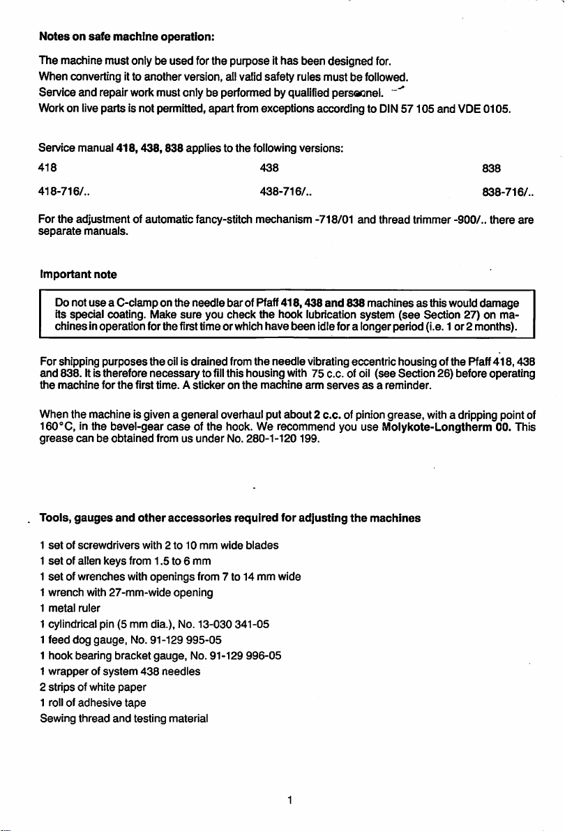
1
Preparations
for
adjusting
Note:
To allow the machine to be blocked with
bearing plate (Fig.1.0.1.)
has
four holes.
the
needle
baratthe
required position
Afterpositioning themeedlebar as requiredpush the pinintothe appropriatehole
it
enters
the
recess
behind the bearing plate, thus blocking the machine.
5mrn
the
until
1.0.1
Page 5
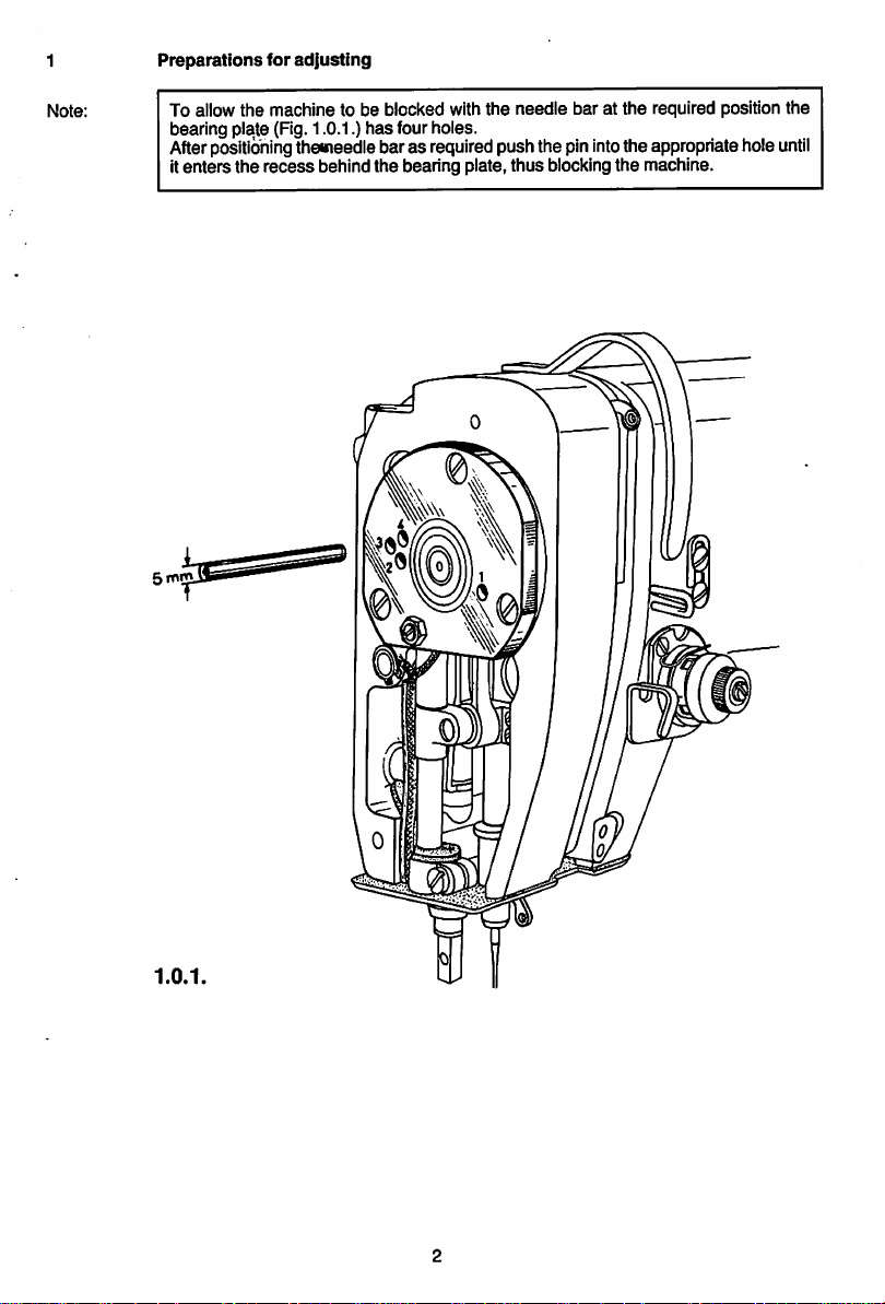
1-1
Take
out
screws
1 from
the
cast
iron
cover
and
needle bar lubricating wickfromits hole inthe coversealing plate.)
remove
.2 Drainthe oilfromthe needle vibratingeccentric housing.
the
cover. (Do not
remove
the
1.0.2
Page 6
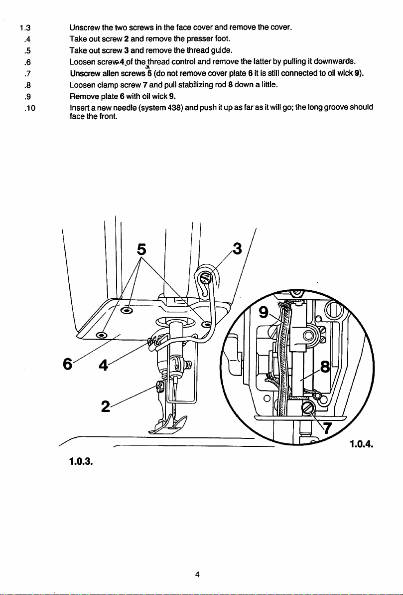
1.3
.4
.5
.6
.7 Unscrew alien screws 5 (do not remove cover plate 6 it is stillconnected to oilwick 9).
.8 Loosen clamp screw7 and pullstabilizing rod 8 down a
.9
.10 Insert a new needle (system 438) and push itup as faras it
Unscrew
Take
out
Take
out
Loosen
Remove
face
the
the
two
screwsinthe
screw2and
screw3and
screv^jof
plate 6 with oilwick 9.
front.
remove the
remove
thejthread
face
cover
presser
the
thread guide.
control
and
and
remove
foot.
remove
the
cover.
the
latterbypullingitdownwards.
little.
will
go; the longgroove should
1.0.3.
1.0.4.
Page 7
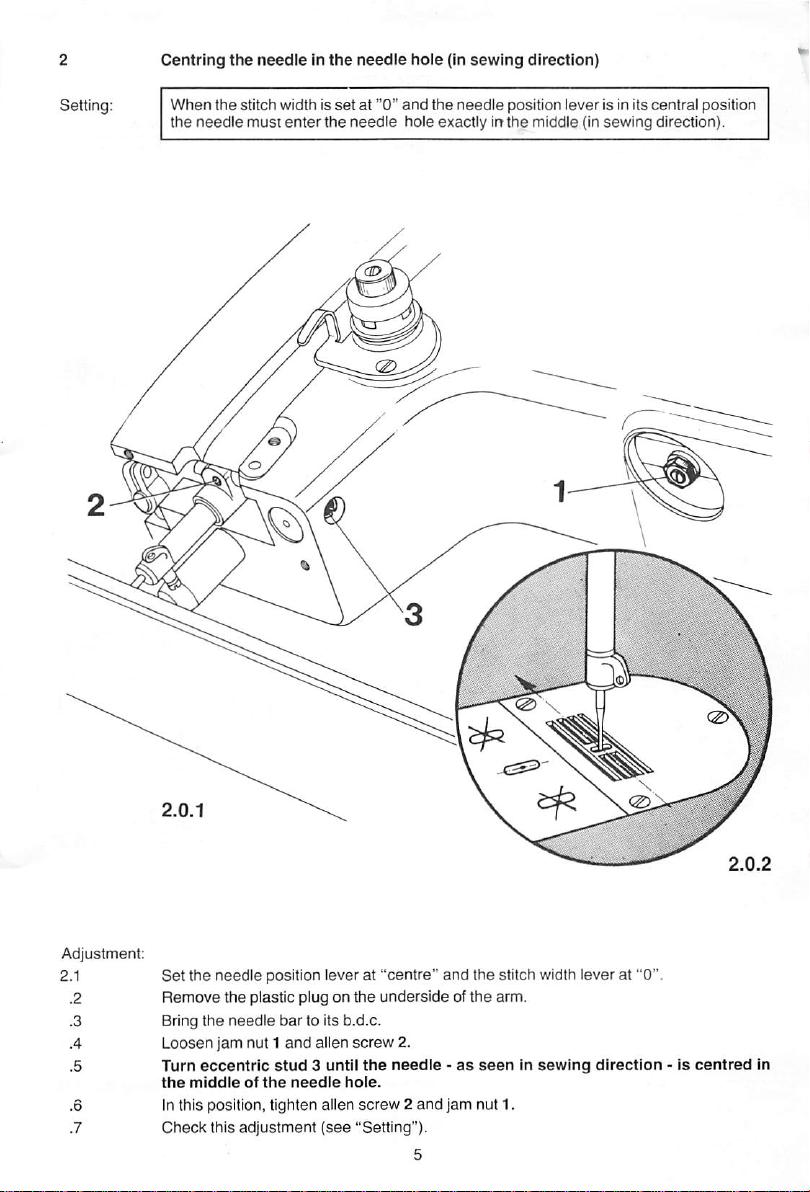
Centring
When
the
needle
the
needleInthe
the
stitch width is
must
enter
the
set
needle
at "0"
needle
hole
and
the
hole
exactlyinthe
(in
needle
sewing
direction)
position lever is in its central position
middle (in
sewing
direction).
1
2
3
4 L(
5
6
7 C
S'
R
B
Ti
th
In
Page 8
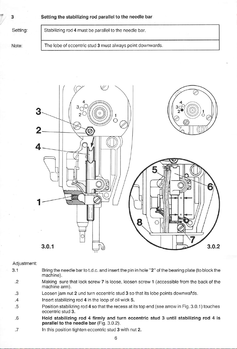
Setting
the
stabilizing
rod
paralleltothe
needle
bar
Setting: Stabilizing rod 4
The
lobe of eccentric
must
be parallel to
stud3must
the
needle
bar.
always point downwards.
Adjustment:
Bring
the
needle
3.1
sure
arm).
bartot.d.c.
that
lock
machine).
lulaking
machine
Loosen
jam nut 2 und turn eccentric
Insert
stabilizing rod 4 in
Position stabilizing rod 4sothat
eccentric
Hold
paralleltothe
In
stabilizing
this
position
stud
3.
rod
needle
tighten
and
screw
7 Is
the
loop of oil wick 5.
4 firmly
bar
(Fig.
eccentric
Insert
loose,
the
and
3.0.2).
stud
recess
the
pin In
loosen
stud3so
at Itstop
turn
eccentric
3 with nut 2.
hole
"2"ofthe
screw1(accessible
bearing
from
plate
the
that Its lobe points downwafds.
end
(see
arrow in Fig. 3.0.1)
stud
3 until
stabilizing
(to block
backofthe
touches
rod
4 Is
the
Page 9
3.8 Tocheck thatitis parailelto the needle bar firstpullstabilizing rod4 downand then push
it up againasfarasit
necessary
•9
Making sure that stabilizing rod 4 is still in contact witheccentric stud 3 tighten clamp
screw
turn eccentric
7 securely.
will
go, making
stud
3 accordingly).
sure
that guide 6
does
not move to the
side
.10 Remove the cylindricalpin from the hole inthe bearing plate.
.11 Bring
.12
the
machine
Screw
on coverplate 8.
needle
arm.
bar
to b.d.c.
and
tighten
screw
1 which is
accessible
from
the
backofthe
(if
Page 10
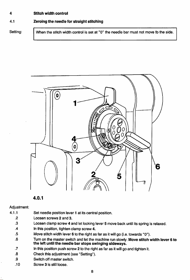
4
4.1
Stitch
Zeroing
width
the
control
needle
for
straight
stitching
Setting:
When
the
stitch
width
controlissetat"0"
the
needle
bar
must
not
movetothe
side.
4.0.1
Adjustment:
4.1.1
.2
.3 Loosen clamp screw 4 and letlockinglever 5 move back
.4 In this position, tighten
.5 Move stitch widthlever 6 to the rightasfarasit
.6 Turnon the masterswitch and let the machine runslowly. Move
.7 Inthis positionpush screw 2 to the rightasfarasit
Set
needle position lever 1 at its central position.
Loosen
the
screws2and
left until
the
3.
needle
clamp
bar
screw
stops
4.
swinging
until
will
go (i.e.towards "0").
sideways.
will
go and tighten it.
itsspring isrelaxed.
stitch
width lever 6 to
.8 Check this adjustment (see "Setting").
.9
.
10
Switch
off
Screw3is
master
still
switch.
loose.
8
Page 11
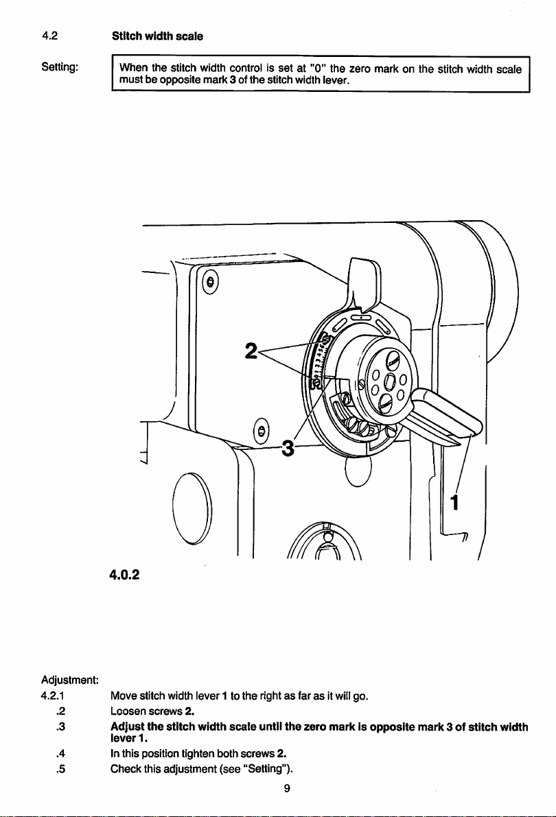
4.2
Stitch
width
scaie
Setting:
When
the
stitch width control is
mustbeopposite
mark
3 of
the
setat"0"
the
stitch width lever.
zero
markonthe
stitch width
scale
4.0.2
Adjustment:
4.2.1
.2
.3
.4
.5
Movestitch
Loosen
Adjust
ieverl.
screws
the
width
lever1 to the rightas faras it
2.
stitch
width
in this position tighten both
Check
this adjustment
(see
scale
screws
"Setting").
untii
will
go.
the
zero
markisopposite
mark
3 of
stitch
2.
9
width
Page 12
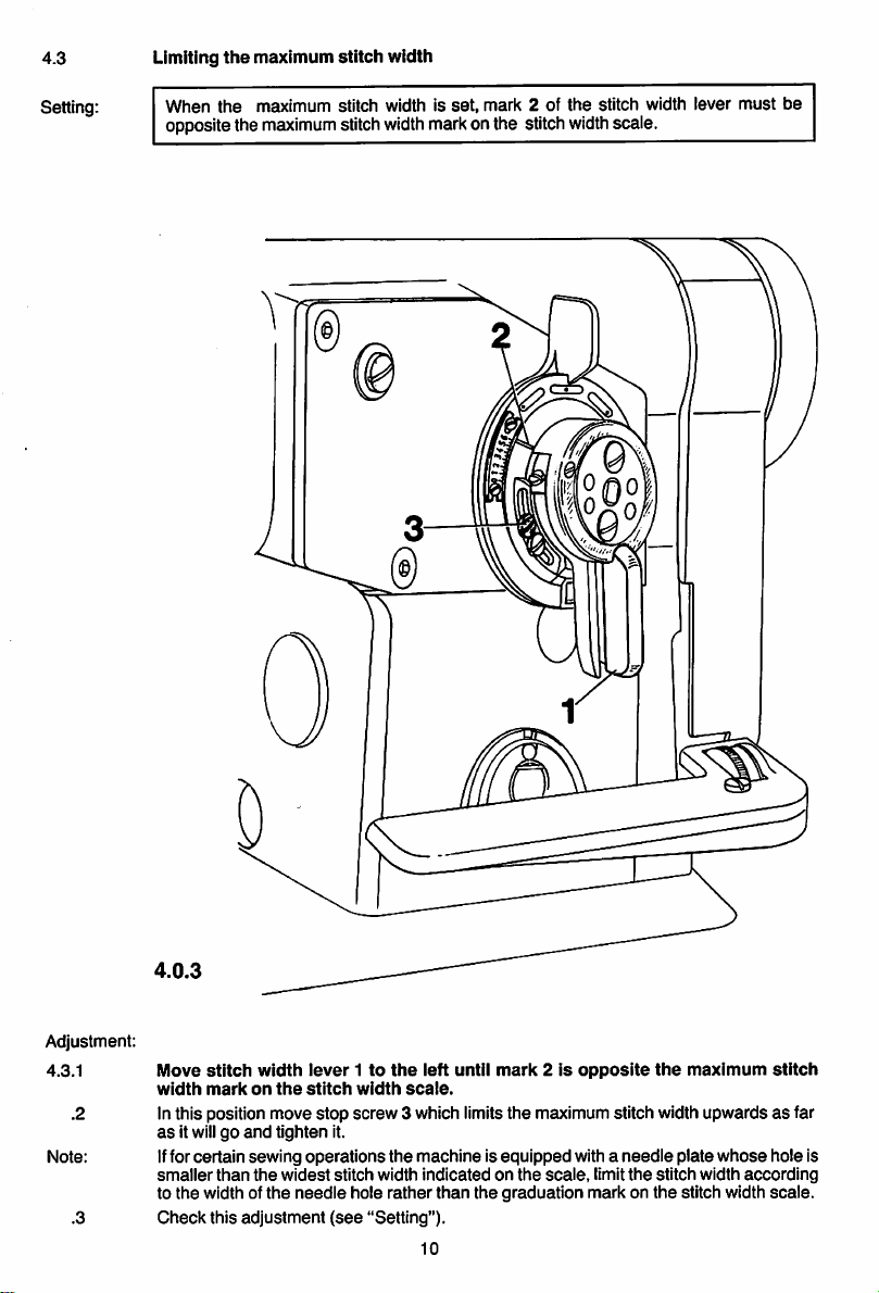
4.3
Setting:
Limiting
When
the
oppositethe
the
maximum
maximum
maximum
stitch
width
stitch width is
stitch
width
set,
mark
2 of
markonthe stitch
the
stitch width lever
width
scale.
must
be
4.0.3
Adjustment:
4.3.1
Note:
Move
stitch
width
width
markonthe
Inthis position move
as
itwillgo
and
tighten it.
lever1to
stitch
stop
the
left
until
width
scale.
screw
3 which limitsthe maximum stitch width upwardsasfar
mark2is
opposite
Iffor certain sewing operationsthe machine is equippedwith a
smaller
than
the
widest
to the width ofthe
Check
this
adjustment
stitch width indicated on
needle
hole rather than the graduation mark on
(see
"Setting").
10
the
scale,
limit
needle
the
the
the
stitch width
maximum
plate
whose
according
stitch width scale.
stitch
hole Is
Page 13
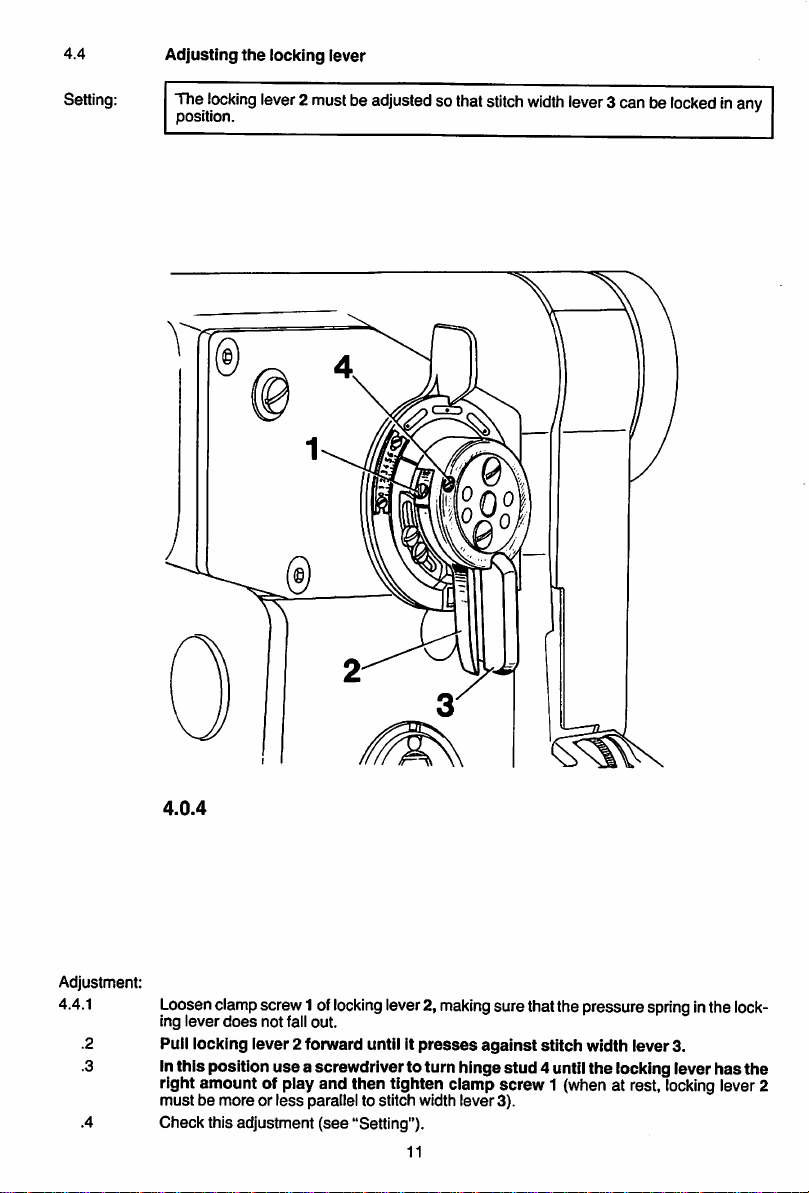
4.4
Setting:
Adjusting
The
locking
position.
the
locking lever
lever2mustbeadjusted
sothat
stitch
width
lever
3can be
locked
inany
4.0.4
Adjustment:
4.4.1
.2
.3
.4
Loosenclampscrew1 of
ing
lever
does
not fall out.
Pull locking lever2 forward until it
In
this
position
locking
lever2,
presses
use
a screwdriverto turn hinge
making
sure thatthe pressurespringinthe
against
stitch width lever3.
stud
4 until
the
locking lever
right amount of play and then tighten clamp screw 1 (when at rest,
mustbemoreorless
Check this adjustment
parallel to stitch width
(see
"Setting").
11
lever
3).
locking
lock
has
lever2
the
Page 14
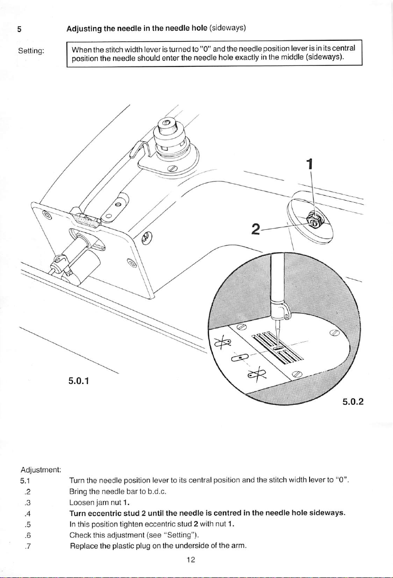
Adjustingthe needle Inthe needle hole
When the stitch widthlever isturned to"0" and the needie position leveris initscentral
position
the
needie
shouid
enter
the
(sideways)
needle
hole
exactlyinthe
middle
(sideways).
m
I
Adjustment:
5.1
Turnthe needie positioniever to its central positionand the stitch widthleverto "0'
Bring the
Loosen
Turn
Inthis position tighten eccentric
Check
Replace
needle
jam
nut 1.
eccentric
this
adjustment
the
plastic plug on the
bar
to b.d.c.
stud2until
(see
the
needleIscentredInthe
stud
2 with nut 1.
"Setting").
undersideofthe
arm.
needle
hole
sideways.
Page 15

6
Adjusting
the
needle
throw
Setting:
Whenthe
in
hole
2) it
needle
must
bar
risesfrom the bottom position on the rightofits throw to t.d.c. (pin
not
movetothe
side
when
the
stitch width
leverismovedtoand
coAmm
fro.
6.0.1
Adjustment:
.1
.2
.3
.4
.5
.6
.7
.8
Loosen screws1 ofzigzag eccentric2 justenough toallow the eccentricto be turned on
its
shaft
against
strong
resistance.
Bring
the
needle
bar
from the bottom position on
the
right of its throw to t.d.c.
Insert cylindrical pin in hole "2" ofthe bearing plate (to blockthe machine).
Moveeccentric 2 sidewayson itsshaft untilthereis a clearance of about 5 mm between it
and
the
rightwall of the casting.
Turn
eccentric2on
width
leverismovedtoand
Check
this
adjustment
Remove
Screws1are
cylindrical pin from hole "2"ofthe bearing plate.
still
its
(see
loose.
shaft
fro.
"Setting").
(See
until
Fig. 8.0.1.).
the
needle
13
bar
stops
vibrating
when
the
stitch
Page 16
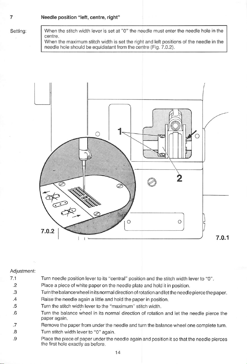
Needle
position
When
the
centre.
When
needle
stitch
the maximum stitch width is
hole should be equidistant from the
"left,
centre,
width
leverissetat"0"
right"
set
the
the
needle
right
centre
must
and
left positions of
(Fig. 7.0.2).
enter
the
needle
the
needleInthe
holeinthe
Turn
needle
position lever to its "central" position
and
the stitch width lever to "0".
Place a piece ofwhite paperon the needle plate and hold itinposition.
Turnthe balance wheel initsnormal direction of rotationand letthe needlepierce the paper.
Raise
the
needle
again
a little
and
Turn
the
stitch
width
levertothe
hold the
"maximum"
paper
stitch
in position.
width.
Turn the balance wheel in its normal direction of rotation and let the needle pierce the
paper
again.
Remove
the
paper
from
under
the
needle
and turn the
balance
wheel
one
complete
Turn stitch width leverto "0" again.
Place the piece of paper under the needle again and position itso that the needle pierces
the first hole exactlyasbefore.
turn.
Page 17

7.10
.11 Move
Making
mum"
and
needle
punctures
that
the
sure
that
the
needle
let
the
vibrating
needle
point is not in
pierce
the
eccentric
paper
2 in
the
again.
the
directionInwhich
mustbemovedinordertoobtainasymmetrical
eccentricisnot
rotatedinthe
process.
.12 Inthis positiontighten screws1 and pushthe circlip
eccentric.
.13 Checkthis adjustment
(see
"Setting").
paper, turn
(see
the
stitch width lever to "maxi
the
two
outer
stitch
pattern;
make
needle
sure
arrow inFig. 7.0.1) up against the
15
Page 18

8
Adjusting
the
needle
position
lever
Setting:
The leftand rightthrows of the needle must be the same both at the widest stitch
setting and at the leftand rightneedle positions.
8.0.1
Adjustment:
8.1
Loosen
screws1and
2.
Tum needle position lever 3 to Its"central" position
mum"
stitch
width.
and
stitch width lever 4to the "maxi
Tum the balance wheel in its normal direction of rotation untilthe descending needle is
positioned
.4
.5
.6
.7
Place a piece ofwhite paperoverthe needle holeand fixitin positionwithadhesive tape.
Turnthe balance wheel Insewing direction untilthe needle pierces the paper.
Turnthe balance wheel inthe oppositedirection and let the needlepierce the paperagain.
Turnstitch widthlever 4 to "0" and push needle position lever 3to the right untilthe point
above
the
left
endofthe
needle
hole.
ofthe needle Ispositioned exactly above the hole last made Inthe paper.
.8
.9
.10
.11
position
In
Push needle position lever 3 to the leftuntilthe point ofthe needle Is positioned exactly
above
the lefthole Inthe paper.
In
this
position
Check this adjustment
push
screw2against
push
screw1against
(see
"Setting").
16
its
stop
and
tighten
it firmly.
its
stop
and
tighten
it firmly.
this
Page 19

9
Adjusting
the
stitch
length
scale
ring
Setting:
When the stitch iength is
graduation
mark
4.
set
at "0" the "0" mark on scale ring 3 must be inline with
Adjustment:
as
9.1
Turn miiied wheel 1
moves
downwards.
.2
.3
Loosen
screw2and
mark
4.
Inthis position tighten
farasit willgoin
turn
scale
ring3so
screw
2.
the
direction in which
that
the
figure
17
the
reverse-feed
"0" is in line with
control
graduation
Page 20

10
Zeroing
the
bottom
feed
Setting:
10.1
When
the
baiance
stitch iength is
wheeiisturned.
Adjustment with
closed
((t
set
at "0"
gearcase.
1/
the
feed
dog
must
not
move
fonward
when
the
10.0.1
Adjustment:
10.1.1
.2
.4
.5
Loosen
clamp
screw
4 of
actuating
Place
a 27-mmwrench on hexagon torsion nut 6
position.
Keep
feed
Hold
against
Check
rotating
dog
the
the
stops
balance
moving
wheel
forward.
wrench in this position and, making
the
casting, tighten
this
adjustment
(see
clamp
"Setting").
crank
and
screw
18
5.
turn
4.
and
the
wrenchonthe
sure
the
thus
hoid actuating shaft 7 firmlyin
torsion
nut
actuating crank 5
and
until
circlip 8
the
are
Page 21

10.2
Adjustment with
open
gearcase.
10.0.2
Adjustment:
10.2.1
.2
.3
Remove the
outofthe
Set
stitch length at
To
makeiteasiertosee
feed
Loosen
resistance.
Turn
driver
rock
the
and
gearcase
gearcase).
shaft
clamp
balance
thus
crank
screw
wheel
the
In this position tighten
Check
this
adjustment
cover on the underside of the machine (collect any oilwhich runs
"0".
when
the
feed
1.
2 just
enough
andatthe
feed
dogiscompletely
clamp
screw
(see
"Setting").
dog is motionless insert a srewdriver in the slot of
to allow
same
time
crank
turn
3 to be
feed
turned
shaft
on its
crank3until
shaft
motionless.
2.
19
the
against
screw
Page 22

11
Adjusting
the
bottom
feed
driving
motion
Setting: When the machine is
beyond
control is
its
t.d.c.
operated.
(pin in hole 4)
set
for its longest stitch
the
feed dog
and
must
the
needle
not move
bar
is positioned 1 mm
when
the
reverse-feed
11.0.1
Adjustment:
11.1 Turn the shaft to
make
screws 1 offeed driving eccentric 2 accessible and loosen them
just enough for the eccentric to be turned againststrong resistance.
.2 Turnthe balance wheel untilthe needle baris positioned 1 mmbeyond itst.d.c.
.3 Insertthe cylindrical pininhole 4 ofthe bearing plate (to blockthe machine).
.4
.5 Move
.6 Inthis position,makingsure that the feed
Set
the machinefor itslongest stitch.
the
the
is
tighten
reverse-feed control up
notchonthe
completely
motionless.
oneofthe
eccentricisvisible
screws
1.
and
and
down
and
the
driving
turn feed driving eccentric 2 until
screwdriverinfeed
rock
eccentric is not moved along the shaft,
shaft
crank
.7 Remove the cylindricalpin from the hole ofthe bearing plate.
.8 Tighten
.9 Checkthis
-10
Remove
the
other
adjustment
the
screwdriver
screw
1.
(see
from
"Setting").
feed
rock
20
shaft
crank
3.
3
Page 23

12
Bottom
feed
lifting
motion
12.1
Setting;
On
Cl.
418
and
438
When thestitch length is
t.d.c.
(pin in hole 4)
set
at "0" and the needlebar is positioned1.0 mm
the
feed
dog
must
be at its
td.c.
beyond
its
12.0.1
Adjustment:
Set
the
12.1.1
.2 Loosen
.3 Turn
.4 Insert
.5 Tomake iteasierto recognise the
.6
.7 Inthis position, making
stitch length at "0".
screws
the
balance
the
cylindricalpin in hole "4" ofthe bearing plate (to block
crank
3.
Turn
feed
lifting
crank3isatits
tighten
the
accessible
1 infeed liftingeccentric 2.
wheel until
eccentric2on
b.d.c.
the
needle
dead
Its
(see
arrow in Rg. 12.0.1.).
sure
that feed
screw
1.
bar
centre positioninserta screwdriverintheslotof
shaft
lifting
is positioned
until
the
screwdriverInfeed
eccentric 2
1.0mmbeyond
the
does
not move along the shaft,
its
machine).
.8 Remove the cylindrical pinfrom the hole ofthe bearing plate.
.9 Tighten
.10
Check
the
this
adjustment
second
screw
(see
1.
"Setting").
21
t.d.c.
lifting
lifting
shaft
Page 24

12.2
OnCI.838
Setting: Whenthe stitchlengthis set at "0" and the needle bar is positioned1.0 mm
t.d.c.
(pin in hole 4)
the
feed dog
must
be at its t.d.c.
beyond
Its
12.0.2
Adjustment:
12.2.1
.2
.3 Turnthe balance wheel untilthe needle par is positioned 1.0 mm
Set
the stitch length at "0".
Loosen
screws
1 in
feed
lifting
eccentric
2.
beyond
its Ld.c.
.4 Insert the cylindricalpin in hole "4" ofthe bearing plate (to block the machine).
.5 Turn
.6 Inthis position, tighten
.7 Remove
.8
Tighten
feed
lifting
eccentric2on
the
the
cylindricalpin from the hole ofthe bearing plate.
the
second
screw
its
accessible
1.
shaft
screw
until
the
feed
dog
is at
its
Ld.c.
1.
.9 Check this adjustment (see"Setting").
22
Page 25

13
Tensioning
the
driving
beltinthe
gearcase
Setting:
The driving beit must be tensioned so that the
machine
does
not
bind.
gears
have no backlash, but the
o
O
13.0.1
Adjustment:
Loosen
screw
sure
the
not
this
1.
driving
that
eccentric
bind.
adjustment
gear
3.
eccentric
bushingsothat
screw
1.
(see"Setting").
bushing
23
2 is not moved,
the
gears
have no
the
tension
backiash
middie of
the
driving beit by
but
the
13.1
.2
Move eccentric bushing 2 until the driving belt is positioned in
case
opener
Making
turning
does
Inthis position tighten
Check
the
bobbin
machine
Page 26

14
Setting:
Adjusting
The
hook
bearing
the
hook
shaft
bracket
bearing
must
gauge.
contact
bracket
both
the
vertical
and
horlzontai
surfacesofthe
14.0.1
hook
14.0.2
Adjustment:
14.1
.2
.3
.4
.5
Remove bed slide, needle plate, feed dog and bobbin
Loosen clamp screw 1
Loosen,the two hook
and
swing the bobbin
set
screws and remove the sewing hook fromits shaft.
case
case
opener
position finger.
to the right.
Loosen alien screw 2 on the bedplate and releasethe taper keyofhook bearing bracket 3
underneath this screw bytapping the head ofthe alienscrew
Screwonthe
hook bearing bracket
gaugesothat on Ci.
438
lightly
witha hammer.
and
838
machines
438-439and onCi.418 machinesnumber418-419can be read fromthe front(Fig.14.0.1).
By
turning
with both
In this position tighten alien
Unscrew
and
moving
the
vertical
and
remove the hook bearing bracketgauge.
hook
and
bearing
horizontal
screw
2.
24
bracket3bring
surfacesofthe
the
hook
shaft
into
hook bearing bracket gauge.
number
contact
Page 27

15
Preliminary
adjustmentofneedle
bar
height
Setting:
When
between
the
needle
needle point
bar
is at t.d.c. (pin in hole "2")
and
needle
plate.
there
mustbeclearance
of 19
mm
15.0.1
Adjustment:
Bring
15.1
the needle bar to
Place
the
.2
.3
.4
Loosen
Adjust
19 mm
.5
.6
Inthis position tighten
Remove
needle
screws
the
needle
between
the
needle
t.d.'c.
plate in the
1 in
the
needle
bar
.vertically - without
needle
point
screws
plate again.
and insertthe cylindrical pinin hole "2" ofthe bearing plate.
needle
plate cutout.
bar
and
1.
connecting
needle
25
stud.
turning
plate.
it - untii
there
is a
clearance
15.0.2
of
Page 28

16 Oil
distributor
ring
Setting: When the hook is incontact with the oildistributor ring there must be a clearanceof
0.2-0.3 mm
between
the hook point
and
the middle of the
clearance
cut of the
needle
(Fig. 16.0.2).
16.0.1
Adjustment:
16.1
.2
.3
.4
.5
.6
.7
Set the stitch
Place
width
leverat "0" and the needle positionlever at itscentral position.
the sewing hook on the hook shaft.
Bringthe needlebar toa position2 mm beyond b.d.c. but make sure the needle
strike
the
sewing hook.
Loosen
screw
1 of oil distributor ring 2.
Making
sure
that
the
butor
ring
and
the
hook
point and the middle of the clearance cut of the needle
hook is up
In this position tighten
Check this adjustment
screw
(see
until
thereisa
1.
"Setting").
against
the
oil distributor ring, movethe oil distri
clearanceof0.2-0.3mmbetween
26
(Fig.
16.0.2).
does
the
16.0.2
not
hook
Page 29

17
Hook
timing,
hook-to
needie
ciearance
and
bobbin
case
position
finger
Setting:
Withthe
needle
needle
position lever InItscentral position, the stitch width lever at "0"
bar
at a position 2 mm beyond b.d.c. (pin In hole "1") the hook point
and
the
must
be exactly oppositethe centre lineofthe needle. Also,Inthisposition, there should bea
clearanceofabt.
0.1mmbetween
hook
point
and
needle.
17.0.1
Adjustment:
17.1
.2
.3
.4.
.5
.6
.7
.8
Bring
the needle bar to a position 2.0 mm beyond b.d.c., makingsure that the needle
does
not strike the sewing hook. Blockthe machineInthis position byinserting the pin In
hole
"1" of
the
bearing plate.
Set
the stitch width lever at "0" and the needle position lever at Itscentral position.
Turnthe sewinghook on Itsshaft
until
Itspoint Isopposite the centre line ofthe needle.
Adjustthe hookiateraiiy,howeverwithoutturning it, untiithere isa ciearanceof 0.1
mm
between
Inthis position, tighten the accessible hook
Screwonthe
bobbin
the
bobbin
Pull
the pinoutofthe holeInthe bearingplateand tightenthe second hookset screw1.
Check this adjustment
case
its
bobbin
base
case
point
and
base.
and
the
needie.
case
position fingersothat
that
(see
thereisa
"Setting").
clearanceof0.5mmbetween
27
set
screw 1.
it is positioned in
its
the
front
slotofthe
edge
and
Page 30

18
Final
adjustmentofneedle
bar
height
Setting;
Withthe stitch width lever at "0", the needle position lever at its left position and the
hook point positioned exactlyopposite the needle, the bottom
must
be positioned 0.5 mm
above
the
top of the
needle
eye.
edge
ofthe hook point
18.0.1
Adjustment:
18.1
.2
.3
.4
Set the stitch widthlever at "0" and the needle positionlever to itsleftposition.
Turn the balance wheel untilthe hook point is exactly opposite the needle.
Loosen bothclamp screws 1 of the needle bar connecting stud.
Push
the
needle
bar
up or
down
until
the
hook
pointis
topofthe
needle
eye.
Inthis position, tighten bothscrews1, making
28
sure
positioned
that the needlebar
0.5 mm
has
not
18.0.2
above
been
V
the
tumed.
Page 31

19
19.1
Bobbin
case
opener
Positionofbobbin
(not on 838)
case
opener
Setting:
There
must be a
bobbin
case
between
case
base
between
the bobbin
clearance
base
(Fig.19.0.3). Furthermore,
the
top of
(Fig.19.0.2). And, finally,
the right
side
case
opener
19.0.2
of abt. 0.8 mm
the
bobbin
ofthe bobbin
is at its left point of reversal (Fig.19.0.4).
R
case
position finger
case
there
slot
between
there
must
should
and
the bobbin
bobbin
be a
and
the
be a
clearanceofabt.
case
case
opener
clearanceofabt.
inner
edgeofthe
position finger
finger
0.5
0.3
and
mm
bobbin
mm
when
19.0.3
19.0.4
Adjustment:
19.1.1
Turn bobbin
.2
Push
screw
tance.
Loosen alien
case
opener
finger 1sothatitcontacts
the
opener
finger against clamp crank 2 located underneath and tighten clamp
3 just sufficiently to allow
screw
4 of the eccentric bobbin
the
the
opener
finger to be turned on Its shaft
case
opener
29
right
bushing.
sideofthe
bobbin
against
19.0.1
case
slot.
resis
Page 32

19.1.4 Turn
the
the
eccentric
bobbin
of
(Fig. 19.0.2).
.5
Adjust
the
bushinginheight
0.8mmbetween
(Fig. 19.0.3).
.6 Inthis position, tighten alien
.7 Turn the
.8
.9 Inthis position tighten
Turn
base,
case
clamp
balance
the
opener
until
thereisa
slot
and
the
crank2underneath.
.10 Check this adjustment
o
bushing
case
opener
until
thereisclearanceofabt.
finger
without
bobbin
case
opener
screw
4.
wheel to bring the bobbin
fingeronits
clearanceofabt.
bobbin
clamp
(see
19.0.2
shaft,
case
position
screw
"Setting").
3, making
and
the
inner
turning
finger
and
case
opener
making
sure
0.3mmbetween
finger
(Fig. 19.0.4).
sure
0.5 mm
edgeofthe
it until
there
the
is a
edgeofthe
to its leftpoint ofreversal.
it still
contacts
the
right
the
bobbin
case
between
bobbin
the
case
clearanceofabt.
bobbin
case
the
bobbin
sideofthe
opener
still
bobbin
contacts
top
base
base
case
19.0.3
19.0.4
30
19.0.1
Page 33

19.2
Timing
the
bobbin
case
opener
Setting:
When the needlebar is at a position2.0 mm
beyond
finger must be at its right pointof reversal(Fig. 19.0.6).
b.d.c. (pininhole "1") the opener
€)
19.0.6
Adjustment:
Loosen
the
three
screws
19.2.1
1 of bobbin
.2
.3
.4
Tighten the central
against
resistance.
Bring
the
pin in
needle
hole
screw
bar
"1" (to block
1 just sufficiently to allow eccentric 2 to be turned on its shaft
to a position
the
To facilitate determining the
slot of
the
clampofopener
Turn
opener
eccentric
2 until
machine).
finger 3.
case
opener
eccentric
2.0mmbeyond
exact
point of reversal insert a small screwdriver in the
opener
finger
3 isatits
b.d.c.
2.
and,
in this position,
right
pointofreversai
(Fig. 19.0.6).
Pull
the
pin out of
Tighten the central
Pull
the
screwdriverout of
ment
(see
the
"Setting").
holeinthe
screw
bearing
1 first, thenthe two outer
the
clamp
31
slot of
plate.
the
bobbin
screws
case
1.
opener
and
check
this
O
19.0.5
insert
adjust
1—
the
Page 34

20
Adjusting
the
slack
thread
control
Setting:
When the needle bar is at b.d.c. the bottom
be inline with
20.0.2
the
top
edgeofthe
hole in
edge
the
ofthe slack thread control wire must
threadguide(Rg. 20.0.2).
Adjustment:
20.1
.2
.3
Push
slack
thread
control wire 1 on
the
needle
position of
top
edgeonthe
bar
Bring
Adjust
the
with
the
the
bedplate.
Inthis position tighten
Check this adjustment
to b.d.c.
slack
screw
(see
bushing2and
thread
holeinthe
3.
"Setting").
control
thread
32
hold it inposition.
wire 1sothat
guide,
and
make
its
bottom
sureitis
edge
set
Is In line
parallel
20.0.1
to
Page 35

21
Clearance
between
presser
foot
and
needle
plate
Setting:
When the
presser
presser
foot
21.0.1
bar lifter is raised there must be a clearance of 7 mm between
and
needle
plate.
Adjustment:
21.1
Screw on feed dog, needle plate and bed slide.
Making
sure
central position, raise the
that the stitch width lever is at "0" and the needle position lever is in its
presser
bar
lifter.
Replace the presser foot and lower it onto the needle plate by means of the presser
bar
lifter.
.4
Reduce the pressureofthe presser bar by turning out regulatingscrew 1 untilthe presser
foot is pressed againstthe needle plate onlyslightly.
.5
.6
.7
.8
.9
.10
Push the 7-mm-thick part of the
under
the
hinge of the
presser
Loosen clamp screw 2 of the
Tum
the
balance
wheel
Adjust
the
holeofthe
in
this
position
screw
2.
Check
this
position of
presser
adjustment
push
the
foot.
the
(see
lifting
until
the
presser
lifting
"Setting").
gauge
under the presser foot from behind so that it is
foot.
bracket and raise the presserbar
needleisdowninthe
footsothat
bracket
downasfarasit willgoand
33
the
needle
needle is
lifter.
holeofthe
centred
presser
exactly in
tighten
foot.
the
clamp
Page 36

22
22.1
Feed
On
Ci.
dog
418
height
and
438
Setting:
Withthe stitch
hole"4") the
entire
length (Fig. 22.0.3).
set
at "0" and the needle bar at a position 1.0 mm
feed
dog
mustbecentred
Inits slots
and
contactthe
beyond
gauge
td.c.
(pinin
throughoutIts
22.0.2
Adjustment:
22.1.1
Bringthe needle bar to a position.1.0 mm
the
bearing plate (to block
.2
.3
.4
.5
.6
clamp
the
screws1and
gauge
under
the
Loosen
Place
edge
is flush with
Lowerthe presserbar lifterto rest the
Push the feed bar upwards, centre the feed dog inthe needleplate slots and holditin this
position.
Tumfeed
lifting
crank 3
the
machine).
2.
the
presser
edgeofthe
until
needle
the feed dog contacts the gauge and tighten
beyond
footsothat its
plate.
presser
foot on the gauge.
t.d.c. and insertthe pinInhole "4"of
recess
faces
downwards
and
damp
just lightly.
.7
.8
Turn
tact
eccentric
with
bushing5underfeed
the
gauge
throughout Its entirelength and tightenclampscrew 2 lightlytoo.
rock
shaft
crank
4 until
the
feed
dog
Is in
Tightenclampscrews 1and 2,makingsure the feed dog iststillin contactwiththe gauge
throughout its entire length.
.9
.10
Raise the presserfoot
out of
the
hole in
lifter,
the
bearing plate.
removethe gaugefromunder the presserfootand pullthe pin
Check this adjustment (see "Setting").
34
22.0.1
Itsfront
screw 1
con
Page 37

22.2
On
Cl.
838
Setting:
With
the
hole "4")
stitch
the
teethofthe
set
at "0"
and
the
needle bar at a position 1.0 mm
feed
dog
must
be 1mmabove
the
beyond
needle
plate.
td.c.
(pinin
Adjustment:
22.2.1
Bring
the needle bar to a position1.0 mm beyond
td.c.
and insertthe pininhole "4" of
the bearing plate (toblockthe machine).
.2
.3
.4
.5 In
Loosen
Lift
presser
Turn
eccentric
this
position, tighten
screw
1.
foot by
2 until
means
the
screw
ofthe
lifting
teethofthe
1.
lever.
feed
dog
are
1 mm
above
the
needle
.6 Take the pinout of the hole inthe bearing plate.
.7 Check this adjustment
(see
"Setting").
35
plate.
Page 38

23
Oil
check
valve
Setting:
Note:
There should be a
clearanceof1.0mmbetween
actuating rod 2 of the centrifugal
governor and push rod3 ofthe oilcheck valve (Fig.23.0.2).
If
the
machine
case
with abt. 130 c.c. of Pfaff
has
been
in operation for a longer time, it is
sewing
machine
recommendedtofill
oil No.
280-1-120144
the
having a
gear-
mean
viscosityof22.0 mm^/sat 40°Cand adensityof0.865 g/cm^at 15°Cbeforethe gearcase
cover
is closed.
91-168384-05,
The
two oil
shouldbereplaced
pads,
1
which
too.
are
available
under
Nos.
91-168383-05
and
p
b
23.0.2
Adjustment:
23.1
.2
.3
.4
.5
.6
.7
.8
.9
Loosen
screw1of
Push
actuating
Press
push
Reposition
rod2and
In this position tighten
Place
the
its
Clean
Replace
Check
oil
smallest
the
the
this
rod 2 to
rod 3 into oil
oil
check
push
rod
padinthe
cutout.
gasket
face on the
gearcase
adjustment
the
oil
check
valve.
the
leftasfarasitwill
check
valve 4 until a
valve
4 until
3 (Fig. 23.0.2).
screw
1.
gearcasesothat
gearcase
cover
and
tighten
(see
"Setting").
there
36
go.
resistance
Is a
clearanceof1.0mmbetween
the
vertical fin in
and
the
gasket
screws
of the
crosswise.
is felt.
the
gearcase
gearcase
actuating
is positioned in
cover.
23.0.1
Page 39

24
Tension
release
mechanism
(Thisadjustment procedure
trimmer.)
does
not
applyto machines equipped withsubcl. -900 thread
Setting-
When the presser bar lifteris raised both tension discs should be at least0.5 mm apart
(Fig. 24.0.2).
Q)
24.0.1
Adjustment:
24.1 Take out
.2 Lowerthe presser footontothe needle plate bymeans ofthe presser bar
.3 Loosenclampscrew 1 of
itwillgo.
.4 Bring
the
the
needle
four
screws
bartob.d.c.
of the arm
lifting
rear
cover
and
swing the
cover
out to
levercrank2 and pushtheconnecting roddownas faras
the
lifter.
.5 Raise the presserfoot and placethe feed dog gauge under the foot withits recess up.
.6 Lowerthe presser foot intothe recessof the gauge.
.7
Loosen
screw
3 of
tension
release
cam
37
4.
24.0.2
right.
Page 40

24.8
.10
.11
.12
.13
.14
.15
Adjust
tension
release
cam
4 on Its
tension
.9
Swing up
In
tighten
this
release
the
presser
position,
screw
3.
pin
push
5.
bar
tension
lifter until a
release
resistance
cam
shaftsothat
is feit.
4 up
it is
positioned
against
tension
exactly
release
opposite
pin 5
and
Remove the feed dog gauge from under the presser foot and lowerthe presser foot onto
the
needle
plate again.
Tightenclampscrew 1, makingsure thatretainingring6onthe
lifting
shaft isstiilincontact
withthe face side of the machine and crank 2 contactsthe casting.
Check this adjustment
Screwonthe
The
arm
face
rear
cover remains swung out.
cover.
(see
"Setting").
0
24.0.1
38
24.0.2
Page 41

25 Lubrication of
zigzag
eccentric
25.1
Note:
Fill
the zigzag eccentric housing with abt. 75 c.c. of oil.
Only
and a densityof 0.865
25.2 Clean the
.3
cover.
Screw
on the cover, making
the
hole of
use
Pfaff
sewing machineoil
gW
gasket
face on the coverof the zigzag eccentric housing and the
the
sealer
sure
plate.
having
a mean
viscosity
at 15°C(No.280-1-120144).
that the
needle
bar lubricating wickis stillpositioned in
of 22.0
mm^/s
gasket
at 40°C
ofthis
39
Page 42

26
Hook
lubrication
Setting:
Afterthe machine
appear
on a piece of
has
paper
i
run at full
placed
[m
speed
overthe
for
about
ten
seconds,
a fine trace of oilshould
needleplate cutout abovethe hookraceway.
0
26.0.1
Adjustment:
26.1
.2
.3
.4
.5
.6
Checkthe
22.0
upper
Tuminregulatingscrew1 oftheoilcheckvalveas faras it
a
turn.
Switchonthe
oil
level
mm®/sat40°C
mark. We recommend Pfaff sewing machine oil No. 280-1-120144.
machine
anda
and
density
runitfor
of0.865
about
and,ifnecessary,topupthe
reservoir
g/cm^at15°C
one
minute.
with
oil
with
until
the
oil
level
will
go,and then backabout half
a mean
isin
Remove needle plate and feed dog and take the needle out of the needle bar.
Placea piece ofwhite paperover the needle plate cutout and holditthere.
Letthe machine runabout ten seconds. Thencheck to
see
ifa finetrace ofoilhas appear
viscosity
line
ed onthe paper opposite the hook raceway.
.7
.8
.9
.10
If
too
much
turnitout
oil is emitted,
somewhat.
turn
regulating
screw
Check thisadjustment (see "Setting").
Replace and screwon feed dog and needle plate.
Replace
the
needleinthe
needle
bar.
40
line
littie;orif
too
little oil Is
with
the
emitted
of
Page 43

27
Setting:
Knee
When
plate
lever
the
knee
by a little
stroke
more
limitation
lever is fully
than
7.0mmand
((
operated,
the
the
presser
presser
foot mustbe lifted from the
bar
lifter
must
drop
by its
own
needle
weight.
27.0.1
Adjustment:
27.1
.2
.3
.4
Placethe feed dog
Lowerthe
Loosen
Move
presser
Hold
back
Remove the feed dog
Check
presser
locknut 1
the
knee
foot
must
the
knee
outbyone
this
adjustment
and
levertothe
leveratthis
turn,
gauge
under the
presser
footso that Its
foot onto the feed dog gauge.
turn
stop
screw2out
notbelifted off
right
position
and
lock It In
gauge
from
(see
"Setting").
under
until a
the
and
place
41
a few turns.
noticeable
gauge.
turn
with locknut 1.
the
presser
stop
recess
resistance
screw
2 Inasfarasit will
foot.
faces the needleplate.
Is felt;
however
go,
J
the
then
Page 44

28
Knee
lever
play
Setting:
There
mustbea noticeable
when
the
knee
A
db
0
leveris
f
amount
operated
of play
just lightly.
between
0
nut 2
and
forked connection 3
28.0.1
Adjustment:
28.1
.2
.3
.4
Loosen
locknut1of
Turn in
nut
nection3when
Lock nut 2 in place by tightening locknut 1.
Check this adjustment
2 until
the
nut
there
knee
2.
is a
(see
noticeable
lever is
"Setting").
operated
42
amount
just
of play
lightly.
betweenitand
forked
con
Page 45

Bobbin
winder
When
the
bobbin winder is
the bobbin winder is
wheel
2.
The
bobbin winder
has
reached
a point abt. 1 mm below its rim (Fig. 29.0.2).
engaged,
disengaged,
must
stop
the
winderspindle must be driven reliably;
however, friction wheel 3
automatically
when
the
thread
must
not
wound on
contact
the
when
drive
bobbin
Raise
the
presser
bar
lifterand
Loosen
both
screws
1 in
Set
drive
driven
wheel2so
reliably
when
be driven by drivewheel 2
Tighten
both
screws
1.
Place a bobbinon the winder spindle, thread the machine for bobbin winding,
bobbin
winder
and
start
Loosen
screw
4 of
stop
If
the
bobbinistoo
full
enough,
After
the
adjustment,
If
the
thread
accordingly.
Check
this
adjustment
full,
pushittoward
tighten
piles upon
Finally, replace the arm
engage
drive
wheel
2.
closetofriction
the
bobbin
winderisengaged,
when
the
the
machine.
latch 5.
push
regulating
the
left.
screw
4.
one
sideofthe
{see
"Setting").
rear
cover
with
the bobbin winder.
wheel3that
bobbin
winderisdisengaged.
stud6toward
bobbin, adjust the
the
four
screws
the
bobbin
but
thread
winder
that
friction wheel 3 will
the
right, if
guide
spindle
the
bobbinIsnot
on the
engage
machine
29.0.2
will
be
not
the
arm
Page 46

30
Thread
check
spring
and
thread
regulator
Setting:
Note:
The
stroke of the thread
needie
reaches
the
check
materiai (abt. 7.0 mm stroke).
spring must be completed when the point of
the
Special sewing operations may make Itnecessary to choosea longer or shorter stroke.
30.0.2
30.0.1
Adjustment:
30.1
Loosen both screws 1 ofthread tension piate 2 just sufficiently to allowthe tension barrel
to be turned inthis plate.
Turn tension barrel 3 until the stroke of the thread checkspring amountsto abt.
7.0
mm
inthis position,tighten bothscrews 1 ofthread tension plate 2 evenly.
Check this adjustment
(see
"Setting").
Loosen both screws4 of thread regulator 5.
Push
the
thread
regulatorupas
Inthis
position,
tightenbothscrews 4. (The
on the type of thread and
pearanceofthe.seam).
Screw
on thread guide 6.
31
Presser
foot
pressure
31.1 Threadthe machine,place a piece of
foot
onto
it.
material
farasIt will
go.
position
ofthethread regulator isdependent
used and should be adjusted
fabric
underthe presser footand
according
lower
the presser
.2 Turninregulatingscrew 1 (Fig.21.0.1) untilproper feedingofthe materiai isensuredeven
at
top
speed.
44
to the ap
Page 47

Annex
32
for
machines
Needle
equipped
vibration
with
zigzag
control
-716/..
Setting:
The
sideways
motion of the
terial. (Check with
the
needle
machine
bar
should
set
at its widest zigzag stitch.)
cease
when the
needle
enters
the ma
32.0.1
Adjustment:
32.1
Unscrew
pullthe needle
.2
.3
.4
Set
Loosen
Turn
when
Inthis position,tighten the two
ner
Check this adjustment
the
stitch width
the
needle
the
wall
and
the
two
needle
cast-iron
vibration
needle
coverofthe
bar
lubricating wick out of its hole in the cover sealing plate.
leveratthe
screws
1 of
cam3so
enters
the
vibrating
(see
needle
widest
gear
2.
that
material.
gear
cam3the
"Setting").
vibrating
zigzag
the
needle
set
screws 1, making sure
stitch.
bar
cam
has
right inner wallsothat they
45
housing, making
completed
sure
Its
sideways
gear
2 contactsthe leftin
havenoend
you do not
motion
play.
Page 48

33
Left,
center
and
right
needle
positions
Setting:
With the machine
set
at its widest zigzag stitch, the right and left needle punctures
should be equidistant from the central needle puncture (Fig. 33.0.2).
33.0.1
Adjustment:
33.1
.2
.3
Movestitchwidthlever 1 (Fig.33.0.1) to the widestzigzag stitch.
Place a piece ofwhite paper on the needle plate and holdit there.
Tum
the
balance
wheel
in its normal direction of rotation
and
let
the
needle
stitches of a complete pattern.
.4
.5
.6
Hold
the paper fast and tumthe balancewheel
positioned a little
Set
needle
Tumthe balancewheelInits
above
the paper.
position lever 2 at "center" and stitch width lever 1 at "0".
normal
until
the
point
directionofrotation
ofthe ascendingneedleis
until
the needle
point
pierces the paper. This needle puncture should be centered between the two outer
punctures
If
itis
(Fig. 33.0.2)
not,
takeoutthe
four
alien
screws3ofthe
stitch
width
regulator
plate
(Fig.
and remove the plate by pullingitforward.
46
stitch all
again
33.0.1)
Page 49

33.8 Loosen lockout 4 (Fig. 33.0.3).
.9 Replace the stitch width regulator plate and
.10 Loosen
.11 Turn eccentric bushing 6
.12
screw
"Setting" is
Tighten
screw
5 (Fig. 33.0.4).
obtained.
5.
uritii
a symmetrical stitch patternasdescribed
.13 Again unscrew the stitch width regulator plate.
.14 Tighten lockout 4 while retaining
.15 Clean
the
stitch width regulatorplate
screw
and
apply sealing compound and screw the plate down.
.16
Check
this adjustment
(see
"Setting").
secure
itin position with two
5 witha screwdriver.
the
surface
contactingthe machine arm casting,
screws
under
only.
33.0.4
33.0.3
47
Page 50

34
34.1
Needle
Fixing
position
the
left
lever
needle
position
Setting:
The
straight-stitch punctures in the left
needle puncture
made
at maximum stitch width.
needle
position should coincide with
the
left
Adjustment:
34.1.1
.1.2
.1.3
.1.4
.1.5
Loosen needle position
Set needle
Turn
left of
the
its
position
balance
throw
andatbottom
limiting
screws 1 and 2.
lever3 at"center"and stitch
wheel
in its normal direction of rotation until
dead
center.
width
lever4 atthewidestzigzagstitch.
the
needle
is at
the
Moveneedle position lever 3 graduallytoward the leftwhileconstantly actuating stitch
width lever 4 untilthe needle
Inthisposition, push stopscrew1 upas faras it
screw2loose
however.
does
not move any more.
48
will
go andtightenitsecurely.Leavestop
34.0.1
extreme
Page 51

34.2 Fixingthe right needle
potion
Setting:
The straight-stitch puncture in the right needle position should coincide with the
right
needle
puncture
made
at maximum stitch width.
34.2.1 Set needle positionlever3 at"center" and stitchwidthlever 4 at the widestzigzag stitch.
.2
Turn
extreme
the
balance
rightofIts
wheelInIts
throw
andatbottom
normal
directionofrotation
dead
center.
until
the
needleisat
the
.3 Move needle position lever 3 gradually toward the right whileconstantly actuating stitch
width lever 4 untilthe needle doe's not move any more.
.4 Inthis position,
.5
Check
this adjustment
push
stop
(see
screw
"Setting").
2 to
the
leftasfarasit willgoand
tighten itsecurely.
49
Page 52

r
PFAFF
Sr-
%
^ .
Pfaff,
D-6750
'-i:
296-!2-i26i.i
Innovation
Koisersioutern. Postfoch
modebyPFAFF
3020/3040.
Telefox (0631) 17202
Telefon (0631)
2000.
Telex
45753
 Loading...