

Page 1

296-12-18 413/002
Betriebsanleitung engl. 12.94
Instruction manual
3827-2/24
This instruction manual applies to machines from the
following serial numbers onwards:
# 1484416
Page 2

The reprinting, copying or translation of PFAFF Instruction Manuals, whether in whole or in
part, is only permitted with our previous permission and with written reference to the
source.
G.M. PFAFF KAISERSLAUTERN
INDUSTRIEMASCHINEN AG
Postfach 3020
D-67653 Kaiserslautern
Königstr. 154
D-67655 Kaiserslautern
Editing / Illustrations
HAAS-Publikationen GmbH
D-53840 Troisdorf
Page 3

Contents
Contents..................................................................................... Chapter - Page
1 Safety ........................................................................................................ 1 - 1
1.01 Directives ................................................................................................... 1 - 1
1.02 General notes on safety ............................................................................. 1 - 1
1.03 Safety symbols...........................................................................................1 - 2
1.04 Important points for the user ..................................................................... 1 - 3
1.05 Operating and specialist personnel ............................................................ 1 - 3
1.05.01 Operating personnel................................................................................... 1 - 3
1.05.02 Specialist personnel 1 ................................................................................ 1 - 4
1.06 Danger .......................................................................................................1 - 4
2 Proper use.................................................................................................2 - 1
3 Specifications ........................................................................................... 3 - 1
4 Disposal of the machine .......................................................................... 4 - 1
5 Notes on testing in accordance with EN 60204-1 ..................................5 - 1
6 Transport, packaging and storage .......................................................... 6 - 1
6.01 Transport to the customer’s premises ....................................................... 6 - 1
6.02 Transport within the customer’s premises ................................................6 - 1
6.03 Disposal of the packaging .......................................................................... 6 - 1
6.04 Storage....................................................................................................... 6 - 1
7 Explanation of the symbols..................................................................... 7 - 1
8 Operational controls and optical displays..............................................8 - 1
8.01 On/Off switch ............................................................................................ 8 - 1
8.02 Functions of the pedal................................................................................ 8 - 1
8.03 Functions of the knee lever........................................................................ 8 - 1
8.04 Functions of the hand buttons ................................................................... 8 - 2
8.05 Functions of the quick control panel ..........................................................8 - 2
9 Mounting and initial operation................................................................9 - 1
9.01 Mounting.................................................................................................... 9 - 1
9.02 Initial operation...........................................................................................9 - 1
10 Switching the machine on/off ............................................................... 10 - 1
11 Preparation ............................................................................................. 11 - 1
11.01 Inserting the needle ................................................................................. 11 - 1
11.02 Winding the bobbin thread, adjusting the thread tension......................... 11 - 1
11.03 Threading the bobbin case, adjusting the thread tension.........................11 - 2
11.04 Inserting the bobbin case.........................................................................11 - 2
11.05 Threading the needle thread, adjusting the thread tension ...................... 11 - 3
11.06 Pre-selecting the stitch length and fullness .............................................11 - 3
11.07 Adjusting the edge stop ........................................................................... 11 - 4
Page 4

Contents
Contents..................................................................................... Chapter - Page
12 Programming and sewing ..................................................................... 12 - 1
12.01 Semi-automatic operation ........................................................................ 12 - 1
12.02 Automatic operation.................................................................................12 - 3
13 Care and maintenance ........................................................................... 13 - 1
13.01 Cleaning ................................................................................................... 13 - 1
13.02 Lubricating ............................................................................................... 13 - 1
13.03 Checking the air pressure ........................................................................ 13 - 2
14 Adjustment ............................................................................................. 14 - 1
14.01 Tools, gauges and other accessories ....................................................... 14 - 1
14.02 Abbreviations ........................................................................................... 14 - 1
14.03 Check and adjustment aid........................................................................ 14 - 2
14.04 Pre-adjusting the needle height................................................................ 14 - 3
14.05 Centering the needle in the needle hole .................................................. 14 - 4
14.06 Zeroing the bottom feed dog ................................................................... 14 - 5
14.06.01 Adjustment with gearbox housing closed ................................................ 14 - 5
14.06.02 Adjustment with gearbox housing open .................................................. 14 - 6
14.07 Driving motion of the bottom feed dog....................................................14 - 7
14.08 Lifting motion of the bottom feed dog ..................................................... 14 - 8
14.09 Height of the bottom feed dog ................................................................ 14 - 9
14.10 Clearance between presser foot and needle plate...................................14 - 10
14.11 Adjusting the floating foot........................................................................ 14 - 12
14.12 Top feed driving and connecting levers.................................................... 14 - 13
14.13 Zeroing the top feed motion .................................................................... 14 - 14
14.14 Feeding motion of the vibrating presser .................................................. 14 - 16
14.15 Vibrating presser lift ................................................................................. 14 - 17
14.16 Vibrating presser lifting motion ................................................................ 14 - 18
14.17 Position of the vibrating presser .............................................................. 14 - 19
14.18 Synchronizing the vibrating presser .........................................................14 - 20
14.19 Matching forward and reverse stitch lengths........................................... 14 - 21
14.20 Eccentric hook shaft bearing.................................................................... 14 - 22
14.21 Needle rise, final adjustment of needle height and
bobbin case positioning finger.................................................................. 14 - 23
14.22 Height of bobbin case opener .................................................................. 14 - 24
14.23 Position of bobbin case opener................................................................ 14 - 25
14.24 Motion of bobbin case opener .................................................................14 - 26
14.25 Needle thread tension release .................................................................14 - 27
14.26 Thread check spring and thread regulator ................................................ 14 - 28
14.27 Bobbin winder .......................................................................................... 14 - 29
14.28 Position of vibrating presser in relation to presser foot............................ 14 - 30
14.29 Pressure on vibrating presser and presser foot ....................................... 14 - 31
14.30 Limiting the stitch length ......................................................................... 14 - 32
14.31 Lateral position of thread catcher............................................................. 14 - 33
14.32 Point of reversal of needle catcher........................................................... 14 - 34
14.33 Knife.........................................................................................................14 - 35
14.34 Needle thread tension release .................................................................14 - 36
14.35 Synchronizer ............................................................................................ 14 - 37
Page 5

Safety
1 - 1
1 Safety
1
.01 Directives
This machine is constructed in accordance with the European regulations contained in the
conformity and manufacturer’s declarations
In addition to this Instruction Manual, observe also all generally accepted, statutory and
other regulations and legal requirements and all valid environmental protection regulations!
The regionally valid regulations of the social insurance society for occupational accidents or
other supervisory organisations are to be strictly adhered to!
1.02 General notes on safety
● This machine may only be operated by adequately trained operators and only after
having completely read and understood the Instruction Manual!
● All Notes on Safety and Instruction Manuals of the motor manufacturer are to be read
before operating the machine!
● The Danger and Safety Instructions on the machine itself are to be followed!
● This machine may only be used for the purpose for which it is intended and may not be
operated without its safety devices. All Safety Regulations relevant to its operation are to
be adhered to.
● When exchanging sewing tools (e.g. needle, presser foot, needle plate, feed dog or
bobbin), when threading the machine, when leaving the machine unattended and during
maintenance work, the machine is to be separated from the power supply by switching
off the On/Off switch or by removing the plug from the mains!
● Everyday maintenance work is only to be carried out by appropriately trained personnel!
● Repairs and special maintenance work may only be carried out by qualified service staff
or appropriately trained personnel!
● When servicing or carrying out repairs on pneumatic devices, the machine is to be
removed from the compressed air supply! The only exceptions to this are adjustments
and function checks carried out by appropriately trained personnel!
● Work on electrical equipment may only be carried out by appropriately trained personnel!
● Work is not permitted on parts and equipment which are connected to the power
supply! Exceptions to this are in accordance with the regulations EN 50110.
● Modifications and alterations to the machine may only be carried out under observance
of all the relevant safety regulations!
● Only spare parts which have been approved by us are to be used for repairs! We
expressly point out that any replacement parts or accessories which are not supplied by
us have not been tested and approved by us. The installation and/or use of any such
products can lead to negative changes in the constructual characteristics of the machine.
We shall not be liable for any damage which may be caused by non-original parts.
Page 6
Safety
1 - 2
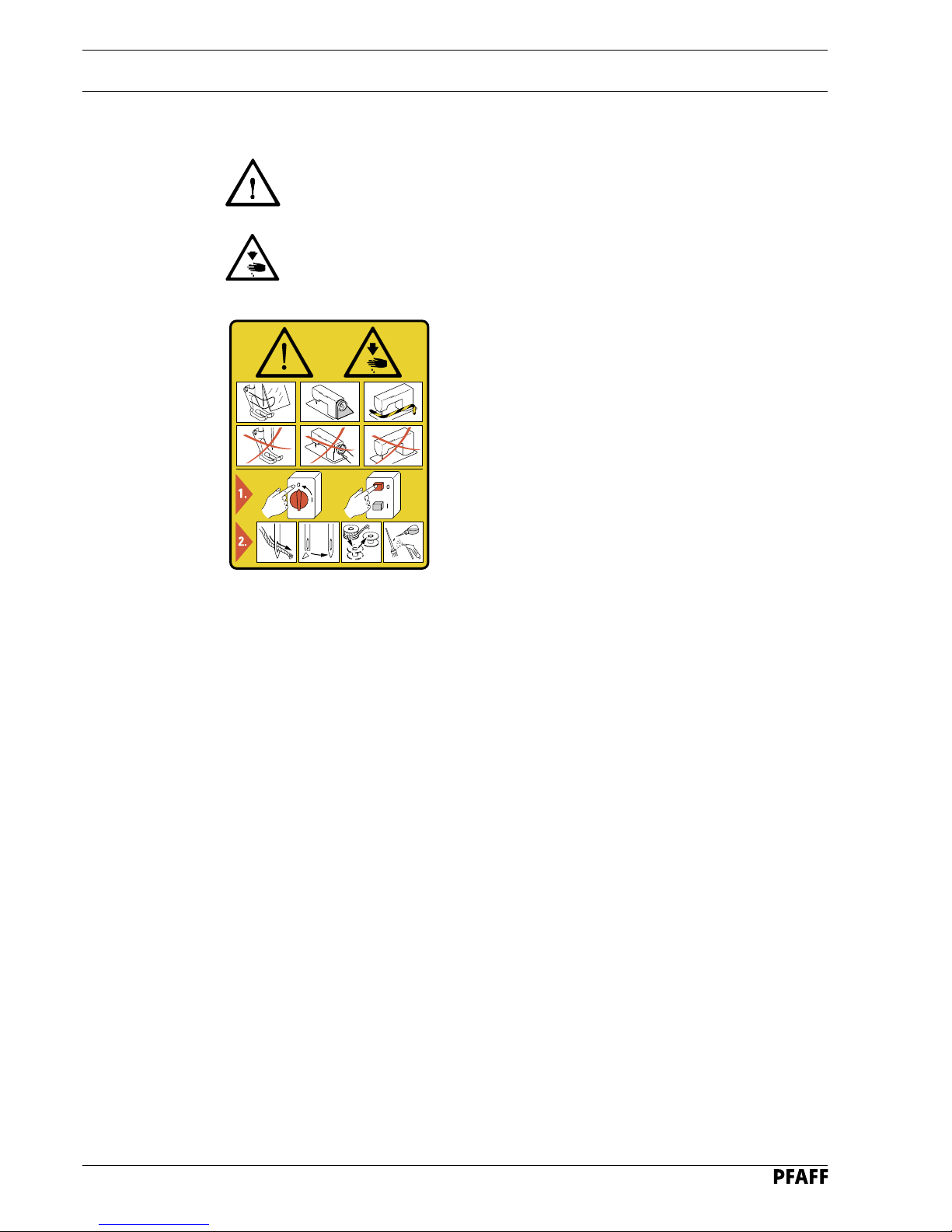
1.03 Safety symbols
Danger!
Points to be observed.
Danger of injury for operating and specialist personnel!
1.04 Important points for the user
● This Instruction Manual is a component part of the machine and must be available to the
operating personnel at all times.
The Instruction Manual must be read before operating the machine for the first time.
● The operating and specialist personnel is to be instructed as to the safety equipment of
the machine and regarding safe work methods.
● It is the duty of the user to only operate the machine in perfect running order.
● It is the obligation of the user to ensure that none of the safety mechanisms are
removed or deactivated.
● It is the obligation of the user to ensure that only authorised persons operate and
work on the machine.
Further information can be obtained at your PFAFF agent.
I
Caution
Do not operate without finger guard and safety devices.
Before threading, changing bobbin and needle, cleaning
etc. switch off main switch.
Page 7

Safety
1 - 3
1.
05 Operating and specialist personnel
1.05.01 Operating personnel
Operating personnel are persons responsible for the equipping, operating and cleaning of
the machine as well as taking care of faults arising in the sewing area.
The operating personnel is obliged to observe the following points and must:
● always observe the Notes on Safety in the Instruction Manual!
● never use any working methods which could limit the level of safety in using the
machine!
● not wear loosely fitting clothing or jewellery such as chains or rings!
● also ensure that only authorised persons have access to the potentially dangerous area
around the machine!
● always immediately report to the person responsible any changes in the machine which
may limit its safety!
1.05.02 Specialist personnel
Specialist personnel are persons with a specialist education in the fields of electrics,
electronics and mechanics. They are responsible for the lubrication, maintenance, repair and
adjustment of the machine.
The specialist personnel is obliged to observe the following points and must:
● always observe the Notes on Safety in the Instruction Manual!
● switch of the On/Off switch before carrying out adjustments or repairs and ensure that it
cannot be switched on again unintentionally!
● never work on parts which are still connected to the power supply! Exceptions are
contained in the regulations EN 50110.
● when servicing or carrying out repairs on pneumatic devices, remove the machine from
the compressed air supply! The only exceptions to this are function checks.
● replace the protective coverings and close the electrical control box after all repairs or
maintenance work!
Page 8

Safety
1 - 4
1.06 Danger
A working area of 1 metre is to be kept free both in front of and behind the
machine while it is in operation so that it is always easily accessible.
Never reach into the sewing area while sewing! Danger of injury by the needle!
Never leave objects on the table or in the needle plate area while adjusting the
machine settings! Objects can become trapped or be slung away! Danger of
injury!
Page 9

Proper use
2 - 1
2 Proper use
The PFAFF 3827 -2/24 is a sewing machine for the closing of side and shoulder seams on
outerwear (e.g. suit jackets, skirt suits, overcoats). The shoulder seams, including bartacks
and application of fullness are produced automatically as mirror images. On the side seams
the fullness to be applied is switched on using a manual switch.
Any and all uses of this machine which have not been approved of by the
manufacturer are considered to be inappropriate! The manufacturer cannot be
held liable for any damage caused by the inappropriate use of the machine!
The appropriate use of the machine includes the observance of all operational,
adjustment, maintenance and repair measures required by the manufacturer!
Page 10

Specifications
3 Specifications
Sewing machine head:...................................... PFAFF 487 - 706 / 81 - 900 / 99 BS x N3,5
Stitch type:................................................................................................ 301 ( lockstitch )
Model:............................................................................................................................... B
Needle system:........................................................................................................ 134 KK
Needle thickness (Nm):.......................................................................................... 80 - 100
Thread thickness (Nm): ................................................................ max. 60 when synthetic
or comparable thicknesses of other types of thread
Top feed stroke:......................................................................................................... 2 mm
Clearance under the presser foot:.............................................................................. 7 mm
Max. speed: ........................................................................................................ 4800 spm
Max. stitch length: .................................................................................................. 4.5 mm
Sewing motor: ..................................................................................QE 5542-P138SE-Pb5
Maximum motor rpm:................................................................................................. 4000
Working noise level:
Emission at workplace at sewing speed of n = 4000 spm: .......................LpA < 79 dB ( A )
(noise measurement in accordance with DIN 45 635-48-A-1)
Dimensions of machine:
Length:................................................................................................................. 1365 mm
Width: .................................................................................................................... 950 mm
Height: ................................................................................. 1700 mm ( incl. spool holder )
Weight:
Net: .............................................................................................................. approx. 108 kg
Gross: ..........................................................................................................approx. 230 kg
Power supply: ................................................................................................ 230 V ± 10%
50 / 60 Hz, 1 Phase
Power supply frequency: .................................................................................... 50 / 60 Hz
Power input: ................................................................................................... max. 650 VA
Fuse protection: ............................................................................ 1 x 16 A, delayed action
Working air pressure:.................................................................................................. 6 bar
Air consumption:.................................................................................... ~1,6 l / work cycle
3 - 1
Page 11

Disposal of the machine
4 - 1
4 Disposal of the machine
● The proper disposal of the machine is the responsibility of the customer.
● The materials used on the PFAFF 3827 -2/24 are steel, aluminium, brass and various
plastics. The electrical equipment consists of plastics and copper.
● The machine is to be disposed of in accordance with the locally valid environmental
protection regulations.
Special care is to be taken that parts covrered with lubricants are separately
disposed of in accordance with the locally valid environmental protection
regulations!
Page 12

Notes on testing in accordance with EN 60204-1
5 Notes on testing in accordance with EN 60204-1
The PFAFF 3827 -2/24 was tested in accordance with EN 60204-1 before delivery. The
following tests were carried out on the machine:
● Continuous connection of the protective conductor systems
a ) Visual check
b ) Check of the connection of the protective conductor
● Insulation check
● Voltage check
● Function check
5 - 1
Page 13

Transport packaging and storage
6 - 1
6 Transport packaging and storage
6.01 Transport to the customer’s premises
Within Germany, the machine is delivered without packaging. Machines to be exported are
packaged.
6.02 Transport within the customer’s premises
The manufacturer carries no liability for transport within the customer’s premises. Care is to
be taken to transport the machine in an upright position.
6.03 Disposal of the packaging
The packaging of the machine consists of wood, paper, cardboard and VCE fibre. The proper
disposal of the packaging is the responsibility of the customer.
6.04 Storage
The machine can be stored for up to 6 months if not in use. During this time it should be
protected from dust and moisture.
For longer storage the individual parts of the machine, especially the moving parts, should
be protected against corrosion e.g. by a film of oil.
Page 14

Explanation of the symbols
7 Explanation of the symbols
In the following section of this Instruction Manual, certain tasks or important pieces of
information are accentuated by symbols. The symbols used have the following meanings:
Note, information
Operation, adjusting
Programming, preparing, positioning
Cleaning, care
Lubrication, greasing
Servicing, repairing,
adjustment, maintenance
7 - 1
Page 15
Operational controls and optical displays
8 - 1
8 Operational controls and optical displays
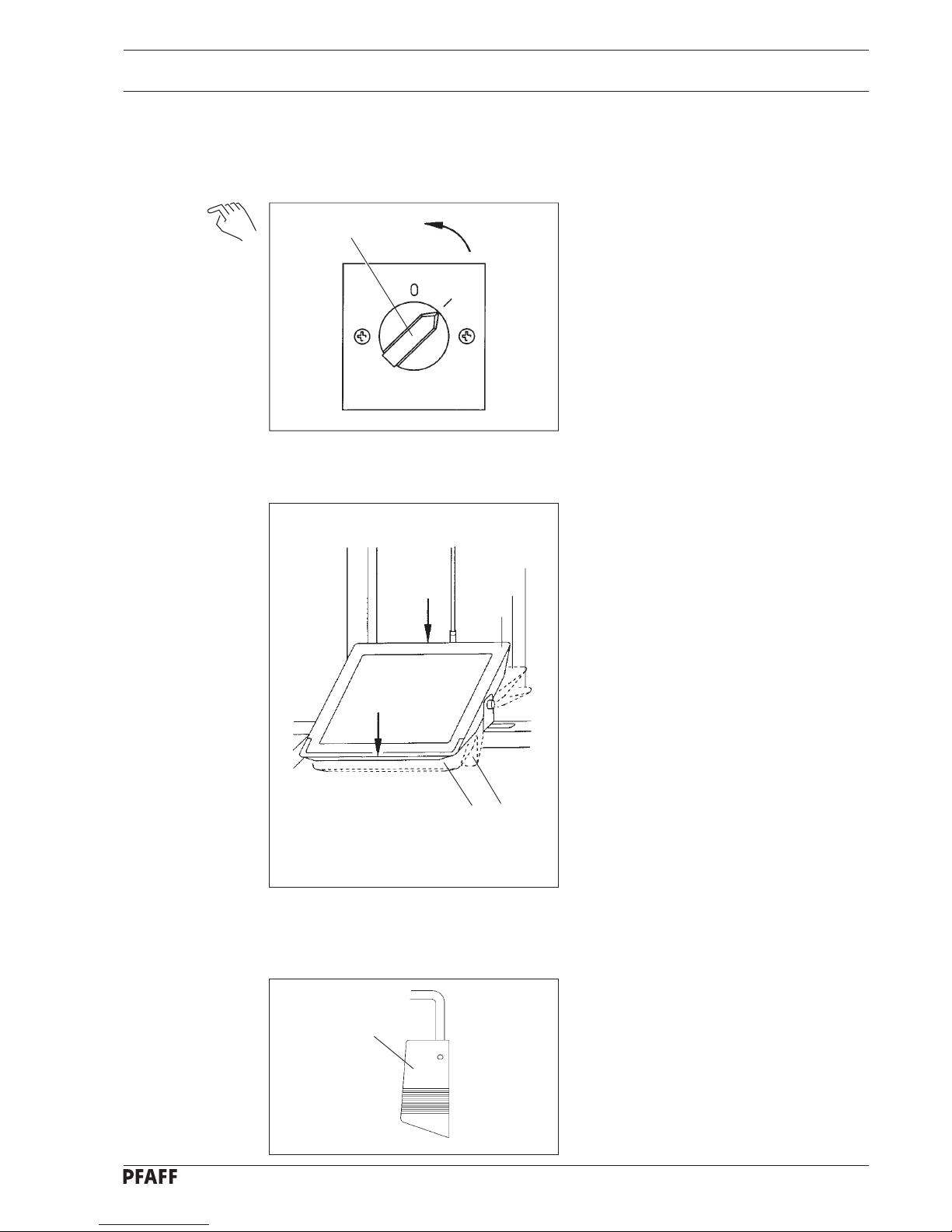
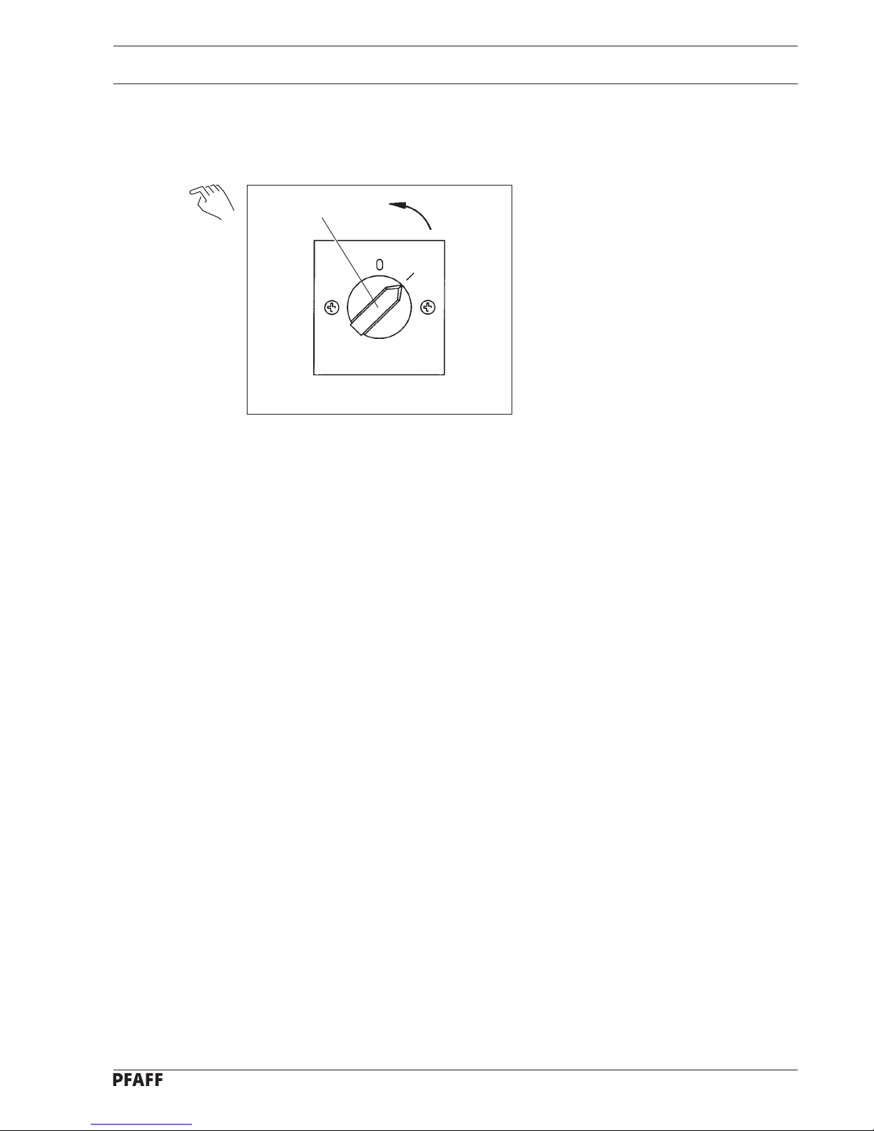
8.01 On/Off switch
● Turn the machine on and off by turning
the On/Off switch 1 to „1“ for on and
„0“ for off.
8.02 Functions of the pedal
0 = Machine stop
The position of the presser foot and
needle are dependent on the position
of the switches 1 and 3 on the quick
control panel (see chapter 8.05
Functions of the quick control
panel).
+1= Depends on the position of switch 1
on the quick control panel:
Switch 1 up - presser foot down
Switch 1 down - sew
+2= Sew up to the max. speed in 12
steps.
-1 = Depends on the position of switch 1
on the quick control panel:
Switch 1 down - presser foot up.
-2 = End bartack and trim thread in seam
segment 0 (semi-automatic
operation).
8.03 Functions of the knee lever
● By activating the knee lever 1 the
automatic function is engaged.
1
Fig. 8 - 02
Fig. 8 - 03
+2
+1
0
-2
-1
1
Fig. 8 - 01
Page 16
Operational controls and optical displays
8 - 2
8.04 Functions of the hand buttons
Hand button 1 = Reset; return to semi-
automatic operation.
Hand button 2 = Turn fullness on and
off.
Hand button 3 = Intermediate bartack.
The machine sews
backwards as long as
this button is pressed.
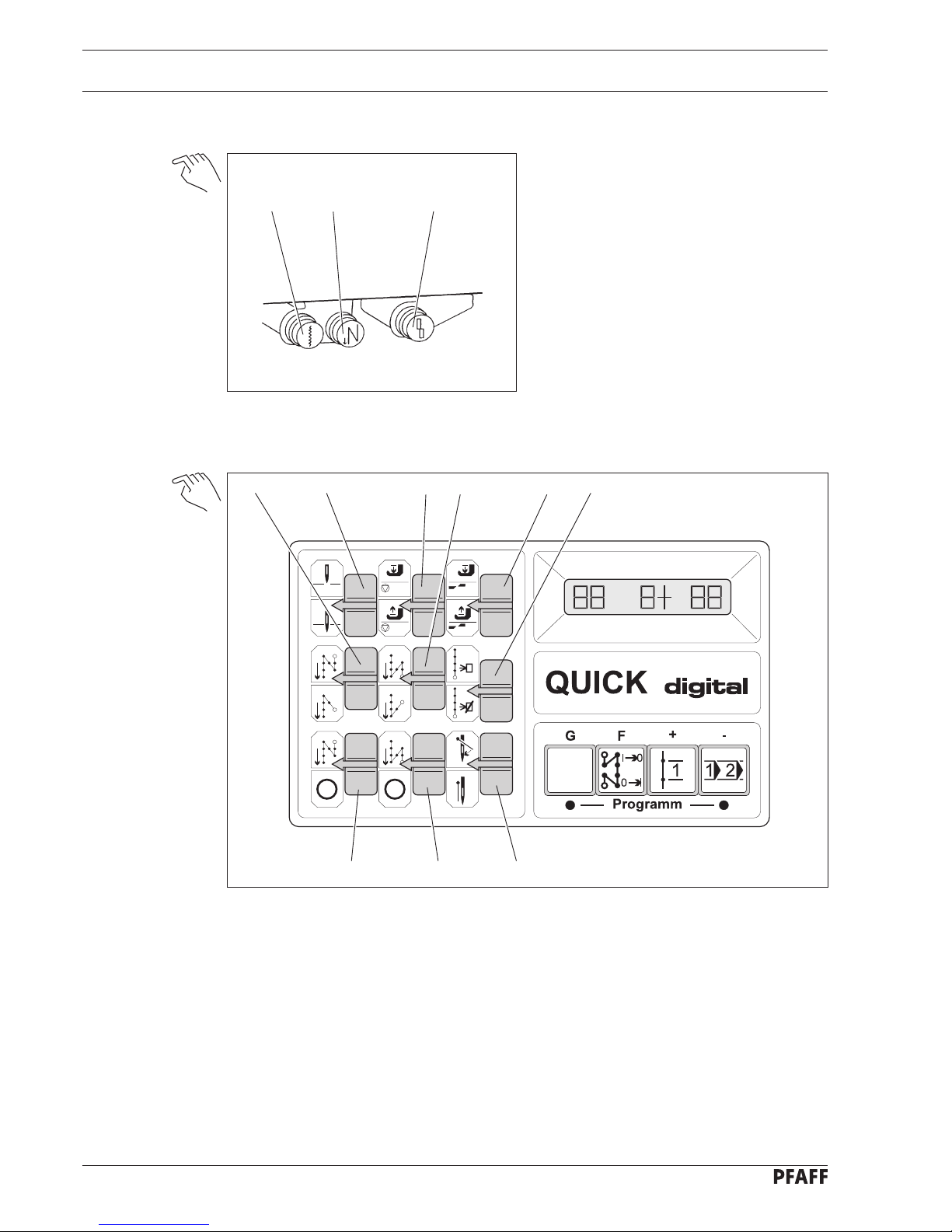
8.05 Functions of the quick control panel
Switch functions
Switch 1 = presser foot up/down with pedal at 0
Switch 2 = presser foot up/down at sewing stop
Switch 3 = needle up/down with pedal at 0
Switch 4 = single/double start bartack
Switch 5 = single/double end bartack
Switch 6 = automatic operation / semi-automatic operation
Switch 7 = start bartack on/off
Switch 8 = end bartack on/off
Switch 9 = thread wiper on/off (no function)
Fig. 8 - 04
2
1
3
Fig. 8 - 05
615234
9
87
Page 17
Operational controls and optical displays
8 - 3
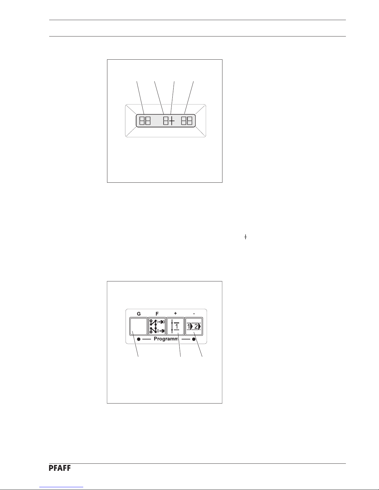
Messages in the display
a = counter value of stitch counter Z1
b = current seam segment:
Seam segment 0 for semi-automatic
operation, seam segments 1- 6 for
automatic operation:
0 = seam segment 0
1 = seam segment 1 of the 1st
shoulder seam
2 = seam segment 2 of the 1st
shoulder seam
seam with fullness
3 = seam segment 3 of the 1st
shoulder seam
4 = seam segment 4 of the 2nd
shoulder seam
5 = seam segment 5 of the 2nd
shoulder seam
seam with fullness
6 = seam segment 6 of the 2nd
shoulder seam
c= for fullness on
d = counter value of stitch counter Z2
Programming buttons on the quick control panel
Button G = positionwise switching to the
stitch counters Z1 and Z2; the
current position blinks in the
display.
Button + = alter selected positions
Button - = alter selected positions
Fig. 8 - 06
G
+
_
ab c
d
Fig. 8 - 07
Page 18
Mounting and initial operation
9 Mounting and initial operation
This machine may only be mounted and put into operation by qualified
specialists! All relevant safety regulations are not to be adhered to!
9.01 Mounting
Connections for electrical and compressed air supplies must be available at the machine’s
location (see chapter 3 Specifications).
A solid, horizontal surface and adequate lighting must also be guaranteed.
9.02 Initial operation
● Check the machine for any possible damage, especially the electrical and pneumatic
leads.
● Clean the machine thoroughly and then oil it (see chapter 13 Maintenance and Care).
● Connect the machine to the power supply.
● Connect the machine to the compressed air supply. The manometer should display an
air pressure level of. 6 bar. Adjust to this value if necessary.
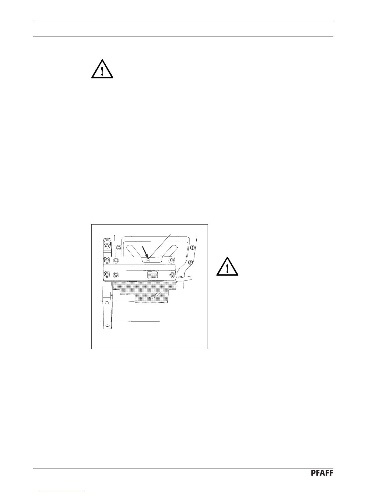
● Before the initial operation remove the
stopper from hole 1.
The stopper serves only to
secure the machine for
transport and must not be used
while sewing!
Abb. 9 - 01
1
9 - 1
Page 19
Switching the machine on/off
10 - 1
10 Switching the machine on/off
10.01 On/Off switch
● Turn the machine on and off by turning
the on/off switch 1 to „1“ for on and „0“
for off.
Fig. 8 - 01
1
Page 20
Preparation
11 - 1
11 Preparation
11.01 Inserting the needle
Turn the machine off!
● Bring the needle bar into its highest
position.
● Loosen the needle retaining screw 1.
● Insert the needle 2 as far as possible.
● The long needle-groove must be facing
left when looking in the direction of
sewing.
● Tighten the needle retaining screw 1.
Attention:Needle point and
knife blade! Danger of injury!
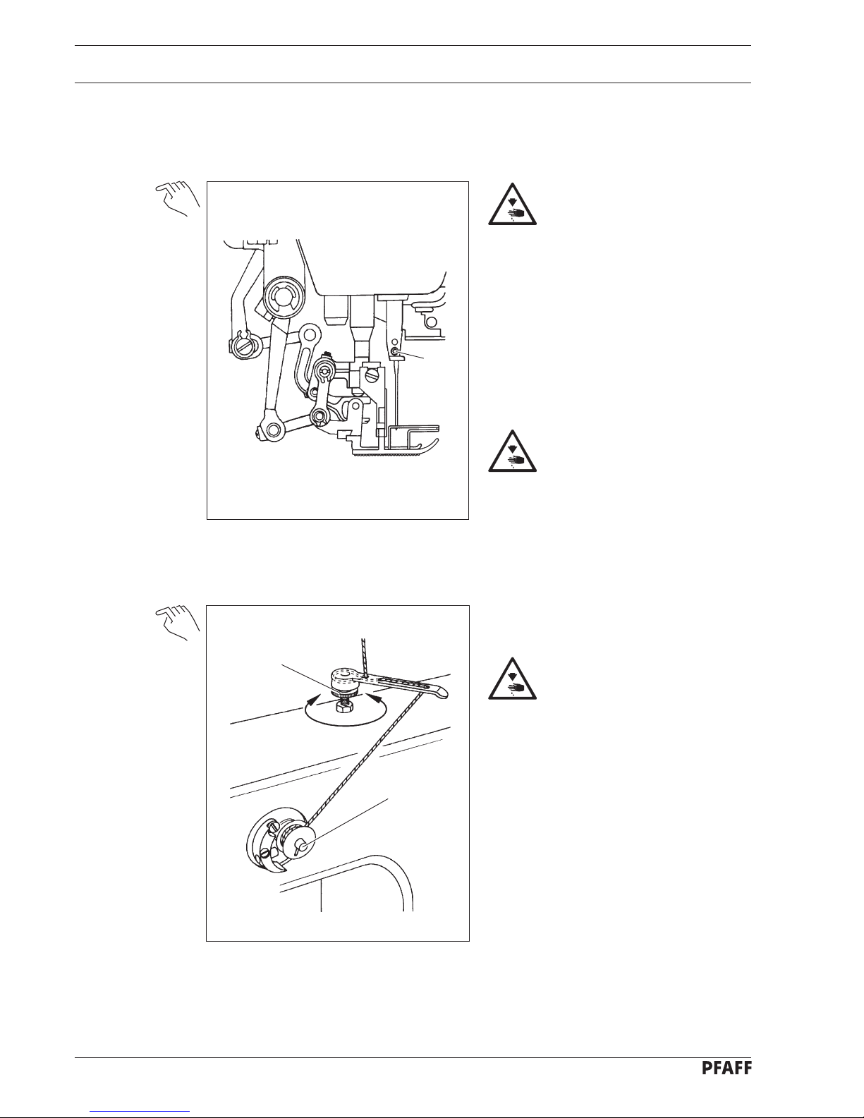
11.02 Winding the bobbin thread, adjusting the thread tension
● Set the bobbin winder into gear by
pressing in the bobbin winder spindle 1.
Papidly rotating bobbin!
Danger of Injury!
● Regulate the thread tension by turning
the milled screw 2.
Fig. 11 - 01
1
Fig.11 - 02
+
_
1
2
Page 21

Preparation
11.03 Threading the bobbin case, adjusting the thread tension
Turn the machine off!
● Insert the bobbin into the bobbin case.
● Thread the bobbin case in accordance
with Fig. 11-03.
● Adjust the thread tension by turning
screw 1.
● Use the enclosed tool for this process.
11.04 Inserting the bobbin case
Turn the machine off!
● Remove the bobbin case 1 with the bobbin.
● Change the bobbin (see chapter 11.03 Threading the bobbin case).
● Insert the bobbin case 1 into the bobbin case carrier 2.
11 - 2
Fig. 11 - 03
1
+
5 cm
_
Fig. 11 - 04
1
2
Page 22

Preparation
11 - 3
11.05 Threading the needle thread, adjusting the thread tension
● Thread the needle thread in accordance
with Fig. 11- 05.
● Adjust the needle thread tension by
turning the milled screw 1.
The needle is to be threaded
from left to right!
Do not operate the machine
without the take-up-lever
guard 2! Danger of injury
through the up and down
movement of the take up lever!
11.06 Pre-selecting the stitch length and fullnes
● To adjust the stitch length, move stitch
length controls 1 and 2 together.
● Pre-select fullness with adjustment
lever 3.
Fig. 11 - 05
+
_
6 cm
2
1
Fig. 11 - 06
3
2
1
Page 23

Preparation
11.07 Adjusting the edge stop
● Move the edge stop 1 by turning the milled nut 2.
● To sew without an edge stop 1, swing the lever 3 away.
11 - 4
Fig. 11 - 07
2
3
1
Page 24

Programming and sewing
12 Programming and sewing
With this machine the fullness is applied to the top layer of material. Therefore,
take care to ensure that the workpiece is appropriately inserted.
12.01 Semi-automatic operation
Programming and sewing
To select semi-automatic sewing, switch 6 must be down. During semi-automatic operation
switches 4, 5, 7 and 8 should be up (see Fig. 8 - 05). The positions of switches 1, 2, 3 and 9
can be chosen at your discretion.
Change to programming mode with button G and move to the position of the stitch counter
which have to be altered with button F.
The current position blinks.
Alter the current position with buttons + and -.
Exit from programming mode by pressing button G again.
12 - 1
Fig. 8 - 05
615234
9
87
Page 25

Programming and sewing
Function summary
● Program the stitch counter.
● Insert the workpiece - 1st side seam.
● Sew the start bartack. Trigger the bartack function with the pedal.
● Close the rest of the seam.
● Apply fullness if desired. To do so press the hand button for fullness. The button lights
up. A appears in the display.
● Sew an end bartack at the end of the material. Trigger the bartack function with the
pedal.
● Cut the threads at the end of the seam. Trigger the thread trimming function with the
pedal.
● Start the automatic function by pressing the knee lever with the right knee.
● Insert the workpiece - 1st shoulder seam.
● Close the 1st shoulder seam. The start bartack, fullness and end bartack are completed
automatically one after the other. Seam segments 1 to 3 are shown in the display. When
fullness is being applied a is shown in the display and the fullness button is lit.
● Insert the workpiece - 2nd shoulder seam.
● Close the 2nd shoulder seam. The 2nd shoulder seam is sewn automatically as a mirror
image of the 1st shoulder seam. In the display the seam segments 4 to 6 are shown.
When fullness is being applied a is shown in the display and the fullness button is lit.
After completing seam segments 4 to 6 the seam segment 0 appears in the display.
● Insert the workpiece - 2nd side seam.
● Sew the start bartack.
● Close the seam. Apply fullness if desired.
● Sew the end bartack.
● Trim thread.
12 - 2
Fig. 12 - 01
Activate knee lever
End bartack and
thread trimming
(pedal -2)
1st side seam
with fullness if desired
Start bartack
4
5
6
3
1
2
Seam segments
Seam
segment 0
End bartack and
thread trimming
(pedal -2)
2nd side seam
with fullness if desired
Start bartack
1st and 2nd shoulder seams
Start bartack
Seam with fullness
Automatic
end bartack and
thread trimmer
Seam segments
Page 26

Programming and sewing
12.02 Automatic operation
Function summary
In automatic operation, only shoulder seams can be sewn one after another. See chapter
12.01 Semi-automatic operation for further function summary.
Programming and sewing
To select automatic operation, switch 6 (see Fig. 8 - 05) must be up. For further
programming see chapter 12.01 Semi-automatic operation.
12 - 3
Page 27

Care and maintenance
13 - 1
13 Care and maintenance
Clean the hook and the hook compartment............................................................ daily
Lubricate ........................................................................................................... monthly
Lubricate the top feed joints ............................................................................... weekly
Check the air pressure .......................................................................... daily before use
13.01 Cleaning
Turn the machine off!
● Lay the machine head on its back.
● Clean the hook and the hook compartment daily, more often when in continuous
operation.
● Return the machine head to its upright position with both hands.
Danger of crushing between machine head and table top!
13.02 Lubricating
Turn the machine off!
Only use oil with a mean
viscosity of 10.0 mm2/s at
40°C and a density of 0.847 g/
cm3 at 15°C.
We recommend PFAFF
sewing machine oil.
Part no. 280-1-120 105.
● Lay the machine head on its back.
● Fill the oil reservoir 2 up to the upper
marking 3 through the hole 1.
● Return the machine to its upright position with both hands.
Danger of crushing between machine head and table top!
With the machine working 8 hours a day, the oil reservoir is to be checked once a month
and refilled if necessary.
1
3
2
Fig. 9 - 01
Page 28

Care and maintenance
13 - 2
● The top feed joints are to be given one
drop of oil each, once a week. (see Fig.
13 - 02 - arrows)
13.03 Checking the air pressure
● Check the air pressure at the manometer
before every use of the machine.
● The manometer 1 must show a pressure
of approx. 6 bar.
● Adjust to this value if necessary.
● To do so lift button 2 and turn it until the
manometer shows approx. 6 bar.
When the air pressure is turned off,
condensation drops out of valve 3. Place a
suitable container under the valve!
Fig. 13 - 01
Fig. 13 - 02
3
2
1
Page 29

Adjustment
14 - 1
14 Adjustment
On the PFAFF 487 - 706/.. no c-clamps may be attached to the needle bar as
this would damage the special coating on the needle bar.
All adjustments in these adjustment instructions are based on a completely
installed machine. Covers on the machine which have to be removed and
replaced for checks and adjustment work are not mentioned. The screws and
nuts in brackets are attachments of machine parts which are to be loosened
before making the adjustment and tightened again when the adjustment is
complete.
14.01 Tools, gauges and other accessories
● Screwdrivers with blade width from 2 to 10 mm
● Screwdrivers with blade width from 7 to 14 mm
● Allan keys from 1.5 to 6 mm
● Metal rule, Part No. 08-880 218-00
● Rig pin 5 mm diameter, Part No. 13-030 341-05
● Adjustment gauge, Part No. 61-111 642-19
● Alignment gauge, Part No. 91-069 375-15
● Gauge foot, Part No. 61-111 639-20
● Needles, system 134KK
● Sewing thread and test material
● Hook oil: PFAFF sewing machine oil Part No. 280-1-120 105
mean viscosity of 10.0 mm2/s at 40°C, density 0.847 g/cm3 at 15°C
14.02 Abbreviations
TDC = top dead center
BDC = bottom dead center
Page 30

Adjustment
14 - 2
14.03 Check and adjustment aid
By placing pegs in holes 1 and 3 - 6 the required needle bar positions can be
exactly fixed.
● Turn the handwheel until the needle bar has approximately reached the required position.
● Place the 5 mm rig pin in the appropriate hole and put pressure on it.
● Turn the handwheel forwards and backwards a little until the rig pin moves into the slot
in the crank behind the bearing plate, thus blocking the machine.
Hole 1 = 0.6 mm after the top dead center of the needle bar (0.6 a. TDC)
Hole 3 = 0.6 mm after the bottom dead center of the needle bar (0.6 a. BDC)
Hole 4 = 1.8 mm after the bottom dead center of the needle bar (needle rise)
Hole 5 = Top dead center of the needle bar (TDC)
Hole 6 = 4 mm after the bottom dead center of the needle bar (4 a. BDC)
Fig. 14 - 01
5
1
4
6
3
Page 31

Adjustment
14 - 3
14.04 Pre-adjusting the needle height
Requirement
With the needle bar at its BDC there must be a clearance of approx. 16.5 mm between the
bottom edge of the needle bar and the needle plate.
● Move the needle bar 1 (screws 2) in accordance with the requirement while taking care
to ensure that the needle retaining screw 3 is pointed to the left viewed in the direction
of feed.
3
1
2
5
1
4
6
3
16.5 mm
Fig. 14 - 02
Page 32

Adjustment
14 - 4
14.05 Centering the needle in the needle hole
Requirement
The needle must enter exactly the middle of the needle hole.
● Bring the needle into a position directly over the needle hole.
● Loosen screws 1, 2 and 3.
● Move the needle bar frame 4 into a position according with the requirement in both the
sewing direction and across the sewing direction.
● Tighten screw 3 tightly and screw 2 just a little.
● Using screw 1 pull the guide pin behind screw 1 towards the eye of the needle bar frame
and tighten it.
● Remove the needle.
● Loosen screw 2. Turn the handwheel a few rotations (to avoid any tension that may
exist) and tighten screw 2.
1
4
3
2
Fig. 14 - 03
Page 33

Adjustment
14 - 5
14.06 Zeroing the bottom feed dog
Requirement
With the stitch length set at 0 the bottom feed dog should not move laterally when the
handwheel is turned.
14.06.01 Adjustment with the gearbox housing closed
● Raise the presser foot.
● Turn bush 2 (screw 3) so that the marking 4 is pointing downwards and the edge of the
notched surface is at a 45° angle to the front of the machine.
For the final adjustment see chapter 14.18 Synchronizing the vibrating presser.
● Place a suitable pin or Allan key in hole 5 of the tensioning hoop 6 and hold the shaft 7
still with it.
● Turn the shaft 7 (screw 8) in accordance with the requirement.
56
8
7
45°
Fig. 14 - 04
2
3
4
Page 34

Adjustment
14 - 6
14.06.02 Adjustment with the gearbox housing open
● Raise the presser foot.
● Turn bush 2 (screw 3) so that the marking 4 is pointing downwards and the edge of the
notched surface is at a 45° angle to the front of the machine.
For the final adjustment see chapter 14.18 Synchronizing the vibrating presser.
● Turn the crank 5 (screw 6) in accordance with the requirement.
45°
2
3
6
5
Fig. 14 - 05
4
Page 35

Adjustment
14 - 7
14.07 Driving motion of the bottom feed dog
Requirement
With the largest stitch length set and the needle bar 0.6 mm after the TDC (hole 1) the
bottom feed dog must not move when the crank 3 is turned in the direction of the arrow.
● Turn the feed driving eccentric 1 (screws 2) in accordance with the requirement while
taking care that the notch in the feed driving eccentric is visible.
3
2
1
Fig. 14 - 06
Page 36

Adjustment
14 - 8
14.08 Lifting motion of the bottom feed dog
Requirement
With the stitch length set at 0 and the needle bar at 0.6 mm after the TDC (hole 1) the
bottom feed dog must be at its TDC.
The notch in the feed lifting eccentric 1 must be approx. vertically underneath the middle
of the axle.
● Turn the feed lifting eccentric 1 (screws 2) in accordance with the requirement while
taking care to ensure that there is a little play between the feed lifting eccentric 1 and
the connecting rod behind it.
1
2
Fig. 14 - 07
Page 37

Adjustment
14 - 9
14.09 Height of the bottom feed dog
Requirement
With the stitch length set at „0“ and the needle bar 0.6 mm after its TDC (hole 1) the feed
dog must:
1. be centered in the needle plate cutout, when viewed from the side and from the
direction of feed.
2. be at its upper point of reversal and touching the adjustment gauge along its entire
length.
● Move the feed dog carrier 1 (screw 2) in accordance with requirement 1.
● Allow the presser foot to rest on the gauge.
● Turn eccentric 3 (screw 4) and eccentric 5 (screw 6) in accordance with requirement 2.
Take care that eccentrics 3 and 5 are not turned 180°.
1,16
x
=
x
0,72
Fig. 14 - 08
543
61
2
Page 38

Adjustment
14 - 10
14.10 Clearance between presser foot and needle plate
Requirement
With the presser bar lifter 1 raised there must be a distance of 5 mm between the presser
foot and the needle plate.
● Screw on the gauge foot 13.
● Allow the gauge foot to rest on the needle plate using the presser bar lifter 1.
● Reduce the pressure on the presser bar by loosening the adjusting screw 2 (milled
nut 3).
● Loosen screw 4 and press pin 5 out.
● Swing the connecting joint 6 out of the fork of lever 7.
● Bring the vibrating presser to its highest point by turning the handwheel and raise the
gauge foot.
7
4
5
9
10
6
7
13
8
6
2
3
12
11
1
10
7
Fig.14 - 09
Page 39

Adjustment
14 - 11
● Raise the presser bar 8 and place the 5 mm adjustment gauge underneath the gauge
foot.
● Loosen screw 9 and press the pin out 10.
● Loosen screw 11.
● Position the gauge foot so that its edge is parallel to the needle plate cutout.
● Lower the lifting piece 12 until it comes to rest and tighten screw 11.
Do not mount pins 5 and 10.
Leave screws 4 and 9 loosened for the following adjustment.
Page 40

Adjustment
14 - 12
14.11 Adjusting the floating foot
Requirement
1. With the gauge foot 1 resting on the needle plate, screw 2 must be resting on the stop.
2. With the floating foot 4 resting on the needle plate 5 and the bottom feed dog
underneath the top edge of the needle plate there must be a distance of 0.5 mm
between stop 6 and guide 7.
● Remove the floating foot 4 and replace it with the gauge foot 1.
● Bring the gauge foot 1 to a resting position on the needle plate 5 using the presser bar
lifter 3.
● Adjust screw 2 in accordance with requirement 1.
● Remove the gauge foot 1 and replace it with the floating foot 4.
● Bring the floating foot 4 to a resting position on the needle plate 5 using the presser bar
lifter 3.
● Adjust screw 2 in accordance with requirement 2.
Take care to ensure that the presser foot pressure is stronger than the
pressure of the floating foot spring.
1
0.5 mm
7
6
5
4
3
2
Fig. 14 - 10
Page 41

Adjustment
14 - 13
14.12 Top feed driving and connecting levers
Requirement
All moving parts of the top feed system must move freely and without play.
● Lower the sewing foot using the presser bar lifter 1.
● Loosen screw 2.
● Swing the connecting joint 3 into the fork of lever 4 and insert pin 5. Ensure that the
parts move freely. If necessary adjust lever 4.
● Tighten screw 11.
● Set the stitch length at „0“.
● Center the vibrating presser foot in the presser foot cutout in the direction of sewing and
tighten screw 2.
● Loosen screw 6.
● Align the hole in lever 7 with the hole in lever 8. If necessary move or adjust lever 7.
● Insert pin 9, with its largest eccentricity facing downwards, into the holes of levers 7 and
8 and tighten screw 10.
● Press lever 7 as far as it will go in the direction of feed and tighten screws 6 and 11.
● Adjust the vibrating presser foot laterally so that it is not touching the presser foot
(screw 12).
12
11
6
7
1
8
10
4
2
954 3
Fig. 14 - 11
Page 42

Adjustment
14 - 14
14.13 Zeroing the top feed motion
Requirement
With the stitch length and the top feed set at 0 and with the alignment gauge 8 attached
there should be no movement of the feed driving lever 18 when the handwheel is turned.
7
6
5
12
14
15
17
16
8
13294
18
Fig. 14 - 12
Page 43

Adjustment
14 - 15
● Raise the presser foot.
● Loosen screws 1 and 2.
● Place crank 3 parallel to crank 4 and tighten screw 2.
● Set the stitch length controls 5, 6 and 7 at 0.
● Place the alignment gauge 8 onto the pins 9.
● Turn the handwheel and turn crank 11 (screw 10) so that the vibrating presser foot does
not move.
● Loosen nut 12.
● Move the pull rod 14 up and down several times while moving lever 15 (screw 13) so
that the vibrating presser foot does not move.
● Bring the pull rod 14 to a position where it touches the top of the elongated hole and
tighten nut 12.
● Set the stitch length controls 5,6 and 7 at 3.
● Set crank 16 lengthwise and crosswise against crank 17 and tighten screw 1.
● Remove the alignment gauge 8.
11 10
13
Fig. 14 - 13
Page 44

Adjustment
14 - 16
14.14 Feeding motion of the vibrating presser
Requirement
With the machine set at its longest stitch length and the needle bar positioned 0.6 mm
past its TDC (hole 1) the vibrating presser 3 must not move when crank 4 is moved up and
down.
● Raise the presser foot.
● Turn the feed driving eccentric 1 (screws 2) in accordance with the requirement. Ensure
that the notch (see arrow) is visible.
2
1
4
3
Fig. 14 - 14
Page 45

Adjustment
14 - 17
14.15 Vibrating presser lift
Requirement
With the stitch length set at 0, the presser foot resting on the needle plate and the
vibrating presser at its TDC, there must be the following clearance between the needle
plate and the vibrating presser foot:
● 1.3 mm with the vibrating presser operating behind the needle.
● 2.0 mm with the vibrating presser operating in front of the needle.
● Increase the pressure on screw 1 (nut 2) a little.
● Lower the presser foot until it rests on the needle plate.
● Move the eccentricity of pin 3 (screw 4) towards the needle bar (see arrow).
● Turn the eccentricity of pin 5 (screw 6) downwards.
● Turn the handwheel until the connecting lever 7 is at its rear point of reversal.
● Press the connecting lever 7 (screw 8) to the rear and place the corresponding feeler
gauge (see requirement) between the vibrating presser foot and the needle plate.
● If necessary, re-adjust eccentric pin 5 (screw 6) by turning it accordingly.
8
7
5
6
4
3
1
2
3
4
1.3 mm bzw.
2.0 mm
Fig. 14 - 15
Page 46

Adjustment
14 - 18
14.16 Vibrating presser lifting motion
Requirement
With the stitch length set at 2 and the ascending feed dog at the top edge of the needle
plate, the vibrating presser must be touching the feed dog (see arrow).
● Turn eccentric pin 1 (screw 2) in accordance with the requirement.
2
1
Fig. 14 - 16
Page 47

Adjustment
14 - 19
14.17 Position of the vibrating presser
Requirement
With the bottom feed dog at its top point of reversal the vibrating presser must be parallel
to the bottom feed dog.
● Turn eccentric pin 1 (screw 2) in accordance with the requirement.
2
1
Fig. 14 - 17
Page 48

Adjustment
14 - 20
14.18 Synchronizing the vibrating presser
Requirement
With the stitch-length and vibrating-presser-stroke adjustment levers all at 3 the vibrating
presser and the bottom feed dog must work with the same feed motion when the
handwheel is turned.
● Press the adjustment levers downwards.
● Loosen nut 1.
● Set the adjustment levers 3 at „3“.
● Move the pull rod 2 in the elongated hole in accordance with the requirement and
tighten nut 1.
2
1
3
Fig. 14 - 18
Page 49

Adjustment
14 - 21
14.19 Matching forward and reverse stitch lengths
Requirement
With the stitch length set at „3“ the forward feed must match the reverse feed.
● Turn bush 1 (screw 2) in accordance with the requirement.
Make sure that the eccentricity of the bush 1 is facing downwards.
1
2
Fig. 14 - 19
Page 50

Adjustment
14 - 22
14.20 Eccentric hook shaft bearing
Requirement
1. The notch in bearing 3 (see arrow) must be visible from below.
There must be a slight but still noticeable play between gears 5 and 7.
2. With the hook lightly touching the spin disc 4 and the hook point opposite the center
line of the needle, there must be a clearance of less than 0.1 mm between the hook
point and the clearance cut of the needle.
3. Gear 5 must be flush with gear 7.
● Loosen screw 1 and both screws 2.
● Turn bearing 3 in accordance with requirement 1.
● Set the hook lightly against spin disc 4 and shift bearing 3, without turning it, in
accordance with requirement 2. Tighten screws 1 and 2.
● Position gear 5 (screws 6) in accordance with requirement 3.
5
6
7
3
142
max. 0.1 mm
Fig. 14 - 20
Page 51

Adjustment
14 - 23
14.21 Needle rise, final adjustment of the needle bar height and bobbin case
positioning finger
Requirement
With the needle bar at a position 1.8 mm past its BDC (hole 4):
1. the hook point must be opposite the center line of the needle, and the top edge of the
needle eye must be 0.8 mm below the bottom edge of the sewing hook.
2. There must be a clearance of 0.5 mm between the lug of the positioning finger 3 and
the inside edge of the positioning slot.
● Adjust the hook (screws 1) - without shifting it - and the needle bar (screws 2) - without
twisting it - in accordance with requirement 1.
● Set the lug of positioning finger 3 into the slot in the bobbin case carrier and adjust and
secure it in accordance with requirement 2.
2
1
3
0.5 mm
Fig. 14 - 21
0.8 mm
Page 52

Adjustment
14 - 24
14.22 Height of the bobbin case opener
Requirement
At the left point of reversal of the bobbin case opener 3 the top edge of the bobbin case
opener finger must be 0.5 mm above the bottom edge of the bobbin case cam 4.
● Turn the bobbin case base 1 (screw 2) in accordance with the requirement.
1
2
3
4
0.5 mm
Fig. 14 - 22
Page 53

Adjustment
14 - 25
14.23 Position of bobbin case opener
Requirement
With the bobbin case opener 3 at its left point of reversal:
1. the front edge of the bobbin case opener finger must be approx. 0.6 mm behind the
front edge of the bobbin case cam 7.
2. The bobbin case carrier 6 must be approx. 0.3 mm from the positioning finger 8 and
screw 1 must be touching stop pin 5.
● Loosen screw 1 and then loosen screw 2 so that the bobbin case opener 3 is still just
held in position.
● Adjust the bobbin case opener 3 in accordance with requirement 1.
● Turn the bobbin case opener 3 in accordance with requirement 2 and tighten screw 2.
● Set fixing collar 4 against the bobbin case opener 3 and stop pin 5 and tighten screw 1.
3
2
4
1
5
2
3
7
0.6 mm
0.3 mm
3
6
8
Fig. 14 - 23
Page 54

Adjustment
14 - 26
14.24 Motion of bobbin case opener
Requirement
With the needle bar 1.8 mm past its BDC (hole 4) the bobbin case opener 3 must be at its
right point of reversal.
● Adjust the bobbin case opener eccentric 1 (screws 2) in accordance with the
requirement.
231
Fig. 14 - 24
Page 55

Adjustment
14 - 27
14.25 Needle thread tension release
Requirement
With the presser bar lifter 3 raised the tension discs must be at least 0.5 mm apart.
● Adjust the tension release lever 1 (screw 2) in accordance with the requirement.
● Lower the presser foot onto the needle plate. Now the tension must be fully active.
3
1
2
0.5 mm
Fig. 14 - 25
Page 56

Adjustment
14 - 28
14.26 Thread check spring and thread regulator
Requirement
1. The thread check spring 3 must have finished its stroke by the time the point of the
needle enters the material (stroke approx. 7 mm).
2. The thread regulator 4 must be fixed into the elongated hole so that the thread check
spring 3 moves 1 mm by the time the hook has widened the thread loop to its
maximum.
● Turn the thread tension 1 (screws 2) in accordance with requirement 1.
● Move the thread regulator 4 (screws 5) in accordance with requirement 2.
The stroke of the thread check spring 3 and the position of the thread regulator
4 are dependent on the type of thread and material used and should be
adjusted in accordance with the appearance of the seam.
7 mm
5
2
3
4
1
Fig. 14 - 26
Page 57

Adjustment
14 - 29
14.27 Bobbin winder
Requirement
With the bobbin winder engaged the winder spindle must be driven reliably. With the
bobbin winder disengaged, however, the friction wheel 5 must not touch the drive wheel 1.
The bobbin winder must wind evenly and stop automatically when the thread wound on
the bobbin has reached a point approx. 1 mm below the bobbin rim.
● Switch on the bobbin winder and adjust the drive wheel 1 (screw 2) in accordance with
the requirement.
● Place a bobbin on the winder spindle, thread the machine for bobbin winding and
switch on the bobbin winder.
● To adjust the amount of thread to be wound shift the regulating pin 3 (screw 4) in
accordance with the requirement.
1 mm
512
4
3
Fig. 14 - 27
Page 58

Adjustment
14 - 30
14.28 Position of vibrating presser in relation to presser foot
Requirement
With the presser foot raised by way of the lifting lever and the take up lever is at its top
point of reversal, the teeth of the vibrating presser 3 must not be below the presser foot
shoe 4.
● Turn the eccentric bush 1 (screw 2) in accordance with the requirement.
2
1
34
Fig. 14 - 28
Page 59

Adjustment
14 - 31
14.29 Pressure on vibrating presser and presser foot
Requirement
The proper feeding of the material must be ensured even at top sewing speed. There must
not be any pressure marks on the material.
● Pressure on vibrating pressure - Set regulating screw 1 flush with the top surface of the
machine housing.
● Pressure on presser foot - Turn regulating screw 2 (milled nut 3) until there is a clearance
of approx. 12 mm between the screw shoulder and the machine housing.
If necessary, the pressure on the vibrating presser and the presser foot can be
increased (+) or decreased (-).
+
+
_
1
2
3
_
12 mm
Fig. 14 - 29
Page 60

Adjustment
14 - 32
14.30 Limiting the stitch length
● Loosen screw 1 (accessible through the assembly hole) or screw it out according to the
limit to be set.
● Set the stitch length control lever 2 at the desired maximum stitch length.
● Set the limiting angle 3 from above so that it touches the control lever 2 and secure it (in
the desired position) by tightening screw 1 in either the lower or upper hole.
3
1
2
Fig. 14 - 30
Page 61

Adjustment
14 - 33
14.31 Lateral position of thread catcher
Requirement
The tip of the thread catcher 3 must be pointing at the center line of the needle; if required
however, it can be up to 0.3 mm to the left of this center line.
The thread catcher 3 must move without striking the bobbin case positioning finger 5.
● Disconnect linkage rod 1.
● Set the end of the cylinder plunger 2 flush with the face of nut 3 (nut 4).
● Bring the needle bar to its BDC and position the tip of the catcher 7 in front of the needle
by pushing the pull rod 6 upwards.
● Position the catcher 7 (screws 5) in accordance with the requirement making sure that
the catcher 7 is horizontal.
1
7 65
2
3
4
7
8
Fig. 14 - 31
Page 62

Adjustment
14 - 34
14.32 Point of reversal of thread catcher
Requirement
With the compressed air switched off and the cylinder plunger fully extended by hand
(front point of reversal of the catcher 4) the rear edge of the thread catcher cutout must be
1 to 1.4 mm beyond the front edge of the bobbin case positioning finger.
● Bring the needle bar to its TDC and re-connect the linkage rod 1.
● Bring the ball stud (nut 2) to the middle of the elongated hole.
● Extend the cylinder plunger fully by hand.
● Turn the linkage rod 1 (nuts 3, left and right hand thread!) in accordance with the
requirement.
1
3
2
4
1 - 1.4 mm
Fig. 14 - 32
Page 63

Adjustment
14 - 35
14.33 Knife
Requirement
There must be a clearance of approx. 4 mm between the needle and the cutting edge of
the knife 3.
● Disconnect the linkage rod 1 and bring the needle bar to its BDC.
● Position the catcher 5 directly in front of the needle and move the knife 3 (screw 2) in
accordance with the requirement.
Make sure that the right hand edges of the knife 3 and the catcher 5 are flush (see
arrow).
● Bring the needle bar to its TDC and push the catcher 5 fully forward.
● Place two threads in the cutout of the catcher 5 and carry out a cutting test.
● To correct: position the catcher 5 (screws 4) parallel to the cutting edge while making
sure to observe the requirement described in chapter 14.31 Lateral position of the
thread catcher!
● Place the stop 6 on the right hand bottom edge of the thread catcher 5 and tighten
screws 7.
● Re-connect the linkage rod 1.
2
3
5
4 mm
3
Fig. 14 - 33
4 7
6
1
Page 64

Adjustment
14 - 36
14.34 Needle thread tension release
Requirement
With the thread catcher at its rear point of reversal, finger 3 must be engaged and there
must be a clearance of 0.5 mm between the finger and the control cam 4.
With the tip of the finger 3 at the highest point of cam 4 the tension discs must be at least
0.5 mm apart.
● Fully retract the cylinder plunger 5 by hand.
● By turning screw 7 (nut 6) create a clearance of 0.5 mm between the finger 3 and the
control cam 4.
● Lower the presser foot onto the needle plate using the presser bar lifter.
● Pull the pull rod 2 (screw 1) downwards as far as it will go and secure it into place.
0.5 mm
2
1
0.5 mm
3
7
4
6
5
3
4
Fig. 14 - 34
Page 65

Adjustment
14 - 37
14.35 Synchronizer
Requirement
When stopping sewing, the machine must position itself at approx. 4 mm after the BDC of
the needle bar.
After trimming the thread the machine must position itself in the TDC of the take-up lever.
When pressing the pedal backwards the plunger of the cylinder must extend when the
needle bar is 20 - 22 mm after its BDC.
● For the adjustment see the instruction manual of the motor manufacturer.
Page 66

G.M. PFAFF KAISERSLAUTERN
INDUSTRIEMASCHINEN AG
Postfach 3020
D-67653 Kaiserslautern
Königstr. 154
D-67655 Kaiserslautern
Telefon: (0631) 200-0
Telefax: (0631) 17202
E-Mail: info@pfaff-industrial.com
Gedruckt in der BRD
Printed in Germany
Imprimé en R.F.A.
Impreso en la R.F.A.
 Loading...