

Page 1

-20/02
3819
INSTRUCTION MANUAL
-40/01
This instruction manual applies to machines
from the following serial numbers onwards:
2 808 742 and software version 0441/001.
296-12-19 290/002
Instruction Manual engl. 10.15
Page 2

This instruction manual applies for all of the models and subclasses listed in
Chapter 3 Technical Data.
The adjustment manual for the machine can be downloaded at no charge
at www.pfaff-industrial.de/de/service-support/downloads/technical. As an
alternative to the Internet download, the adjustment manual can also be
ordered under order no. 296-12-19 291/002.
Reprinting, copying and translation - including excerpts - from
PFAFF instruction books is permitted only with our prior approval
and listing of sources.
PFAFF Industriesysteme
und Maschinen GmbH
Hans-Geiger-Str. 12 - IG Nord
D-67661 Kaiserslautern
Page 3

Table of Contents
Contents ..................................................................................................Page
1 Safety .................................................................................................................................... 5
1.01 Directives ............................................................................................................................... 5
1.02 General safety instructions ....................................................................................................5
1.03 Safety symbols ...................................................................................................................... 6
1.04 Special points of attention for the owner-operator ................................................................6
1.05 Operating personnel and technical staff ................................................................................7
1.05.01 Operating personnel .............................................................................................................. 7
1.05.02 Technical staff ........................................................................................................................ 7
1.06 Danger warnings ....................................................................................................................8
2 Proper Use ............................................................................................................................9
3 Technical Data ...................................................................................................................10
3.01 PFAFF 3819 ......................................................................................................................... 10
4 Disposal of the Machine .................................................................................................... 11
5 Transport, Packaging and Storage ................................................................................... 12
5.01 Transport to the customer´s premises ................................................................................ 12
5.02 Transport within the customer´s premises .......................................................................... 12
5.03 Disposal of the packaging materials .................................................................................... 12
5.04 Storage ................................................................................................................................ 12
6 Work Symbols ....................................................................................................................13
7 Operating Controls ............................................................................................................14
7.01 Main switch ........................................................................................................................ 14
7.02 Light barrier ..........................................................................................................................14
7.03 Treadle ................................................................................................................................. 15
7.04 Control panel ........................................................................................................................16
7.04.01 Symbols on the display ........................................................................................................ 17
7.04.02 Plus/minus keys ................................................................................................................... 17
7.04.03 Function keys ....................................................................................................................... 18
8 Set-up and Initial Commissioning .................................................................................... 20
8.01 Set-up .................................................................................................................................. 20
8.01.01 Setting the table height ...................................................................................................... 20
8.01.02 Mounting the reel stand ...................................................................................................... 21
8.02 Connecting the plug-in connections and ground cable ........................................................ 22
8.03 Initial start-up ....................................................................................................................... 23
8.04 Switching the machine on/off ............................................................................................. 23
Page 4

Table of Contents
Contents ..................................................................................................Page
9 Set-up .................................................................................................................................. 24
9.01 Inserting the needle ............................................................................................................. 24
9.02 Threading the needle / adjusting the needle thread ............................................................ 25
9.03 Threading the looper thread / adjusting the looper thread ................................................... 26
9.04 Fitting the tape reel ..............................................................................................................27
9.05 Threading the tape into the pleating attachment ................................................................. 27
10 Production .......................................................................................................................... 28
10.01 Sewing – automatic mode ................................................................................................... 29
10.02 Sewing – manual mode .......................................................................................................30
10.03 Input mode ..........................................................................................................................31
10.04 Input mode ..........................................................................................................................33
10.05 Programming ....................................................................................................................... 34
10.07 Programming ....................................................................................................................... 35
10.08 Programming a trouser waistband .......................................................................................36
10.09 Parameter list ....................................................................................................................... 37
10.10 Program management .........................................................................................................40
10.10.01 Inserting and removing the SD memory card ...................................................................... 40
10.10.02 Displaying the machine directory .........................................................................................41
10.10.03 Displaying the SD card directory ..........................................................................................42
10.10.04 Copying program(s) to the SD card ......................................................................................43
10.10.05 Copying program(s) from the SD card. ................................................................................ 44
10.10.05 Deleting program(s) in the machine memory ...................................................................... 45
10.10.06 Deleting program(s) on the SD card .................................................................................... 46
10.10.07 Formatting the SD card ........................................................................................................47
10.10.08 Error messages .................................................................................................................... 48
11 Maintenance and Care .......................................................................................................51
11.01 Maintenance intervals .......................................................................................................... 51
11.02 Cleaning the machine .......................................................................................................... 51
11.03 Checking / topping up the oil level of the oil tank for the front parts ................................... 52
11.04 Checking / topping up the oil level of the gear mechanism ................................................. 53
11.05 Checking / setting the air pressure ...................................................................................... 54
11.06 Emptying / cleaning the maintenance unit´s water tank ...................................................... 54
12 Wearing Parts ..................................................................................................................... 55
Page 5

Safety
1 Safety
1
.01 Directives
The machine was built in compliance with the European regulations specifi ed in the declara-
tion of conformity and declaration of incorporation.
As a supplement to this instruction manual, please also observe the generally applicable,
legal and other regulations and legislation – also in the country of use – and the valid
environmental protection regulations! Always comply with the locally applicable regulations
of the professional associations and other supervisory authorities!
1.02 General safety instructions
The machine may only be operated after you have become acquainted with the associ-
ated instruction manual and only by operating personnel who have received appropriate
training!
Always read the safety instructions and the instruction manual of the motor manufactur-
er before starting up the machine!
Always follow the hazard and safety instructions attached to the machine!
The machine may only be operated for its intended purpose and only with the associated
safety covers, while adhering to all the relevant safety requirements.
The machine must always be disconnected from the power supply by pressing the main
switch or pulling out the mains plug when sewing tools are replaced (such as the needle,
sewing foot, needle plate, feed dog etc.) and when threading, leaving the workstation, or
performing maintenance!
The daily maintenance work may only be carried out by suitably qualifi ed personnel!
Repairs and special maintenance work may only be carried out by technical staff or peo-
ple with appropriate training!
Unless otherwise stated, the machine must be isolated from the power supply and pneu-
matic supplies before any servicing work or repairs are performed! The only permitted
exceptions
are for adjustment work and functional tests by appropriately trained
technical staff!
Work on electrical equipment may only be carried out by qualifi ed technical staff!
Work on parts and equipment under voltage is not permitted!
Exceptions are regulated by the EN 50110 standards.
Modifi cations and changes to the machine may only be made in compliance with all of
the relevant safety requirements!
Only replacement parts approved by us for usage may be used for repairs! We warn you
expressly that spare parts and accessories that are not supplied by us are also not tested
and approved by us.
Fitting or using these products may therefore have negative effects on features which
depend on the machine design. We are not liable for any damage caused by the use of
non-Pfaff parts.
5
Page 6
Safety
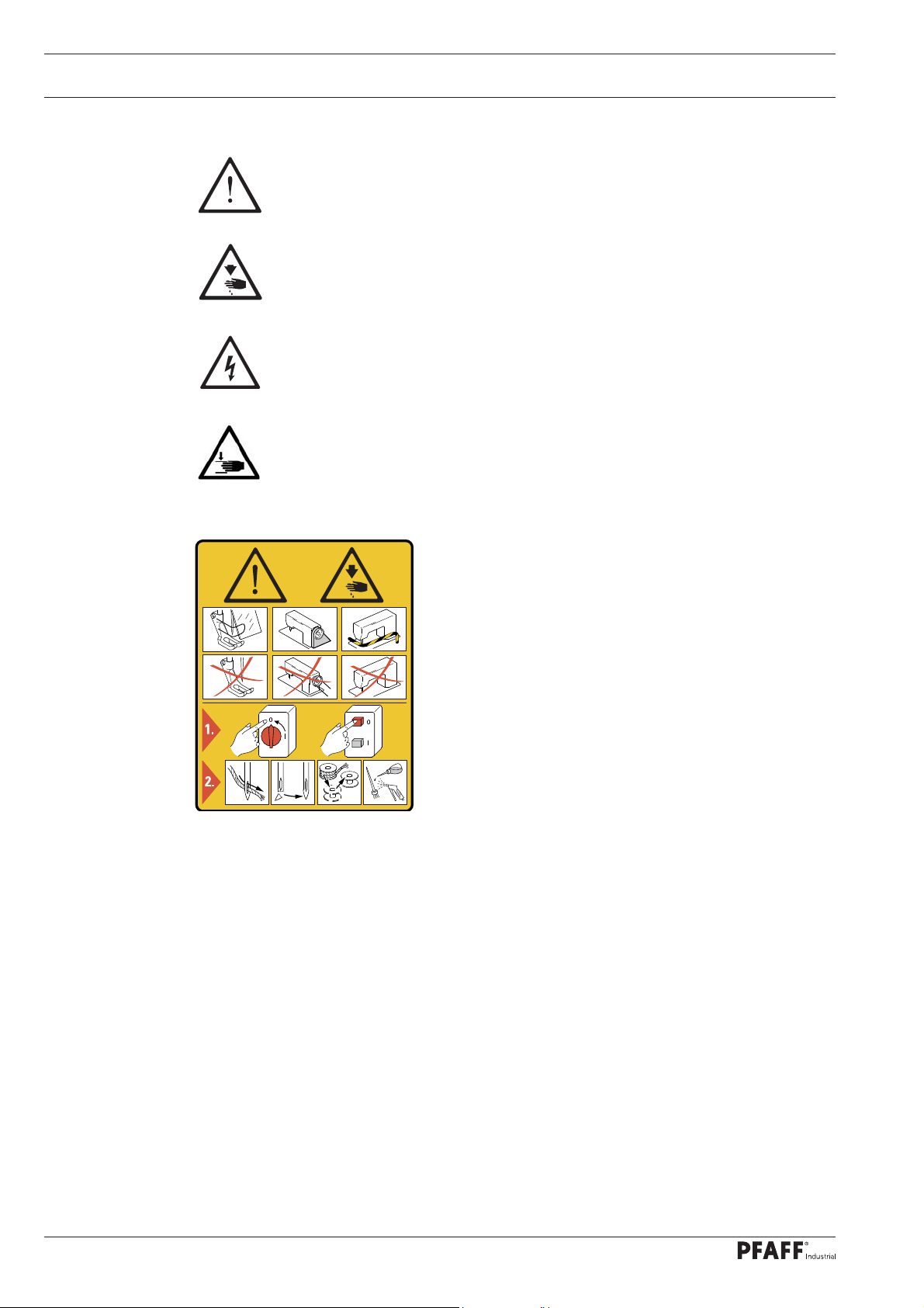
1.03 Safety symbols
Hazard point!
Special points of attention.
Risk of injury to operating personnel or technical staff!
Electric voltage!
Danger to operating personnel or technical staff
Danger of hands being crushed!
Caution!
Do not operate without fi nger guard and safety
covers!
Turn off the main switch before threading, changing the
bobbin or needle, cleaning, etc.!
I
1.04 Special points of attention for the owner-operator
This instruction manual is a part of the machine and must be made available to the
operating personnel at all times. The instruction manual must have been read before the
initial start-up.
The operating personnel and technical staff must be instructed about the machine´s
safety covers and about safe working methods.
The owner-operator may only operate the machine in a fl awless condition.
The owner-operator must ensure that no safety covers are removed or disabled.
The owner-operator must ensure that only authorised persons work on the machine.
Additional information can be requested from the responsible sales centre.
6
Page 7

Safety
1.05 Operating personnel and technical staff
.05.01 Operating personnel
1
Operating personnel are persons responsible for setting up, operating and cleaning the
machine and for fault clearance in the sewing area.
The operating personnel are obligated to comply with the following points:
The safety instructions provided in the instruction manual must be followed for all work!
Any work method jeopardising machine safety must be refrained from!
Tight-fi tting clothing must be worn. The wearing of jewellery such as chains and rings is
prohibited!
Care must be taken to ensure that no unauthorised persons are located in the machine´s
hazard zone!
Any changes occurring on the machine which impair its safety must be reported to the
owner-operator immediately!
1.05.02 Technical staff
Technical staff are persons with technical training in electricity/electronics and mechanics.
They are responsible for lubricating, servicing, repairing and adjusting the machine.
The technical staff are obligated to comply with the following points:
The safety instructions provided in the instruction manual must be followed for all work!
Turn off the main switch before starting any adjustment or repair work and secure it
against reactivation!
Working on live parts and equipment is prohibited!
Exceptions are regulated by the EN 50110 standards.
Unless otherwise stated, the machine must be isolated from the power supply and
pneumatic supplies before any servicing work or repairs are performed!
Exceptions are permitted solely for function tests.
Reattach the safety covers following repair and maintenance work!
7
Page 8
Safety
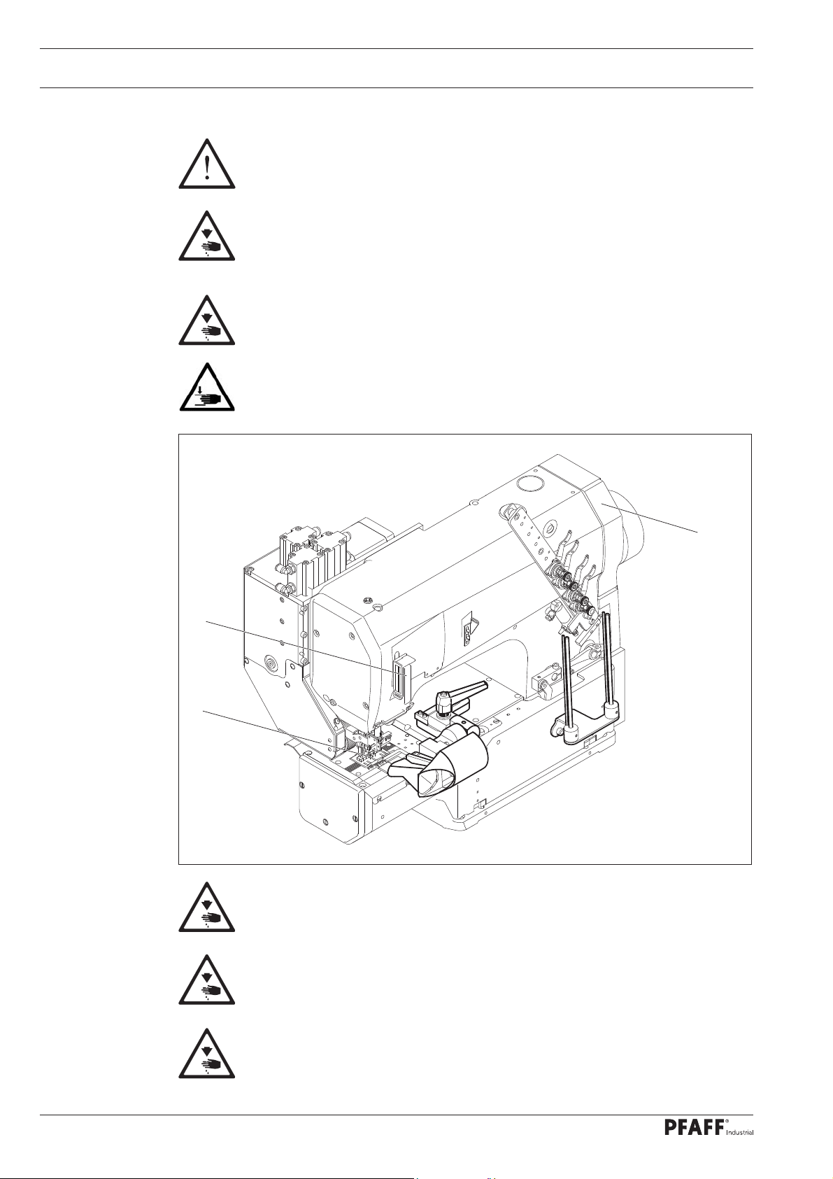
1.06 Danger warnings
A work area of 1 m must be kept around the machine during operation to
ensure unobstructed access at all times.
Do not reach into the needle range during the sewing operation!
Risk of injury from the needle!
Do not allow any objects to be placed on the table during the adjustment work!
The objects could become jammed or be slung away!
Risk of injury from parts fl ying around!
Danger of hands being crushed!
2
1
Fig. 1 - 01
3
Do not operate the machine without the fi nger guard 1!
Risk of injury from the needle!
Do not operate the machine without the take-up lever guard 2!
Risk of injury due to movement of the take-up lever!
Do not operate the machine without the belt guard 3!
Risk of injury due to the rotating driving belt!
8
Page 9

2 Proper Use
The PFAFF 3819 is a sewing machine for effi ciently sewing on trouser waistbands.
Proper Use
Any usage not approved by the manufacturer is deemed misuse! The
manufacturer shall assume no liability for damage caused by misuse!
Proper use also includes compliance with the operating, maintenance,
adjustment and repair measures specifi ed by the manufacturer!
9
Page 10

Technical Data
3 Technical Data
3.01 PFAFF 3819
Stitch type: ....................................................................................................... 401 (chainstitch)
Design B: ......................................................... for the machining of medium-weight materials
Design C: ...........................................................for the machining of medium-heavy materials
Needle thickness: ........................................................................................................ 80 – 140
Needle system: ................................................................................................................. 62-57
Speed max.: ................................................................................................. 4000 stitches/min.
Stitch length max: ..........................................................................................................4.5 mm
Noise data:
Noise emission level at workplace with a sewing speed of n = 2400 min-1: .....LpA = 75 dB(A)
(Noise measurement in accordance with DIN 45 635-48-A-1,ISO 11204, ISO 3744,
ISO 4871)
Motor data: ................................................................................. see motor instruction manual
Air consumption per switching cycle: ...........................................................................0.146 Nl
Net weight of sewing head with stand: ............................................................. approx. 128 kg
Gross weight of sewing head with stand: ..........................................................approx. 258 kg
Subject to alterations
KpA = 2.5 dB
10
Page 11

Disposal of the Machine
4 Disposal of the Machine
It is up to the customer to dispose of the machine properly.
The materials used for the machine include steel, aluminium, brass and various plastics.
The electrical equipment consists of plastics and copper.
The machine must be disposed of in accordance with the locally valid environmental
protection regulations, with a specialised company being contracted if necessary.
Please ensure that parts coated with lubricants are disposed of separately in
accordance with the locally valid environmental protection regulations!
11
Page 12

Transport, Packaging and Storage
5 Transport, Packaging and Storage
.01 Transport to the customer´s premises
5
All machines are completely packed for delivery.
5.02 Transport within the customer´s premises
The manufacturer assumes no liability for transport within the customer´s premises or to
the individual usage sites. Please ensure that the machines are only transported in a vertical
position.
5.03 Disposal of the packaging materials
The packaging materials of these machines consists of paper, cardboard and VCI fl eece. It is
up to the customer to dispose of the packaging properly.
5.04 Storage
The machine can be stored for up to 6 months when not in use. It must then be protected
from dirt and moisture. For longer storage periods, the machine´s single components,
especially its sliding surfaces, must be protected against corrosion, e.g. by an oil fi lm.
12
Page 13

Work Symbols
6 Work Symbols
Activities to be performed or important information in this instruction manual are
emphasised by symbols. The symbols used have the following meaning:
Note, information
Cleaning, care
Lubrication
Maintenance, repairs, adjustment, service work
(only to be carried out by technical staff)
13
Page 14
Operating Controls
7 Operating Controls
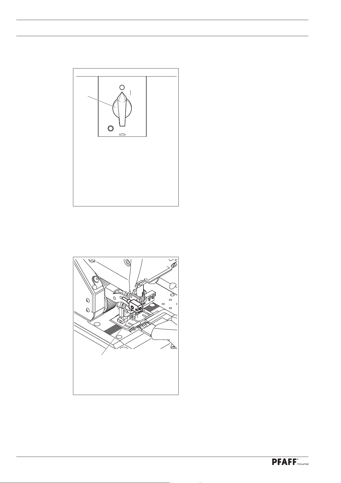
.01 Main switch
7
1
Turning the main switch 1 switches the
machine on and off.
Fig. 7 - 01
7.02 Light barrier
1
The LED in the light barrier 1 indicates
the following status:
– LED lights up green = Reception indica-
tor (If there is no sewing material below
it).
– LED fl ashes green or yellow = Setting
aid/soiling indicator.
– LED lights up yellow = Output indicator
(If there is sewing material below it).
14
Fig. 7 - 02
Page 15
Operating Controls
7.03 Treadle
With the main switch turned on:
+1
Fig. 7 - 03
0
-1
0 = Neutral position
+1 = Manual sewing or
start sewing cycle
-1 = Raise sewing foot and
top needle bar position
15
Page 16
Operating Controls
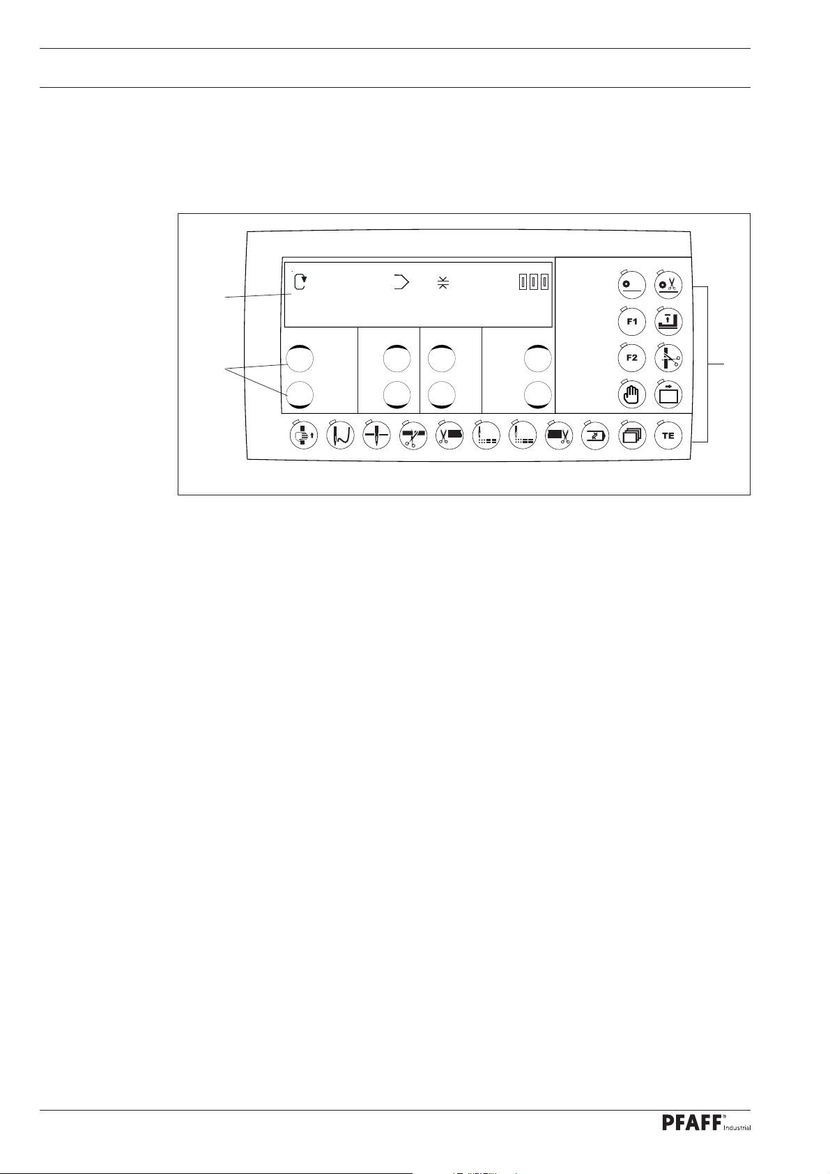
7.04 Control panel
The control panel is used to display and access machine functions for set-up
and sewing, to enter parameter values and to read error messages and service settings.
1
3500 1 3,5 2000
2
0
0
0
Fig. 7 - 04
The control panel has the following operating and display controls:
The display 1 comprises a two-line alphanumerical LCD display with 16 characters per
line and is used to display corresponding information and selection parameters.
The plus/minus keys 2 are used for selecting or altering the functions and parameters
shown on the display.
The function keys 3 are used for turning the corresponding function on and off.
Switched-on functions are each indicated by the lit LED.
3
16
Page 17

Operating Controls
7.04.01 Symbols on the display
In addition to clear texts and set values, the following symbols appear on the display:
The symbols exclusively appear in programmed sewing, see Chapter 10.02 Programmed
sewing.
Symbol Function
Current program number
Piece counter
Speed
Stitch length
SD memory card
Machine memory
7.04.02 Plus/minus keys
The corresponding set values are selected and altered using the appropriate plus-
minus keys. At the same time the set value shown above is changed slowly at fi rst by
pressing and holding the corresponding plus or minus key. If the key is held pressed for
longer, the set value changes more quickly.
3500 1 3,5 2000
Fig. 7 - 05
0
0
0
Plus/minus keys
The displayed values can be increased or decreased using the respective key on the display.
17
Page 18

Operating Controls
7.04.03 Function keys
If a function is on, this is always indicated by the correspondingly lit LED. Detailed explana-
tion of functions:
Thread tape
The sewing drive moves to the top position, the presser foot and both pullers are raised
so that the tape can be threaded in the machine.
This key corresponds to number 1 when entering the code number.
Thread the thread
The sewing drive moves to the top position, the presser foot and both pullers are not
raised so that the needle can be threaded with the sewing thread.
This key corresponds to number 2 when entering the code number.
Position needle downwards
The sewing drive moves to the bottom position.
This key corresponds to number 3 when entering the code number.
Tape cutter on/off
This key corresponds to number 4 when entering the code number.
Tape cutter at seam start on/off
This key corresponds to number 5 when entering the code number.
Skip stitch system at seam start on/off
This key corresponds to number 6 when entering the code number.
Skip stitch system at seam end on/off
This key corresponds to number 7 when entering the code number.
Tape cutter at seam end on/off
This key corresponds to number 8 when entering the code number.
Program
This key is used to execute the menu navigation to create and change the sewing programs. This key corresponds to number 9 when entering the code number.
18
Scroll
If this key is pressed, the input menus on the display are scrolled through.
TE key
If this key is pressed, the machine changes from sewing mode to stitch input mode.
Page 19

Operating Controls
0
0
0
Piece counter
This key is used to set the piece counter to zero.
Coded via parameters 811 and 812.
Puller on/off
Cutting puller on/off
Free
Raise/lower presser foot
This is raised if the presser foot is lowered and lowered if the presser foot is raised.
Coded via parameter 813.
Free.
Free sewing
You can sew with treadle control and the machine does not react to a photo cell.
This key corresponds to number 0 when entering the code number.
19
Page 20

Set-up and Initial Commissioning
8 Set-up and Initial Commissioning
The machine may only be set up and started up by qualifi ed personnel! All of
the relevant safety regulations must always be complied with in this process!
Adequate stability of the stand must be guaranteed, even during the sewing
operations.
8.01 Set-up
Suitable electrical and pneumatic supply connections must be provided at the erection site,
see Chapter 3 Technical Data.
The erection site must have a fi rm and level subsurface and adequate lighting.
The table top is lowered for packaging purposes.
The adjustment of the table height is described below.
8.01.01 Setting the table height
1
Fig. 8 - 01
Loosen the screws 1.
Move the table top to the desired working height by pulling it out and pushing it in and
align the table top horizontally.
Adjust the stand on both sides evenly to prevent it tilting.
Firmly tighten the screws 1.
20
Page 21

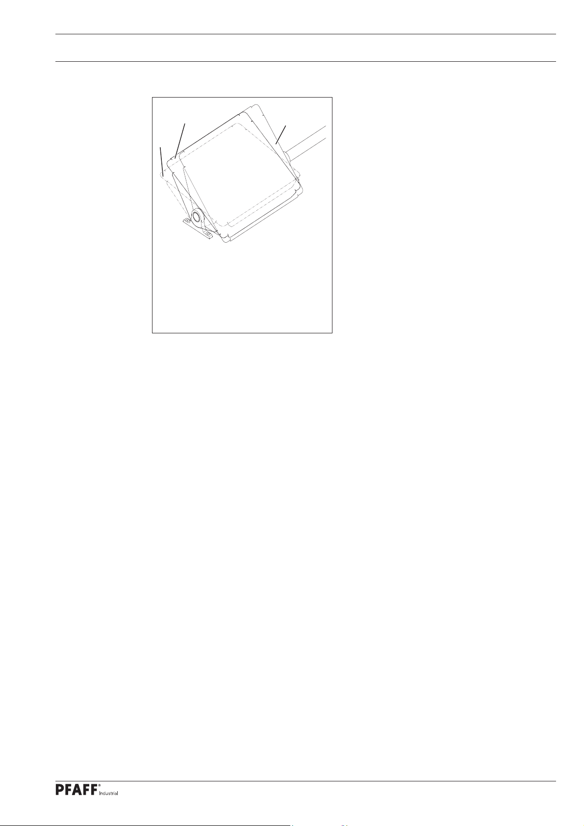
8.01.02 Mounting the reel stand
Fig. 8 - 02
Set-up and Initial Commissioning
Assemble the reel stand as shown in
Fig. 8 - 02.
Then insert the stand into the hole in the
table top and secure it with the enclosed
nuts.
21
Page 22

Set-up and Initial Commissioning
8.02 Connecting the plug-in connections and ground cable
ACHTUNG
ATTENTION
Vertauschungsgefahr
Danger of exchange
SSI
Sollwertgeber
X1/B
X11/B
Ausgänge
Eingänge
X13
X5
RS 232/1
X1/A
CAN-BUS
X11/A
X15
Fadenwächter
Motor
X8
1
E
3
5
4
D
D
2
SM2
X4/A
X3
B
SM1
X4/B
Fig. 8 - 03
Insert all plugs on the control box 2 in accordance with their designation.
Insert the "motor" into the bushing X 3 and the bushing X 8.
Caution!
Plugging in the connector incorrectly can damage the control unit!
Attach the following ground cables in order to discharge static electricity:
Securely attach the ground cable from the sewing head 1 to ground point A.
Securely attach the ground cable from the control point 8 to ground point B.
Securely attach the ground cable from the main switch 3 to ground point C.
Securely attach the ground cable from the stand 4 to ground point D
C
B
A
22
Securely attach the ground cable 5 from the motor to ground point E
Page 23

8.03 Initial start-up
Set-up and Initial Commissioning
Inspect the machine and in particular the
electric lines and pneumatic connecting
hoses for possible damage.
Remove the stopper 1 from the oil tank
2
1
2. The stopper serves solely for transit
support and may not be used during the
sewing operations.
Clean the machine thoroughly
and then oil it, see Chapter 10
Maintenance and Care.
Have technical staff check whether the
machine´s motor may be operated at the
existing mains voltage.
Fig. 8 - 04
Never operate the machine if there are any differences.
Before the initial commissioning, have technical staff verify
that parameter 201 (machine class) is set to "1".
The machine must only be connected to a grounded socket!
Connect the machine to the compressed air system. The manometer should display
a pressure of around 6 bar. Set this value if required
(see Chapter 10.04 Checking / setting the air pressure).
8.04 Switching the machine on/off
Switch the machine on, see Section 7.01 Main switch.
23
Page 24

Set-up
9 Set-up
9.01 Inserting the needle
Observe and comply with all regulations and instructions in this instruction
manual.
Pay particular attention to all safety regulations!
All set-up work may only be carried out by appropriately instructed personnel.
Disconnect the machine from the electricity mains for all set-up work by
operating the main switch or by removing the mains plug!
Switch off the machine!
Risk of injury due to accidental
machine start-up!
Only use needles of the system
intended for the machine, see
Chapter 3 Technical Data!
2
Fig. 9 - 01
Bring the needle bar to the top position
1
1
2
and loosen the screws 1.
Insert the needles 2 up to the stop (while
doing so, the long needle groove must
point to the right).
Tighten the screws 1.
24
Page 25

Set-up
9.02 Threading the needle / adjusting the needle thread
1
Fig. 9 - 02
Switch off the machine!
Risk of injury due to accidental machine start-up!
Thread the needle as shown in Fig. 9-02.
Adjust the needle thread tension by turning the knurled thumb screw 1.
25
Page 26

Set-up
9.03 Threading the looper thread / adjusting the looper thread
3
26
4
Fig. 9 - 03
Switch off the machine!
Risk of injury due to accidental machine start-up!
Open the hook room cover and side cover.
Slide the lever 4 to the left; this unlocks the hook bracket and it can be swivelled out.
Thread the looper thread as shown in Fig. 9-03.
Use tweezers to thread in the thread on the hook 2.
Slide the lever 4 to the left, swivel the hook bracket back in until it engages.
Adjust the looper thread tension by turning the knurled thumb screw 3.
2
Page 27

Set-up
9.04 Fitting the tape reel
Fig. 9 - 04
1
3
Fit the tape reel 1 to the tape reel bracket
2 as shown in 9 - 04.
Please note the unwinding direction:
Tape discharge points towards the
operator.
Cut the beginning of the tape 3 sharply.
2
9.05 Threading the tape into the pleating attachment
Feed the tape through the tape smoother
1.
Insert the tape tip 2 into the pleating
attachment 3 and slide the tape
completely through the pleating
attachment 3 with the aid of scissors.
Fold the tape in the pleating attachment
3 and feed it to the sewing position
2
1
3
Fig. 9 - 05
27
Page 28

Production
10 Production
3500 1 3,5 2000
0
0
0
Fig. 10 - 01
The following appear on the display (from the left):
max. speed (e.g. 3500 revolutions per minute), it can be changed using the correspond-
ing plus/minus key. Coded via parameter 809.
Program number (1 – 99).
Stitch length (e.g. 3.5 mm), it can be changed using the corresponding plus/minus key.
The electronically set stitch length here must be identical to the mechanically set stitch
length on the sewing head. See the "Stitch length" chapter in the adjustment manual to
set the stitch length.
Coded via parameter 810.
Piece counter (e.g. 2000).
The function of the other keys is explained in the "Operating Controls" chapter.
28
Page 29

Production
10.01 Sewing – automatic mode
The following work steps assume that the sewing preparations listed in the
"Set-up" chapter have been carried out thoroughly and the machine has been
programmed according to the order.
Turn on the machine at the main switch and wait for it to be ready for operation.
Press the presser foot key and raise the presser foot.
Place the cut-to-size trouser piece under the raised presser foot directly in front of the
needle (attenuated "skip stitch" photo cell).
The cut-to-size piece must always be placed in the same position when the machine is at
a standstill.
Press the presser foot key and lower the presser foot.
The presser foot automatically lowers when you press the treadle and the machine sews
at a fi xed speed (set in P08) and possibly with the skip stitch system switched on until
the start cut is made ("Tape cutter" photo cell and the clearance programmed in P01).
Switch on the skip stitch system after reaching the appropriate clearance (P02).
After cutting the tape, sew with treadle control until the "Skip stitch" photo cell light up
again and the skip stitch system switches on after reaching the clearance in P03.
Once the "Tape cutter" photo cell lights up, the machine continues to sew at a fi xed
speed (P08) until the fi nal cut clearance (P04) is reached and the fi nal cut is made.
Now stop the machine with the needle down and raise the presser foot.
The next piece can be sewn once the treadle is in the neutral position.
The following keys are switched on in automatic mode, see Fig. 10-02
3500 1 3,5 2000
0
0
0
Fig. 10 - 02
29
Page 30

Production
10.02 Sewing – manual mode
The following work steps assume that the sewing preparations listed in the
"Set-up" chapter have been carried out thoroughly.
Turn on the machine at the main switch and wait for it to be ready for operation.
Press the "Insert tape" key. The needle and puller move to the top dead centre position.
Feed the tape manually to below the puller rollers.
Press the "Insert tape" key again. The needle and puller move to the working position.
Press the "Free sewing" key.
Press the "Tape cutter tape end" key and trim the tape.
Now stop the machine with the needle down and raise the presser foot.
The next piece can be sewn once the treadle is in the neutral position.
30
Page 31

Production
10.03 Input mode
Select the function group
No
500
0
0
0
Fig. 10 - 03
The desired function group must be selected using the allocated plus/minus key after
changing to input mode.
Select the function group or function with the corresponding plus/minus key. The upper key
is + and the lower key is -.
The selected function group is taken over by pressing the plus/minus key under the Enter
symbol and the machine jumps to the "Enter parameter" status after entering the code. This
display does not appear if the access code has already been entered or the function group is
not code protected.
If the TE key is pressed, the machine changes to production mode (LED off).
31
Page 32

Production
The following function groups are available:
Group Function Access rights (factory setting)
100 Operator level free
200 Mechanic level coded
300 Sewing drive positions coded
400 Times coded
500 Counter and speeds coded
600 Service coded
700 Sewing motor coded
800 Access rights coded
Access rights for the individual function groups and for the functions accessible via the keys
can be changed in the function group 800. The access code for coded functions can also be
changed (status on delivery: 3819). Coded functions can only be accessed after entering the
code. Specifi c keys as interpreted as numeric keys for input purposes (see the "Operating
Controls" chapter).
32
Page 33

Production
10.04 Input mode
Enter parameters
No
403
Fig. 10 - 04
VAL
0,03
0
0
0
The display shows the selected parameter number on the left and the associated parameter
value further to the right. Parameter 403, the tape cutter switch-on time, has been selected
in the example above. The displayed parameter value is 0.03 s.
The values above can be changed using the plus/minus keys. The parameter values are
taken over by advancing to another parameter number.
If the TE key is pressed, the values are also taken over and the machine switches to sewing
mode.
33
Page 34

Production
10.05 Programming
Change from sewing mode to programming mode
Select the program number
P
1
0
0
0
Fig. 10 - 05
The desired function group must be selected using the allocated plus/minus key after chang-
ing to programming mode.
Select the program number with the corresponding plus/minus key. The upper key is + and
the lower key is -.
The selected function group is taken over by pressing the plus/minus key under the Enter
symbol and the machine switches to enter the 8 program parameters (P01 – P08).
The entered values are taken over by pressing the "Program" key and the machine switches
back to the initial status of input mode.
The entered values are taken over by pressing the "Sew/Enter" key and the machine switch-
es to input mode.
34
Page 35

Production
10.07 Programming
Control panel display in programming mode
No
VAL
4000P01
0
0
0
Fig. 10 - 06
The display shows the selected programmable parameter number (P01) on the left and the
associated values of the trouser waistband further to the right.
Example:
The maximum program speed is limited to 4000 rpm.
The programmable parameter numbers (P01, P02, ..., P08) can be changed with the
corresponding plus/minus key.
The entered values are taken over by pressing the "Sew/Enter" key and the machine
switches to input mode.
The entered values are taken over by pressing the "Program" key and the machine switches
back to the initial status of input mode.
35
Page 36

Production
10.08 Programming a trouser waistband
Parameter number Function
P01 Maximum program speed
P02 Clearance to start cut in mm
P03 Length of fi rst skip stitch after start of seam at seam
start in mm
P04 Start clearance of fi nal skip stitches in mm
P05 Clearance of fi nal cut at seam end in mm
P06 Length after which the cutting puller moves down at
seam start in mm
P07 Length for which the cutting puller stays down after
the start cut in mm
P08 Constant speed during the tape cutting
36
Fig. 10 - 07
Page 37

Production
10.09 Parameter list
Function group 100: Operator level
101 Display software version (0441/xxx)
102 Display motor control software version
103 Key beeper (I = OFF, II = ON)
104 Thread monitor, left (I = OFF, II = ON)
105 Thread monitor, right (I = OFF, II = ON)
106 Display serial number of machine
Function group 200: Mechanic level
201 Subclass 1: 3819
202 Puller acceleration (200; 50 – 999)
203 Puller braking (250; 50 – 999)
204 Maximum stitch length when sewing in 1/10 mm
(40, 20 –80)
205 Switching frequency from fi ne step to full step
(375; 100 – 2000)
Function group 300: Positions
301 Reference position (needle at top edge of needle plate)
302 Position of cover-thread carrier t.d.c. (153, 0 – 191)
303 Position of needle at bottom position (81, 0 – 191)
Function group 400: Times (0.01 – 2.00 s)
401 Delay time before raising presser foot (0.01 s)
402 Start time after lowering presser foot (0.02 s)
403 Tape cutter switch-on time (0.10 s)
404 Tape cutter travel time (0.03 s)
405 Needle thread monitor hide stitches
(option) 3-9 stitches
406 Bobbin thread monitor hide stitches
(option) 3-9 stitches
Function group 500: Counter, speeds and clearances
501 Soft start stitches (0; 0-15) soft start speed
(1500; 0 – 4500 rpm)
502 Needle cooling start speed (200; 100 – 4500)
503 Clearance of skip stitch light barrier to needle in mm
(30; 0 – 999)
504 Clearance of cutting light barrier to knife in mm
(38; 0 – 999)
37
Page 38

Production
Function group 600: Service
601 Move puller stepping motor
602 Inputs: 0123456789ABCDEF
0: free (E1 – X5.1)
1: free (E2 – X5.2)
2: free (E3 – X5.3)
3: free (E4 – X5.4)
4: free (E5 – X5.5)
5: free (E6 – X5.14)
6: free (E7 – X5.15)
7: free (E8 – X5.16)
8: free (E9 – X5.9)
9: free (E10 – X5.10)
A: free (E11 – X5:11)
B: Needle thread monitor, left (E12 – X5.12)
C: Bobbin thread monitor, right (E13 – X5.13)
D: Skip stitch light barrier (E14 – X5.8)
E: Tape cutter light barrier (E15 – X5.6)
F: free (E16 – X5.7)
603 Outputs:
1: Presser foot (X13.1 and X13.2) (1: up, 0: down)
2: Tape cutter (X13.3 and X13.4) (1: down, 0: up)
3: Needle cooling (X13.5)
4: Thread tension (X13.6) (1: open, 0: close)
5: Skip stitch generation (X13.7) (1: on, 0: off)
6: Raise transport puller (X13.8) (1: up, 0: down)
7: Raise cutting puller (X13.9) (1: up, 0: down)
8: free (X13.10)
9: free (X13.11)
10: free (X13.12)
11: free (X13.13)
12: free (X13.25)
13: free (X13.24)
14: free (X13.16)
15: Sewing motor running (X5.17) ( 1: running, 0: at a
standstill)
16: free (X5.18)
38
Page 39

Production
604 Run cold start
605 Display treadle values
Function group 700: Sewing motor
701 P-section speed regulator (10)
702 I-section speed regulator (50)
703 P-section position controller (20)
704 D-section position controller (30)
705 Time for position controller (25)
706 P-section position controller for rest brake (25)
707 D-section position controller for rest brake (15)
708 Maximum torque for rest brake (0)
709 Minimum machine speed (6)
710 Maximum machine speed (4500)
711 Maximum motor speed (68)
712 Positioning speed (25)
713 Acceleration ramp (35)
714 Braking ramp (30)
715 Reference position (43)
716 Dead man time (40)
717 Motor starting current (7)
718 Anti-rank fi lter (3)
719 Rotation direction assignment (1)
720 Positioning technique
(1 – time-optimised; 2 – path-optimised)
Function group 800: Access rights
801 Access rights for function group 100*
802 Access rights for function group 200*
803 Access rights for function group 300*
804 Access rights for function group 400*
805 Access rights for function group 500*
806 Access rights for function group 600*
807 Access rights for function group 700*
808 Access rights for function group 800*
809 Access rights for programming*
810 Access rights for stitch length keys*
811 Access rights for maximum key speed*
812 Enter access code (in status on delivery: 3819)
* 0 – free, 1 – blocked with a code
39
Page 40

Production
10.10 Program management
The program management menu opens after pressing the "Scroll" key in input mode (LED in
the key lights up).
Standard SD cards with a maximum capacity of 2 GB can be inserted in the control panel
Bdf-S3. The 3819 stores its data in the subdirectory \P3819. Programs 1 – 99 are stored in
fi les 01 – 99 and the machine data is stored in the MD fi le. If the SD card is to be formatted
with the PC, it must be formatted in the FAT16 format.
You can also format the SD card with the formatting function on the 3819. All actions are
started with the +/- key under the Enter symbol. Values can be changed under the respec-
tive value using the +/- keys.
The functions are:
Display the machine directory
Display the SD card directory
Copy program(s) to the SD card
Copy program(s) from the SD card
Delete program(s) in the machine memory
Delete program(s) on the SD card
Format the SD card
10.10.01 Inserting and removing the SD memory card
Inserting the SD card
Open the cover 1.
Insert the SD card 2 into the card slot
with the label facing forwards.
Close the cover 1 again.
Removing the SD card
Open the cover 1.
Press gently on the SD card 2 –
the SD card will be ejected.
Close the cover 1 again.
The SD card must be kept for future
boot processes.
40
Fig. 10 - 08
The SD card is not a default
confi guration.
Only use FAT16 format memory cards.
Adjusting the slide 3 makes it possible to activate (LOCK) or deactivate the
write protection function on the SD card. The write protection function must be
deactivated to store, edit or delete data on the SD card.
Page 41

Production
10.10.02 Displaying the machine directory
DIR
0
0
0
Fig. 10 - 09
The contents of the machine memory are displayed after pressing the +/- key under the En-
ter symbol .
DIR
01 02 40
Fig. 10 - 010
42 END
0
0
0
You can scroll through within the display by pressing the right +/- keys. You can switch to
the next/previous menu item by pressing the left +/- keys.
41
Page 42

Production
10.10.03 Displaying the SD card directory
Fig. 10 - 11
DIR
0
0
0
The contents of the SD card are displayed after pressing the +/- key under the Enter symbol
.
DIR
01
Fig. 10 - 12
02 40 END
0
0
0
42
You can scroll through within the display by pressing the right +/- keys. You can switch to
the next/previous menu item by pressing the left +/- keys.
Page 43

Production
10.10.04 Copying program(s) to the SD card
>>COPY
0
0
0
Fig. 10 - 13
The machine switches from the machine memory to the SD card to enter the copy function
after pressing the +/- key under the Enter symbol .
>>
COPY 01 02
0
0
0
Fig. 10 - 14
The program numbers of the program that you want to copy in the machine memory and
on the SD card can be selected with the +/- buttons under the values.
The MD machine data can only be copied to the machine data fi le.
If the complete machine contents
ALL
are selected, all programs are copied to the SD card.
If a program is already present on the SD card, a prompt for confi rmation will be displayed.
The right + key confi rms that the data will be overwritten. The right – key cancels the over-
writing process.
43
Page 44

Production
10.10.05 Copying program(s) from the SD card.
Fig. 10 - 15
<<COPY
0
0
0
The machine switches from the SD card to the machine memory to enter the copy function
after pressing the +/- key under the Enter symbol .
<<
COPY ALL ALL
0
0
0
Fig. 10 - 16
44
The program numbers of the program that you want to copy in the machine memory
and on the SD card can be selected with the +/- keys under the values.
The MD machine data can only be copied to the machine data fi le.
If the complete machine contents
ALL
are selected, all programs are copied to the ma-
chine memory.
If a program is already present in the machine memory, a prompt for confi rmation will be
displayed. The right + key confi rms that the data will be overwritten. The right – key cancels
the overwriting process.
Page 45

Production
10.10.05 Deleting program(s) in the machine memory
DEL
0
0
0
Fig. 10 - 17
The machine switches to the machine memory to enter the delete function after pressing
the +/- key under the Enter symbol .
DEL 01
0
0
0
Fig. 10 - 18
You can switch to the program number of the program in the machine memory that you
want to delete using the +/- keys.
If the complete machine contents
ALL
are selected, all programs are deleted.
The MD machine data cannot be deleted.
A prompt for confi rmation is displayed before deleting the data. The right + key confi rms
that the data will be overwritten. The right – key cancels the overwriting process.
45
Page 46

Production
10.10.06 Deleting program(s) on the SD card
Fig. 10 - 19
DEL
0
0
0
The machine switches to the machine memory to enter the delete function after pressing
the +/- key under the Enter symbol .
DEL ALL
0
0
0
Fig. 10 - 20
46
You can select the program number of the program on the SD card that you want to de-
lete using the +/- keys under the value.
If the complete machine contents
ALL
are selected, all programs on the SD card are
deleted.
A prompt for confi rmation is displayed before deleting the data. The right + key confi rms
that the data will be overwritten. The right – key cancels the overwriting process.
Page 47

Production
10.10.07 Formatting the SD card
FORMAT ALL
0
0
0
Fig. 10 - 21
The SD card is formatted after pressing the +/- key under the Enter symbol .
A prompt for confi rmation is displayed before the SD card is formatted. The right + key con-
fi rms that the card will be formatted. The right – key cancels the formatting process.
The card will be completely formatted if it cannot be read. All fi les in this directory will be
deleted if it can be read and the directory \P3819 for the 3819 exists.
If the directory \P3819 for the 3819 does not exist, only the directory is created. This is to
ensure that programs from other machines and other fi les are not lost.
47
Page 48

Production
10.10.08 Error messages
Error code Description
Error 1 System error
Error 2 Sewing motor ERROR 2/BB/xxx
BB = 20 Deadman
10 Speed
0B StopX
0A Reset stitch counter
09 Write parameter
05 Position t.d.c. by shortest route
03 Position t.d.c. in reverse
02 Position t.d.c. forwards
30 Timeout for increasing speed
31 Timeout from uncertain positioning
32 Timeout from deadman command
33 Timeout for deleting errors
34 Timeout for emergency stop
35 Timeout for writing parameters
36 Timeout for resetting stitch counter
37 Timeout for stop command after x stitches
38 Timeout for initialisation
xxx = sewing motor control
unit error (see Motor errors)
Error 3 Ramp memory too small
Error 4 free
Error 5 Treadle activated when machine turned on
Error 6 free
Error 7 Stepping motor movement
Error 8 free
Error 9 Needle thread monitor
Error 10 Lower thread monitor
Error 11 Stepping motor step frequency too high
Error 12 free
Error 13 free
Error 14 free
Error 15 free
Error 16 free
39 Establishing contact when turned on
1. Ramp X not ready
2. Ramp Y not ready
3. Time monitoring
48
Page 49

Production
Error 17 free
Error 18 free
Error 19 free
Error 20 free
Error 21 Power supply unit overloaded (24V)
Error 22 Mains voltage
Error 23 Power supply 24V too low
Error 24 free
Error 25 free
Error 26 free
Error 27 1. SD card reader error:
No SD card inserted
2. Incorrect card (does not fi t 3819)
3. Card incorrectly inserted
4. Card is write-protected
5. Data error on SD card
6. Formatting failed
7. File does not fi t 3819
8. Incorrect fi le size
9. Transfer error
10. File could not be deleted
Error 28 free
Error 29 1. CAN error:
Timeout
2. Incorrect answer
4. Lost data
Error 30 free
All error messages are acknowledged with the key. If the key is pressed, the
error is also acknowledged and the machine changes to stitch input mode.
49
Page 50

Production
Motor errors
Error code Description
33 Invalid parameter value
35 Communication error
36 Init. not ready
37 Command overrun
64 Mains off during initialisation
65 Excess current directly after mains on
66 Short circuit
68 Excess current during operation
70 Motor blocked
71 No incremental plug
74 Incremental encoder missing for transmission/
reduction
173 Motor blocked in 1st stitch
175 Internal starting error
222 Dead man monitoring
50
Page 51

Maintenance and Care
11 Maintenance and Care
.01 Maintenance intervals
11
Cleaning the hook area .............................daily, several times during continuous operation
Cleaning the complete machine ............................................................................... weekly
Machine oil level .................................................................................. daily, before start-up
Checking / setting the air pressure ...................................................................... as needed
Cleaning the maintenance unit air fi lter ............................................................... as needed
These maintenance intervals are based on an average running time of a single
shift production shop. Shorter maintenance intervals are recommended for in-
creased running times.
11.02 Cleaning the machine
The required cleaning cycle for the machine depends on the following factors:
Single or multi-shift operation
Dust formation caused by the workpieces
Optimal cleaning instructions can therefore only be determined on a case-by-case basis.
Disconnect the machine from the electricity mains for all cleaning work by
shutting off the main switch or removing the mains plug! Risk of injury due to
accidental machine start-up!
The following tasks are recommended
during a single shift operation to avoid
operational errors:
Open the hook area cover 1.
Daily, clean the hook area 2 more
frequently during continuous operation.
Close the gripper area cover!
Only operate the machine
when the hook room cover is
closed!
Risk of injury due to moving
parts!
2
1
Fig. 11 -01
51
Page 52

Maintenance and Care
11.03 Checking / topping up the oil level of the oil tank for the front parts
2
max.
min.
1
Fig. 11 - 02
Check the oil level before every start-up.
The oil level must not drop below the "min." marking and rise above the "max."
marking.
The oil level must always be visible in the sight glass 1.
Add oil to the container through the hole 2 as needed
Only use oil with a centre viscosity of 22.0 mm2/s at 40 °C and a density of
0.865 g/cm3 at 15 °C.
We recommend PFAFF sewing machine oil part no. 280-1-120 144.
52
Page 53

Maintenance and Care
11.04 Checking / topping up the oil level of the gear mechanism
2
1
Fig. 11 - 03
Switch off the machine!
Risk of injury due to accidental machine start-up!
Open the side cover and check the oil level before every machine start-up.
The oil level must always be visible in the sight glass 1 (if no air bubble is visi-
ble, then the oil level is too high).
Remove the screw 2 as needed and add only enough oil for an air bubble to remain
visible.
Replace the screw 2.
Only use oil with a centre viscosity of 22.0 mm2/s at 40 °C and a density of
0.865 g/cm3 at 15 °C.
We recommend PFAFF sewing machine oil part no. 280-1-120 144.
53
Page 54

Maintenance and Care
11.05 Checking / setting the air pressure
1
Check the air pressure on the manome-
2
ter 1 before every start-up.
The manometer 1 must show a pressure
of 6 bar.
Adjust this value if needed.
Pull up the button 2 for this and turn it
out of position accordingly.
Fig. 11 - 04
11.06 Emptying / cleaning the maintenance unit´s water tank
Switch the machine off.
Detach the compressed air
tube on the maintenance unit.
Empty the water tank
The water tank 1 empties itself automat-
ically after the compressed air tube for
the maintenance unit has been removed.
Clean the fi lter
Unscrew the water tank 1 and
2
take out the fi lter 2.
54
Fig. 11 - 05
Clean the fi lter with compressed air or
isopropyl alcohol, part number
1
95-665 735-91.
Screw in the fi lter 2 and screw on the
water tank 1.
Page 55

Wearing Parts
12 Wearing Parts
This list shows the most important wearing parts.
A detailed parts list for the complete machine can be downloaded at
www.pfaff-industrial.de/de/service-support/downloads/technical.
As an alternative to the Internet download, the parts list can also be requested
as a hard copy under order no. 296-12-19 290.
11-173 174-15
11-108 171-15 (2x)
91-264 154-25 (2x)
11-108 171-15 (2x)
11-174 089-15
11-174 089-15 (4x)
System 62 x 57
11-174 173-25
11-330 082-15 (2x)
91-172 843-05 (2x)
91-100 348-15
95-352 069-25
95-352 068-05
95-352 070-25
11-225 223-25 (4x)
55
Page 56

PFAFF Industriesysteme
und Maschinen GmbH
Hans-Geiger-Str. 12 - IG Nord
D-67661 Kaiserslautern
Telefon: +49 - 6301 3205 - 0
Telefax: +49 - 6301 3205 - 1386
E-mail: info@pfaff-industrial.com
Gedruckt in der BRD / Printed in Germany / Imprimé en la R.F.A. / Impreso en la R.F.A
© PFAFF is the exclusive trademark of VSM Group AB I PFAFF Industriesysteme und Maschinen GmbH is an authorized licensee of the PFAFF trademark.
 Loading...