

Page 1

3811
- 2/45
- 11/43
-11/45
-1 3/45
Instruction manual
● For machines with a thread trimmer use
the Maintenance Manual -900/71 for the
PFAFF 5480.
● Use the motor manufacturer's technical
literature for the motor.
296-12-17 514
Betriebsanleitung engl. 06.97
Page 2
2
Notes on safety
l The machine must only be commissioned in full knowledge of the instruction manual and operated by
persons with appropriate training.
l Before putting into service also read the safety rules and instructions of the motor supplier.
l The machine must be used only for the purpose intended.
Use of the machine without the safety devices is not permitted.
Observe all the relevant safety regulations.
l When gauge parts are exchanged (e.g. needle, presser foot, needle plate, feed dog and bobbin) when
threading, when the workplace is left, and during service work, the machine must be
disconnected from the mains by switching off the master switch or disconnecting the mains plug.
l On mechanically operated clutch motors without start inhibitor it is necessary to wait until the motor
has stopped.
l Daily servicing work must be carried out only by appropriately trained persons.
l Repairs, conversion and special maintenance work must only be carried out by technicians or persons
with appropriate training.
l For service or repair work on pneumatic systems the machine must be disconnected from the compressed
air supply system.
Exceptions to this are only adjustments and function checks made by appropriately trained technicians.
l Work on the electrical equipment must be carried out only by electricians or appropriately trained persons.
l Work on parts and systems under electric current is not permitted, except as specified in regulations
EN 50110.
l Conversions or changes to the machine must be authorized by us made only adherence to all safety
regulations.
l For repairs, only replacement parts approved by us must be used.
l Comissioning of the sewing head is prohibited until such time as the entire sewing unit is found to
comply with EC directives.
Meanings of the symbols:
Danger spot!
Items requiring special attention.
Danger of injury to operative
service staff.
Be sure to observe and adhere to these notes!
Page 3

3
Inhaltsverzeichnis
Notes on safety................................................................................................................ 2
What the symbols mean.................................................................................................. 2
Fields of application.......................................................................................................... 5
1 Technical data .................................................................................................................. 5
2 Operation elements and optical displays.......................................................................... 6
3 Initial check ...................................................................................................................... 8
4 Installing the machine ...................................................................................................... 8
5 Connecting compressed air and electricity ...................................................................... 8
.1 Compressed air................................................................................................................8
.2 Electricity ......................................................................................................................... 8
6 Switching the machine on................................................................................................ 8
7 Switching the machine off ............................................................................................... 8
8 Check ............................................................................................................................. 10
.1 Oil level in the sewing machine ..................................................................................... 10
.2 Direction of rotation ....................................................................................................... 10
9 Inserting the needle ....................................................................................................... 10
10 For your attention before the initial operation ................................................................ 10
11 Needle thread and hook thread...................................................................................... 12
.1 Threading the needle thread .......................................................................................... 12
.2 Adjusting the needle thread tension .............................................................................. 12
.3 Threading the hook thread ............................................................................................. 12
.4 Adjusting the hook thread tension ................................................................................. 12
12 Top feed pressure and presser foot pressure ................................................................ 14
.1 Adjusting the top feed pressure..................................................................................... 14
.2 Adjusting the presser foot pressure............................................................................... 14
13 Adjusting the stitch length ............................................................................................. 14
14 Preparing for adjustments.............................................................................................. 16
15 Needle position in the needle hole................................................................................. 16
.1 Across the sewing direction........................................................................................... 16
.2 With the sewing direction .............................................................................................. 16
16 Preadjusting the needle height....................................................................................... 18
17 Bottom feed settings ..................................................................................................... 20
.1 Zeroing the main feed dog ............................................................................................. 20
.2 Limiting the shortest stitch length to 2 mm................................................................... 20
.3 Main feed and differential feed synchronicity ................................................................ 22
.4 Lateral motion of main and differential feeds................................................................. 24
.5 Lifting motion of main and differential feeds.................................................................. 26
.6 Setting the feed dog ...................................................................................................... 28
18 Top feed settings ........................................................................................................... 30
.1 Synchronicity of top and bottom feeds .......................................................................... 30
.2 Vibrating presser - lifting motion .................................................................................... 32
.3 Vibrating presser - stroke ............................................................................................... 32
.4 Front connecting rod to the top feed drive..................................................................... 34
19 Basic stitch length.......................................................................................................... 36
.1 Adjust basic stitch length to 3 mm ................................................................................ 36
Page 4

4
20 Presser foot settings...................................................................................................... 38
.1 Clearance between presser foot and needle plate......................................................... 38
.2 Presser foot stroke with the automatic presser foot lifter ............................................. 38
.3 Aligning the presser foot ................................................................................................ 40
21 Hook settings.................................................................................................................42
.1 Hook - lateral motion ...................................................................................................... 42
.2 Adjusting the hook height .............................................................................................. 44
.3 Adjusting the hook angle................................................................................................ 46
.4 Hook-to-needle clearance in sewing direction................................................................ 46
.5 Hook-to-needle clearance in hook direction (across the sewing direction)..................... 46
.6 Hook motion .................................................................................................................. 48
.7 Needle height and hook-to-needle clearance ................................................................. 50
22 Rear needle guard.......................................................................................................... 52
.1 Adjusting the height of the rear needle guard ................................................................ 52
.2 Clearance between rear needle guard and needle ......................................................... 52
23 The hook-eccentric guard............................................................................................... 52
24 Front needle guard ......................................................................................................... 54
.1 Adjusting the height ....................................................................................................... 54
.2 Lateral adjustment ......................................................................................................... 54
25 Needle thread puller....................................................................................................... 56
26 Needle thread regulator ................................................................................................. 56
27 Adjustable thread guide ................................................................................................. 56
28 Hook thread regulator .................................................................................................... 58
29 Hook thread controller.................................................................................................... 58
30 Hook thread puller.......................................................................................................... 58
31 Quick adjustment of the differential for altering the gathering intensity ........................ 60
.1 Zeroing the differential quick adjustment ....................................................................... 60
.1.1 Rough adjustment at the Angle transmitter ................................................................... 60
.1.2 Fine adjustment at the poti “0” ..................................................................................... 60
.2 Key allocation for positioning the cam against the actuating lever................................. 62
.2.1 Setting the gathering level of key “1”............................................................................ 62
.2.2 Setting the gathering levels ........................................................................................... 62
32 Edge trimmer................................................................................................................. 64
.1 Trimming motion............................................................................................................ 64
.2 Zero point ....................................................................................................................... 64
.3 Knife height .................................................................................................................... 64
.4 Aligning the upper knife in sewing direction .................................................................. 66
.5 Aligning the upper knife across the sewing direction..................................................... 66
.6 Aligning the stop eccentric............................................................................................. 66
33 Tape brake ..................................................................................................................... 68
.1 Switching on ..................................................................................................................68
.2 Switching off.................................................................................................................. 68
.3 Adjusting the brake intensity.......................................................................................... 68
.4 Pre-tension..................................................................................................................... 68
34 Care and maintenance ................................................................................................... 70
.1 Sewing machine ............................................................................................................ 70
.2 Maintenance unit ........................................................................................................... 70
.3 Lubrication recommendation.......................................................................................... 71
Page 5

5
1 Specifications for the PFAFF 3811-../..
Sewing machine head : for -2/45: .................... 5487/5489-814/01 N
for -11/43 und -11/45:.. 5487/5489-814/01
for -13/45: .................. 5487/5489-814/01-731/12
Stich type : 401
Max. s.p.m. : 3200 min
-1
Basic stitch length : 3 and 4 mm ( -2/45 2,2 mm)
Differential stitch length : 8 mm ( -2/45 6 mm)
Needle system : Leather: 4463KKD
Fabric: 4463-35
Needle size : 80 - 110 depending on material
Trimming margin : (only -13/45) 6mm
Presser foot clearance : 7mm
Sewing motor : QE 6040, Q 31 PLUS, P 40 SE, Q 40 SE
Input rating : 0,8 kW
Power supply : E 230 Volt, 50/60Hz
Working air pressure : 6 bar
Air consumption : ~0,3 - 0,5 Normlitre per work cycle
Work place related emission level : at s.p.m. n=2600min-1: LpA<79 dB(A). Noise level
measurement in accordance with DIN 45635-48-A-1
Dimensions : LxBxH (1250 x 600 x 1700mm; incl. spool holder)
Weight : Net: 140 kg
Subject to alterations Status 06.94
Fields of application
PFAFF 3811-2/45
-11/43
-11/45
Integrated sewing unit for working fullness into a material ply
PFAFF 3811-13/45
Integrated sewing unit for working fullness into a material ply with simultaneous edge
trimming
Page 6
6
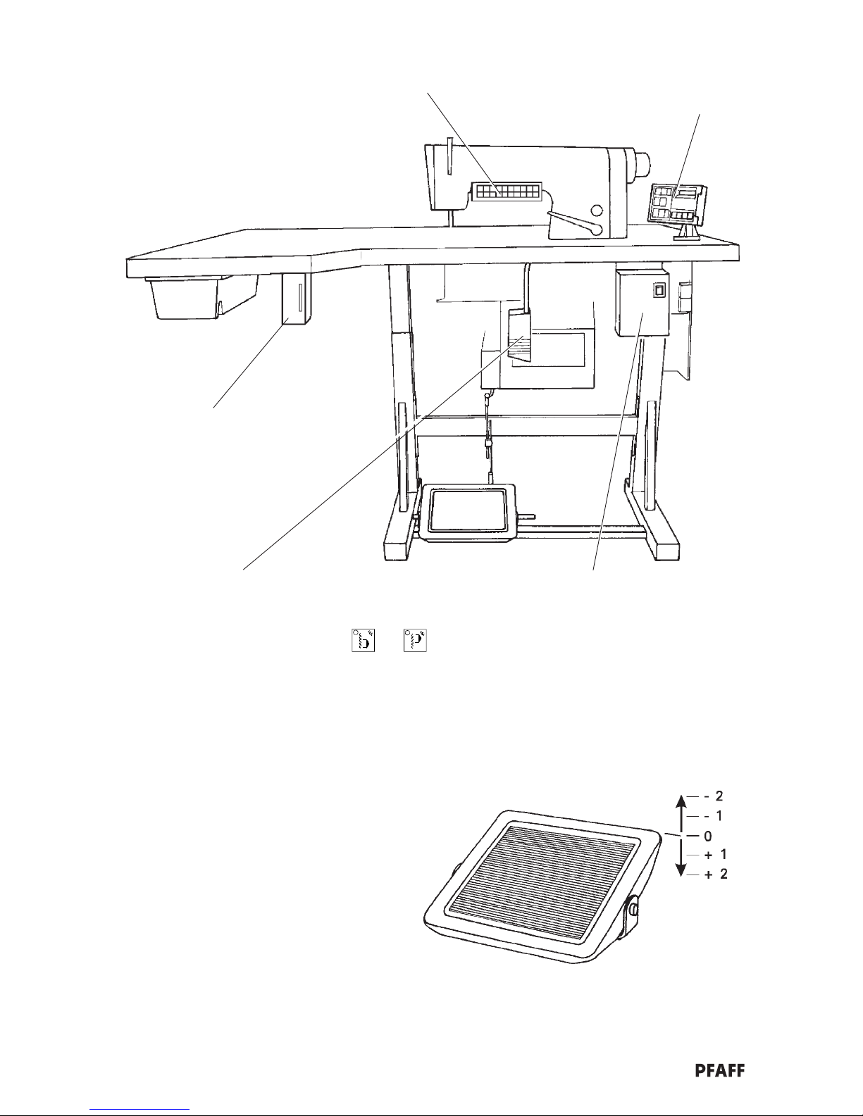
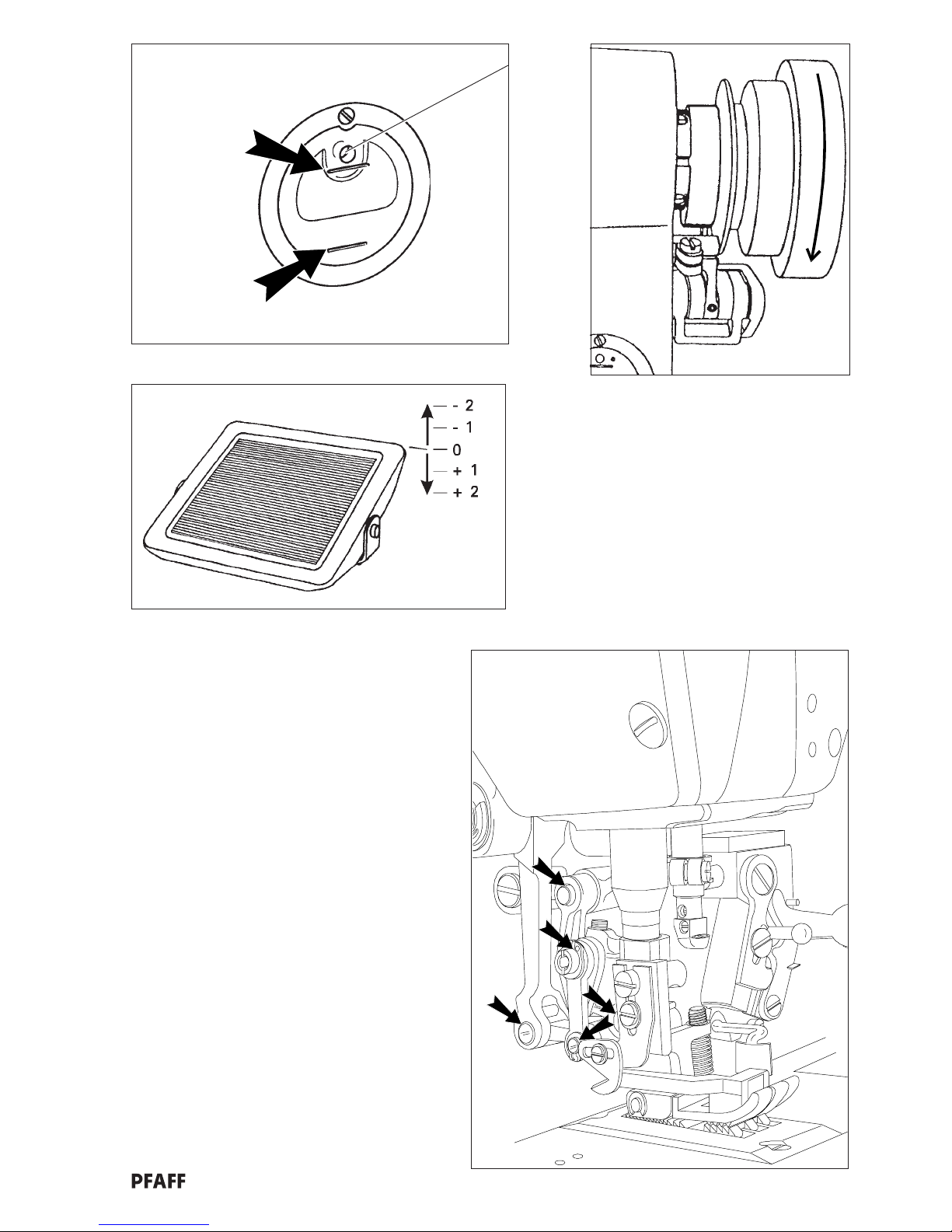
Key panel
Potentiometer 0-15
for adjusting the fullness as
allocated to the numbered keys
Foot pedal
0 = Foot pedal resting position
+ = Foot pedal forwards
+1 = Presser foot down
s
+2 = Sewing
- = Foot pedal reverse
-1 = Presser foot up s, needle position
-2 = Trim thread (optional)
Presserfußposition
s
Bi02-10
On/off switch
For switching the entire
work station on and off. The
version depends on the
motor.
Quick digital motor control panel
(see technical literature from the
motor manufacturer)
Knee lever for fullness
By pressing the knee lever you achieve the following results:
on the -2/45: switching between the two fullness levels which
are set with the keys and
on the -11/43, -11/45, -13/45:
switching between the last value selected with a
numbered key and sewing without fullness.
s
= in accordance with the switch setting on
the motor control panel (see technical
literature from the motor manufacturer)
2 Operation elements and optical displays
Bi02-01
Page 7
7
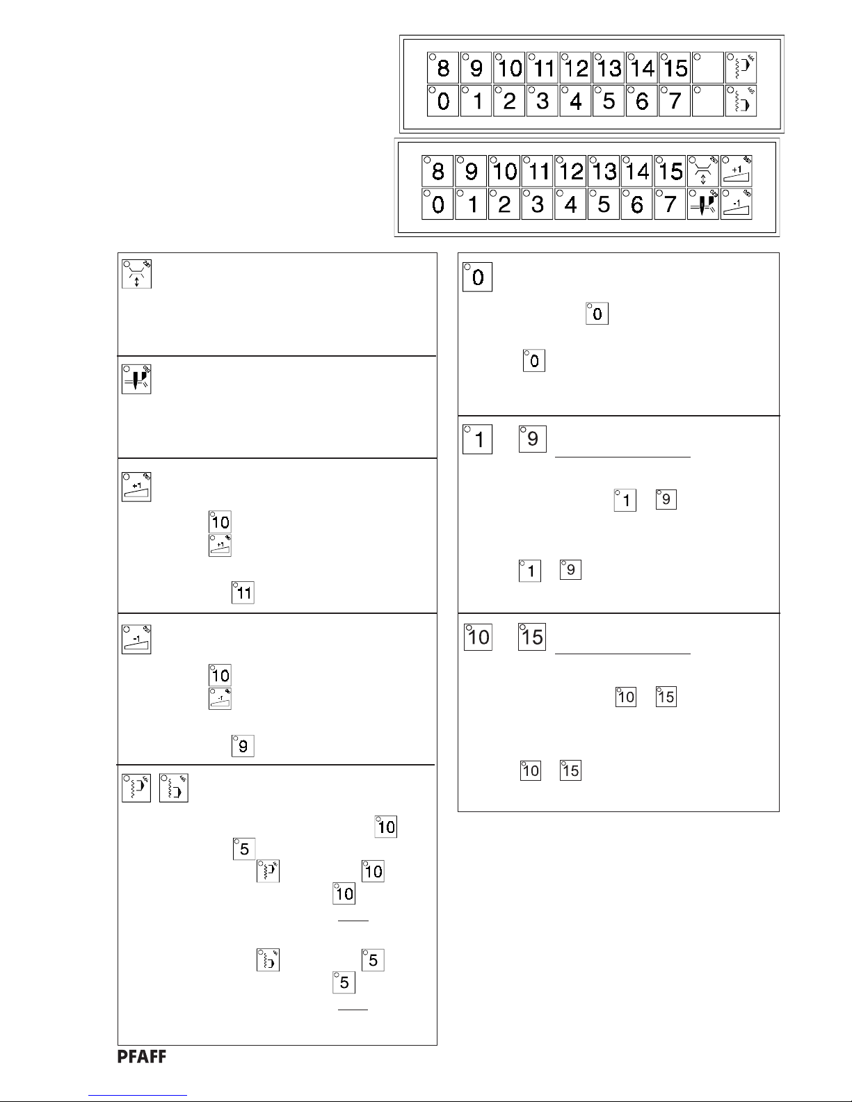
Key panel -2/45
(Key activ = LED on)
Key panel -11/43; -11/45; -13/45
Tape brake on/off (optional)
This key is also on the -11/43, -11/45 and -13/45
even when there is no tape brake installed.
In this case it has no function whatsoever.
The tape brake can be installed at a later date.
Fullness 0
Sewing without fullness
By pressing the
key you switch to
“sewing without fullness”.
The key is activated automatically when
the machine is switched on.
(except on -2/45)
Numbered keys for fullness levels
Basic stitch length: 4 mm
By pressing one of the keys to you switch to the
basic stitch length of 4 mm.
With keys to , the fullness levels set with the
potis “1” to “9” can be called up.
to
Numbered keys for fullness levels
Basic stitch length: 3 mm
By pressing one of the keys
to you switch to the
basic stitch length of 4 mm.
With keys
to , the fullness levels set with the
potis “10” to “15” can be called up.
to
Edge trimmer on/off
(only on -13/45)
This key is also on the other sub-classes but
it is without function.
The edge trimmer cannot be installed later.
for setting 2 fullness levels which can be
switched to and from with the knee lever.
(only -2/45)
Example: if you wish to switch between key
and key .
l Press the key, press the key
- The fullness level of the
key is
now programmed as the
upper
gathering level.
l Press the key, press the key
- The fullness level of the
key is
now programmed as the
lower
gathering level.
for switching from a numbered key to the fullness level of the next lowest numbered key.
Example: the
key is activated (LED on)
the key is pressed
- Machine switches to the fullness level
of key
for switching from a numbered key to the full-ness
level of the next highest numbered key.
Example: the key is activated (LED on)
the key is pressed
- Machine switches to the fullness level
of key
Bi02-02.CDR
Bi02-03.CDR
Page 8

8
3 Initial check
After unpacking the machine and before operating it for the first time, check that it has not
been damaged during transport.
If any damage has occurred, inform the forwarding company and your Pfaff agent immediately.
4 Installing the machine
Place the machine in the desired position on a horizontal surface.
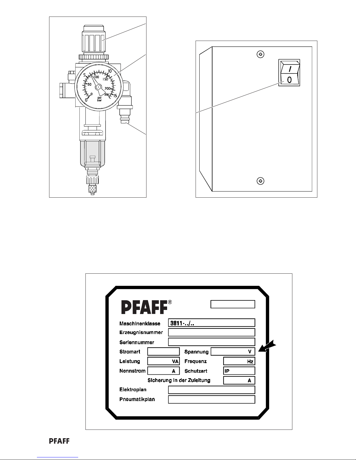
5 Connecting compressed air and electricity
5.1 Compressed air
Connect the compressed air hose (6 mm internal diameter) to coupling 1 (diag. 1).
Minimum pressure in system: 7 bar
Working pressure: 6 bar
Pressure regulation: adjusting knob 2
5.2 Electricity
.1 The admissable working voltage (arrow in fig. 3) is indicated on the specification plate.
.2 Never operate the machine if the supply voltage and the working voltage are not the
same! (circuit diagram!)
.3 Only plug the machine into an earthed power socket.
6 Switching the machine on
.1 Open the air pressure at the main conductor.
.2 Check the working pressure: 6 bar (Manometer 3; fig. 1)
.3 Adjust if necessary (adjustment knob 2).
.4 Switch on the machine (switch 4 to “|”; fig. 2)
Note: Other switch combinations are possible.
E.g. Switch on the machine = Press the “|” key.
7 Switching the machine off
Switch 4 to “O” (fig. 2).
Note: Other switch combinations are possible.
E.g. Switch on the machine = Press the “0” key.
Page 9
9
1
1
2
3
-1/..
Bi34-01.CDR
2
4
3
Bi03-03.CDR
Page 10

10
8 Checks
8.1 Oil level in the sewing machine
When necessary, fill by pouring oil through hole 1 (fig. 1) in the oil-level sight glass.
We recommend Pfaff sewing-machine-oil, article number 280-1-120 or an oil with a
mean viscosity of 22.0 mm2/s at 40°C and a density of 0.865 g/cm3.
8.2 Direction of rotation
Requirement: The handwheel must turn in the direction of the arrow (fig. 2).
.1 Switch on the machine.
.2 Lift the presser foot with the hand lever.
.3 Press the foot pedal lightly (+1) forwards (fig. 3).
.4 If the direction of rotation is wrong, see the technical literature from the motor manufacturer;
parameter 800.
9 Inserting the needle
.1 Switch the machine off (mains switch).
.2 Slide the needle bar into position until it stops (long groove facing the operator).
10 For your attention before the initial operation
Oil the connections (arrows in fig. 4) of the top feed a little.
For the first 2 weeks of operation, only run the machine up to 3/4 of its maximum
speed.
Page 11
11
4
1
Min. Oil level
Max. Oil level
1
2
Bi08-01
Bi18-05
Bi08-04.CDR
Bi02-01
3
Page 12

12
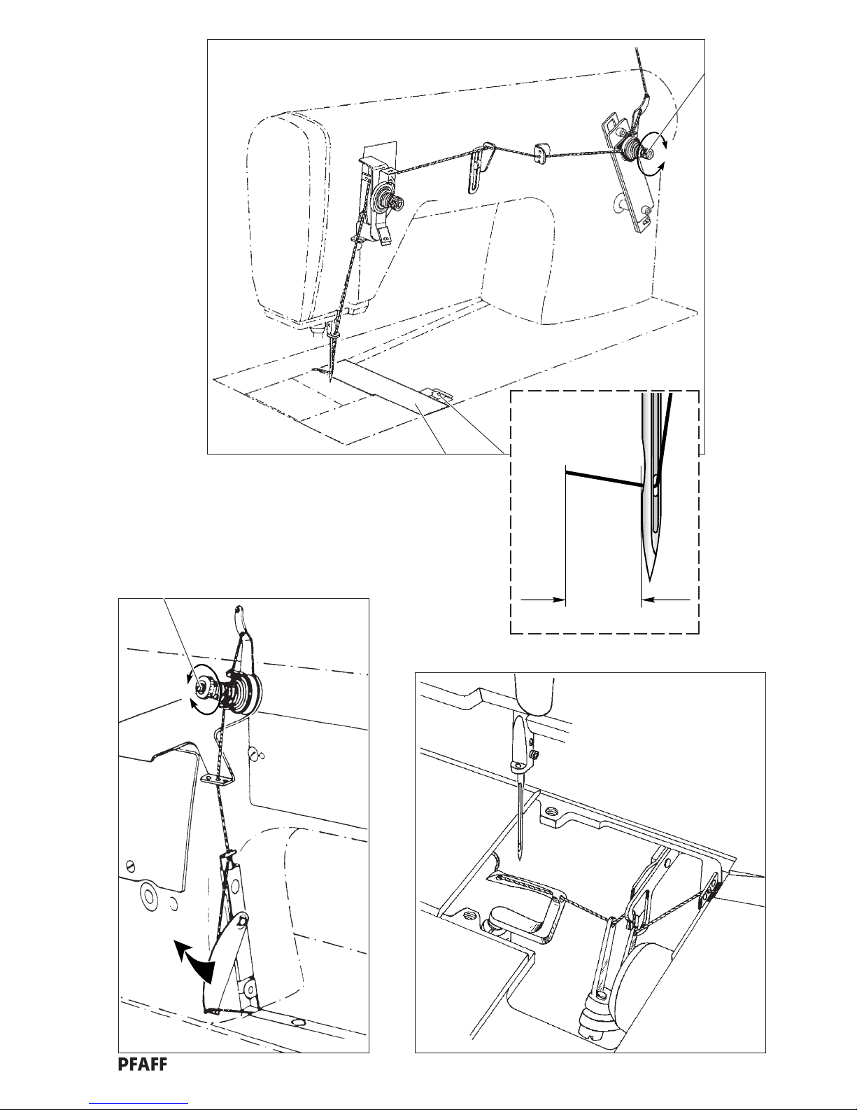
11 Needle thread and hook thread
11.1 Threading the needle thread
.1 Turn the machine off (mains switch).
.2 Thread the needle in accordance with fig. 1 (taking care to maintain the tension; Chapter 11.2)
.3 Pull the needle thread approx. 7 cm (2 3/4 inches).
11.2 Adjusting the needle thread tension
Milled nut 1 (fig. 1)
+ = more tension
- = less tension
11.3 Threading the hook thread
.1 Turn the machine off (mains switch).
.2 Remove cover 2 (fig. 1) (catch 3)
.3 Thread the hook thread in accordance with fig. 2 and 3.
11.4 Adjusting the hook thread tension
Milled nut 4 (fig. 2)
+ = more tension
- = less tension
Page 13
13
3
2
1
+
-
+
-
4
1
Bi11-01.CDR
2
3
Bi11-02
Bi11-04 Bi11-03
ca. 7cm
Page 14

14
12 Top feed pressure and presser foot presser
Requirement: The pressure from the top feed 1 (fig. 2) and that of the presser foot should
be adjusted so that the workpiece is fed perfectly at all sewing speeds.
12.1 Adjusting the top feed pressure
Screw 3 (fig. 1)
+ = more tension
- = less tension
12.2 Adjusting the presser foot pressure
Milled ring 4 (milled nut 5)
+ = more tension
- = less tension
13 Adjusting the stitch length
Adjusting lever 6 (fig. 3)
Page 15
15
2
Bi12-02.CDR
Bi12-03.CDR
3
6
1
2
45
1
3
+
-
+
-
Bi12-01.CDR
Page 16
16
14 Preparing for adjustments
Note: The bearing disc 1 (fig. 1) is provided with four holes so that the machine can be set at the
required needle bar position.
After positioning the needle bar (handwheel) insert the cylindrical pin 2 into the desired hole
so that it sticks securely in the recess behind the bearing disc, thus ensuring that the
selected setting is fixed.
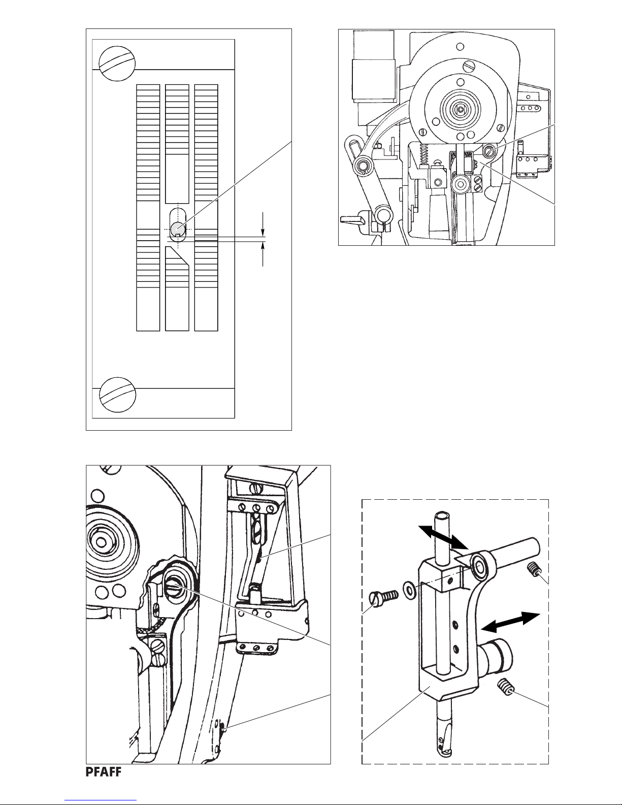
15 Needle position in the needle hole
Note: For the following adjustment it is recommended to:
- remove the presser foot
- insert a new needle.
15.1 Across the sewing direction
Requirement: The needle 3 (fig. 2) should enter the middle of the needle hole across the
sewing direction.
.1 Loosen screws 4 and 5 (fig. 4).
.2 Move the needle bar frame 6 (fig. 3) in accordance with the requirement.
.3 Tighten screws 4 and 5 (fig. 4).
15.2 With the sewing direction
Requirement: Clearance between the needle 3 (fig. 2) and the front edge of the needle hole
should be approx. 0.8 mm.
.1 Loosen screws 4 and 5 (fig. 4).
.2 Swivel the needle bar frame 6 (fig. 3) in accordance with the requirement.
.3 Tighten screws 5 and 7 (fig. 4).
ø5mm
21
Bi14-01
1
Page 17
17
4
Bi14-04
5
Bi14-05
Schematic diagram
7
6
Bi14-03
3
6
4
5
7
4
7
5
0,8mm
Bi14-02.CDR
2
3
Page 18

18
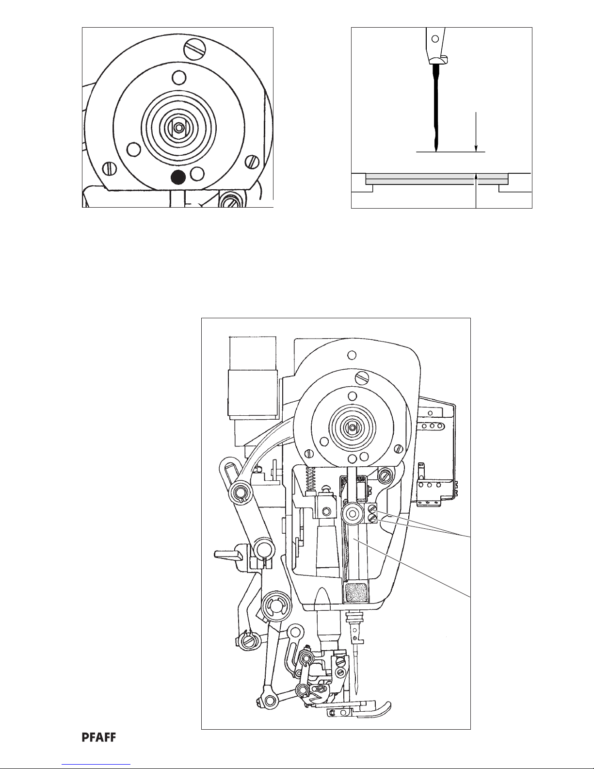
16 Preadjusting the needle height
Requirement: At the top dead centre of the needle bar (= adjustment hole “1”; fig.1), the
distance between the top edge of the needle plate and the point of the needle
must be 11 mm (approx. 1/2 inch) (fig. 2).
.1 Bring the needle bar 1 (fig. 3) to its top dead centre (handwheel).
.2 Insert the cylindrical pin (see chapter 14) in hole “1” (fig. 1) of the bearing disc
- the machine is blocked.
.3 Move the needle bar 1 (fig. 3) in accordance with the requirement (screws 2).
.4 Remove the cylindrical pin.
Page 19
19
Bi01-01
1
1
2
Bi16-02.CDR
11mm
Bi14.03
3
1
2
Page 20
20
2
1
Bi14-02H.CDR
Bi12-03.CDR
1
6
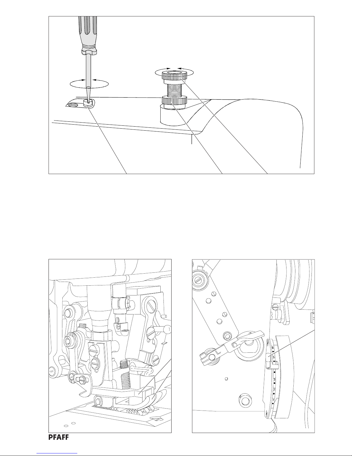
17 Bottom feed settings
17.1 Zeroing the main feed dog
Requirement: With the stitch length set at “0” (stitch length lever 1, fig. 1), the main feed
dog 6 (fig. 2) should not move laterally.
.1 Loosen limiting screw 2 (fig. 3) to such an extent as that the stitch length “0” can be set with the
stitch length adjustment lever 1 (fig. 1).
.2 Set the stitch length at “0”.
.3 Loosen the clamp screw 3 (fig. 4) just far enough so that the reversing crank can only be turned on its
shaft using a small amount of force.
.4 Note: In order to be able to see more effectively that the feed is at a standstill, insert a
screwdriver in the clamp slot of the feed crank 5 (fig. 5).
.5 While continually turning the handwheel, change the position of the reversing crank 4 (fig. 4) in such a
way that the main feed dog (fig. 2) does not move laterally i.e. the screwdriver in the clamp slot of the
feed crank 5 (fig. 5) does not move.
.6 Tighten the clamp screw 3 (fig. 4).
.7 Carry out a check (remove the screwdriver from the clamp slot).
.8 Carry out the adjustment in accordance with chapter 17.2.
17.2 Limiting the shortest stitch length to 3 mm
Tighten the limiting screw 2 (fig. 3) enough so that no stitch length shorter than 3 mm can be set with
the stitch length adjustment lever 1 (fig. 1).
Page 21
21
5
Bi17-03.CDR
3
4
Bi17-04.CDR
2
Bi17-03
34
4
Bi17-05x.CDR
5
Page 22

22
17.3 Main feed and differential feed synchronicity
Requirement: at:
- stitch length 4 mm
- cam setting “0”
both bottom feed dogs (main feed dog 6 and differential feed dog 7; fig. 6)
must make the same movement when the handwheel is turned.
.1 Set the stitch length at 4 mm (stitch length adjustment lever 1; fig. 7).
.2 Set the control cam 8 (fig. 8) at “0” (turn cam carrier 9 on the shaft).
Note: With the control cam set at “0”, the actuating lever 10 must have a little bit of play;
see arrow in fig. 8.
.3 Loosen clamp screw 11 (fig. 9) just enough so that the reversing crank 12 can only be turned on its
shaft using much force.
.4 While continuing to turn the handwheel, change the position of the reversing crank 12 (fig. 10)
so that the main feed dog 6 (fig. 6) and the differential feed dog 7 carry out the same motion.
.5 Tighten clamp screw 12 (fig. 10).
Page 23

23
Bi17-04.CDR
12
Bi17-03
9
11
12
7
Bi12-03.CDR
8
98
10
Bi17-16x.CDR
6
7
Bi14-02N.CDR
6
10
1
Page 24

24
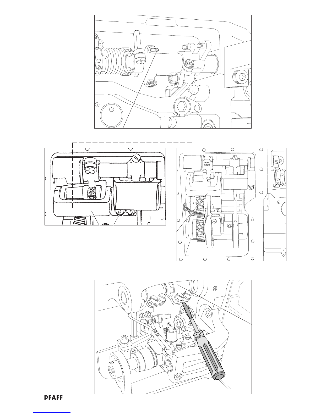
17.4 Lateral motion of main and differential feeds
Requirement: at:
- stitch length 4 mm
- cam setting “0”
- needle bar position 0.8 mm below its t.d.c. (top dead centre)
the main feed dog 6 (diag 12) and the differential feed dog 7 should not move
when the lever 13 (diag 11) is activated).
.1 Loosen the feeding motion eccentrics 14 (fig. 13) and 15 a little (4 screws).
.2 Using the handwheel, bring the needle bar into a position 0.8 mm below its t.d.c. (= hole “4”, fig. 14)
and lock it in this position with the cylindrical pin.
.3 Set the stitch length at 4 mm (stitch length adjustment lever 1, fig. 15).
.4 Set the control cam 8 (fig. 16) at "0" (turn cam carrier 9 on its shaft).
Note: In order to be able to see more effectively that the feed is at a standstill, insert screwdrivers
in the clamp slots of the feed cranks 5 and 16 (fig. 17).
.5 While continually moving the lever 13 (fig. 11) up and down, turn the feeding motion eccentrics 14
and 15 (diag 13) in such a way that the notch can be seen and the main feed dog 6 (fig. 12) and the
differential feed dog 7 (i.e. the screw-driver) do not move all.
.6 Screw the feeding motion eccentrics 14 and 15 tight in this setting.
.7 Remove the cylindrical pin.
6
7
11
12
Bi14-02N.CDR
Bi17-09.CDR
13
Page 25

25
15
16
89
14
Bi01-01
4
Bi17-16.CDR
17
Bi17-5xx.CDR
Bi12-03.CDR
13
Bi17-04.CDR
14(2x)
15(2x)
1
516
Page 26

26
17.5 Lifting motion of the main and differential feeds
Requirement: With the needle bar at its t.d.c. (= adjustment hole “1”) the notches in the feed
lifting eccentrics 17 and 18 (fig. 18 and 20) should point directly downwards.
.1 Loosen the 2 screws 19 and the two screws 20 (fig. 20).
.2 Using the handwheel, bring the needle bar to its t.d.c. (adjustment hole “1”, fig. 19) and lock it in this
position with the cylindrical pin.
.3 Adjust both feed lifting eccentrics 17 and 18 in accordance with the requirement.
.4 Tighten the two visible screws 19 and 20.
.5 Turn the handwheel until the other two screws 19 and 20 are visible. Tighten these screws also.
.6 Remove the cylindrical pin.
Page 27

27
18
Bi17-18.CDR
19(2x) 18
17
20(2x)
20
Bi17-20.CDR
17 19(2x) 18
20(2x)
19
Bi01-01
1
Page 28

28
17.6 Setting the feed dog
Requirement: at the maximum stitch length setting and with the needle bar at its t.d.c.
(= adjustment hole “1”; fig. 21):
- the main feed dog 6 (fig. 24) and the differential feed dog 7 should be in the
middle of the needle plate cutout;
- the main feed dog 6 and the differential feed dog 7 should be parallel to the
needle plate (fig. 23);
- the main feed dog should be 1.4 mm above the needle plate;
- the differential feed dog should be 1.9 mm above the needle plate;
- there should be a clearance of 4 mm between the main feed dog 6 and the
differential feed dog 7
Note: it is useful for the following adjustments to remove the presser foot.
.1 Set the longest stitch length (stitch length adjustment lever 1; fig. 22)
.2 Using the handwheel, bring the needle bar to its t.d.c. (= adjustment hole “1”, fig. 21) and lock it in
this position with the cylindrical pin.
.3 Loosen screws 21 (fig. 25) and 22 in the feed lifting cranks.
.4 Loosen screws 23 and 24 in the feeding motion cranks.
.5 Position the main feed dog 6 (fig. 24) and the differential feed dog 7 in the middle of the needle plate
cutout; set the clearance between the feed dogs at 4 mm.
.6 Set the height of the main feed dog at 1.4 mm (move main feed dog carrier 25 either up or
down).
.7 Set the height of the differential feed dog at 1.9 mm (move differential feed dog carrier 26 up or
down).
.8 Position the main feed dog parallel to the needle plate (turn eccentric split ring 27).
.9 Position the differential feed dog parallel to the needle plate (turn eccentric split ring 28).
.10 Taking care to maintain the settings, tighten screws 21; 22; 23; 24.
.11 Remove the cylindrical pin.
Page 29

29
Bi01-01
1
21
1.9mm
1.4mm
4mm
parallel to needle plate
Bi17-21.CDR
23
main feed dog 6
differential feed dog 7
Bi20-03.CDR
Bi12-03.CDR
22
24
21 22
Bi17-20.CDR
28
27
24
23
26
25
25
1
7
6
needle plate
Page 30

30
18 Top feed settings
18.1 Front connecting rod to the top feed drive
Requirement: With the needle bar 0.8 mm below its t.d.c. (= adjustment hole “4”) there
should be a clearance of approx. 16.5 mm (0.65 inches) between the eye of
the connecting rod 1 (fig. 2) and the machine housing 2.
.1 Bring the needle bar into a position 0.8 mm below its t.d.c. (handwheel) and lock it in this position
with the cylindrical pin.
.2 Loosen screw 3 (fig. 4).
.3 Change the size of the clearance in accordance with the requirement by pulling out or pushing back
the connection rod 1.
.4 Tighten screw 3.
.5 Carry out a check.
.6 Remove the cylindrical pin.
Page 31

31
Bi18-16
Bi18-05
4
1
4
Bi01-01
16.5mm
Bi18-17.CDR
3
2
2
1
3
1
2
Page 32

32
18.2 Synchronicity of top and bottom feeds
Requirement: with: - stitch length 4 mm
- cam setting “0”
- connecting rod 4 (fig. 5) attached
the top feed 5 (fig. 6) and the bottom feed dogs 6 (see chapter 17) must make
the same motion when the handwheel is turned.
.1 Set the stitch length at 4 mm.
.2 Attach connecting rod 4 (fig. 5).
.3 Set the control cam 8 (fig. 8) at position “0” (turn the cam carrier 6 on its shaft).
Note: The actuating lever 10 must have a little bit of play when the control cam is set at “0”;
(see arrow in fig. 8).
.4 Basic position of the top feed driving eccentric 11:
When the needle bar is 0.8 mm below the t.d.c. (adjustment hole “4”; fig. 9) the slot in the top feed
driving eccentric 8 (arrow in fig. 8) must point to the operator (screws 12).
.5 While continually turning the handwheel and observing the lateral movement of the top feed and the
bottom feed dog, adapt the lateral movement of the top feed to equal that of the bottom feed dogs by
turning the top feed driving eccentric 11 (screws 12).
Page 33

33
Bi01-01
4
7
9
Bi12-03.CDR
7
4
5
Bi17-03x.CDR
10
8
Bi17-16x.CDR
89
10
6
Bi18-04x.CDR
65
Bi18-05
11
12
Page 34

34
18.3 Top feed - lifting motion
Requirement: with:
- stitch length 4 mm
- cam setting “0”
- connecting rod 4 (fig. 11) attached
the top feed 5 (fig. 12) must touch the bottom feed dog when the bottom
feed dog reaches the top edge of the needle plate on its way up (fig. 13).
.1 Remove the face cover.
.2 Set the stitch length at 4 mm (stitch length adjustment lever 7; fig. 14).
.3 Attach connecting rod 4 (fig. 11).
.4 Set control cam 8 (fig. 16) at “0” (turn cam carrier 9 on its shaft).
Note: The actuating lever 10 must have a little bit of play when the control cam is set at “0”;
(see arrow in fig. 16).
.5 Adjust in accordance with the requirement: eccentric 13 (fig. 17; screws 14).
18.4 Top feed - stroke
Requirement: when the stitch length is set at 4 mm,
- the presser foot 15 (fig. 12) is touching the needle plate 16 and
- the top feed 5 is at its t.d.c.,
the distance between the top edge of the needle plate 16 and the bottom edge
of the top feed should be 3 mm.
.1 Set the stitch length at 4 mm (stitch length adjustment lever 7; fig. 14).
.2 Bring the top feed 5 (fig. 12) to its t.d.c. (handwheel)
.3 Position the top feed parallel to the needle plate (pin 17, screw 18). Basic position of the pin 17
(fig. 12): with the eccentricity away from the machine.
.4 Position pin 19 (fig. 15) at the bottom of the elongated hole (nut) in the connecting lever 20.
.5 Set the clearance at 3 mm.
.5.1 Basic position of the eccentric pin 21 (fig. 15): eccentricity facing downwards (screw 22).
.5.2 Rough adjustment: loosen screw 23 and move actuating lever 24 (arrow in fig. 15) so that a distance
of 3 mm exists between the top feed 5 (diag 12) and the needle plate 16.
.5.3 Fine adjustment: eccentric pin 21 (screw 22).
.6 Tighten all the screws.
Page 35

35
Bi14-03A
3mm
Bi14.03
Bi18-10.CDR
14
10
21
22
24
19
20
17
16
15
16
Bi17-16x.CDR
10
8
9
16
5
15
15
5
18
Bi12-03.CDR
Bi17-03x.CDR
4
23
7
17
14
13
Bi18-12
11
12
Page 36

36
19 Basic stitch length (Adjustment not required for -2/45 since it is adjusted to 2.2 mm ex works)
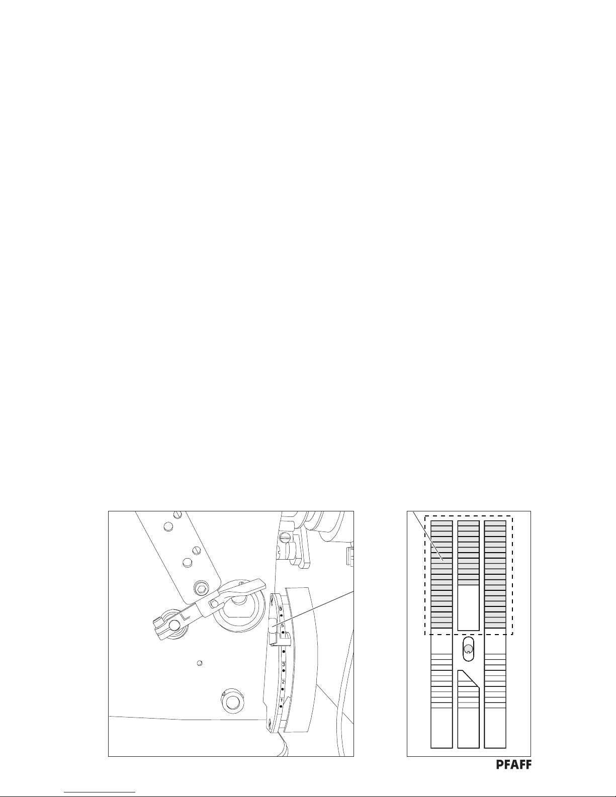
19.1 Adjust basic stitch length to 3 mm
Note: In order to adjust the basic stitch length, the feed settings must be correct, as laid out
in chapters 17 and 18.
Requirement: When:
- the stitch length is set at 3 mm;
- the key (fig. 1) is pressed;
- the cylinder 1 (fig. 4) is as far out as possible;
- the adjustment connecting rod 2 (fig. 5) is attached;
the stitch length should be 2 mm.
.1 Attach adjustment connecting rod 2 (fig. 5).
.2 Remove the top feed 3 (fig. 2) and the differential feed dog 4.
.3 Set the stitch length at 2 mm (adjustment lever 5; fig. 3).
.4 Switch the machine on (mains switch).
.5 Press key (fig. 1)
- cam 6 (fig. 6) runs at 10.5 on the scale.
.6 Turn off the machine! (mains switch)
.7 Pull the cylinder 1 (fig. 4) as far out as possible by hand.
.8 Place a piece of thin cardboard underneath the presser foot.
.9 Turn the handwheel slowly until 11 holes have been made in the card by the needle (diag 7).
.10 Measure the entire distance from the first hole to the last. (this distance should be 30 mm =
stitch length of 3 mm.)
.11 Correction:
Lever 7, screw 8 (fig. 4).
.12 Screw the top feed 3 (diag 2) and the differential feed dog 4 back on.
Tastenfeld von -11/43, -11/45, -13/45
1
Page 37

37
5
Bi17-03x.CDR
2
4
3
Bi12-03.CDR
5
2
Bi18-04x.CDR
43
Bi12-08
7
1
8
Bi19-05.CDR
7
Bi19-09.CDR
6
6
11 perforations
= 10 stitches
= 30 mm
Page 38

38
20 Presser foot settings
20.1 Clearance between presser foot and needle plate
Requirement: With the hand lever 1 (fig. 1) raised the clearance between the presser foot 2
and the needle plate 3 (fig. 3) should be 5 mm.
.1 Bring the top feed 4 (fig. 3) to its highest position (handwheel).
.2 Lift the presser shaft 5 and slide the 5 mm thick adjustment gauge 6 (fig. 3) from the back,
under the presser foot joint.
.3 Loosen screw 7 and bring the presser shaft lifter 8 to its bottom resting position.
Note: Take care that the hand lever 1 is still in its upwards position!
.4 Tighten screw 4.
.5 Check that:
- the edge of the presser foot is parallel to the needle plate cutout
- the needle enters the presser foot needle hole exactly in the middle.
If necessary, align the presser foot as described in chapter 20.3.
20.2 Presser foot stroke with the automatic presser foot lifter
Requirement: With the plunger 9 (fig. 1) retracted, the clearance between the presser foot 2
and the needle plate should be 7 mm (fig. 3)
.1 Loosen nut 10.
.2 Twist the plunger 9 into or out of the presser shaft lifter 11 (fig. 1) until the presser foot 2 is
approx. 7 mm above the needle plate 3 when the plunger 9 is retracted.
.3 Tighten nut 10.
Bi21-01
Page 39

39
Bi14-03
1
Bi14-03B
7mm
2
3
4
2
3
1
9
8
7
11
5
Bi20-03.CDR
10
105
1
6
Page 40

40
20.3 Aligning the presser foot
Requirement: The presser foot 2 (fig. 4) should be positioned in such a way that:
- the needle enters the middle of the needle hole in the presser foot
- the edge of the presser foot is parallel to the needle plate cutout of the
bottom feed dog.
Note: All of the moving parts of the top feed drive must function easily and without play
(oil regularly!).
.1 Bring the top feed 4 (fig. 4) into its highest position (handwheel).
.2 Lift the presser foot 2 (hand lever 1; fig. 8).
.3 Slide the 5 mm thick adjustment gauge 11 (fig. 6) under the presser foot from the back.
.4 Remove the bearing pin 12 (fig. 7 and 9) (screw 13; fig. 9).
.5 Pivot the connecting joint 14 out of the bracket of the feed driving lever 15.
.6 Push out the eccentric pin 16 (fig. 7) (screw 17).
.7 Loosen screw 7 (fig. 4).
.8 Align the presser foot 2 in accordance with the requirement.
.9 Bring the presser shaft lifter 8 to its bottom resting position.
Note: Take care that the hand lever 1 (fig. 4) is still in its upwards position!
.10 Let the presser foot 2 come to rest on the needle plate 3 (hand lever 1) (fig. 4) and loosen
screw 18 (fig. 8).
.11 Pivot the connecting joint 14 (fig. 8) into the bracket of the feed driving lever 15.
.12 Mount the bearing pin 12 (fig. 9) (screw 13).
Note: Pay attention to the ease of movement. If necessary, align the feed driving
lever 15 (fig. 7).
.13 13 Using the handwheel, bring the needle bar to a position 0.8 mm below its t.d.c.
(= adjustment hole “4”; fig. 5) and lock it into this position with the cylindrical pin.
.14 Position the top feed foot 4 (fig. 4) in the middle of the presser foot cutout in the sewing direction and
tighten screw 18.
.15 Remove the cylindrical pin from the bearing disc.
.16 Loosen screw 19 (fig. 8).
.17 Connect the connection lever 20 and the connecting rod 21 (eccentric pin 16).
.18 Set the eccentric pin 16 in such a way that the largest eccentricity is pointing downwards;
tighten screw 19.
.19 Press the connection lever 20 in the feed direction until it touches the eccentric pin 16.
Tighten screw 19.
.20 Laterally align the top feed foot 4 in such a way that it does not touch the presser foot 2
(srew 21; fig. 9).
Bi21-01
Page 41

41
5mm
Bi14-03B
6
Bi19-07
7
15
Bi01-01
7
4
2
Bi14-03
4
4
5
21
6
16
12
16
8
3
Bi19-08
8
19
21
3
2
Bi20-03.CDR
1
14
15
17
16
20
18
15
13
12
21
9
1
Page 42

42
21 Hook settings
21.1 Hook avoiding motion
Requirement: With the needle bar at its t.d.c. (t.d.c. = adjustment hole “1”) the notch in the
avoiding eccentric 1 should be directly under the axle centre
(see arrow in fig. 2).
.1 Loosen both screws 2 (fig. 3).
.2 Using the handwheel, position the needle bar at its t.d.c. (= adjustment hole “1”, fig. 1) and lock it in
this position with the cylindrical pin.
.3 Turn the lateral eccentric 1 (fig. 3) in such a way that the notch (arrow in fig. 2) points directly
downwards.
.4 Tighten the visible screw.
.5 Remove the cylindrical pin from the bearing disc.
.6 Tighten the second screw 2.
.7 Carry out a control.
Page 43

43
1
Bi01-01
1
3
Bi17-20.CDR
Bi20-02.CDR
1
2
12(2x)
Page 44

44
21.2 Carry out a control.
21.2.1 Machines without the thread trimmer -900/..
Requirement: When the hook carrier 3 (fig. 4) is standing vertical, the clearance between the
highest point of the back of the hook and the needle plate support surface
should be 0.7 mm (fig. 5).
.1 Remove the cover plate 4 (fig. 6). Remove the needle plate 5 and the feed dog 6.
.2 Lay the adjustment gauge (No. 61-111 642-19) onto the needle plate support surface (fig. 5).
.3 Position the hook carrier 3 vertically (handwheel).
.4 Loosen the screws 7 (fig. 4) and 8 for the eccentric bearing pin 9.
.5 Carry out the adjustment in accordance with the requirement (eccentric bearing pin 9).
.6 Tighten screws 7 and 8.
.7 Carry out a control.
If the required clearance of 0.7 mm is not reached, continue with points .8 and .9.
.8 Replace the spacer 10 (fig. 8) (screw 11).
.9 Position the hook blade parallel to the side edge of the needle plate cutout (fig. 7) (screw 11).
21.2.2 Machines with the thread trimmer -900/..
Requirement: When the hook carrier 3 (fig. 4) is standing vertical, the clearance between the
highest point on the back of the hook and the bottom of the thread trapper 12
should be 0.3 mm (fig. 8).
.1 Remove the cover plate 4 (fig. 6). Remove the needle plate 5 and the feed dog 6.
.2 Position the hook carrier 3 vertically (handwheel).
.3 Loosen screw 7 (fig. 4) and 8 for the eccentric bearing pin 9.
.4 Carry out the adjustment in accordance with the requirement (eccentric bearing pin 9).
.5 Tighten screws 7 and 8.
.6 Carry out a check.
If the required clearance of 0.3 mm is not reached, continue with points .7 and .8.
.7 Replace the spacer 10 (fig. 8) (screw 11).
.8 Position the hook blade parallel to the side edge of the needle plate cutout (fig. 7) (screw 11).
Bi21-01
Page 45

45
7
parallel
Bi20-06.CDR
Stitch plate support surface
5
Bi20-04.CDR
Gauge
Hook
0,7mm
0,7mm
Stitch plate
support surface
Gauge
8
0.3mm
12
Bi20-09.CDR
10
4
Bi17-05.CDR
9
7
8
3
11
564
6
Bi18-04x.CDR
11
Page 46

46
21.3 Adjusting the hook angle
.1 Raise the presser foot (hand lever).
.2 Remove the cover plate 4 (fig. 6). Remove the needle plate 5 and the feed dog 6.
.3 Loosen the screw 13 (fig. 10) in the hook carrier 3.
.4 Position the hook carrier 3 vertically (handwheel).
.5 Lay the hook adjustment gauge 14 (Part No. 61-111 643-06) against the left edge of the cover plate
guide (arrows in fig. 9) and slide it against the hook. Bring the Hook to rest against the gauge.
.6 Tighten the screw 13 in the hook carrier 3.
21.4 Hook-to-needle clearance in sewing direction (preadjustment)
Requirement: Viewed in the direction of sewing, the clearance between the hook point and
the needle should be approx. 0.1 mm (fig. 10)
.1 Turn the handwheel until the hook point, coming from the right hand side, reaches the left side of the
needle.
.2 Loosen the hook unit 15 (fig. 11) (screws 16).
.3 Align the hook unit 15 in accordance with the requirement.
.4 Tighten screws 16.
21.5 Hook-to-needle clearance in hook direction (across the sewing direction)
Requirement: At the right turning point of the hook, the hook point should be 3.6 mm from
the needle (fig. 12).
.1 Bring the hook to its right turning point (handwheel).
.2 Loosen screw 17 (fig. 13) in the hook carrier.
.3 Lay the 3.6 mm feeler gauge (fig. 12; adjustment gauge 61-111 643-06) against the needle with its
notch facing in the direction of feed.
.4 Taking care that the drive connecting rod 18 is standing vertically, turn the eccentricc ball pin 19 until
the hook point touches the right hand edge of the feeler gauge (6 mm open ended wrench).
.5 Tighten screw 17 in the hook carrier.
Bi21-15
Page 47

47
Bi21-10.CDR
13
3
14
Bi21-11
10
13
3
0:1mm
9
Bi17-05.CDR
15
Bi21-12
16
Bi21-13
12
Bi21-13.CDR
Needle
Hook
3,63,6
3,63,6
3,6
3:6mm
Gauge
13
11
19
17
18
2°
Page 48

48
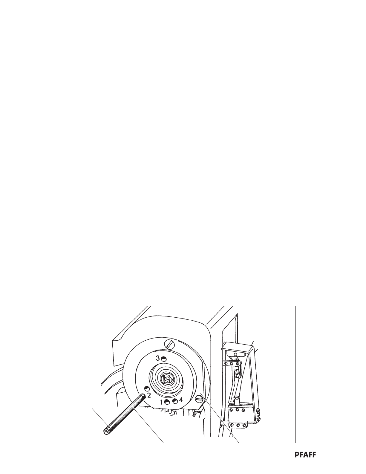
21.6 Hook motion (timing)
Requirement: If, when turning the handwheel
- the point of the hook, coming from the right hand side, is just to the righthand side
of an 80 Nm needle (fig. 14)
and
- any further upwards movement of the needle bar is blocked by the screw
clamp (fig. 16) in this position, the point of the hook should
- be just on the right hand side of the needle (fig. 15) when turning the
handwheel in the opposite direction until the clamp screw touches the needle
bar frame.
.1 Insert a new 80 Nm needle.
.2 Turn the handwheel until the point of the hook, coming from the right hand side, is just on the left
hand side of the needle (fig. 14).
.3 In this position, fasten the clamp screw (fig. 16) onto the needle bar so that the clamp screw touches
the needle bar frame (upwards movement of the needle bar is blocked).
.4 Turn the handwheel in the opposite direction until the screw clamp comes to rest again on the
needle bar frame.
In this position, the hook point should be just to the right of the needle (fig. 15).
.5 Alteration if necessary:
- Remove the screw clamp
- Turn the cog 20 (fig. 17) accordingly (screws 21).
Page 49

49
Bi21-15.CDR
14 15
Bi21-16.CDR
16
Part No. 08-880 137-00
Bi21-17
17
Bi17-04.CDR
2021(2x)
Page 50

50
21.7 Needle height and hook-to-needle clearance (final adjustment)
Requirement: When the hook point reaches the left side of the needle, coming from the
right hand side, the top edge of the eye of the needle should be 1.0-1.2 mm
underneath the bottom edge of the hook (fig. 18).
Additionally, in this position, there should be a clearance of 0.1 mm between
the hook and the needle.
.1 Turn the handwheel until the point of the hook reaches the left hand side of the needle, coming from
the right hand side.
.2 Loosen the screws 22 (fig. 20).
Note: Do not turn the needle bar 23 when carrying out the following adjustment!
.3 Raise or lower the needle bar 23 so that there is a clearance of 1.0-1.2 mm between the top edge of
the needle eye and the bottom edge of the hook.
.4 Tighten screws 22.
.5 Check the adjustment.
.6 Check that the clearance between the hook and the needle (fig. 19) is 0.1 mm.
Alteration: see chapter 21.4.
Page 51

51
Bi21-18.CDR
18
1.0 - 1.2mm
Bi14-03
22
23
20
19
Bi21-19.CDR
0,1mm
Hook
Page 52

52
22 Rear needle guard
22.1 Adjusting the height of the rear needle guard
Requirement: With the needle bar at its t.d.c. (= adjustment hole “3”, fig. 3) the upper edge
of the vertical surface of the rear needle guard 1 (fig. 2) should be at the same
height as the upper edge of the eye of the needle (arrow in fig. 1).
.1 Bring the needle bar to its bottom dead centre (b.d.c.) (handwheel).
.2 Lock the needle bar in this position by inserting the cylindrical pin in hole “3” (fig. 3).
.3 Align the rear needle guard 1 (fig. 2) (screw 2)in such a way that the upper edge of the needle eye is
at the same height as the top end of the vertical surface of the needle guard (arrow in fig. 1).
.4 Remove the cylindrical pin.
.5 Carry out a check.
22.2 Clearance between the rear needle guard and the needle
Requirement: When the point of the hook, coming from the right hand side, has reached the
right hand side of the needle, the needle should still be touching the rear
needle guard 1 (arrow in fig. 4).
.1 Turn the handwheel until the point of the hook, coming from the right hand side, has reached the right
hand side of the needle.
.2 Move the carrier 3 (fig. 5) (screw 4) in such a way that the needle guard 1 just touches the needle
without pressing against it.
23 The hook-avoiding eccentric guard
Requirement: The hook-avoiding eccentric 5 (fig. 5) should at no stage of its motion touch
the guard 6.
Align the guard 5 in accordance with the requirement (screws 7; can be reached through the
mounting aperture).
Page 53

53
Bi22-21.CDR
Bi21-11
2
1
2
1
1
Bi01-01
3
3
Bi22-04.CDR
4
Bi22-05
5
6
Bi22-06
34
6
7
5
Page 54

54
24 Front needle guard
24.1 Adjusting the height
Requirement: The top edge of the front needle guard finger 1 (fig. 1) should be at the same
height as the bottom edge of the hook point when the point of the hook 2,
coming from the right hand side, has reached the middle of the needle.
The front needle guard finger 1 must be parallel to the hook blade.
.1 Turn the handwheel until the point of the hook 2, coming from the right hand side, has reached the
middle of the needle (arrow in fig. 3).
.2 Loosen the needle guard carrier 3 (fig. 2) (screws 4).
.3 Align the height of the needle guard finger 1 so that its top edge is flush with the bottom edge of the
hook point (fig. 1).
.4 Position the needle guard finger 1 parallel to the hook blade and tighten the screws 4.
24.2 Lateral adjustment
Requirement: When the hook point is exactly behind the middle of the needle, there should be a
clearance of 0.3 mm - 0.5 mm between the front needle guard finger 1 and the
needle (fig. 4)
.1 Bring the hook to its left turning point (handwheel).
.2 Move the needle guard carrier 3 (fig. 2) on its axle in such a way that at the left turning point of the
hook, the needle guard finger 1 does not come into contact with the hook (screw 5).
.3 Bring the hook point to a position behind the middle of the needle; fig. 3 (handwheel).
.4 Turn the needle guard carrier 3 (screw 5) in such a way that there is a clearance of 0.3 - 0.5 mm
between the needle and the needle guard finger (fig. 4).
Page 55

55
Bi24-01.CDR
1
2
Bi22-06
2
1
1
4
3
5
2
Bi24-04.CDR
0.3 - 0.5mm
3
4
1
Page 56

56
25 Needle thread puller
Requirement: The needle thread puller 1 (fig. 1) should be attached to the needle bar in such
a way that:
- it moves freely in the middle of the face slot
- it does not come into contact with anything at its top and bottom turning
points.
With the needle bar at its b.d.c., there should be a clearance of approx. 0.3 mm
between the bottom edge of the needle thread puller and the top edge of the
needle bar frame.
.1 Turn the handwheel until the screw 2 in the needle thread puller 1 (fig. 1) can be reached.
.2 Loosen the screw 2 slightly.
.3 Bring the needle bar to its b.d.c. (handwheel).
.4 Set the clearance at 0.3 mm in accordance with the requirement (metal ruler = 0.3 mm thick).
.5 Taking care that the needle thread puller 1 is in the middle of the face slot, tighten screw 2.
26 Needle thread regulator (basic setting)
Requirement: With the needle bar at its bottom turning point, the eyelet of the needle thread
regulator 3 should be at the same height as the hole in the needle thread
puller 1 (arrow in fig. 3).
Note: Depending on the workpiece and the type of thread, a small change in this basic setting
may be necessary.
.1 Bring the needle bar to its b.d.c. (handwheel).
.2 Loosen the retaining screw of the needle thread regulator (arrow in fig. 2).
.3 Move the needle thread regulator 3 in such a way that its eyelet is at the same height as the hole in
the needle thread puller 1 (arrow in fig. 3).
.4 Tighten the retaining screw of the needle thread regulator 3 (arrow in fig. 2).
27 Adjustable thread guide (basic setting)
Requirement: The thread guide (fig. 4) should:
- be fastened in the middle of the elongated hole
- be vertical.
Note: Depending on the type of thread and the stitch length, it may prove necessary to
make a small deviation from this basic setting.
.1 Adjust the thread guide 4 in accordance with the requirement (screw 5).
Page 57

57
0.3mm
Bi25-01
1
1
2
Bi26-01 Bi26-02
23
3
1
3
4
Bi27-01
4
5
Page 58

58
28 Hook thread regulator
Requirement: The distance between the front edge of the thread regulator 1 (fig. 1) and the
rear needle plate edge-guide should be 29 mm.
.1 Loosen the thread regulator 1 (fig. 1) (screws 2).
.2 Move the thread regulator 1 in accordance with the requirement.
.3 Taking care that the thread regulator 1 is laterally in the middle of the thread puller bracket 3,
tighten both screws 2.
.4 Carry out a check.
29 Hook thread controller
Requirement: The front edge of the thread controller 4 (fig. 3) should be approx. 8 mm
behind the front edge of the thread regulator 1.
.1 Move the thread regulator 4 (fig. 1) in accordance with the requirement (screw 5).
.2 Carry out a control.
30 Hook thread puller
Requirement: With the needle bar at its t.d.c. (=adjustment hole “1”, fig. 3), both eyelets of
the hook thread puller 3 should be just in front of the front edge of the thread
regulator 4 (fig. 5).
.1 Loosen screw 6 (fig. 1) a little until the hook thread puller 3 can be moved by hand on its stud.
.2 Bring the needle bar to its t.d.c. (handwheel).
.3 Insert the cylindrical pin into hole “1” in the bearing disc (fig. 2) (lock the position).
.4 Adjust the hook thread puller 3 in accordance with the requirement.
.5 Taking care that the bracket of the hook thread puller 3 has the same clearance laterally from the
thread controller 1, tighten screw 6.
.6 Remove the cylindrical pin.
Page 59

59
Bi29-04.CDR
5
4
1
3
4
Bi29-03.CDR
8mm
3
Bi28-01
1
1
2
5
4
3
6
Bi01-01
1
2
29mm
Page 60

60
31 Quick adjustment of the differential for altering the gathering
intensity
31.1 Zeroing the differential quick adjustment
31.1.1 Rough adjustment at the angle encoder 1 (fig. 2)
Requirement: After pressing the key:
- the actuating lever 2 should be at “0” on the control cam scale, and
- the sewing machine should sew smoothly (without fullness).
.1 Switch off the machine (mains switch).
.2 Remove the protective cover 1 from the angle encoder.
.3 Loosen the retaining screw of the angle encoder a little.
.4 Turn the machine on (mains switch): the key is activated automatically (LED on).
On the -2/45 the key must be activated manually.
.5 Set the stitch length at 4 mm.
.6 Attach the connecting rod 4 (fig. 3).
.7 Loosen screw 3 (fig. 2).
.8 Turn the angle encoder 1 (fig. 2) until the roller on the actuating lever 2 is at the “0” on the scale.
.9 In this position, tighten the retaining nut on the angle encoder.
.10 Place the roller of the actuating lever 2 against the control cam and tighten the screw 3 (fig. 3).
.11 Remove the connecting rod 4.
.12 - Carry out a control (see requirement)
- Screw the protective cover back on the angle encoder
- Mount the cover plate.
31.1.2 Fine adjustment at the Poti 0 (fig.4)
Requirement: When the key is activated (LED on), the machine should sew smoothly
(without fullness).
.1 Test seam
.2 If necessary, adjustment at the Poti “0”.
.3 To carry out the fine adjustment the connecting rod 4 must be attached again.
Note: The default setting of the Poti “0” (fig. 4) is the position “0” and as a rule it should not be
altered or altered very little (for altering the rough adjustment)!
Nevertheless, if the Poti “0” should be altered strongly, a rough adjustment of the
basic setting (“0” position of the Poti) can be made as follows:
- Turn Poti “0” 20 rotations to the left (direction -).
Page 61

61
1
2
123
4
3
4
Poti "0"
Bi17-16.CDR
Bi31-02.CDRBi1703x.CDR
Tastenfeld von -11/43, -11/45, -13/45
Page 62

62
31.2 Key allocation for positioning the cam against the actuating lever
Note: The operator can allocate any gathering intensity to any key desired.
31.2.1 Setting the gathering level of key
Press the key
Turn the Poti 1 until the desired cam position is reached; test seam.
31.2.2 Setting the gathering levels
Example:
Material: ..................................... home furnishing fabric
Band tension: ............................. none
Sewing thread: ........................... thickness 50
Machine rpm:............................. 3200 min
1
Length of the test sample: ......... 100 cm (26 inches)
Key Stitch length Gathered Cam
in mm length in cm position
4 100 0
495 6
489 8
484 9
480 10
476 11
470 12
465 13
461 14
458 15
3 54 10,5
3 52 11,5
3 48 12,5
3 44 13,5
3 42 14,5
339 15
Page 63

63
7
6
5
Tastenfeld von -11/43, -11/45, -13/45
Bi31-02.CDR
Bi19-04.CDR
Page 64

64
5
1
Bi32-01
32 Edge trimmer
32.1 Trimming motion
Requirement: The needle bar t.d.c. (adjustment hole “5”; fig. 1) = top turning point of the
knife.
.1 Switch on the edge trimmer (key , LED on; fig. 2).
.2 Bring the needle bar to its highest position (handwheel).
.3 Adjustment: Turn eccentric 1 until the upper knife is at its top turning point; screws 2 (fig. 3).
32.2 Zero point (no trimming motion)
Requirement: When turning the handwheel and with the edge trimmer switched off, the
upper knife should not move up or down.
.1 Switch off the edge trimmer (key , LED off; fig. 2).
.2 Turn the eccentric pin 3 (fig. 3) in such a way that the eyes of the levers 4 and 5 are at the same
level (screw 6).
.3 Turn lever 7 until the upper knife remains motionless when the handwheel is turned (screw 8).
32.3 Knife height
Requirement: With the upper knife at its lowest point, the front edge of the blade should be
approx. 0.5 mm underneath the top edge of the needle plate (fig. 4).
.1 Remove the presser foot.
.2 Switch on the edge trimmer (key , LED on; fig. 2).
.3 Bring the upper knife to its lowest position (handwheel).
.4 Move the upper knife 9 (fig. 5) in the knife holder in accordance with the requirement
(screws 10).
Page 65

65
3
9
10
0.5mm
1
2
3457 86
4
Bi32-05
5
Bi32-05
Bi3203
2
Tastenfeld von -11/43, -11/45, -13/45
Page 66

66
32.4 Aligning the upper knife in sewing direction
Requirement: There should be approx. 1 mm between the left edge of the upper knife and
the left edge of the needle plate insert (fig. 6).
Move the knife carrier 11 (fig. 7) in accordance with the requirement (screw 12).
32.5 Aligning the upper knife across the sewing direction
Requirement: The upper knife 9 should touch the stationary knife with a small amount of
pressure (The knife skid must not hit the stationary knife!)
.1 Switch on the edge trimmer (key , LED on, fig. 2).
.2 Bring the upper knife to its lowest position.
.3 Lay the upper knife onto the stationary knife with a small amount of pressure (screw 13; fig. 7).
Requirement: The upper knife 9 (fig. 8) should be slightly out of alignment with the
stationary knife (scissor effect).
.4 Position the knife carrier 11 (fig. 7) a little out of alignment with the stationary knife (screw 15).
32.6 Aligning the stop eccentric
Requirement: When the stopper 16 (fig. 9) is touching the eccentric 17, there should be a
clearance of approx. 5 mm between the front edge of the housing and the
lever 19 (fig. 10).
.1 Remove the air supply.
.2 Pull the stroke bar 20 downwards as far as it will go.
.3 Taking care that the stopper 16 is touching the eccentric 17, adjust eccentric 17 in accordance with
the requirement (screw 21).
.4 Replace the air supply.
Page 67

67
9
6
8
12 15
11
13
17
16
21
22
14
9
5mm
10
19
18
Bi32-09
Bi32-10
Bi32-08
7
Bi32-05Bi32-04.CDR
ca. 1mm
Page 68

68
33 Tape brake
33.1 Switching on
Switching on: Press the key (fig. 2) (LED on)
- Tape brake 1 (fig. 1) will now switch on automatically when a gathering level is
selected (keys to ).
When the key is pressed (sewing without fullness), the tape brake does not
function. Only the pre-tension 2 functions.
33.2 Switching off
Switching off: Press the key (LED off).
- The tape brake is off regardless of what key is pressed.
33.3 Adjusting the brake intensity
Knurled ring 3 (fig. 1)
+ = More braking effect
- =less braking effect
33.4 Pre-tension
Knurled nut 4 (fig. 1)
+ = More braking effect
- =less braking effect
Page 69

69
1
Bi33-01.CDR
3
1
+
-
+
-
2
4
Tastenfeld -11/43 -11/45 -13/45
2
Bi02-03.CDR
Page 70

70
34 Care and maintenance
34.1 Sewing machine
.1 Oiling the sewing machine
see chapter 8.1.
.2 Cleaning the sewing machine
.1 The required cleaning cycle of the sewing machine is dependent on the following factors:
- Single or multiple shift operation
- Workpiece dependent dust accumulation
- Top speed
- Continuous or changing operation
Therefore it is only possible to give optimum cleaning instructions for every individual case alone.
This can only be done in cooperation between the company maintenance-personel, and the authorized
service personel, taking into account the above mentioned factors and the applicable instruction
booklet.
.2 To avoid operational disturbances, we recommend the following cleaning measures for one
shift operation:
- Entire unit 1 x weekly
- Hook area at least 1 x daily
34.2 Air filter/lubricator
.1 Water trap
Max. water level = see arrow in fig. 1
.1 Empty the container once a day (screw 2).
.2 Air filter
Note: Clean the filter when the working pressure of 6 bar is no longer attained.
.1 Switch off the compressed air.
.2 Remove the container 1.
.3 Remove the disc 3.
.4 Remove the filter 4.
.5 Clean the filter and the container with petrol.
.6 Blow compressed air through the filter from the inside outwards.
.7 Do not forget the seal ring when reassembling.
.8 Open the compressed air.
Page 71

71
3
1
2
1
4
Bi34-01.CDR
34.3 Lubrication recommendation
Only use oil with an average viscosity of 10.0 mm2/s at 40°C and a density of 0.847 g/cm3 at 15°C.
We recommend Pfaff sewing machine oil: part No. 280-1-120 105.
The oils used must not - or only to a negligible extent - effect swelling or shrinkage of the sealing
substances under any operating conditions.
Page 72

G.M. PFAFF
Aktiengesellschaft
Postfach 3020
D-67653 Kaiserslautern
Königstr. 154
D-67655 Kaiserslautern
Telefon: (0631) 200-0
Telefax: (0631) 172 02
Telex: 45753 PFAFF D
Gedruckt in der BRD
Printed in Germany
Imprimé en R.F.A.
Impreso en la R.F.A.
Stampato in R.F.G.
ïôÐe aôaÇï ÖÑÃ
 Loading...