

Page 1

296-12-18 591/002
Instruction Manual engl. 07.17
This instruction manual applies to machines
from the serial number2 792 321 and
software version 0352/013 onwards.
INSTRUCTION MANUAL
3811
-3/55; -15/65; -16/65
Page 2

Reprinting, reproduction and/or translation of PFAFF instruction manuals
(including parts thereof) is only permitted with our prior agreement and
citation of the source.
PFAFF Industriesysteme
und Maschinen GmbH
Hans-Geiger-Str. 12 - IG Nord
D-67661 Kaiserslautern
This instruction manual applies to all models and subclasses listed in
Chapter 3 Technical Data.
Page 3

Table of Contents
Contents ..................................................................................Page
1 Safety .................................................................................................................................... 7
1.01 Directives ............................................................................................................................... 7
1.02 General safety instructions .................................................................................................... 7
1.03 Safety symbols ...................................................................................................................... 8
1.04 Special points of attention for the owner-operator ................................................................ 8
1.05 Operating personnel and technical staff ................................................................................ 9
1.05.01 Operating personnel .............................................................................................................. 9
1.05.02 Technical staff ........................................................................................................................ 9
1.06 Danger warnings ..................................................................................................................10
2 Proper Use ..........................................................................................................................11
Proper Use 11
3 Technical Data
.............................................................................................................................................................................................. 12
3.01 PFAFF 3811 ......................................................................................................................... 12
4 Disposal of the Machine .................................................................................................... 13
5 Transportation, Packaging and Storage .......................................................................... 14
5.01 Transport to the customer's premises ................................................................................ 14
5.02 Transportation within the customer's premises .................................................................. 14
5.03 Disposal of the packaging materials ....................................................................................14
5.04 Storage ................................................................................................................................ 14
6 Work Symbols ....................................................................................................................15
7 Operating Controls ............................................................................................................16
7.01 Main switch ......................................................................................................................... 16
7.02 Pedal .................................................................................................................................... 16
7.03 Hand lever to raise the presser foot .................................................................................... 17
7.04 Knee switch ......................................................................................................................... 17
7.05 Edge guide (only with PFAFF 3811-3/55 and PFAFF 3811-15/65) ....................................... 18
7.06 Lever for releasing thread tension ....................................................................................... 18
7.07 Keypad ................................................................................................................................. 19
1 19
1 19
7.08 Control panel ........................................................................................................................20
8 Set-up and Initial Start-up ............................................................................................. 21
8.01 Set-up .................................................................................................................................. 21
8.01.01 Setting the table height ....................................................................................................... 21
8.01.07 Assembling the reel stand ................................................................................................... 25
8.01.08 Mounting the control panel on the table top ....................................................................... 25
8.02 Initial commissioning ........................................................................................................... 26
8.03 Switching the machine on/off .............................................................................................. 26
9 Set-up .................................................................................................................................. 27
9.01 Inserting the needle ............................................................................................................ 27
Page 4

Table of Contents
Contents ..................................................................................Page
9.02 Threading the needle/adjusting the needle thread ............................................................. 28
9.03 Threading the looper thread/adjusting the looper thread ..................................................... 29
9.04 Selecting program numbers ................................................................................................ 30
9.05 Inputting fullness ................................................................................................................. 31
9.06 Entering/changing the template code .................................................................................. 32
9.07 Setting the control panel ......................................................................................................34
10 Sewing .............................................................................................................................. 35
10.01 Manual sewing .................................................................................................................... 35
10.02 Sewing with fi xed programs ................................................................................................ 37
10.03 Programmed sewing ........................................................................................................... 39
10.04 Error messages .................................................................................................................... 41
11 Input ................................................................................................................................... 42
11.01 Entering seam programs .....................................................................................................43
11.02 Examples for setting seam program .................................................................................... 50
11.03 Managing seam programs ................................................................................................... 58
12 Maintenance and Care ....................................................................................................... 60
12.01 Maintenance intervals .......................................................................................................... 60
12.02 Cleaning the machine .......................................................................................................... 60
12.03 Machine oil level .................................................................................................................. 61
12.04 Cleaning/lubricating the top feed joints ............................................................................... 61
12.05 Checking/setting the air pressure ........................................................................................ 62
12.06 Cleaning the maintenance unit air fi lter .............................................................................. 62
12.07 Cleaning the blower air fi lter ................................................................................................ 63
13 Adjustment ......................................................................................................................... 64
13.01 Notes on adjustment ........................................................................................................... 64
13.02 Tools, gauges and other accessories .................................................................................. 64
13.03 Abbreviations ....................................................................................................................... 64
13.04 Explanation of symbols ........................................................................................................ 64
13.05 Checking and adjustment aid ............................................................................................... 65
13.06 Adjusting basic machine ...................................................................................................... 66
13.07 Adjusting the edge cutting equipment. ............................................................................ 105
13.08 Adjusting the thread trimmer ............................................................................................. 110
13.09 Parameter settings ............................................................................................................ 117
13.10 Sewing motor errors .......................................................................................................... 122
13.11 Error message explanations .............................................................................................. 123
13.12 Inputs table ........................................................................................................................ 124
13.13 Outputs table ..................................................................................................................... 124
13.14 Service menu ..................................................................................................................... 125
13.15 Run cold start ..................................................................................................................... 126
13.16 Internet update of machine software ................................................................................ 127
14 Wear and Tear Parts ........................................................................................................ 128
Page 5

Table of Contents
Contents ..................................................................................Page
15 Circuit Diagrams ..............................................................................................................129
15.01 Pneumatic circuit diagram (version 12/01/2006) 91-196 282-95 ...................................... 129
15.02 Circuit diagrams .......................................................................................................................
130
Reference list for circuit diagrams 91-191 493-95 .............................................. 130
16 Table Top ..........................................................................................................................135
16.01 Table top cutout ................................................................................................................. 135
16.02 Table top assembly ............................................................................................................ 136
Page 6

Table of Contents
Contents ..................................................................................Page
Page 7

Safety
7
1 Safety
1
.01 Directives
The machine was built in compliance with the European regulations specifi ed in the
declaration of conformity and declaration of incorporation.
As a supplement to this instruction manual, please also observe the generally applicable,
legal and other regulations and legislation – also in the country of use – and the valid
environmental protection regulations! Always comply with the locally applicable regulations
of the professional associations and other supervisory authorities!
1.02 General safety instructions
The machine may only be operated after you have become acquainted with the
associated instruction manual and only by operating personnel who have received
appropriate training!
Always read the safety instructions and the instruction manual of the motor manufacturer
before starting up the machine!
Always follow the hazard and safety instructions attached to the machine!
The machine may only be operated for its intended purpose and only with the associated
safety covers, while adhering to all the relevant safety requirements.
The machine must always be disconnected from the power supply by pressing the main
switch or pulling out the mains plug when sewing tools are replaced (such as the needle,
presser foot, needle plate and bobbin) and when threading, leaving the workstation, or
performing maintenance!
The daily maintenance work may only be carried out by suitably qualifi ed personnel!
Repairs and special maintenance work may only be carried out by technical staff or
people with appropriate training!
Work on electrical equipment may only be carried out by qualifi ed technical staff!
Work on parts and equipment under voltage is not permitted!
Exceptions are regulated by the EN 50110 standards.
Modifi cations and changes to the machine may only be made in compliance with all of
the relevant safety requirements!
Only the replacement parts approved by us for usage may be used for repairs! We warn
you expressly that spare parts and accessories that are not supplied by us are also not
tested and approved by us.
Fitting or using these products may therefore have negative effects on features which
depend on the machine design. We are not liable for any damage caused by the use of
non-Pfaff parts.
Page 8
Safety
8
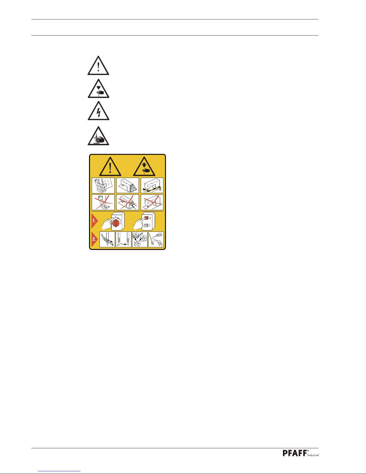
1.03 Safety symbols
Hazard point!
Special points of attention.
Risk of injury to operating personnel or technical staff!
Electric voltage!
Danger to operating personnel or technical staff
Danger of hands being crushed!
Danger to operating personnel or technical staff
Caution!
Do not operate without fi nger guard and safety covers!
Turn off the main switch before threading, changing the
bobbin or needle, cleaning, etc.!
1.04 Special points of attention for the owner-operator
This instruction manual is a part of the machine and must be made available to the
operating personnel at all times. The instruction manual must have been read before the
initial start-up.
The operating personnel and technical staff must be instructed about the machine's
safety covers and about safe working methods.
The owner-operator may only operate the machine in a fl awless condition.
The owner-operator must ensure that no safety covers are removed or disabled.
The owner-operator must ensure that only authorised persons work on the machine.
Additional information can be requested from the responsible sales centre.
I
Page 9

Safety
9
1.05 Operating personnel and technical staff
1
.05.01 Operating personnel
Operating personnel are persons responsible for equipping, operating and cleaning the
machine and for fault clearance in the sewing area.
The operating personnel are obligated to comply with the following points:
The safety instructions provided in the instruction manual must be followed for all work!
Any work method jeopardising machine safety must be refrained from!
Tight-fi tting clothing must be worn. The wearing of jewellery such as chains and rings is
prohibited!
Care must be taken to ensure that no unauthorised persons are located in the machine's
hazard zone!
Any changes occurring on the machine which impair its safety must be reported to the
owner-operator immediately!
1.05.02 Technical staff
Technical staff are persons with technical training in electricity/electronics and mechanics.
They are responsible for lubricating, servicing, repairing and adjusting the machine.
The technical staff are obligated to comply with the following points:
The safety instructions provided in the instruction manual must be followed for all work!
Turn off the main switch and secure it against reactivation before starting any adjustment
and repair work!
Never work on live parts and equipment!
Exceptions are regulated by the EN 50110 standards.
Reattach the safety covers following repair and maintenance work!
Page 10
Safety
10
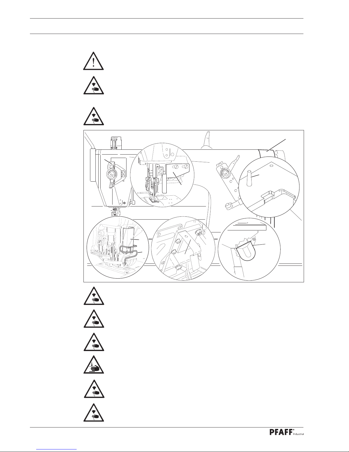
5
Fig. 1 - 01
4
1
7
2
7
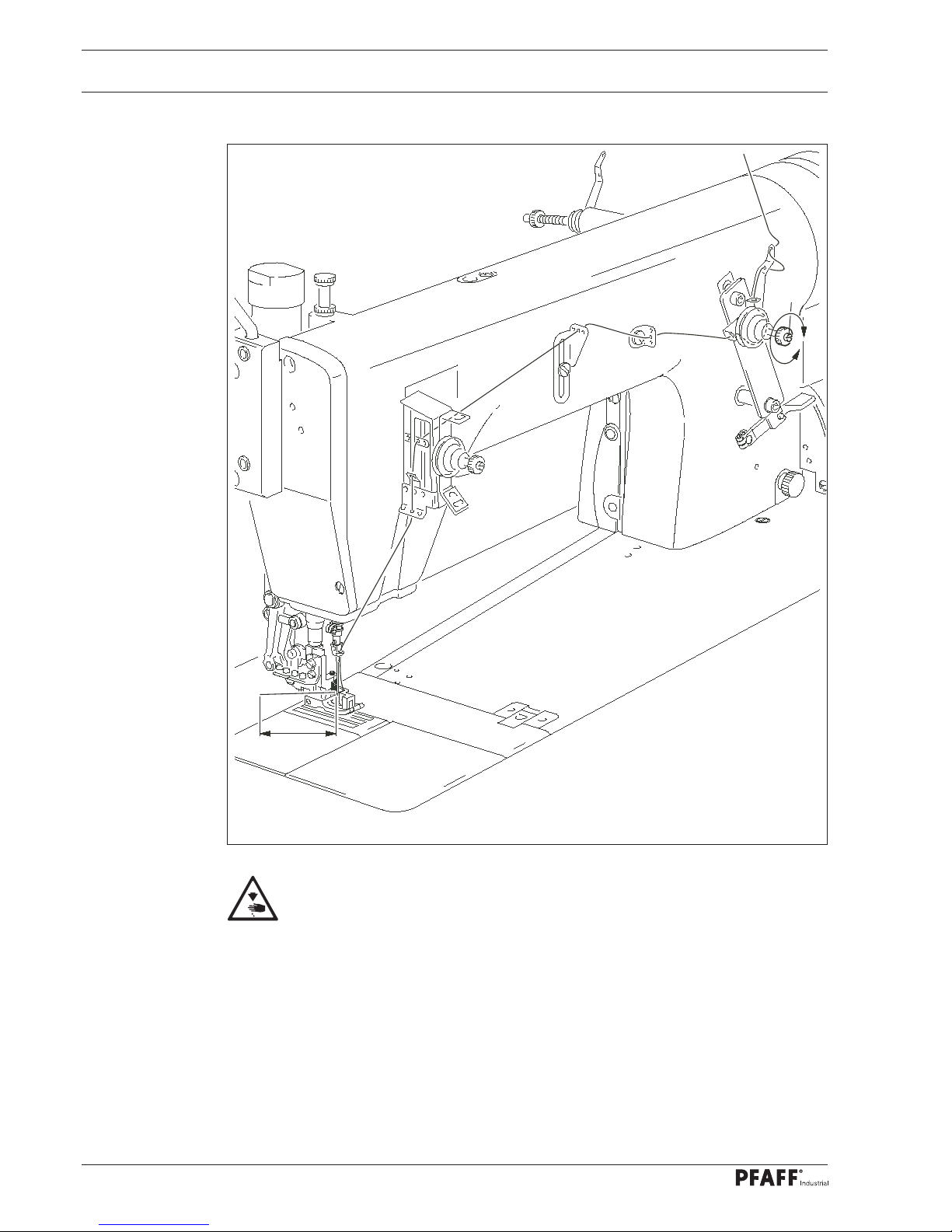
1.06 Danger warnings
A work area of 1 m must be kept free in front of and behind the machine during
operation to ensure unobstructed access at all times.
Do not reach into the needle range during the sewing operation!
Risk of injury from the needle!
Do not allow any objects to be placed on the table during the adjustment work!
The objects could become jammed or be slung away!
Risk of injury from parts fl ying around!
Do not operate the machine without the take-up lever guard 1!
Risk of injury due to the motion of the take-up lever!
Do not operate the machine without the fi nger guard 2!
Risk of injury from the needle!
Do not operate the machine without the belt guard 3 and 4!
Risk of injury due to the rotating driving belt!
Do not operate the machine without the anti-tipping device 5!
Risk of injury from crushing between the sewing head and the table top!
Do not operate the machine without the support 6! Risk of damage due to the
top-heavy sewing head! Machine can tip over backwards when moving it!
Do not operate machines with edge trimmer without fi nger guard 7!
Do not reach into the cutting area between the needle plate and the blade!
Risk of injury due to the cutting motion of the blade!
6
3
Page 11

Proper Use
11 11
2 Proper Use
Proper Use
The PFAFF 3811-3/55 is an integrated work station that is used in the shoe industry for the
incorporation of fullness into one material layer.
The PFAFF 3811-15/65 is an integrated work station that is used in the upholstery industry
for the incorporation of fullness into one material layer.
The PFAFF 3811-16/65 is an integrated work station that is used in the upholstery industry
for the incorporation of fullness into one material layer while simultaneously trimming the
material edge.
Any usage not approved by the manufacturer is deemed misuse!
The manufacturer shall assume no liability for damage caused by misuse!
Proper use also includes compliance with the operating, maintenance,
adjustment and repair measures specifi ed by the manufacturer!
Page 12

Technical Data
12
3 Technical Data
3.01 PFAFF 3811
Stitch type: .......................................................................................... 401 (Double chainstitch)
Needle system:
3811-15/65; 3811-16/65: ............................................................................................... 4463-35
3811-3/55 ................................................................................................................... 4463-KKD
Needle size in 1/100 mm .............................................................................................. 80 - 110
Basic stitch length:
3811-3/55 .......................................................................................................................2.2 mm
3811-15/65; 3811-16/65: ........................................................................................3.0 - 4.0 mm
Differential feed - feed motion
3811-3/55 ...............................................................................................................2.2 - 6.5 mm
3811-15/65; 3811-16/65: ........................................................................................4.0 - 8.0 mm
Speed max.: ............................................................................................... 3200 stitches/min
Clearance beneath the presser foot:
3811-3/55 ..........................................................................................................................7 mm
3811-15/65; 3811-16/65: ...................................................................................................1 mm
Sewing head dimensions
Length: ........................................................................................................... approx. 1250 mm
Width: ..............................................................................................................approx. 600 mm
Height (with spool holder): ............................................................................. approx. 1700 mm
Working air pressure: ......................................................................................................... 6 bar
Air consumption: .................................................................................... 0,3 - 0,5 l / work cycle
Connection data:
Operating voltage: ...............................................................................230 V ± 10 %, 50/60 Hz
Max. input power: ...........................................................................................................400 VA
Fuse protection: ...................................................................................................1 x 16 A, inert
Noise data:
Emissions sound pressure level in the workplace at n = 2600 min-1: .............. LpA = 79 dB(A)
(Noise measurement in accordance with DIN 45 635-48-A-1,
ISO 11204, ISO 3744, ISO 4871)
Net weight: .......................................................................................................... approx. 97 kg
Gross weight: .................................................................................................... approx. 132 kg
Subject to alterations
Depending on the material, workstep and stitch length
KpA = 2,5 dB
Page 13

Disposal of the Machine
13
4 Disposal of the Machine
It is up to the customer to dispose of the machine properly.
The materials used for the machine include steel, aluminium, brass and various plastics.
The electrical equipment consists of plastics and copper.
The machine must be disposed of in accordance with the locally valid environmental
protection regulations, with a specialised company being contracted if necessary.
Please ensure that parts coated with lubricants are disposed of separately in
accordance with the locally valid environmental protection regulations!
Page 14

Transportation, Packaging and Storage
14
5 Transportation, Packaging and Storage
5
.01 Transport to the customer's premises
All machines are completely packed for delivery.
5.02 Transportation within the customer's premises
The manufacturer assumes no liability for transport within the customer's premises or to
the individual usage sites. Please ensure that the machines are only transported in a vertical
position.
5.03 Disposal of the packaging materials
The packaging materials of these machines consists of paper, cardboard and VCI fl eece.
It is up to the customer to dispose of the packaging properly.
5.04 Storage
The machine can be stored for up to 6 months when not in use. It must then be protected
from dirt and moisture. For longer storage periods, the machine's single components, espe-
cially its sliding surfaces, must be protected against corrosion, e.g. by an oil fi lm.
Page 15

Work Symbols
15
6 Work Symbols
Activities to be performed or important information in this instruction manual are
emphasised by symbols. The symbols used have the following meaning:
Note, information
Cleaning, care
Lubrication
Maintenance, repairs, adjustment, service work
(only to be carried out by technical staff)
Page 16
Operating Controls
16
7 Operating Controls
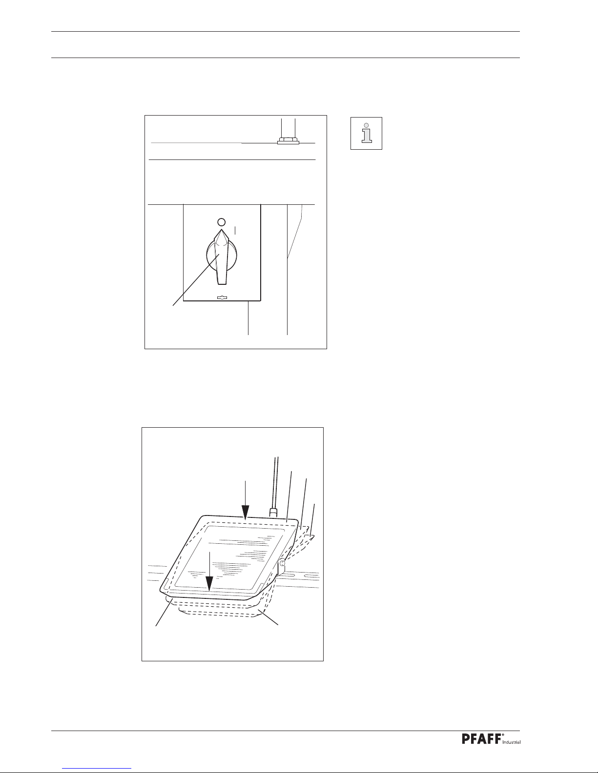
7
.01 Main switch
Before switching on the ma-
chine, raise the take-up lever as
far as possible.
Turning the main switch 1 switches the
machine on and off.
Fig. 7 - 01
1
7.02 Pedal
With the main switch turned on
0 = Neutral position
+1 = presser foot raised / feed
bridle tape
+2 = Sewing
1 = Raise presser foot
-2 = Thread trimming (Option)/
need up/edge knife off (if parameter 210 is at "ON", see
Chapter 13.07 Parameter
settings)
0
-2
-1
Fig. 7 - 02
+1
+2
Page 17
Operating Controls
17
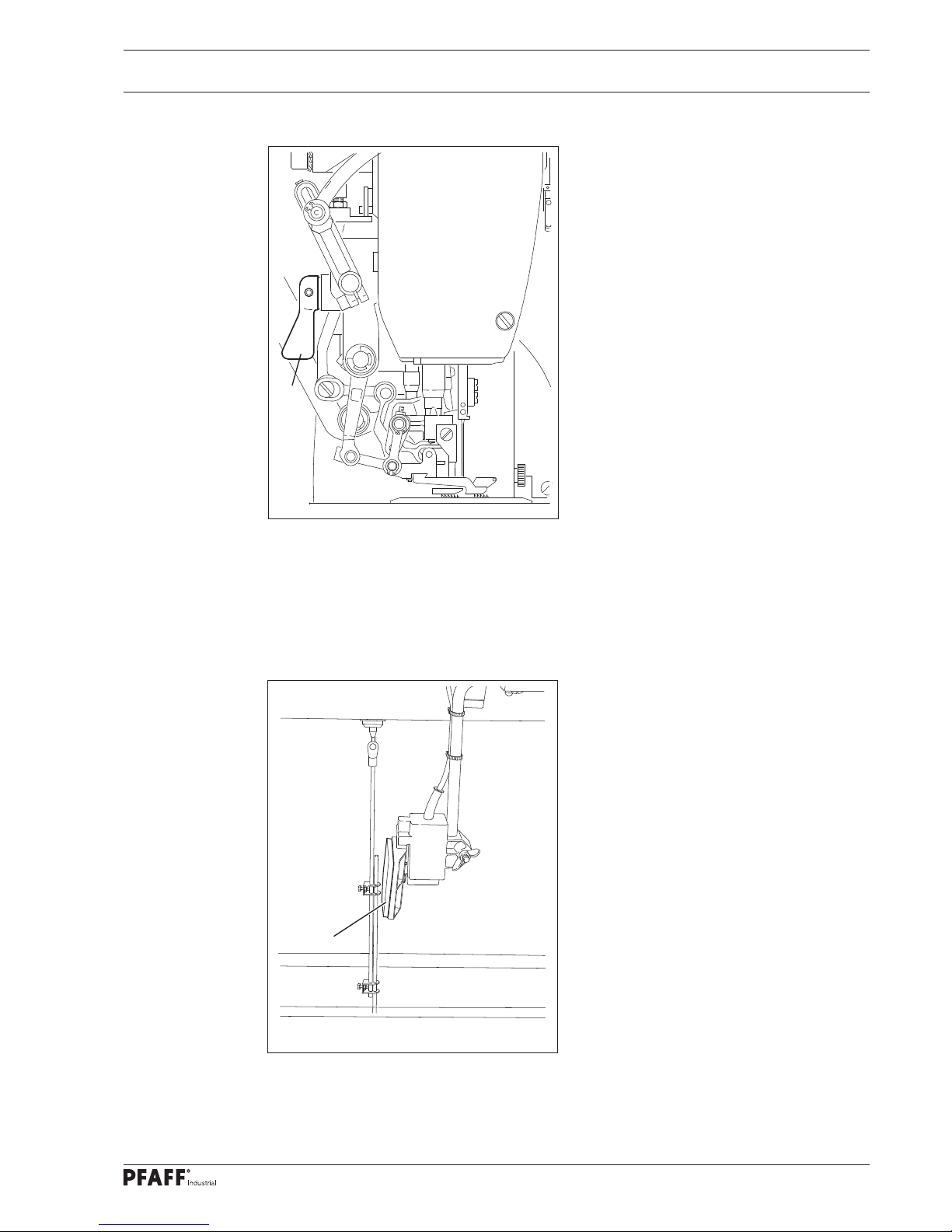
Fig. 7 - 03
7.03 Hand lever to raise the presser foot
Turning the hand lever 1 raises the
presser foot.
1
7.04 Knee switch
When sewing with fi xed programs:
Actuating the knee switch 1 switches
between two predefi ned fullness
settings
With programmed sewing:
By actuating the knee switch 1, the
fullness is switched according to the
program specifi cation.
Fig. 7 - 04
1
Page 18
Operating Controls
18
7.05 Edge guide (only with PFAFF 3811-3/55 and PFAFF 3811-15/65)
By pushing down lever 1 the edge guide
is switched on.
By lifting lever 1 the edge guide is
switched off.
1
Fig. 7 - 05
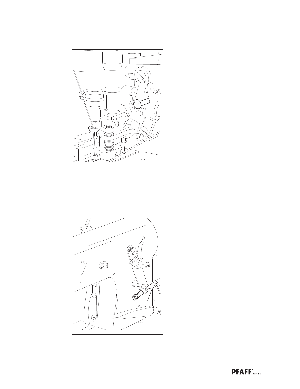
7.06 Lever for releasing thread tension
Press down lever 1 to release thread
tension.
Fig. 7 - 06
1
Page 19
Operating Controls
19
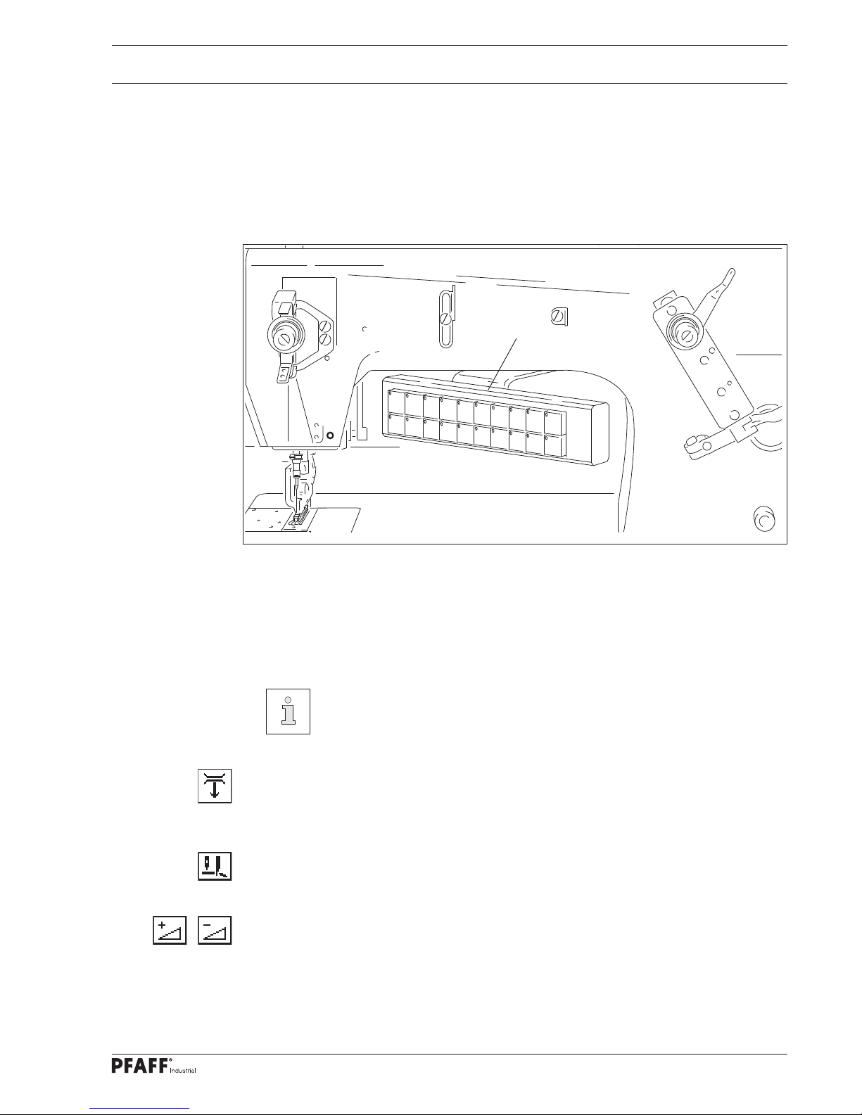
7.07 Keypad
Keypad 1 is used to quickly operate the machine during sewing. Each key can be assigned
an individual fullness value, see Chapter 9.05 Input fullness. By means of the respective
light-emitting diode of the 20 keys, activated key functions are displayed (function activated
= luminous diode).
Fig. 7 - 07
Numeric keys (0 - 15)
The pre-assigned fullness value is retrieved by pressing the key.
The corresponding average value is called by pressing two adjacent numeric keys at the
same time.
In the basic setting of the keypad, the set range is divided into 15 sub-steps
from "0" to "max." The basic setting is e.g. after a cold start, see Chapter 13.13
Cold start.
Tape brake (option)
The tape brake is switched on or off by pressing the key.
When the belt brake is engaged, the gathering of the material is enhanced.
Edge trimmer
The edge trimmer device is switched on or off by pushing the key.
Correction value +/correction value -
By pressing the key the value for the multiple width is increased or decreased by 2
steps.
1
9
3
8
7
5
1
6
2
4
0
1
1
1
2
1
3
1
4
1
5
1
0
1
1
Page 20

Operating Controls
20
Fig. 7 - 08
2 GB
max.
7.08 Control panel
The current operating statuses are indicated on the control panel 1. The machine
is operated with constant dialogue between the control unit and the operator; different
pictograms and / or texts are displayed for this purpose according to the operating status of
the machine. Pictograms or texts with a border represent
functions that can be called up by pressing on the respective point on the monitor. Pressing
the respective function causes its immediate actuation or activation/deactivation or another
menu will appear, e.g. for entering a value. Activated functions are indicated by pictograms
shown inversely. Apart from the bobbin change function, the pictograms and texts without
border are only for display purposes and cannot be called up by pressing them.
SD card 2 in the control panel can be used to import seam programs.
Presentation of functions
Normal pictogram = Function deactivated (inactive)
Inverse pictogram = Function activated (active)
1
2
Page 21
Set-up and Initial Start-up
21
8 Set-up and Initial Start-up
The machine may only be set up and started up by qualifi ed personnel! All of
the relevant safety regulations must always be complied with in this process!
If the machine was delivered without a table, then the stand and the table top
provided must safely support the weight of the machine and its motor.
Adequate stability of the stand must be guaranteed, even during the sewing
operations.
8.01 Set-up
Suitable electrical supply connections must be provided at the erection site, see Chapter 3
Technical data. The erection site must also have a fi rm and level subsurface and adequate
lighting.
The table top is lowered for packaging purposes.
The adjustment of the table height is described below.
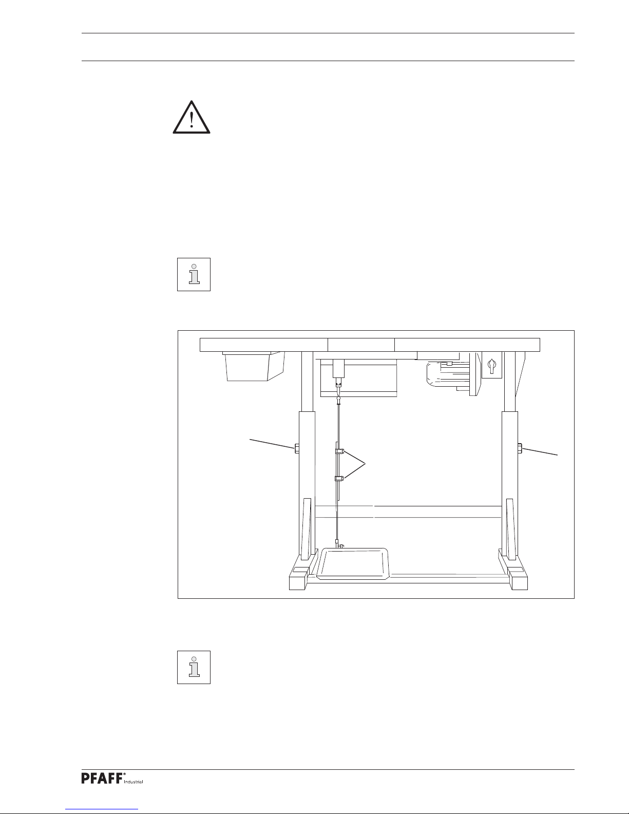
8.01.01 Setting the table height
Fig. 8 - 01
Loosen the screws 1 and 2
Move the table top to the desired working height by pulling it out and pushing it in and
align the table top horizontally.
Adjust the stand on both sides evenly to prevent it tilting.
The stand must have all four feet fi rmly on the ground to make sure it is positioned
securely.
Firmly tighten the screw 1.
Adjust and tighten the desired pedal position on the screws 2.
1
1
2
Page 22
Set-up and Initial Start-up
22
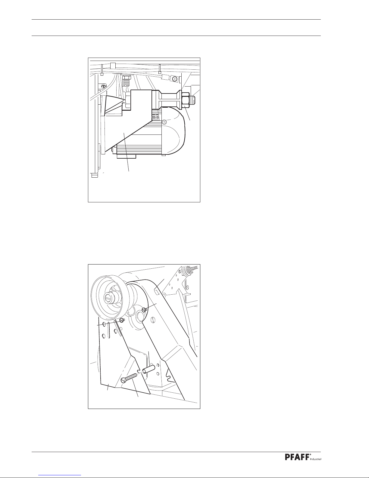
8.01.02 Tension v-belt
Fit the V-belt.
Loosen the nut 1 and tension the V-belt
by turning the motor bracket 2 out of po-
sition.
Tighten nut 1.
Fig. 8 - 02
2
1
8.01.03 Mounting the upper V-belt guard
Screw in screws 1 and 2.
Screw in screw 3 together with spacing
bush 4.
Slide belt guard halves 5 with their slots
behind the heads of the screws 1 and 3.
Gently tighten screw 1 .
Take note that the lug of the belt guard
half 6 is located between belt guard half
5 and spacing bush 4, align the complete
belt guard and tighten screws 1, 2 and 3.
Fig. 8 - 03
5
1
2
3
6
4
Page 23

Set-up and Initial Start-up
23
Fig. 8 - 04
Loosen screws 2 and align the belt guard bracket 1 so that the motor pulley and v-belt
run freely.
Tighten screws 2.
Secure the belt guard 3 with screw 4
1
2
2
4
3
8
.01.04 Mounting the lower V-belt pulley
Fig. 8 - 05
8.01.05 Fitting the position sensor
Attach the position fi nger 1 with the
screws 2.
Slide the synchroniser 3 onto the shaft
so that the position fi nger 1 is positioned
in the groove of the synchroniser 3, see
arrow.
Gently tighten the screws 4.
Insert the synchroniser plug on the fe-
male coupling of the control box.
Set synchroniser 3, see Chapter
13.05.01 Home position of the machine.
1
2
3
4
Page 24
Set-up and Initial Start-up
24
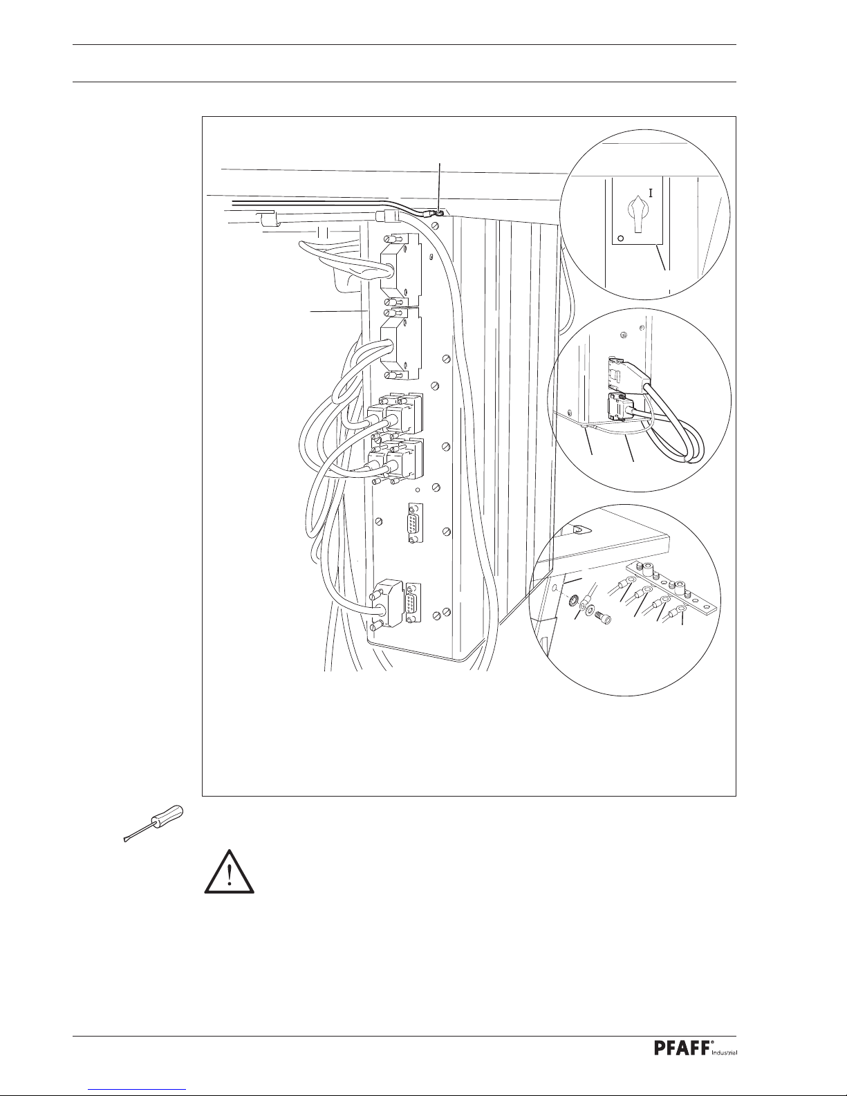
8.01.06 Connecting the plug-in connections and ground cable
Insert all plugs on the control box 1 in accordance with their designation.
Insert the "motor" into the bushing X 3 and the bushing X 8.
Caution
Inserting the plug incorrectly can damage the control unit!
Attach the following ground cables in order to discharge static electricity
Securely attach ground cable from sewing head to ground point A.
Securely attach the ground cable from the control point B to ground point B.
Securely attach the ground cable from the main switch 3 to ground point C.
Securely attach the ground cable from the stand 4 to ground point D.
Securely attach the ground cable 5 from the motor to ground point E.
5
E
A
B
C
D
4
D
1
Fig. 8 - 06
B
0
3
Page 25
Set-up and Initial Start-up
25
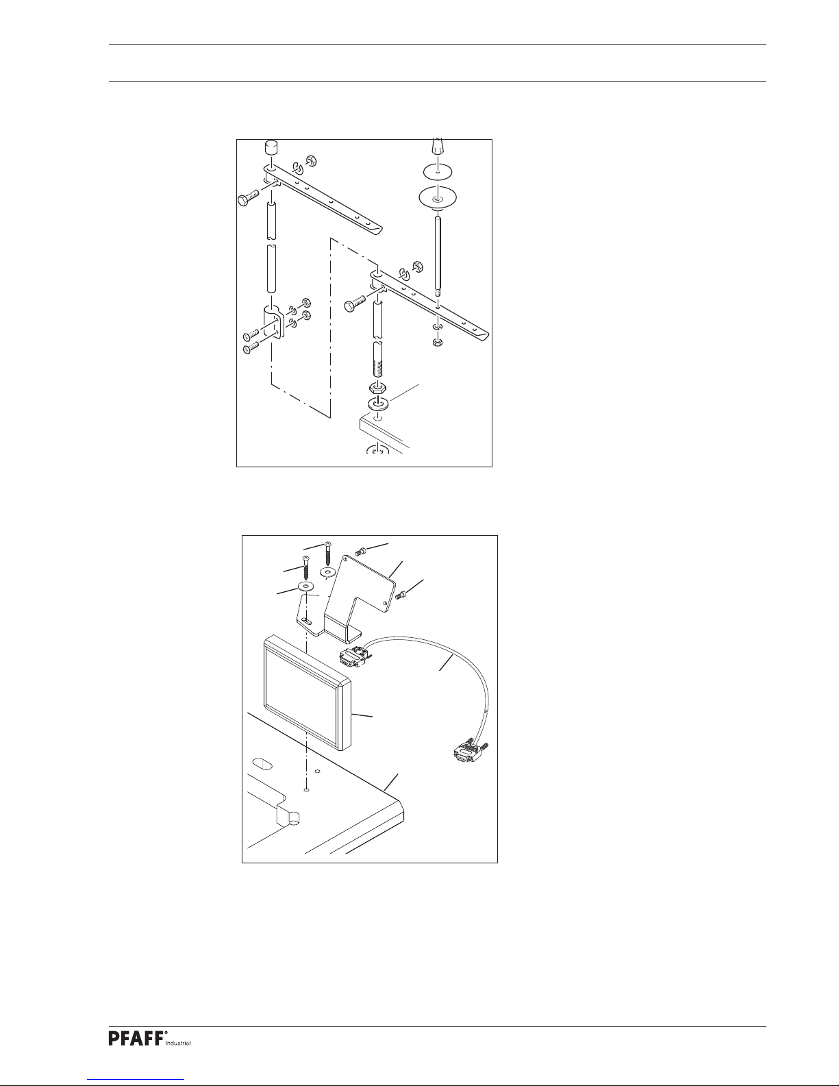
8.01.07 Assembling the reel stand
Assemble the reel stand as shown in the
adjacent illustration.
Then insert the stand into the
hole in the table top and secure it with
the enclosed nuts.
Fig. 8 - 07
8.01.08 Mounting the control panel on the table top
Mount control panel bracket 1 on table
plate 4 with screws 2 and washers 3.
Screw control panel 5 to control panel
bracket 1 with screws 6.
Connect the connecting cable 7 to the
control unit together with the control
panel 5 and the provided plug-in
connection.
Fig. 8 - 08
1
2
3
X1/A
2
3
5
4
A2
6
7
6
Page 26
Set-up and Initial Start-up
26
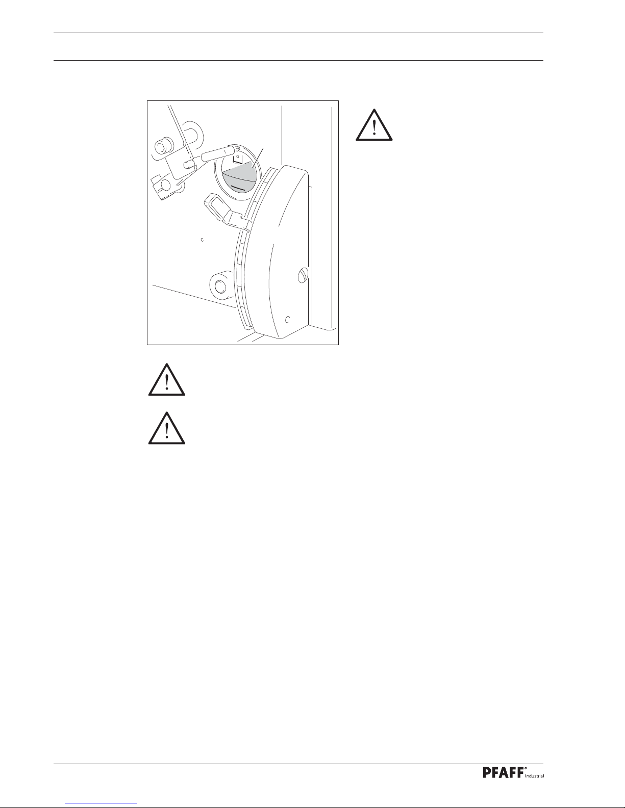
8.02 Initial commissioning
Before initial commissioning,
remove the protective fi lm from
the sight glass 1.
Clean the machine thoroughly and then
check the oil level, see Chapter 12
Maintenance and Care.
Inspect the machine, particularly the
electric cable, for any damage.
Arrange for technical staff to check
whether the machine's motor may be
operated at the existing mains voltage
and whether it is connected properly.
Never operate the machine if there are any differences.
The machine must only be connected to a grounded socket!
With the machine running, the handwheel must turn towards the operator, otherwise ar-
range for technical staff to adjust the motor, see Chapter 13.07 Parameter settings.
For machines with pneumatic devices, the machine must be connected to the
compressed air system. The manometer should show a pressure of 6 bar. Or set this
value (see Chapter 12.04 Checking/setting the air pressure).
8.03 Switching the machine on/off
Switch machine on and off (see Chapter 7.01 Main switch).
Perform test run
Fig. 8 - 09
1
Page 27
Set-up
27
9 Set-up
Observe and comply with all regulations and instructions in this instruction
manual.
Pay particular attention to all safety regulations!
All set-up work may only be carried out by appropriately instructed personnel.
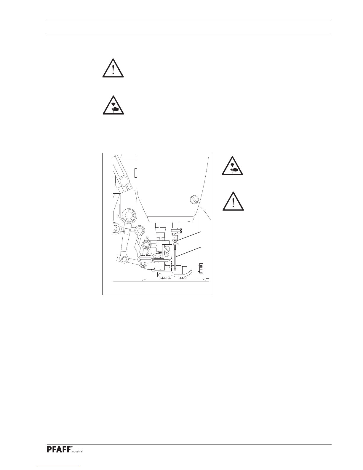
Disconnect the machine from the electricity mains for all set-up work by operat-
ing the main switch or by removing the mains plug!
Switch off the machine!
Risk of injury due to accidental
machine start-up!
Only use needles of the system
intended for the machine, see
Chapter 3 Technical Data!
9.01 Inserting the needle
Bring the needle bar to the top position.
Loosen the screw 1 and insert the nee-
dle 2 until you feel it stop. The long
groove must point forwards.
Tighten the screw 1.
Fig. 9 - 01
2
1
Page 28
Set-up
28
9.02 Threading the needle/adjusting the needle thread
Switch off the machine!
Risk of injury due to accidental machine start-up!
Thread the needle as shown in Fig. 9-02.
Adjust the needle thread tension by turning the knurled thumb screw 1.
1
+
-
Fig. 9 - 02
approx. 7 cm
Page 29
Set-up
29
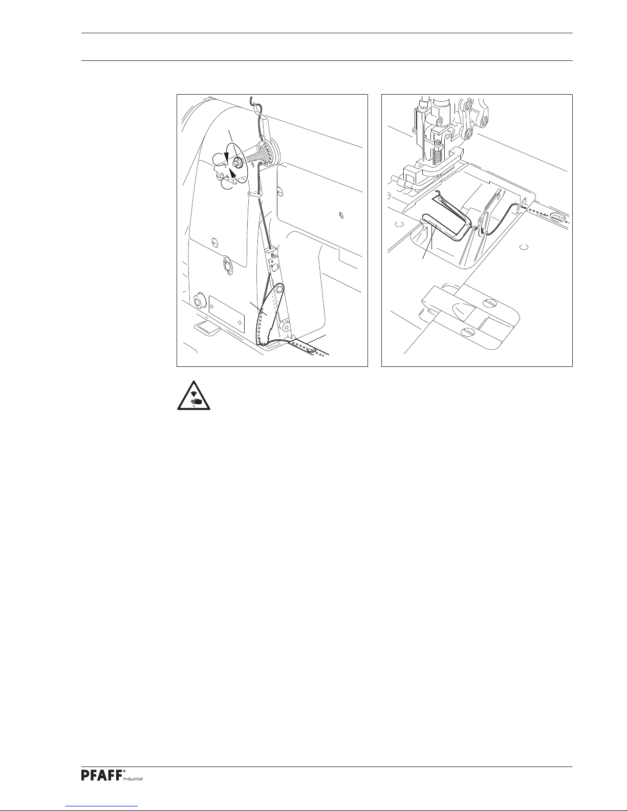
9.03 Threading the looper thread/adjusting the looper thread
Fig. 9 - 03
Switch off the machine!
Risk of injury due to accidental machine start-up!
Open the looper compartment cover and swing out the thread guide plate1.
Thread the looper thread according to Fig. 9-03 and 9 - 09 and pull it under guide plate 2.
Use tweezers 3 to thread in the looper.
Adjust the looper thread tension by turning the knurled thumb screw 4.
4
1
2
-
+
Fig. 9 - 04
3
Page 30
Set-up
30
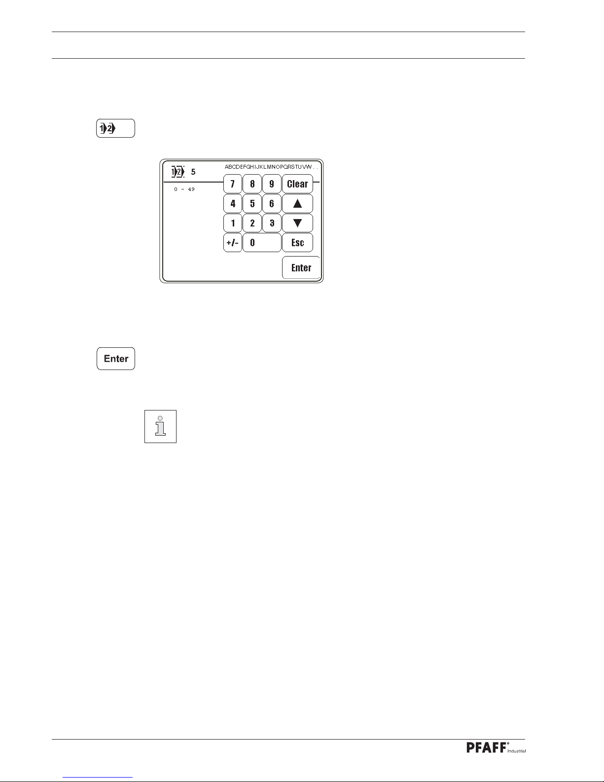
9.04 Selecting program numbers
Switch the machine on.
Call up the menu to input the program number.
Select the desired program number.
Confi rm the selection and leave the selection menu.
The selection of the program number determines the type of sewing, see
Chapter 10 Sewing.
Program number 0: Manual sewing
Program numbers 1 and 2: Sewing with fi xed programs
Program numbers 3 to 49: Programmed sewing
Page 31

Set-up
31
9.05 Inputting fullness
Switch the machine on.
Call up the menu to input the program number.
Select program number "0".
Confi rm the selection and leave the selection menu.
Enter the desired value using the corresponding arrow keys.
Or enter the current fullness value of a numeric key (0 - 15) of the keypad.
To do this, press and hold down the desired key until a sound is heard.
Fig. 9 - 05
9
3
8
7
5
1
6
2
4
0
1
1
1
2
1
3
1
4
1
5
1
0
1
1
Page 32

Set-up
32
9.06 Entering/changing the template code
Switch the machine on.
Call up “Input” mode.
Call up parameter '800'.
Call up the code number input menu.
Enter the code number using the numeric keypad (code set at the factory is"3800").
Page 33

Set-up
33
Adopt input code number
Call up parameter '810'.
Call up the input menu for the code number and enter the desired code number.
Adopt new code number.
Conclude input.
The code input remains saved until the machine is switched off by the main
switch. Provided that the machine is not turned off, all parameters can be
accessed without re-entering the template code.
Remember the code!
Protected functions cannot be called up without the corresponding code!
In this case request support from the PFAFF service centre.
Page 34

Set-up
34
9.07 Setting the control panel
Switch the machine on.
Call up “Input” mode.
Call up the service menu.
Call up the control panel functions.
Change the display contrast.
Switch the key tone off or on.
Never reduce the display contrast to such an extent that the display can no
longer be read!
Page 35

Sewing
35
10 Sewing
In sewing mode, all settings relevant to the sewing process are shown on the display and
can be altered there directly using the corresponding function.
In the sewing mode a difference must be made between manual sewing, sewing with fi xed
programs and programmed sewing.
The selection is made by selecting the corresponding program number:
0: Manual sewing
1 and 2: Sewing with fi xed programs
3 to 49: Programmed sewing
(with up to 15 seam zones for left and right seams)
10.01 Manual sewing
In manual sewing, the values for the width and the target stitching position are displayed on
the control panel during sewing and can be changed directly by means of the corresponding
function, such as the functions at the seam end, the material type as well as the needle and
foot positions.
Switch on the machine and select the program number "0", see Chapter 9.04 Selecting
program number
Description of the functions
Program selection
Opens the menu for inputting the program number, see chapter 9.04 Selecting a program
number.
Input mode
Quit the sewing mode and call up the input mode.
Fullness
Changes the value for the fullness, see Chapter 9.05 Input fullness.
Material type
The functions are used to select the material type, see Chapter 10.01.02 Selecting the material type.
Needle raised
Positions the needle in the top position.
Page 36

Sewing
36
10.01.01 Selecting material type
In order to obtain the same results (multiple widths) during the processing of different materials, you can select between 3 types of material at any time in Manual Sewing and when
working with fi xed programs:
Material type light (here without quilting)
Material type medium (here without quilting)
Material type heavy (here without quilting)
The icon of the currently selected material type is displayed inversely.
For each material type, 4 different quilting levels can be selected. To do this, the symbol of
the corresponding material type has to be pressed until the appropriate fullness level ap-
pears in the display:
without quilting
approx. 80 g/m² quilting
approx. 200 g/m² quilting
approx. 400 g/m² quilting
Needle position raised
If this function is on, the needle moves to top position when sewing stops.
Thread trimming
- When the function is activated, thread trimming with the pedal function is possible
(optional).
- When switched on this function enables the edge knife to be switched off via pedal
function, see Chapter 7.02 Pedal.
Presser foot up
When this function is activated, the presser foot is raised after sewing stops.
Presser foot down after the edge knife is turned off
When the function is switched on, the presser foot is not raised after the edge knife has
been switched off.
Sewing is carried out using the pedal function, see Chapter 7.02 Pedal .
Page 37

Sewing
37
10.02 Sewing with fi xed programs
Fixed programs are set under the program numbers 1 and 2.
The fi xed programs are are used for the quick and easy sewing of seams with different fullness. When sewing with fi xed programs, 2 or 3 seam areas are processed one after the oth-
er. The advance seam zone is effected by actuating the knee switch. The fi xed programs
are designed as concentric programs, meaning after the end of the last seam zone, the
fi rst seam area is started again. The value for the multiple width can be set for each seam
zone, the settings for the target stitch position as well as the needle and foot positions apply
across the entire area and can be changed at any time via the corresponding function.
Switch on the machine and select the program number "1" or "2", see Chapter 9.04 Se-
lecting program number
Explanation of the displays and functions
Program selection
Opens the menu for inputting the program number, see chapter 9.04 Selecting a program
number.
Seam zone
Displays the number of seams of the sewing program.
Input mode
Quit the sewing mode and call up the input mode.
Fullness
Changes the value for the fullness, see Chapter 9.05 Input fullness.
Material type
The functions are used to select the material type, see Chapter 10.01.02 Selecting the
material type.
Needle raised
Positions the needle in the top position.
Page 38

Sewing
38
Needle position raised
If this function is on, the needle moves to top position when sewing stops.
Thread trimming
- When the function is activated, thread trimming with the pedal function is possible
(optional).
- When switched on this function enables the edge knife to be switched off via pedal
function, see Chapter 7.02 Pedal.
Presser foot up
When this function is activated, the presser foot is raised after sewing stops.
Presser foot down after the edge knife is turned off
When the function is switched on, the presser foot is not raised after the edge knife has
been switched off.
Sewing is performed using the pedal and knee switch functions, see Chapter 7.02 Ped-
al or 7.04 Knee switch.
Page 39

Sewing
39
10.03 Programmed sewing
Pre-programmed seams can be called up via program numbers 3 - 49.
In the programmed sewing mode all seam zones are set in a seam program. The information
on the seam program, such as the program number, the number of programmed seam
zones, and the programmed comment are displayed. For easier orientation, a seam sketch
with the programmed seam areas is shown. The seam start, the seam end, the already
processed seam zones, the current seam zone and the seam zones still to be sewn are
indicated by symbols and different line types and line thicknesses. The respective seam
zone number parameter, fullness and the functions at the seam end are displayed for the
current seam zone. The material type can be changed directly as well as other functions.
Switch on the machine and select the required program number "3" to "49", see Chapter
9.04 Selecting program number
Explanation of the displays and functions
Program selection
Opens the menu for inputting the program number, see chapter 9.04 Selecting a program
number.
Seam zones right/left
Displays the number of seam zones of the seam program for the right/left seam.
Input mode
Quit the sewing mode and call up the input mode.
Fullness
Displays the current value for the fullness.
Current seam zone
Displays the current seam zone.
Page 40

Sewing
40
Current seam
Serves for selecting and displaying the current seam (right/left).
Automatic seam change
Switches automatically between the right and the left seam with this function switched on.
Material type
The functions are used to select the material type, see Chapter 10.01.02 Selecting the material type.
Needle raised
Positions the needle in the top position.
Program interrupt
Interrupts the seam program sequence, see chapter 10.03.01 Program interruption.
Thread trimming
- When the function is activated, thread trimming with the pedal function is possible
(optional).
- When switched on this function enables the edge knife to be switched off via pedal
function, see Chapter 7.02 Pedal.
Presser foot up
When this function is activated, the presser foot is raised after sewing stops.
Presser foot down after thread trimming
When this function is activated, the presser foot is not raised after thread trimming.
Sewing is carried out using the pedal and knee switch function, see Chapter 7.02 Pedal .
Page 41

Sewing
41
10.03.01 Program interruption
The "program interruption" function is used to interrupt the programmed seam sequence
(e.g., in the case of a thread break).
Interrupt program sequence
Or sequence program forwards and backwards.
Or change values and perform the other functions as in manual sewing, see Chapter
10.01 Manual sewing.
Or call up manual sewing.
10.04 Error messages
If an error occurs, the text "ERROR" appears on the display, together with an error code. An
error message is generated by incorrect settings, faulty elements or seam programs, as well
as overloading.
For an explanation of the error codes, see chapter 13.09 Explanation of error messages.
Correct the error.
Acknowledge the elimination of the error.
Page 42

Input
42
11 Input
The functions Parameter input, Info, Sewing program set/correct, Teach-in, Program
management and Service are available In the operating mode Input.
Switch the machine on.
Call up “Input” mode.
Description of the functions
Sewing mode
Quit the input mode and call up the sewing mode.
Parameter selection
Select the hundred and unit fi gures of the desired parameters, see chapter 13.07.02
Example of a parameter input.
Altering the parameter value
Change the value of the selected parameter, see chapter 13.07.02 Example of a
parameter input.
Software information
Calls up information about the current machine software.
Create/correct program
Opens the menu for input or change seam programs, see Chapter 11.01.02 Seam program
input via the function “Program set/correct”
Teach In
Opens the menu for inputting seam programs by stitching a sewing sample, see Chapter
11.01.04 Seam program input via the function “Teach- in”.
Program management
Opens the menu managing sewing programs, see Chapter 11.03 Managing seam
programs.
Service
Opens the service menu, see Chapter 13.12 Service menu.
Page 43

Input
43
11.01 Entering seam programs
Seam programs can be created by inputting parameters in the function “Create / correct
seam programs” or sewing a seam sample with the “Teach in” function. Irrespective of
which function is changed, the program number and basic settings of the sewing program
to be processed must fi rst be selected.
11.01.01 Basic settings for seam program input
The basic settings are the same in the functions “Create/correct program” and “Teach in”.
Switch the machine on.
Call up “Input” mode.
Call up the function “Create / correct seam program” and “Teach in”.
Or change the selected program number and confi rm the selection.
Or input or change a comment.
Page 44

Input
44
Defi ne the type of seam (by pressing the corresponding symbol multiple times until the
respective type of seam is displayed).
Explanation of symbols:
Sewing program with left and right seam, beginning with right seam
Sewing program only with left seam
Sewing program only with right seam
Sewing program with left and right seam, beginning with left seam
End the input the basic settings and change to the input of the seam zone, see Chapter
11.01.02 input via the “Create/correct program” function or Chapter 11.01.04 Seam
program input via the “Teach in” function.
The input can also be completed by calling up the sewing mode. This function
is used to conclude the seam program input and the machine switches to the
programmed sewing mode.
Page 45

Input
45
11.01.02 Seam program input via the function "Create/correct program"
This function is used to enter the seam program by entering or changing the corresponding
values on the keypad. This type of seam program input is particularly suitable for correcting
already existing seam programs.
Switch the machine on.
Call up “Input” mode.
Call up the function “Create/correct seam program”.
Make basic settings and complete with the "Enter" function, see Chapter 11.01.01 Basic
settings for seam program input
Change the actual are set length of the seam, see Chapter 11.01.03 Entering the actual
and actual length of the seam zone
Change the fullness setting, see Chapter 9.05 Entering fullness setting
Change the maximum speed for the current seam zone.
The functions are rolled by the current seam program.
The current seam zone is displayed alongside all other current values.
Enter the functions for the end of the seam zone, see Chapter 11.01.05 Seam zone
input when programming the seam
Select seam type.
The selection by left and right seam is only possible if the seam type “left and right
seam” is selected in the basic settings, see Chapter 11.01.01 Basic settings for seam
program input.
Page 46

Input
46
Or insert the seam zone.
The current seam zone is copied and all subsequent seam zones are set backwards.
Or delete the current seam zone.
Or end the current seam entry and save the parameters in reverse order for the other
seam (mirroring).
Defi ne seam or programming end.
When entering, the program the end of a seam is set in the desired seam zone.
Analogous to the end of the program, the seam end is set when entering the right and
left seam. The seam end is set in the fi rst seam and the program end is set in the sec-
ond seam.
Complete the fi rst seam zone and change to the next seam zone.
End input and change to the input of the basic settings.
End the input and change to programmed sewing.
11.01.03 Entering the actual and target length of the seam zone
After calling the corresponding function, the menu for entering the values for the seam
length (in mm) of the current seam zone appears. After entering the values for the actual
and target length, the stitch count and the fullness settings are calculated. A later change in
the fullness setting or the number of stitches also changes the values for actual and target
length.
Change value for actual length (via numeric input or via arrow keys).
Change value for target length (via numeric input or via arrow keys).
Conclude the input.
Page 47

Input
47
11.01.04 Seam program input via the function "Teach In"
This function is used to create the seam program by sewing a sewing pattern. A new crea-
tion is always made, meaning that when selecting an already existing program it is overwrit-
ten.
Switch the machine on.
Call up “Input” mode.
Call up "Teach In" function.
Make basic settings and complete with the "Enter" function, see Chapter 11.01.01 Basic
settings for seam program input
The following displays and functions appear on the display before sewing:
Input the fullness setting, see Chapter 9.05 Entering fullness setting
Input the maximum speed for the current seam zone.
Use the pedal to sew the fi rst seam zone.
The number of stitches in the current seam zone is counted and shown in the display.
1
Page 48

Input
48
After sewing, the following information and functions appear on the display:
Pressing the Enter key defi nes the seam zone by stitch counting.
Actuating the pedal in position “2” executes the end of the seam zone by actuating the
pedal, see Chapter 7.02 Pedal
Actuating the knee switch executes the end of the seam zone by actuating the knee
switch, see Chapter 7.04 knee switch
After calling the function, further inputs for the end of the seam zone can be performed
and erroneous inputs corrected, see Chapter 11.01.05 Seam zone input when pro-
gramming the seam.
A stitch condensation is defi ned when entering the functions for the end of the
seam zone is performed on completion of the seam program entry. Up to 30
stitches are sewn. Risk of injury in the vicinity of the needle.
Defi ne seam or programming end.
When entering, the program the end of a seam (only left or right) is set in the desired
seam zone.
Analogous to the end of the program, the seam end is set when entering the right and
left seam. The seam end is set in the fi rst seam and the program end is set in the sec-
ond seam.
Conclude the input.
End input and change to the input of the basic settings.
End the input and change to programmed sewing.
Page 49

Input
49
11.01.05 Seam zone input during seam programming
After calling up the corresponding function, the menu for inputting the functions and values
for the end of the seam zone without stitch concentration appears.
If necessary switch off stitch concentration.
Switch the seam zone relaying using the pedal function on and off.
Switch the seam zone relaying using the knee switch on and off.
Enter or change the number of stitches for the seam zone (via numeric input or by using
the arrow keys).
Activate or deactivate automatic sewing stop at the end of the seam zone.
Activate or deactivate the "Lift sewing foot " function, see Chapter 10.01 Manual
sewing.
Activate or deactivate the "Thread trimming" function, see Chapter 10.01 Manual
sewing.
Activate or deactivate the "Needle position up" function, see Chapter 10.01 Manual
sewing.
End the input and change to programmed sewing.
Not every combination of functions is adjustable.
All activated functions are displayed inversely.
Page 50

Input
50
11.02 Examples for setting seam program
11
.02.01 Example of seam program input using the function "Create/correct program"
The seam program to be created should
- contain 4 seam zones and
- saved under program number 4 with the comment “PROG”.
Switch the machine on.
Call up “Input” mode.
Enter the "Create/correct seam program" function and enter the program number "4".
Press the key until the corresponding symbol appears, set the sewing type (right seam).
Call the menu to enter the comment.
Enter "PROG" using the keypad and numeric keypad.
Conclude the comment input.
Switch to the input of seam zone 1.
Page 51

Input
51
The fi rst seam zone should
- be worked without a fullness setting,
- the end of the seam zone should be executed by the knee switch.
Enter value "0" for the fullness.
Call up the seam zone menu.
Enable the seam zone relaying via the knee switch.
Complete the input of the seam zone.
Change to the second seam zone.
In the second seam zone, a target length of 140 mm is to be used for an actual length of
242 mm.
Call up the menu for entering the target/actual length of the seam zone.
Page 52

Input
52
Enter value "242" for the actual length.
Enter value "140" for the target length.
Complete the entry of the target/actual length.
The number of stitches (“37”) and the value for the fullness setting (“70”)
are determined from the values entered. Since conversion must be based on
whole stitches, the value for the target length ("141") must deviate slightly from
the entered value.
Change to the third seam zone.
Page 53

Input
53
In the third seam zone, a target length of 160 mm is to be used for an actual length of
190 mm.
Call the menu for entering the target/actual length of the seam zone and enter the values
for target and actual length.
Complete the entry of the target/actual length.
Change to the fourth seam zone.
In seam zone four
- it should be worked without a fullness setting,
- the end of the seam zone should be executed by the pedal function.
- the functions “trim thread” and “lift sewing foot” should be enabled.
Enter value "0" for the fullness.
Call up the seam zone menu.
Enable the seam zone relaying via the pedal function.
Switch on the “trim thread” function
Switch on the “presser foot up” function
Conclude the entry.
Activate "End program" function.
Complete the input of the seam program and change to the programmed sewing.
Page 54

Input
54
Switch the machine on.
Call up “Input” mode.
Enter the "Teach In" function and enter the program number "11".
11.02.02 Example for seam program input via the function "Teach In"
The seam program to be created should
- consist of one seam,
- contain 10 seam zones and
- saved under program number 11 with the comment “TEACH”.
Sewing direction
Seam zone 1
Gather setting: 0
End of section: Knee switch
Seam zone 2
Gather setting: 17
Stitch count: 49
Seam zone 3
Gather setting: 38
Stitch count: 31
Seam zone 4
Gather setting: 62
Stitch count: 21
Seam zone 5
Gather setting: 15
Stitch count: 128
Seam zone 6
Gather setting: 62
Stitch count: 21
Seam zone 7
Gather setting: 38
Stitch count: 31
Seam zone 8
Gather setting: 17
Stitch count: 49
Seam zone 9
Gather setting: 0
End of section: Knee switch
Seam zone 10
Gather setting: 12
Seam end: Pedal
Page 55

Input
55
Set the sewing type (press until the corresponding symbol for the left or right seam
appears).
Call up the comment input menu.
Enter "TEACH" using the keypad and numeric keypad.
Conclude the comment input.
Switch to the input of seam zone 1.
The fi rst seam zone should be worked with
no gathering (value "0").
or value "0" with gathering.
Sew the fi rst seam zone using the pedal function.
Call up the seam zone menu.
Enable the seam zone relaying via the knee switch function.
Switch to the input of seam zone 2.
Page 56

Input
56
The second seam zone should be worked with gather setting “17”.
Enter value "17".
Sew the second seam zone using the pedal function.
Change to the third seam zone.
Inputs for the 3rd to 8th seam zones as described for zone 2 (observe the respective
values in the diagram) and sew the individual seam sections.
Change to the ninth seam zone.
Enter value "0" with gathering.
Sew the ninth seam zone using the pedal function.
Call up the seam zone menu.
Enable the seam zone relaying via the knee switch function.
Switch to the input of seam zone 10.
17
Page 57

Input
57
The tenth seam zone should be worked with gather setting “12”.
Enter value "12".
Sew the tenth seam zone using the pedal function.
Defi ne the end of the seam zone via the pedal position “- 2”, see Chapter 7.02 Pedal
Activate "End program" function.
Complete the input of the seam program and change to the programmed sewing.
12
Page 58

Input
58
11.03 Managing seam programs
The program management displays the contents of the machine memory in the left-hand
half of the screen and the SD card in the right-hand half of the screen, and is used to erase
and copy programs. The selected programs are displayed in red. If the MDAT function is
activated, the machine data of the machine can be set to be saved
to the SD card or loaded from the SD card. The Format function is used to format the SD
card. The individual operations are displayed in a dialogue
window in English. After inserting the SD card, it will take up to 20 s until the SD card is
recognised as inserted.
Switch the machine on.
Call up “Input” mode.
Call up program management.
SD card and machine memory are read.
Description of the functions
Input mode
Calls up the basic screen of input mode.
Sewing mode
Quit the input mode and call up the sewing mode.
Program selection
After calling up the program management, at least one seam program is always
marked. Use the arrow functions to select the desired sewing program.
A block of sewing programs can be marked with the * function and the arrow functions.
Pressing the *-function again turns off the block function.
Copy
Press the Copy key to copy the selected program to or from the SD card.
Delete
Press the Delete key to delete the selected programs.
Page 59

Input
59
Dialogue box
The dialogue box is used to communicate the current operation. If necessary, additional
keys are shown for answering questions.
Enter key
Approval for a program.
All key
Approval for one or all marked programs.
Esc key
Reject for one or all marked programs.
Next key
Reject a program.
Select machine data
After pressing MDAT, the machine data can be copied or deleted on the SD card.
Format the SD card
The SD card is formatted after pressing FORMAT. A prompt for confi rmation is displayed
before the SD card is formatted.
The card is completely formatted if it cannot be read. All programs and machine fi les in this
directory are deleted if it can be read and the directory \P3811 for 3811 exists.
If the directory \P3811 for the 3811 does not exist, only the directory is created.
This is to ensure that programs from other machines and other fi les are not lost.
ALL
Format
MDAT
Next
Page 60

Maintenance and Care
60
These maintenance intervals are based on an average running time of a single
shift production shop. Shorter maintenance intervals are recommended for
increased running times.
12.02 Cleaning the machine
The required cleaning cycle for the machine depends on the following factors:
Single or multi-shift operation
Dust formation caused by the workpieces
Optimal cleaning instructions can therefore only be determined on a case-by-case basis
Disconnect the machine from the electricity mains for all cleaning work by
shutting off the main switch or removing the mains plug! Risk of injury due to
accidental machine start-up!
The following tasks are recommended
during single shift operation to avoid
operational errors:
Tilt the machine backwards.
Clean the hooks and hook area daily or
more often during continuous operation.
When righting the sewing head, ensure
pressing the anti-tipping device 1.
Return the machine to its
upright position using both
hands!
Danger of injury by crushing
between the edge of the
machine and the table top.
12 Maintenance and Care
12
.01 Maintenance intervals
Cleaning ........................................................daily, several times if in continuous operation
Clean the hook area ......................................daily, several times if in continuous operation
Check oil level ...................................................................................... daily, before start-up
Lubricate the top feed joints ............................................................................ once a week
Check / set the air pressure ................................................................. daily, before start-up
Cleaning the maintenance unit air fi lter ............................................................... as needed
Clean the blower air fi lter ................................................................................... as required
Fig. 12 - 01
1
Page 61

Maintenance and Care
61
12.03 Machine oil level
Check the oil level before every
start-up.
The oil level must be between the
markings in the sight glass.
Refi ll oil through hole 1 as needed.
Only use oil with a centre viscosity of 22.0 mm2/s at 40 °C
and a density of 0.865 g/cm3 at
15 °C.
We recommend
PFAFF sewing machine oil
Order No. 280-1-120 144.
Fig. 12 - 02
1
12.04 Cleaning/lubricating the top feed joints
Clean the areas marked in the illustra-
tion once a week or if the machine has
been standing still for a prolonged period
of time with special cleaning agent, order
no. 99-137 468-91.
Then lubricate these areas with special
lubricant, order no. 99-137 467-91 (wipe
off excess lubricant with a cloth).
Fig. 12 - 03
Page 62

Maintenance and Care
62
Fig. 12 - 04
12.06 Cleaning the maintenance unit air fi lter
Switch off the machine!
Detach the compressed air
tube on the maintenance unit.
Empty water tank 1
Water tank 1 empties itself automatical-
ly after the compressed air tube for the
maintenance unit has been removed.
Clean fi lter 2:
Unscrew the water tank 1.
Unscrew the fi lter 2.
Clean fi lter 2 with compressed air or
isopropylalcohol (order no. 95-665 735-
91).
Screw in the fi lter 2 and screw on the
water tank 1.
Fig. 12 - 05
2
1
1
2
12.05 Checking/setting the air pressure
Check the air pressure on the manome-
ter 1 before every start-up.
The manometer 1 must show a pressure
of 6 bar.
Adjust this value if needed.
To do this, pull up the button 2 and turn
it so that the manometer 1 shows a
pressure of 6 bar.
10
12
0
6
4
2
8
16
14
100
50
150
0
200
230
10
12
0
6
4
2
8
16
14
100
50
150
0
200
230
Page 63

Maintenance and Care
63
12.07 Cleaning the blower air fi lter
Remove the cover 1.
Remove the fi lter element and blow it
out with compressed air.
Insert the cleaned fi lter element and fi t
the cover 1.
Fig. 12 - 06
1
Page 64

Adjustment
64
13 Adjustment
Observe and comply with all instructions in the operating manual's chapter
1 Safety! In particular make sure that all safety covers are installed again
correctly after making adjustments, see chapter 1.06 Operating manual hazard
information!
Unless otherwise stated, the machine must be disconnected from the mains
before all adjustment work!
Risk of injury due to accidental machine start-up!
13.01 Notes on adjustment
All adjustments in this manual are based on a fully assembled machine and may only be
carried out by technical staff trained for this purpose. Machine covers, which have to be
removed and replaced to carry out checks and adjustments, are not mentioned in the text.
The order of the following chapters corresponds to the most logical work sequence for
machines that have to be completely adjusted. Both the preceding and following chapters
must be observed if only specifi c individual work steps are carried out. The screws and nuts
indicated in brackets ( ) are fastenings for machine parts, which must be loosened before
any adjustment and tightened again afterwards.
13.02 Tools, gauges and other accessories
1 set of screwdrivers with blade widths from 2 to 10 mm
1 set of wrenches with jaw widths from 7 to 14 mm
1 set of Allen keys from 1.5 to 6 mm
1 feed dog setting gauge (order no. 61-111 639-71)
1 setting gauge (order no. 61-111 639-73)
1 adjustment pin (5 mm diameter), order no. 13-033 346-05
1 metal ruler (order no. 08-880 218-00)
Thread and testing material
13.03 Abbreviations
t.d.c. = top dead centre
b.d.c. = bottom dead centre
13.04 Explanation of symbols
Activities to be performed or important information in this adjustment manual are
emphasised by symbols. The symbols used have the following meaning:
Note, information
Maintenance, repairs, adjustment, service work
(only to be carried out by technical staff)
Page 65

Adjustment
65
13.05 Checking and adjustment aid
By inserting the locating pins into the adjustment holes (ø 5 mm) 1, 3, 4, and 5
it is possible to precisely locate the needle bar position.
Turn the handwheel until the needle bar is approximately in the required position.
Place the adjustment pin in the corresponding adjustment hole and press it down.
Turn the handwheel slightly back and forth until the adjustment pin engages the rear
crank cutout, blocking the machine.
Adjustment hole 1 = = top dead centre of the needle bar (t.d.c)
Adjustment hole 3 = = below dead centre of the needle bar (b.d.c)
Adjustment hole 4 = 0.8 mm before top dead centre of the needle bar
(0.8 in front of t.d.c.)
Adjustment hole 5 = 5.5 mm before top dead centre of the needle bar
(5.5 in front of t.d.c.)
Fig. 13 - 01
3
4
1
5
Page 66

Adjustment
66
13.06 Adjusting basic machine
13
.06.01 Machine home position
13.06.01.01 With P323 MS control
Switch the machine on.
Call up “Input” mode.
Call up "Service"
Turn the handwheel in the sewing direction to determine the number of increments per
revolution (this maximum value appears in the display under "POS" before the display
jumps back to "0")
Call up “Input” mode.
Call up parameter '721'.
Enter the determined maximum value
127
721
Page 67

Adjustment
67
Call up parameter '301'.
Turn the handwheel in the direction of rotation until the needle point
(approaching from above) is fl ush with the upper edge of the needle plate.
Conclude the input.
Switch the machine off.
13.06.01.02 With P320 ED control
Switch the machine on
Call up “Input” mode.
Call up "Service".
Page 68

Adjustment
68
Call up "Motor Service"
Press this key to teach the ratio.
Caution!
On pressing this key the machine performs 3 stitches at a speed of 360 r.p.m.
Call up “Input” mode.
Call up parameter '301'.
Turn the handwheel in the direction of rotation until the needle point (approaching from
above) is fl ush with the upper edge of the needle plate.
Conclude the input.
Switch the machine off.
Page 69

Adjustment
69
13.06.02 Needle to needle hole
Rule
1. The needle 5 should pierce the middle of the stitch hole looking crossways to the
sewing direction.
2. The clearance between the needle 5 and the front edge of the needle hole should be
approximately 0.8 mm.
Loosen the screws 1 and 2.
Move needle bar frame 3 according to rule 1 and tighten screw 1.
Loosen screws 4 and engage needle bar frame 3 in accordance with rule 2.
Tighten screws 2 and 4.
Fig. 13 - 02
4
3
3
4
1
5
8
2
1
5
0.8 mm
Page 70

Adjustment
70
Move the needle bar 1 to t.d.c.
Adjust the needle bar 1 (screws 2) according to the rule.
1
2
Fig. 13 - 03
13.06.03 Pre-calibrating needle height
Rule
3811 -3/55
3811 -15/65
-16/65
3
4
1
5
3
4
1
5
X
When the needle bar is at t.d.c., Needle bar (adjustment hole 1), the clear-
ance X between the needle plate and the needle point should be 11 mm.
When the needle bar is at t.d.c., Needle bar (adjustment hole 1), the clear-
ance X between the needle plate and the needle point should be 14 mm.
Page 71

Adjustment
71
Fig. 13 - 04
13.06.04 Zero position of the main feed dog
Rule
The main feed dog 7 is not intended to perform a sliding movement when the stitch length
regulation setting is "0"
Unscrew screw 1 (nut 2) (remove the stitch length limiting lever).
Set the stitch length to “0” using the adjusting lever.
Loosen screw 4 until the crank 5 is diffi cult to twist on the shaft.
Whilst continuously turning the handwheel rotate crank 5 so that crank 6 does not move.
Tighten the screw 4.
For further settings, screw 1 (nut 2) remains unscrewed.
(The stitch length limiting lever is still lifted.)
4
5
6
7
2
1
3
Page 72

Adjustment
72
13.06.05 Zero position of the differential feed
Rule
The differential feed 5 should not move with the stitch length regulation “0” and the adjustment gauge 1 attached.
Fig. 13 - 05
3
2
Set the stitch length to "0".
Fit adjustment gauge 1
Loosen screw 2 until crank 3 is diffi cult to turn on the shaft.
Whilst continuously turning the handwheel rotate crank 3 so that crank 4 does not
move.
Tighten the screw 2.
The adjustment gauge1 remains attached for further adjustments.
1
4
5
Page 73

Adjustment
73
13.06.06 Sliding movement of the main and differential feed.
Rule
With a stitch length regulation of “4”, needle bar position 0.8 before t.d.c. (Adjustment
hole 4) and attached adjustment gauge 8 – when actuating the roller 5 the main and differ-
ential feed should not move.
Fig. 13 - 06
6
7
1
2
Slightly loosen screws 1 and 2 (4 screws).
Move the needle bar to 0.8 before t.d.c. and set the stitch length to “4”.
Whilst continuously moving the roller up and down turn the eccentrics 6 and 7 so that
the cutout can be seen and cranks 3 and 4 do not move.
Tighten screws 1 and 2.
3
4
1
5
3
4
8
5
Page 74

Adjustment
74
13.06.07 Lifting movement of main and differential feed
(only with PFAFF 3811-3/55)
Rule
When the needle bar is at t.d.c., Needle bar (adjusting hole 1) the cutout of the eccentrics
3 and 4 must point vertically downwards.
Loosen screws 1 and 2 (4 screws).
Move the needle bar to t.d.c.
Turn the eccentrics 3 and 4 according to the instructions and tighten screws 1 and 2
when they are accessible.
Make the rest of the screws 1 and 2 accessible by turning the handwheel and tighten.
Fig. 13 - 07
1
2
4
3
3
4
1
5
Page 75

Adjustment
75
13.06.08 Lifting movement of the main feed dog
Rule
When the needle bar is at t.d.c., Needle bar (adjustment hole 1) the cutout of the eccentrics 3 and 4 must point vertically downwards.
Loosen 2 screws 1.
Move the needle bar to t.d.c.
Turn the eccentric 2 according to the instructions and tighten screw 1 when it is
accessible.
Make screws 1 accessible by turning the handwheel and tighten.
Fig. 13 - 08
1
2
3
4
1
5
Page 76

Adjustment
76
13.06.09 Lifting movement of the differential feed
Rule
In needle bar position 5.5 mm before t.d.c (Adjustment hole 5) the cutout of the eccentric
2 must point vertically downwards.
Loosen two screws 1.
Move needle bar to 5.5 mm before t.d.c.
Turn the eccentric 2 according to the instructions and tighten screw 1 when it is
accessible.
Make screws 1 accessible by turning the handwheel and tighten.
Fig. 13 - 09
1
2
3
4
1
5
Page 77

Adjustment
77
Fig. 13 - 10
3
4
1
6
5
8
7
2
13
.06.10 Position of the main and differential feed for PFAFF 3811-3/55
Rule
When the needle bar is in t.d.c. (adjusting hole 1) is established and the largest stitch
length is set, then
1. The main feed dog should be parallel at 1.4 mm and the differential feed should be
parallel at 1.9 mm above the stitch plate,
2. Both feed dogs lie in the centre of the stitch plate cutout and
3. stand at a clearance of 4 mm apart.
Move the needle bar to t.d.c. and set the largest stitch length.
Loosen the screws 1, 2, 3 and 4.
Turn the feed dog carrier 5 and 6 according to rule 1.
Lightly tighten screws 1 and 2.
Turn eccentric bushes 7 and 8 in accordance with rules 2 and 3.
Tighten the screws 3 and 4 in this position.
Tighten the screws 1 and 2 in accordance with rule 1.
3
4
1
1.4 mm
1.9 mm
4 mm
Page 78

Adjustment
78
5
11
2
7
1
12
6
10
13
.06.11 Position of the main and differential feed with PFAFF 3811-15/65 and 3811-16/65
Rule
At the largest stitch length and in its highest position,
1. The main feed dog should be parallel at 1.7 mm and the differential feed should be
parallel at 2.0 mm above the stitch plate.
2. Both feed dogs lie in the centre of the stitch plate cutout and stand at a clearance of
4 mm apart.
Set the largest stitch length and move the main feed dog to its highest position.
Set carrier 1 of the main feed dog by turning the cranks 2 and 3 (screws 4 and 5) and the
eccentric clamping sleeve 6 in accordance with rule 1 and 2.
Move carrier 7 of the differential feed to its highest position.
Set the differential feed by turning cranks 8 and 9 (screws 10 and 11) and the eccentric
clamping sleeve 12 in accordance with rule 1 and 2.
8
3
9
4
Fig. 13 - 11
1.7 mm
2.0 mm
4 mm
Page 79

Adjustment
79
Fig. 13 - 12
13.06.12 Zero position of the vibrating presser
Rule
With the stitch length regulation “0” and the adjustment gauge 4 attached, the vibrating
presser should not perform any sliding movement.
The stitch length limiting lever (screw 1 in Chapter 13.06.04 zero position of
the main feed dog) must be lifted.
Set the stitch length to "0".
Whilst continuously turning the handwheel rotate crank 1 (screw 2) so that lever 3 does
not move.
3
1
2
4
Page 80

Adjustment
80
13.06.13 Front connecting rod of the top feed
Rule
In needle bar position 0.8 mm before t.d.c (Adjustment hole 4) there should be a clearance of approximately 16.5 mm between the eye of connecting rod 2 and the machine
housing 3.
Move needle bar to 0.8 before t.d.c.
Loosen screw 1.
Adjust connecting rod 2 in accordance with the rule.
Tighten screw 1.
Check the setting.
Fig. 13 - 13
2
1
16.5 mm
3
2
3
4
1
5
Page 81

Adjustment
81
1
16
7
9
Fig. 13 - 14
17
2
13
.06.14 Align the sewing foot
Rule
1. When the hand lever 1 is raised,the clearance between the presser foot 13 and needle
plate 13 should be should be 5 mm.
2. The needle should pierce the centre of the needle hole in the presser foot 13.
3. The sewing foot should be parallel to the bottom feed.
Raise the hand lever 1.
Move vibrating presser 2 to its upper reversal point by turning the handwheel.
Lift pressing bar 3 and the push the 5 mm thick part of the adjustment gauge 4 (order
no. 61-111 642-19) under the presser foot from the rear.
Move the lower pressing bar lifting piece 5 (screw 6) into contact.
Remove pin 7 (screw 8).
Swing lever 9 out of the yoke of lever 10.
Remove eccentric pin 11 (screw 12).
Align the presser foot 13 in accordance with the rules.
3
5
6
11
10
18
3
4
1
5
15
16
14
10
8
12
5 mm
13
4
2
Page 82

Adjustment
82
Tighten screw 6.
Remove adjustment gauge 4 and fi t the presser foot 13 onto the sewing plate.
Loosen the screw 14.
Swing lever 9 into the yoke of lever 10.
(Lever 9 must move easily, otherwise adjust lever 10)
Insert pin 7 (screw 8) ensure free movement.
Adjust lever 10 if necessary.
Move needle bar to 0.8 before t.d.c.
Move the vibrating presser 2 in the sewing direction to the centre of the sewing foot cut-
out and tighten screw 14.
Loosen screw 15.
Connect lever 16 to connecting rod 17 using the eccentric pin (screw 12), in doing so set
the eccentric pin 11 with the largest eccentricity downwards.
Move lever 16 to eccentric pin until it abuts and tighten screws 15.
Align the vibrating presser 2 (screw 18) so that it does not abut against the side of the
sewing foot 13.
All of the moving parts on the top drive must move freely and without play.
Regularly lubricate links, see Chapter 12.03 Lubricating links on the top feed
Page 83

Adjustment
83
13.06.15 Sliding movement of the vibrating presser
Rule
With a stitch length regulation of “4”, needle bar position 0.8 mm before t.d.c. (adjustment hole 4) lever 4 should not move when lever 2 is actuated.
Loosen two screws 1.
While continuously moving the lever 2 up and down, set eccentric 3 so that the slot on
the operator side can be seen and lever 4 does not move.
Tighten the screws 1.
Fig. 13 - 15
1
3
3
4
1
5
4
2
Page 84

Adjustment
84
8
7
5
10
Lower presser foot 1 onto the needle plate.
Set the stitch length to "4".
Move vibrating presser 2 to its upper reversal point by turning the handwheel.
Turn the eccentric pins 3 (screw 4) so that its largest eccentricity lies towards the needle.
Move pins 5 (nut 6) into the elongated hole in the lever 7 until they abut.
To preset the clearance between the vibrating presser 2 and the sewing plate, move the
lever 8 (screw 9).
Turn the eccentric pins 10 (screw 11) in accordance with the rules.
Fig. 13 - 16
13.06.16 Lift of the vibrating presser
Rule
With stitch length regulation “4” and attached adjustment gauge 12, the highest reversal
point of the vibrating presser 2 should have a clearance of 3.2 mm to the sewing plate.
3
4
1
5
12
8
10
5
7
6
9
11
3.2 mm
2
1
3
4
Page 85

Adjustment
85
2
2
1
Fig. 13 - 17
13.06.17 Lifting movement of the vibrating presser
Rule
With a stitch length regulation of “4” and attached setting gauge 3, the vibrating presser
should fi t against the bottom feed, once this has reached the upper surface of the sewing
plate coming from below.
Set the stitch length to "4".
Turn eccentric 1 (screws 4) according to the rule.
4
1
3
5
3
Page 86

Adjustment
86
13.06.18 Stitch length limitation
Rule
3811 -3/55
3811 -15/65
-16/65
Fig. 13 - 18
Set the stitch length on lever 1 according to rule 1.
Turn screw 2 (nut 3) according to rule 1.
Set the stitch length on lever 1 according to rule 2.
Turn screw 4 (nut 5) according to rule 2.
1
5
4
6
3
2
x
1. The lower rocker stop should be set so that the stitch length is
2.2 mm (x = 22 mm for 11 penetrations).
2. For the same stitch length the screw 4 should lightly abut on the
casting. (Rocker 6 must no longer move.)
1. The lower rocker stop should be set so that the stitch length is
4.2 mm (x = 42 mm for 11 penetrations).
2. The upper rocker stop should be set so that the stitch length is
3.1 mm (x = 31 mm for 11 penetrations).
Page 87

Adjustment
87
Switch the machine on.
The following work step depends on the machine type.
PFAFF 3811-15/65, -16/65:
Press key "15" in keypad 1 (LED must illuminate).
PFAFF3811-3/55
Set fullness to "0".
Switch the machine off.
Adjust roller 2 (screw 3) according to the rule.
13.06.19 Home position of the differential setting
Rule
3811 -3/55
3811 -15/65
-16/65.
Fig. 13 - 19
1
9
3
8
7
5
1
6
2
4
0
1
1
1
2
1
3
1
4
1
5
1
0
2
3
5
4
6.1 mm
2
4
1. With fullness setting “0”, stitch length regulation “2.2” and attached
adjustment gauge 5, the roller 2 should abut on the pressure sleeve.
For the largest fullness setting (key “15” in the keypad 1) stitch length
regulation “4” and attached adjustment gauge 5, the roller 2 should have
a clearance of 6.1 mm to the pressure sleeve 4.
Page 88

Adjustment
88
13.06.20 Setting the basic stitch length (not for PFAFF 3811-3/55)
Rule
With stitch length regulation "and activated button “15” (cylinder 4 completely extended)
the stitch length should be 3 mm.
Fig. 13 - 20
Set stitch length “3” (lever 1)
Switch the machine on and press button “15” on the keypad.
Turn crank 2 (screw 3) according to the rule.
4
2
3
1
Page 89

Adjustment
89
Fig. 13 - 21
2
1
13.06.21 Looper avoiding motion
Rule
When the needle bar is at t.d.c., Needle bar (adjustment hole 1) the cutout of the eccentric
2 must point vertically downwards.
Loosen two screws 1.
Move the needle bar to t.d.c.
Turn the eccentric 2 according to the rule.
Tighten the screws 1.
3
4
1
5
Page 90

Adjustment
90
13.06.22 Looper motion
Rule
The hook point should be at the same height in the following positions:
a) When the hook point is on the left side after turning the handwheel in the direction of
rotation.
b) When the hook point is on the right side after turning the handwheel back from
position a).
1
2
Insert a new needle.
Turn the handwheel until the hook point are on the left side of the needle coming from
the right.
In this position tighten the clamping screw (Order no. 08 880137-00) onto the needle bar
so that the upwards movement of the needle bar is blocked.
Turn the handwheel against the direction of rotation until the c-clamp lays again on nee-
dle bar frame.
Check the rule.
If necessary remove the clamping screw and gear wheel 1 (screws 2) according to the rule.
Fig. 13 - 22
a
b
Page 91

Adjustment
91
13.06.23 Looper height and looper angle
Rule
When the looper driver 2 is vertical
1. a clearance of 0.7 mm should be present between the highest point of the back of the
hook and the stitch plate support, and
2. the looper 7 abuts against the looper adjustment gauge 9.
Fig. 13 - 23
8
2
4
3
5
Disassemble the stitching plate and bottom feed.
Place adjustment gauge 1 (Order No. 61-111 642-19) on the stitch plate support.
Set looper carrier 2 vertically.
Turn the eccentric bearing pins 3 (screws 4 and 5) according to rule 1.
Check the setting.
If the necessary clearance is not achieved, replace spacer 6, looper 7 (screw 8)
must also be dismantled.
8
9
7
0.7 mm
8
6
1
Page 92

Adjustment
92
Spacer Order no.
0.3 mm 91-170 693-05
0.5 mm 91-169 614-05
0.8 mm 91-169 615-05
1.2 mm 91-170 694-05
Place the looper adjustment 9 (order no. 61 111 643 06) on the left edge of the cover
plate guide (see arrow) and push against the looper.
Move looper 7 (screw 8) to the hook adjustment gauge 9 (rule 2).
Page 93

Adjustment
93
13.06.24 Hook to needle clearance in the sewing direction
Rule
The clearance between the hook points and the needle in the direction of sewing should
be approx. 0.1 mm.
Fig. 13 - 24
2
1
2
Turn the handwheel until the hook point reaches the left side of the needle from the right
side.
Adjust looper unit 1 (screws 2) according to the rule.
If the clearance of 0.1 mm is not achieved, this can be corrected on the eccentric bearing pins 3.
After making this setting the hook height and hook angle must be checked, see
Chapter 13.06.23 Looper height and looper angle.
3
0.1 mm
Page 94

Adjustment
94
13.06.25 Hook to needle clearance across the sewing direction
Rule
At the right reversal point of the looper 1, the hook point across the sewing direction
should have a clearance of 3.6 mm to the centre of the needle.
Move looper 1 to its right reversal point by turning the handwheel.
Place the feeler gauge “3.6” of the looper adjustment gauge 2 (order no. 61 111643 0 6)
with its notch in the feeding direction against needle 3.
Taking care that the drive connecting rod 4 is vertical, turn the ball pins 5 (screw 6) using
the open-ended spanner (SW 6) until the point of the looper 1 touches the feeler gauge.
6
4
5
Fig. 13 - 25
3,6
1
2
3
3.6 mm
Page 95

Adjustment
95
Fig. 13 - 26
1
2
13
.06.26 Readjusting needle height
Rule
If the hook point has reached the left side of the needle coming from the right side, the
top edge of the needle eye should be 1.0 - 1.2 mm below the under edge of the looper.
Turn the handwheel until the hook point reaches the left side of the needle from the right
side.
Move needle bar 1 (screws 2) without twisting according to the rule.
3
4
1
5
1.0 - 1.2 mm
Page 96

Adjustment
96
13.06.27 Height of the rear needle guard
Rule
When the needle bar is in b.d.c., Needle bar (adjustment hole 3) the vertical surface of the
needle guard 1 should cover approximately 2/3 of the needle eye.
Move the needle bar to b.d.c.
Move needle guard 1 (screw 2) according to the rule.
Fig. 13 - 27
1
2
3
4
1
5
1
Page 97

Adjustment
97
Fig. 13 - 28
1
2
13
.06.28 Clearance between the rear needle guard and the needle.
Rule
When the hook point touches the side of the needle coming from the right side, the needle guard 3 should lightly touch the needle.
Turn the handwheel until the hook point is on the right side of the needle.
Adjust the bracket 1 (screw 2) according to the rule.
The needle must not be pressed by the needle guard 3 under any
circumstances!
3
Page 98

Adjustment
98
Fig. 13 - 29
4
5
3
2
13.05.29 Position of the front needle guard
Rule
When the looper point1 is in the centre of the needle coming from the right side, the needle guard bar should 4
1. have a lateral clearance 0.3 - 0.5 mm to the needle,
2. stand parallel to the hook blade and
3. the top edge should stand at the same height as the point of looper 1.
Move to the hook by turning handwheel 1 to its left reversal point.
Loosen the screws 2.
Move the needle guard carrier 3 so that the needle guard bar 4 does not strike the looper
1 in this position.
Gently tighten the screws 2.
Turn the handwheel until the point of the looper 1 is in the centre of the needle coming
from the right.
Turn the needle guard carrier 3 according to rule 1.
Adjust the needle guard bar 4 (screws 5) according to rules 2 and 3.
1
0.3 - 0.5 mm
4
1
Page 99

Adjustment
99
13.06.30 Looper avoiding motion guard
Rule
Eccentric 3 should not touch the guard 1 when moving.
Align the protective plate 1 (screws 2, accessible through the adjustment holes) accord-
ing to the rule.
Fig. 13 - 30
1
2
3
Page 100

Adjustment
100
13.06.31 Needle thread puller
Rule
1. When the needle bar is in b.d.c., Needle bar (adjustment hole 3), there should be a
clearance of approximately 0.3 mm between the needle thread puller 2 and the needle
bar frame 3
2. The needle thread puller 2 should be able to move freely in the centre of the slot and
not strike either at the top or the bottom reversal point.
Make screw 1 accessible by turning the handwheel and loosen slightly.
Move the needle bar to b.d.c.
Move the needle thread puller 2 according to rule 1.
Tighten screw 1 taking rule 2 into account.
Fig. 13 - 31
1
0.3 mm
2
3
3
4
1
3
4
1
5
 Loading...