

Page 1

3586-2/02
Instruction Manual
This instruction manual applies to machines from the
following serial numbers onwards:
# 2721352
296-12-18 937/002
Betriebsanleitung engl. 01.06
Page 2

The reprinting, copying or translation of PFAFF Instruction Manuals, whether in whole or in
part, is only permitted with our previous permission and with written reference to the
source.
PFAFF Industrie Maschinen AG
Postfach 3020
D-67653 Kaiserslautern
Königstr. 154
D-67655 Kaiserslautern
Page 3

Table of contents
Contents ..........................................................................................Chapter
Register 01
Safety........................................................................................................................... 1
Register 02
Proper use.................................................................................................................... 2
Specifications ............................................................................................................... 3
Disposal of the machine............................................................................................... 4
Transport, packaging and storage ................................................................................ 5
Explanation of the symbols .......................................................................................... 6
Register 03
Controls ....................................................................................................................... 7
Register 04
Mounting and commissioning the machine ................................................................. 8
Register 05
Preparation ................................................................................................................... 9
Register 06
Sewing ....................................................................................................................... 10
Input mode functions ................................................................................................. 11
Register 07
Care and maintenance ............................................................................................... 12
Adjustment ................................................................................................................ 13
Register 08
Controller ................................................................................................................... 14
Circuit diagrams ......................................................................................................... 15
Register 09
Parts list .........................................................................................................................
Register 10
Miscellaneous ................................................................................................................
Page 4

Page 5

Register 01
Contents ...............................................................................Chapter - Page
1 Safety ...................................................................................................... 1- 1
1.01 Directives ...................................................................................................................1- 1
1.02 General notes on safety ............................................................................................. 1 -1
1.03 Safety symbols .......................................................................................................... 1 - 2
1.04 Important points for the user ..................................................................................... 1 - 2
1.05 Operating and specialist personnel ............................................................................ 1 - 3
1.05.01 Operating personnel................................................................................................... 1 - 3
1.05.02 Specialist personnel ................................................................................................... 1 - 3
1.06 Danger .......................................................................................................................1 - 4
Page 6

Safety
1 Safety
1
1.02 General notes on safety
.01 Directives
This machine was built in accordance with the European regulations stated in the Conformity
and Manufacturer’s Declaration.
In addition to this Instruction Manual, also observe all generally accepted, statutory and other
regulations and legal requirements - also those of the country in which the machine will be
operated - and all valid environmental protection regulations!
Applicable local regulations of the social insurance society for occupational accidents or other
supervisory organizations are to be strictly adhered to!
● This machine must only be operated by adequately trained operators and only after
having completely read and understood the Instruction Manual!
● All Notes on Safety and Instruction Manuals of the motor manufacturer are to be read
before operating the machine!
● The danger and safety notices fixed on the machine must be observed and must remain
attached.
● Do not remove attached safety devices or set them out of action
● This machine must only be used for the purpose for which it is intended and must not be
operated without its safety devices. All applicable safety regulations must be observed.
● When replacing sewing tools (such as e.g. needles, sewing foot etc.), when threading the
machine, leaving the workplace and during maintenance work, the machine must be
disconnected by operating the on/off switch, or by removing the mains plug!
● Daily maintenance work must only be carried out by appropriately trained personnel!
● For maintenance and repair work on pneumatic equipment, the machine must be
disconnected from the pneumatic supply system! Exceptions are adjustment work and
function tests which are carried out by appropriately trained staff.
● Repair work and special maintenance work must only be carried out by specialists or
appropriately trained personnel!
● Work on electrical equipment must only be carried out by appropriately trained specialist
personnel!
1 - 1
● Work is not permitted on parts and equipment which are connected to the power supply!
Exceptions to this are contained in the regulations EN 50110.
● Modifications and alterations to the machine must only be carried out pursuant to all
relevant safety regulations!
● Only spare parts which have been approved by us are to be used for repairs! We
expressly point out that any replacement parts or accessories not supplied by us have not
been tested and approved by us. The installation and/or use of any such products may
result in negative changes to the constructional characteristics of the machine. We are
not liable for any damage which may be caused by non-original parts.
Page 7

1.03 Safety symbols
Danger!
Points to be observed!
Danger of injury to operating and specialist personnel!
Safety
Caution
Do not operate without finger guard and safety devices.
Before threading, changing bobbin and needle, cleaning
etc. switch off main switch.
I
1.04 Important points for the user
● This Instruction Manual is a component part of the machine and must be available to the
operating personnel at all times.
The Instruction Manual must be read before operating the machine for the first time.
● The operating and specialist personnel is to be instructed on the safety equipment of the
machine and regarding safe work methods.
● It is the duty of the user to only operate the machine in perfect running order.
● It is the obligation of the user to ensure that none of the safety mechanisms are removed
or deactivated.
● It is the obligation of the user to ensure that only authorized persons operate and work on
the machine.
Further information can be obtained at the point of sale.
1 - 2
Page 8

Safety
1.05 Operating and specialist personnel
1
.05.01 Operating personnel
Operating personnel are persons responsible for the preparation, operating and cleaning of
the machine as well as taking care of problems arising in the sewing area.
The operating personnel is obliged to observe the following points and must:
● always observe the Notes on Safety in the Instruction Manual!
● never use any working methods which could reduce the level of safety in using the
machine!
● not wear loosely fitting clothing or jewelery such as chains or rings!
● also ensure that only authorized persons have access to the potentially dangerous area
around the machine!
● always immediately report to the user any changes in the machine which may reduce
its level of safety!
1.05.02 Specialist personnel
Specialist personnel are persons who have completed expert education/training in the fields
of electrics, electronics and mechanics. They are responsible for the lubrication,
maintenance, repair and adjustment of the machine.
The specialist personnel is obliged to observe the following points and must:
● always observe the Notes on Safety in the Instruction Manual!
● switch off the On/Off switch before carrying out adjustments or repairs and ensure that it
cannot be switched on again unintentionally!
● never work on parts and devices which are still connected to the power supply! The only
exceptions to this directive are found in the regulations EN 50110.
● replace the protective coverings and close the electrical control box after all repairs or
maintenance work!
1 - 3
Page 9

1.06 Danger
75-001
Safety
A working area of 1 meter is to be kept free both in front of and behind the
machine while it is in operation, so that it is always easily accessible.
Never reach into the sewing area while sewing!
Danger of injury by the needle!
Never leave objects on the table while adjusting the machine settings! Objects
can become trapped or be slung away!
Danger of injury by hurled objects!
1
Fig. 1 - 01
3
2
Do not operate the machine without its take-up lever guard 1!
Danger of injury due to the motion of the take-up lever!
Do not place fingers under the pressure bar 2!
Danger of crushing by the descending pressure bar 2!
Do not operate the machine without machine cover 3!
Danger of injury from moving parts!
1 - 4
Page 10

Safety
1 - 5
Page 11

Register 02
Contents ............................................................................... Chapter - Page
2 Proper use ................................................................................................ 2- 1
3 Specifications ........................................................................................... 3- 1
4 Disposal of the machine ............................................................................. 4- 1
5 Transport, packaging and storage ................................................................ 5- 1
5.01 Transport to the customer’s premises ....................................................................... 5 - 1
5.02 Transport within the customer’s premises ................................................................. 5 - 1
5.03 Disposal of the packaging .......................................................................................... 5 - 1
5.04 Storage ......................................................................................................................5- 1
6 Explanation of the symbols ......................................................................... 6- 1
Page 12

Proper use
2 Proper use
The PFAFF 3586-2/02
without basting stitch.
Any and all uses of this machine which have not been approved of by the
manufacturer are considered to be inappropriate! The manufacturer cannot be
held liable for any damage caused by the inappropriate use of the machine! The
appropriate use of the machine includes the observance of all operational,
adjustment, maintenance and repair measures required by the manufacturer!
is a mechanised sewing unit for sewing darts and pleats with or
2 - 1
Page 13

Specifications
3 Specifications
Stitch type: .................................................................................................................... 301
Max. sewing speed: .......................................................................................... 4500 s.p.m.
Stitch length: ................................................................................................... 1.0 - 3.0 mm
Basting stitch length ....................................................................................... 6.0 - 9.0 mm
(This value is calculated automatically and cannot be set)
Needle system: ........................................................................................................ 134 KK
Needle size (Nm) in 1/100 mm: ...............................................................................80 - 100
Dart length: ....................................................................................................... 9 - 250 mm
Dart depth:
Up to a dart length of 80 mm ................................................................................... 30 mm
From a dart length over 80 mm................................................................................ 37 mm
Pleat length: ...................................................................................................... 9 - 250 mm
Pleat depth: ......................................................................................................... 3 - 70 mm
Working height: ........................................................................................... 760 - 1140 mm
▲
Motor speed: ........................................................................................... 200 - 4500 r.p.m.
Power requirement: .................................................................................. approx. 1200 VA
Connection voltage: .................................................................................. 230 V, 50 -60 Hz
Min. working pressure: ............................................................................................... 6 bar
Noise data:
Emission sound level at the workplace at a speed of 4500 spm: ......................... 81 dB(A)
(Noise measurement in acc. with DIN 45 635-48-A-1, ISO 11204, ISO 3744, ISO 4871)
Machine dimensions:
Length: ................................................................................................................. 1250 mm
Width: .................................................................................................................... 850 mm
Height (without reel stand): ....................................................................... 1040 - 1420 mm
Weight: ..................................................................................................................... 135 kg
▲
Subject to alteration
■
KpA = 2,5 dB
■
3 - 1
Page 14

Disposal of machine
4 Disposal of machine
● The proper disposal of the machine is the responsibility of the customer.
● The materials used in the machines are steel, aluminium, brass and various plastics.
The electrical equipment consists of plastics and copper.
● The machine is to be disposed of in accordance with the locally valid environmental
protection regulations. If necessary, a specialist is to be commissioned.
Special care is to be taken that parts soiled with lubricants are separately
disposed of in accordance with the locally valid pollution control regulations!
4 - 1
Page 15

Transportation, packing and storage
5 Transportation, packing and storage
.01 Transportation to customer's premises
5
All machines are delivered completely packed.
5.02 Transportation inside the customer's premises
The manufacturer cannot be made liable for transportation inside the customer's premises
nor to other operating locations. It must be ensured that the machines are only transported
in an upright position.
5.03 Disposal of packing materials
The packing materials of this machine comprise paper, cardboard and VCE fibre. Proper dis-
posal of the packing material is the responsibility of the customer.
5.04 Storage
If the machine is not in use, it can be stored as it is for a period of up to six months, but it
should be protected against dust and moisture.
If the machine is stored for longer periods, the individual parts, especially the surfaces of
moving parts, must be protected against corrosion, e.g. by a film of oil.
5 - 1
Page 16

Explanation of the symbols
6 Explanation of the symbols
In this Instruction Manual, tasks to be carried out and important information are drawn to
your attention by symbols. The symbols have the following meanings:
Note, information
Cleaning, care
Lubrication
Servicing, repairing, adjustment, maintenance
(only to be carried out by specialist personnel)
6 - 1
Page 17

Register 03
Contents ...............................................................................Chapter - Page
7 Control elements ...................................................................................................... 7 - 1
7.01 On/off switch ............................................................................................................. 7 - 1
7.02 Disk drive ...................................................................................................................7- 1
7.03 Graphics control panel................................................................................................ 7 - 2
7.03.01 Display ....................................................................................................................... 7 - 2
7.03.02 Operational mode keys .............................................................................................. 7 - 3
7.03.03 Function keys .............................................................................................................7- 3
7.03.04 Number keys.............................................................................................................. 7- 3
7.04 Bundle clamp switch (optional)................................................................................... 7 - 4
Page 18

Control elements
7 Control elements
7.01 On/off switch
● By turning switch 1 the machine’s power
supply is switched on or off.
1
Fig. 7 - 01
7.02 Disk drive
-002
● Disk drive 1 can be used to read in
sewing programs and operating
software.
1
7 - 1
Fig. 7 - 02
50-003
Page 19

7.03 Graphics control panel
The graphics control panel 1 consists of the display screen and 2 key zones.
Control elements
1
Esc
Clear
Fig. 7 - 03
7.03.01 Display
In its basic condition the displays on the screen are divided into 3 part sections:
Status bar
The status bar is in the upper section of the display. Here, up to 5 pictograms with their
corresponding values can be displayed (see Chapter 10.01 Status bar).
Text field
The text field is in the middle section of the screen. Here, messages can be displayed in 2
lines.
Pictogram bar
The pictogram bar is found at the bottom of the display. The functions of the symbols, which
appear here, can be called up using the
symbol displayed on a dark background.
1 2
3
4 5 6 7 9 0
number keys.number keys.
number keys. Active functions are shown by a
number keys.number keys.
8
Enter
When creating or modifying seam programs, the different seam types are
shown graphically on the display.
7 - 2
Page 20

Control elements
5
0
7.03.02 Operational mode keys
By pressing the corresponding key, two different modes of operation can be selected.
The selected mode of operation is indicated by a diode.
SEWING
INPUT
mode
mode
7.03.03 Function keys
Arrow keys
- To move to another menu page
- To position the cursor when entering several values in one line
- To select the next program within a sequence program
Plus/Minus keys
- To select sign for input values
- To raise and lower input values
Esc-key
Esc
- Interruption of inputs without taking over the input value
- Return to superordinate menu functions
(right/left)
Clear key
Clear
- To reset the input value to 0
Enter
Enter key
- To confirm an input value
- To acknowledge an error after an error message
7.03.04 Number keys
1
Below the display there is a row of number keys (1-0).
Depending on the operating mode, these keys have the following functions:
- Executing a function illustrated by the symbol of the corresponding key
- Entering of numerical values
- Selecting functions or menu levels
3
2
9
4
6
8
7
7 - 3
Page 21

7.04 Bundle clamp switch (optional)
Control elements
Fig. 7 - 04
1
● The bundle clamp can be opened or
closed with switch 1.
The bundle clamp is not part of
the standard equipment of the
machine.
50-002
7 - 4
Page 22

Control elements
7 - 5
Page 23

Register 04
Contents ...............................................................................Chapter - Page
8 Installation and commissioning .............................................................................. 8 - 1
8.01 Installation .................................................................................................................. 8 - 1
8.01.01 Adjusting the table height .......................................................................................... 8 - 1
8.01.02 Assembling and fitting the reel stand ......................................................................... 8 - 2
8.01.03 Fitting the bundle clamp (optional) ............................................................................. 8 - 2
8.02 Commissioning .......................................................................................................... 8 - 3
8.03 Switching the machine on/off .................................................................................... 8 - 3
Page 24

Installation and commissioning
8 Installation and commissioning
The machine must only be installed and commissioned by qualified personnel!
All relevant safety regulations must be observed!
8.01 Installation
The site where the machine is installed must be provided with power connections
(see Chapter 3, Specifications).
It must be ensured that the standing surface of the machine site is firm and horizontal, and
that sufficient lighting is provided for.
For packing and transportation reasons the table top is in the lowered position.
The table height is adjusted as described below.
8.01.01 Adjusting the table height
1
1
1
1
8 - 1
50-005
Fig. 8 - 01
● Loosen screws 1 and adjust table to required height.
● Well tighten screws 1 again.
Page 25

Installation and commissioning
8.01.02 Assembling and fitting the reel stand
● Assemble the reel stand as shown in
Fig. 8-02.
Fig. 8 - 02
8.01.03 Fitting the bundle clamp (optional)
4
3
3
50-004
21
Fig. 8 - 03
● Insert bundle clamp with square bar 1
● Tighten screws 3.
● Plug in plug 4.
into the guide unit 2.
8 - 2
Page 26

Installation and commissioning
8.02 Commissioning
● Clean the entire machine thoroughly and check the electrical leads and pneumatic
connection lines for any damage.
● Check whether the machine can be operated with the available mains connection (see
Chapter 3 Specifications).
If there are any irregularities, do not operate the machine under any circumstances!
● Have specialists connect the machine to the mains.
● Oil the machine, or fill in oil (see Chapter 12 Care and Maintenance).
● Connect the machine to the compressed air system.
The manometer must display a pressure of 6 bar
If necessary, set to the correct value (see Chapter 12.05 Checking/regulating air
pressure).
..
.
..
8.03 Switching the machine on/off
● Switch the machine on or off, see Chapter 7.01 On/off switch.
Before commissioning the machine, it is advisable to check the zero points, see
Chapter 13.08.06 Zero points of the drive units for X- and Y-axis.
8 - 3
Page 27

Register 05
Contents ...............................................................................Chapter - Page
9 Preparation ............................................................................................................... 9- 1
9.01 Inserting the needle ................................................................................................... 9 - 1
9.02 Threading the needle thread /adjusting the needle thread tension ............................. 9 - 2
9.03 Winding the bobbin thread, adjusting the thread tension ........................................... 9 - 3
9.04 Changing the bobbin / adjusting the bobbin thread tension ........................................ 9 - 4
9.05 Adjusting the height of the sewing foot ..................................................................... 9 - 5
9.06 Selecting a language .................................................................................................. 9 - 5
9.07 Selecting a seam program ......................................................................................... 9 - 6
Page 28
Preparation
9 Preparation
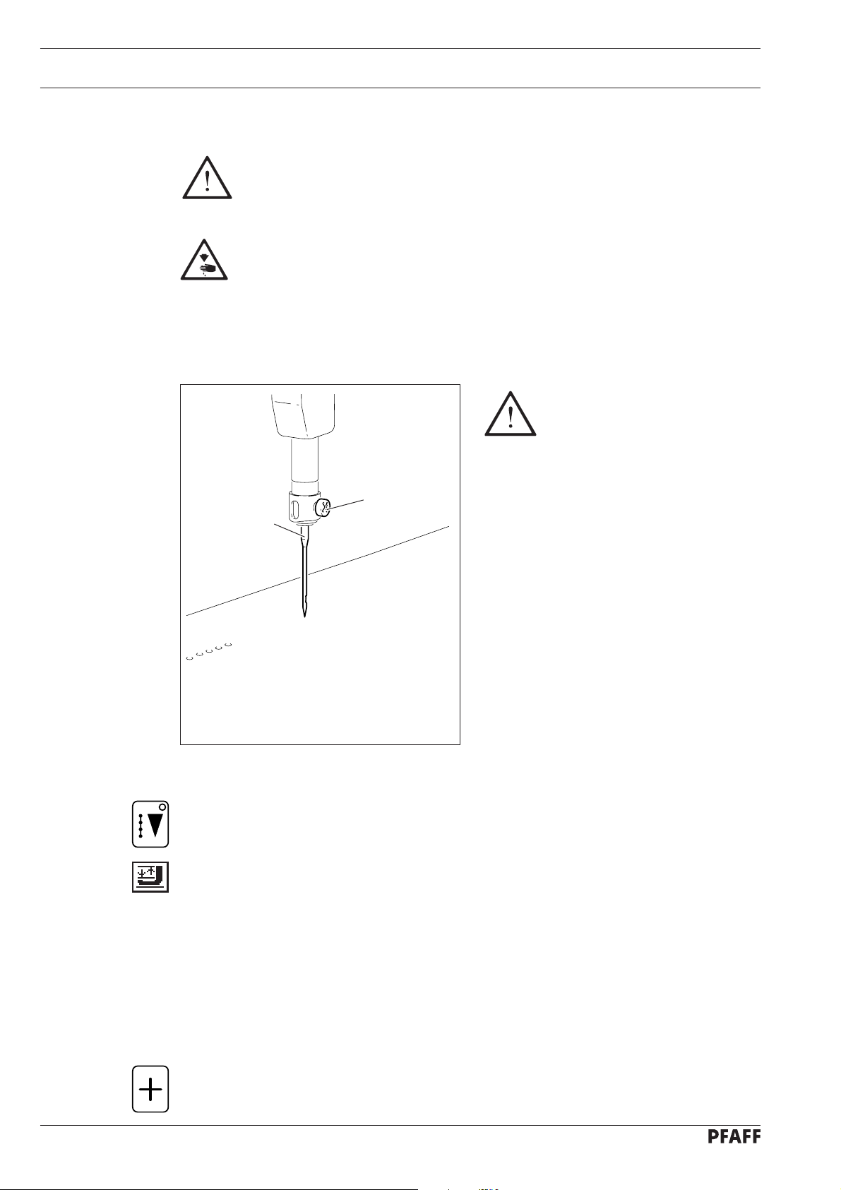
9.01 Inserting the needle
All regulations and instructions in this Instruction Manual are to be observed!
Special attention is to be paid to the safety regulations!
All preparation work is only to be carried out by appropriately trained personnel.
Before all preparation work, the machine is to be separated from the electricity
supply by removing the plug from the mains or switching off the On/Off
switch!
Only use system 134 KK
needles!
1
2
Fig. 9 - 01
● Switch on the machine, see Chapter 8.03 Switching the machine on/off.
● Select SEWING
● Select Threading aid
The pressure bar moves out of the needle area, the sewing foot is lowered and the
sewing start is locked.
mode.
function (number key 5).
75-003
9 - 1
● Loosen screw 1 and remove needle 2.
● Insert the new needle so that the long needle groove is facing forwards.
● Tighten screw 1.
● Press the Plus key.
The machine is ready for operation again.
Page 29

Preparation
75-004
9.02 Threading the needle thread /adjusting the needle thread tension
1
Fig. 9 - 02
● Switch on the machine, see Chapter 8.03 Switching the machine on/off.
● Select SEWING
mode.
+
-
● Select Threading aid function (number key 5).
The pressure bar moves out of the needle area, the sewing foot is lowered and the
sewing start is locked.
● Thread needle thread as shown in Fig. 9-02.
● Adjust the needle thread tension by turning the adjustment wheel 1.
● Press the Plus key.
The machine is ready for operation again.
9 - 2
Page 30

Preparation
9.03 Winding the bobbin thread, adjusting the thread tension
4
3
Fig. 9 - 03
-
+
6
1
2
5
● Place the empty bobbin 1 onto the bobbin winder spindle 2.
● Thread the thread in accordance with Fig. 09-03 and wind it a few times around bobbin 1
in an anti-clockwise direction.
● Switch the bobbin winder on by pushing the bobbin winder spindle 2 and lever 3
simultaneously.
The bobbin is wound during sewing.
● The tension of the thread on bobbin 1 can be adjusted using milled screw 4.
● The bobbin winder stops automatically when bobbin 1 is full.
If the thread is wound irregularly:
● Loosen nut 5.
● Turn thread guide 6 accordingly.
● Tighten nut 5.
9 - 3
Page 31

9.04 Changing the bobbin / adjusting the bobbin thread tension
1
2
Preparation
5 cm
3
4
50-009
-
+
Fig. 9 - 04
● Switch on the machine, see Chapter 8.03 Switching the machine on/off.
● Select SEWING
● Select Threading aid function (number key 5).
The pressure bar moves out of the needle area, the sewing foot is lowered and the
sewing start is locked.
● Open flap 1.
● Raise latch 2
mode.
and remove the bobbin case 3
together with the bobbin.
50-008
● Insert the filled bobbin into the bobbin case 3
the arrow when the thread is pulled out.
● Through the slot pull the thread under the spring as shown in Fig. 9-04.
● Adjust the bobbin thread tension by turning screw 4.
● Raise latch 2 and insert the bobbin case 3
● Release latch 2
● Close flap 1.
● Press the Plus key.
The machine is ready for operation again.
and press the bobbin case into the hook until you feel it lock into place.
so that the bobbin turns in the direction of
together with the bobbin in the hook.
9 - 4
Page 32

Preparation
9.05 Adjusting the height of the sewing foot
The sewing foot height is
adjusted correctly when the
sewing foot is positioned
(suspended) slightly above the
workpiece.
3
Fig. 9 - 05
9.06 Selecting a language
● Select INPUT mode by pressing the respective key.
Depending on the setting and configuration of the machine the displayed status
bar may differ from the following example.
2
● Loosen counter screw 1 and adjust the
presser foot 3
by turning milled screw 2.
● Tighten counter screw 1 again.
to the material thickness
1
75-005
100 100 50.5 5000
1 2
● Select the input menu function (number key 0).
● Select the SWITCH FUNCTIONS function with number key 3.
3
● Select the LANGUAGES function with number key 2.
2
to
1
● Select the desired language with the number keys 1 - 5:
4
● The language selected is assumed immediately once the corresponding number has been
3
4 5 6 7 9 0
1= 3= 5=
2= 4 =
entered.
D
8
F
E
Enter
Esc
Clear
bdf
9 - 5
Page 33

9.07 Selecting a seam program
Preparation
1
Enter
bis
● Switch on the machine and select INPUT
Depending on the setting and configuration of the machine, in particular the
status bar may differ from the following example.
100 100 50.5 5000
1 2
● Using the Program number selection (number key 1) or Sequence number selection
0
● Using the number keys select a previously entered seam program.
● Complete selection with Enter.
3
4 5 6 7 9 0
(number key 2) function, select the required menu.
Seam programs can be transferred from a disk to the machine memory. To do
so the READ / WRITE PROGRAM function must be selected (see Chapter
11.05 Functions in INPUT mode).
8
mode.
Enter
Esc
Clear
bdf
The CREATE/MODIFY PROGRAM function (see Chapter 11.05 Functions in
INPUT mode) is used to create a seam program on the graphics control panel.
9 - 6
Page 34

Preparation
9 - 7
Page 35

Register 06
Contents ...............................................................................Chapter - Page
10 Sewing .................................................................................................................... 10 - 1
10.01 Status bar .................................................................................................................10- 1
10.02 Automatic Program Start ......................................................................................... 10 - 2
10.03 Manual Program Start .............................................................................................. 10 - 3
10.04 Sequence program ................................................................................................... 10 - 4
10.05 Error messages ........................................................................................................ 10 - 5
10.06 Program interruption ................................................................................................ 10 - 5
11 Input ........................................................................................................................ 11 - 1
11.01 Summary of the functions in the INPUT mode ........................................................ 11 - 1
11.02 Summary of the functions in the input menu ........................................................... 11 - 2
11.03 Summary of the service functions ........................................................................... 11 - 3
11.04 Selecting functions from the menu .......................................................................... 11 - 4
11.05 Functions in the INPUT mode .................................................................................. 11 - 6
11.06 Input of seam programs ........................................................................................... 11 - 17
11.07 Examples for entering seam programs .................................................................... 11 - 24
11.07.01 Straight dart ............................................................................................................. 11 - 24
11.07.02 Curved pleat ............................................................................................................. 11 - 26
11.08 CREATE/MODIFY FREE PROGRAMS ...................................................................... 11 - 29
11.08.01 Program structure .................................................................................................... 11 -29
11.08.02 Entering the free programming function .................................................................. 11 - 29
11.08.03 Status bar in initial state (free programming)............................................................ 11 - 31
11.08.04 Summary of the functions in the initial state (free programming) ............................ 11 - 32
11.08.05 Explanation of the functions in the initial state (free programming) ......................... 11 - 33
11.08.06 Summary of the Insert functions ............................................................................. 11 - 36
11.08.07 Explanation of the insert functions ........................................................................... 11 - 37
11.08.08 An example for entering a free program .................................................................. 11 - 40
11.09 Installing operating programs ................................................................................... 11 - 46
11.09.01 Booting for software updates .................................................................................. 11 - 46
11.09.02 Booting after changing the basic control unit ........................................................... 11 - 47
Page 36

Sewing
10 Sewing
In the SEWING mode functions are available for production and production preparation. By
pressing the corresponding key on the graphics control panel, the operational mode can be
selected.
Before production begins, following work steps must be carried out:
● Prepare the machine, see Chapter 9 Preparation.
● Select SEWING
● Insert the workpiece and start the program sequence.
Information and functions of the graphics control panel are listed below and explained.
mode.
In the SEWING mode, the program sequence can be started either
automatically or manually, the differences are explained below in Chapters
10.02 Automatic Program Start and 10.03 Manual Program Start.
10.01 Status bar
In the upper section of the display screen information is shown about the current machine
status. For this purpose symbols are displayed with corresponding values.
100 100 20.5 5000
1 2
Explanation of the status bar symbols.
Program number
The number of the current program appears after the symbol for the program number.
No symbol appears for standard programs.
In the case of sequence programs
method (automatic or manual) appears after the symbol.
Seam length
The value for the seam length of the selected seam program appears after this symbol.
3
1
AUT
4 5 6 7 9 0
8
the corresponding sequence number and the move-on
Enter
Esc
Clear
bdf
10 - 1
Depth
The value for the programmed depth of the selected seam program appears after this
symbol.
Piece counter
The actual number of pieces is shown after this symbol.
Page 37

10.02 Automatic Program Start
In the case of an automatic program start, the program sequence begins as soon as the
loading table with the workpiece is moved forward.
Starting position of the machine
Sewing
to
100 100 20.5 0
BOBBIN 0 / 10000
1 2
Explanation of the symbols in the pictogram bar:
Automatic program start
The pictogram indicates that the program starts automatically.
If the Manual program start
function, see Chapter 10.03 Manual program start
Starting position
This is a direct function to bring the machine into its starting position.
Sewing foot up/down, threading aid
This is a direct function for raising or lowering the sewing foot. At the same time the
pressure bar is switched on or off and if necessary moved into the threading position.
Depth correction dependent on the material
The depth specified in the seam program is corrected according to the function selected.
The maximum value for the depth correction can be set in the input mode under the Sewing
head functions
the selected depth correction appears on a dark background.
3
4 5 6 7 9 0
(number key 4)
function, see Chapter 11.05 Functions in the INPUT mode. The symbol for
8
(number key 1)
function is selected, the machine switches over to this
(number key 5)
Enter
..
.
..
(number keys 6 – 0)
Esc
Clear
bdf
The depth correction value is reduced by 100%
The depth correction value is reduced by 50%
The specified depth remains unchanged.
The depth correction value is increased by 50% of the specified depth.
The depth correction value is increased by 100% of the specified depth.
of the specified depth.
of the specified depth.
10 - 2
Page 38

Sewing
10.03 Manual Program Start
In the case of a manual program start, the program sequence is started by selecting the
Start Start
Start function on the graphics control panel after the loading table has been moved forward.
Start Start
Starting position of the machine
to
100 100 20.5 0
BOBBIN 0 / 10000
1 2
3
4 5 6 7 9 0
8
Enter
Esc
Clear
bdf
Explanation of the symbols in the pictogram bar:
Manual program start
(number key 1)
The pictogram indicates that the program has been started manually.
If the Automatic program start
function is selected, the machine switches over to this
function, see Chapter 10.02 Automatic program start.
Starting position
(number key 4)
This is a direct function to bring the machine into its starting position.
Sewing foot up/down, threading aid
(number key 5)
This is a direct function for raising or lowering the sewing foot. At the same time the
pressure bar is switched on or off and if necessary moved into the threading position.
Depth correction dependent on the material
(number keys 6 – 0)
See Chapter 10.02 Automatic program start.
Loading table moved forward
100 100 20.5 5000
BOBBIN 2500 / 10000
1 2
3
4 5 6 7 9 0
8
Enter
Esc
Clear
bdf
Explanation of the symbols changed in the pictogram bar:
Start
(number key 1)
Direct function to start the program sequence.
Step-by-step forwards
(number key 2)
With this function the seam pattern can be traced forwards step by step.
10 - 3
Page 39

Machine running
Sewing
100 100 20.5 5000
BOBBIN 2500 / 10000
1 2
3
4 5 6 7 9 0
8
Enter
Explanation of the symbols in the pictogram bar:
Stop (number key 1)
Direct function to stop the entire program sequence
(see Chapter 10.06 Program interruption
Depth correction dependent on the material
))
)
))
(number keys 6 – 0)
See Chapter 10.02 Automatic program start.
Intermediate machine stop
100 100 20.5 0
BOBBIN 0 / 10000
1 2
3
4 5 6 7 9 0
8
Enter
Esc
Clear
bdf
Esc
Clear
bdf
Explanation of the symbols in the pictogram bar:
Start
(number key 1)
Direct function to continue the program sequence.
Step-by-step forwards
With this function the seam pattern can be traced forwards step by step.
Starting position
(number key 4)
This is a direct function to bring the machine into its starting position.
Increase insertion depth
The insertion depth for this seam can be increased or reduced.
10.04 Sequence program
In sequence programs separate programs can be combined and saved under one program
number. The selection of a sequence program and the move-on method can be recognised
by the corresponding symbol in the status bar.
100 100 20.5 0
100 | 190 | 105
1
AUT
(number key 2)
(number key 9) / Reduce insertion depth
Esc
BOBBIN 0 / 10000
Clear
(number key 0)
1 2
3
4 5 6 7 9 0
8
Enter
The sequence consists of the programs 100, 190 and 105.
bdf
10 - 4
Page 40

Sewing
1
AUT
Automatic switching to next sequence
The separate programs of the sequence are processed automatically after each other. The
program number displayed on a dark background shows which part must be inserted next.
1
MAN
Manual switching to next sequence
The current program of a sequence is processed until another program is selected from the
sequence.
Within the sequence the program is selected with the arrow keys.
The program number displayed on a dark background shows which program has been
currently selected.
10.05 Error messages
If an error message occurs, text and pictogram bars in the display are written over. An error
message can be caused by incorrect settings, defective elements or seam programs, as well
as by overload conditions.
● Before machine operation can continue, the error must be corrected.
How to correct the error:
Enter
● Press Enter to move back to an incorrect input.
● Correct the input.
10.06 Program interruption
A program sequence can be interrupted by activating the Stop function on the graphics
control panel.
100 100 20.5 0
100 | 190 | 105
1 2
Explanation of the symbols in the pictogram bar:
Start
(number key 1)
Direct function to continue the program sequence.
Step-by-step forwards
With this function the seam pattern can be traced forwards or backwards step by step.
Combined with the Start
Start
function is pressed in addition to the activated Step-by-step
Starting position
This is a direct function to bring the machine into its starting position.
1
AUT
3
4 5 6 7 9 0
(number key 2) / Step-by-step backwards
function, the seam pattern sequence runs automatically when the
(number key 4)
BOBBIN 0 / 10000
8
Enter
Esc
Clear
bdf
(number key 3)
……
…function.
……
10 - 5
Sewing foot up / down, threading aid
(number key 5)
This is a direct function for raising or lowering the sewing foot. At the same time the
pressure bar is switched on or off and if necessary moved into the threading position.
Depth correction dependent on the material
(number keys 6 – 0)
See Chapter 10.02 Automatic program start.
Page 41

11 Input
This chapter lists and describes the functions in the INPUT mode. This operational mode
includes the functions for program management, language selection, machine setting and
configuration, as well as for service and adjustment work. However this chapter does not
describe how to create a seam program. For information on how to create seam programs
please refer to the relevant instruction manual.
11.01 Summary of the functions in the INPUT mode
INPUT
mode
Program number selection
Sequence program number selection
Modify selected program
Create program
Input
1 - DART 1
2 - DART 2
3 - PLEAT 1
4 - PLEAT 2
5 - BASTING STITCH
Create / modify free program
Enter seam parameters
1 - STARTTACK
2 - STITCH CONDENSING SEAM START
3 - ENDTACK
4 - STITCH CONDENSING SEAM END
5 - ANGLE SEAM END
6 - BASTING STITCH
Bobbin thread functions
1 - RESET STITCH COUNTER
2 - BOBBIN THREAD PRESELECT
Sewing head functions
1 - MAXIMUM SPEED
2 - SPEED TACK / REDUCTION
3 - SPEED BASTING STITCH
4 - INTERMITTENT STOP
5 - MAX. DEPTH CORRECTION
Input menu (see Chapter 11.02 Summary of the functions in the input menu)
1 - PROGRAM MANAGEMENT
2 - COUNTER
3 - SWITCH FUNCTIONS
4 - TIMES
5 - SERVICE (SEE CHAPTER 11.03 SUMMARY OF THE SERVICE FUNCTIONS)
11 - 1
Page 42

Input
11.02 Summary of the functions in the input menu
INPUT
mode
Input menu
1 - PROGRAM MANAGEMENT 1 - DIRECTORY 1 - DIRECTORY OF MEMORY
2 - READ/WRITE PROGRAM 1 - READ ONE PROGRAM FROM DISK
3 - DELETE PROGRAM 1 - DELETE ONE PROGRAM IN MEMORY
4 - FORMAT DISK
2 - DIRECTORY OF DISK
2 - READ ALL PROGRAMS FROM DISK
3 - WRITE ONE PROGRAM ON DISK
4 - WRITE ALL PROGRAMS ON DISK
2 - DELETE ALL PROGRAMS IN MEMORY
3 - DELETE ONE PROGRAM ON DISK
4 - DELETE ALL PROGRAMS ON DISK
2 - COUNTERS 1 - RESET PIECE COUNTER
2 - THREAD MONITOR 1 - SUPPRESSED STITCHES NEEDLE
THREAD MONITOR
2 - REACTION TIME THREAD MONITOR
3 - NUMBER OF SLOW START - STITCHES
4 - CARRIAGE START (NIS)
5 - START FOR THREAD TRIMMING
3 - SWITCH FUNCTIONS 1 - THREAD MONITOR 1 - NEEDLE THREAD MONITOR
2 - BOBBIN THREAD MONITOR
2 - LANGUAGE SELECTION 1 - GERMAN
2 - ENGLISH
3 - FRENCH
4 - SPANISH
5 - TURKISH
3 - LOCK/RELEASE FUNCTIONS
4 - OTHER FUNCTIONS 1 - MOVE TAKE - OVER
2 - THREADING POSITION
4 - TIMES 11 - AIR BLAST TIME
5 - SERVICE (SEE CHAPTER 11.03 SUMMARY OF SERVICE FUNCTIONS)
11 - 2
Page 43

11.03 Summary of the service functions
INPUT
mode
Input menu
5 - SERVICE
1 - SEWING DRIVE FUNCTIONS 1 - TURN SEWING MOTOR
2 - STEPPING MOTOR FUNCTIONS 1 - STEPPING MOTOR 1, SMX
3 - INPUTS / OUTPUTS
Input
2 - THREAD TRIMMING PROCEDURE
3 - CUTTING SPEED - PRESELECT
2 - STEPPING MOTOR 2, SMY
3 - STEPPING MOTOR 3, SMD
4 - ADJUST ZERO POINTS 1 - CARRIAGE POSITION
2 - DEPTH
3 - NEEDLE POSITION
4 - CORRECTION VALUE START POINT
5 - ADJUSTMENTS READ/WRITE 1 - READ MACHINE DATA FROM DISK
2 - WRITE MACHINE DATA TO DISK
3 - READ ZERO POINTS FROM DISK
4 - WRITE ZERO POINTS TO DISK
6 - OTHER FUNCTIONS 1 - CARRY OUT COLD START
2 - DISPLAY SOFTWARE STATUS
3 - CONTRAST SETTING OF DISPLAY
4 - CHANGE CODE NUMBER
5 - INSTALL OPERATING SYSTEM
The service functions are explained in Chapter 11.05 Functions in the INPUT
mode.
11 - 3
Page 44

Input
11.04 Selecting functions from the menu
An example is designed to show how to move about within menu levels.
Contrast setting of display:
● By pressing the corresponding key, select INPUT
mode
(LED in key lights up)
100 100 50.5 5000
1 2
● Select input menu
1 - PROGRAM MANAGEMENT .....
2 - COUNTER .....
3 - SWITCH FUNCTIONS .....
4 - TIMES .....
5 - SERVICE .....
1 2
● By pressing number key 5, call up the SERVICE function.
5
1 - SEWING DRIVE FUNCTIONS .....
2 - STEPPING MOTOR FUNCTIONS .....
3 - DISPLAY INPUTS / OUTPUTS
4 - ADJUST ZERO POINT .....
5 - ADJUSTMENTS READ/WRITE .....
6 - OTHER FUNCTIONS .....
3
4 5 6 7 9 0
function (press number key 0)
3
4 5 6 7 9 0
8
8
Enter
Enter
Esc
Clear
bdf
Esc
Clear
bdf
Esc
Clear
1 2
● With number key 6 select OTHER FUNCTIONS.
6
1 - CARRY OUT COLD START
2 - DISPLAY SOFTWARE STATUS
3 - CONTRAST SETTING OF DISPLAY
4 - CHANGE CODE NUMBER
5 - INSTALL OPERATING SYSTEM
1 2
3
5
8
● Insert the code number (standard setting: 3586) using the number keys.
6
CODE NUMBER?
3586
[ PERMISSIBLE 0000 - 9999 ]
1 2
3
4 5 6 7 9 0
3
4 5 6 7 9 0
3
4 5 6 7 9 0
8
8
8
Enter
Enter
Enter
bdf
Esc
Clear
bdf
Esc
Clear
bdf
11 - 4
Page 45

Input
Enter
Enter
● Confirm code input with Enter.
● Select the CONTRAST SETTING OF DISPLAY function (number key 3)
3
CONTRAST SETTING
ADJUST WITH +, - KEYS
1 2
3
4 5 6 7 9 0
8
Enter
Esc
Clear
The contrast setting is changed immediately when the key is pressed and does
not have to be confirmed with Enter. On no account may the contrast be
reduced to such an extent that it is no longer possible to read the display!
● The contrast can be changed as required using the plus/minus keys.
● Press Enter
to exit the function.
bdf
Summary of the function selections
INPUT
mode
0
Input menu
function
(number key 0)
1 - PROGRAM MANAGEMENT
2 - COUNTER
3 - SWITCH FUNCTIONS
4 - TIMES
5
5 - SERVICE
1 - SEWING DRIVE FUNCTIONS
2 - STEPPING MOTOR FUNCTIONS
3 - DISPLAY INPUTS / OUTPUTS
4 - ADJUST ZERO POINT
5 - ADJUSTMENTS READ/WRITE
6
6 - OTHER FUNCTIONS
1 - CARRY OUT COLD START
2 - DISPLAY SOFTWARE STATUS
3
3 - CONTRAST SETTING OF DISPLAY
4 - CHANGE CODE NUMBER
5 - INSTALL OPERATING SYSTEM
11 - 5
Page 46

Input
11.05 Functions in the INPUT mode
Initial state in the INPUT
100 100 50.5 5000
1 2
1
AUT
3
4 5 6 7 9 0
mode
Esc
Clear
8
Enter
bdf
Explanation of the functions:
Program number selection
(number key 1)
This function is for the selection of the desired program number.
Sequence program number selection
(number key 2)
With this function it is possible to select the sequence program number, the method of
moving the sequence forward and the sequence. When a sequence program number is
selected, the sequence saved under this number is displayed.
Create / modify current program
(number key 4)
With this function it is possible to create or modify the currently selected program using the
graphics control panel.
Create / modify program
(number key 5)
Using the graphics control panel with this function seam programs can be created or
modified, the seam pattern and the corresponding program number are selected after the
function has been called up, see Chapter 11.06 Entering seam programs
Create / modify free program
(number key 6)
..
.
..
With this function free seam programs can be created or modified on the machine, see
Chapter 11.07 Create / modify free program
..
.
..
Seam parameters (number key 7)
This function opens a menu for entering seam parameters:
1 - STARTTACK
2 - STITCH CONDENSING SEAM START
3 - ENDTACK
4 - STITCH CONDENSING SEAM END
4 - ANGLE SEAM END
5 - BASTING STITCH
1 2
1
3
4 5 6 7 9 0
STARTTACK
8
Enter
Esc
Clear
bdf
With this function the number of stitches for the start backtack can be entered.
11 - 6
STITCH CONDENSING SEAM START
2
With this function the stitch length and number of condensed stitches at the seam
start can be entered.
ENDTACK
3
With this function the number of stitches for the end backtack can be entered.
Page 47

STITCH CONDENSING SEAM END
4
With this function the stitch length and number of condensed stitches at the send of
the seam can be entered.
ANGLE SEAM END
5
With this function the number of stitches and angle at the seam end can be entered.
BASTING STITCH
With this function the stitch length and number of stitches at the beginning and end of
6
the seam can be entered.
Input
Bobbin thread functions
(number key 8)
This function opens a menu for the selection of various bobbin thread functions:
1 - RESET STITCH COUNTER
2 - BOBBIN - THREAD PRESELECT 10000 STITCHES
1 2
1
3
4 5 6 7 9 0
RESET STITCH COUNTER
8
Enter
Esc
Clear
bdf
This function resets the stitch counter to "0", e.g. after an unplanned bobbin change.
BOBBIN THREAD PRESELECT
This function is used to enter the number of stitches, after which the machine stops
2
automatically for a bobbin change.
Sewing head functions
(number key 9)
The function opens a menu for the selection of various sewing head functions:
1 - MAXIMUM SPEED 4500 RPM
2 - SPEED TACK / REDUCTION 4500 RPM
3 - SPEED BASTING STITCH 1000 RPM
4 - INTERMITTENT STOP ON
5 - MAX: DEPTH CORRECTION 0.5 MM
1 2
1
3
4 5 6 7 9 0
MAXIMUM SPEED
8
Enter
Esc
Clear
bdf
This function is for entering the maximum speed
SPEED TACK / REDUCTION
2
This function is for entering the reduced speed for backtacking stitches at the beginning
and end of the seam.
SPEED BASTING STITCH
3
This function is for entering the speed of the basting stitch.
INTERMITTENT STOP
4
With this function the sequence interruption after loading the workpiece (for manual
depth correction) can be switched on or off.
11 - 7
Page 48

Input
MAX: DEPTH CORRECTION
5
With this function the value for the maximum depth correction can be entered. The indi-
vidual intermediate values are calculated automatically.
Input menu
(number key 0)
This function opens a menu for selecting various functions from other menu levels
1 - PROGRAM MANAGEMENT .....
2 - COUNTER .....
3 - SWITCH FUNCTIONS .....
4 - TIMES .....
5 - SERVICE .....
1 2
1
3
4 5 6 7 9 0
8
PROGRAM MANAGEMENT
Enter
Esc
Clear
bdf
This function opens a menu for organizing seam programs:
1 - DIRECTORY .....
2 - READ/WRITE PROGRAM .....
3 - DELETE PROGRAM .....
4 - FORMAT DISK
1 2
1
3
4 5 6 7 9 0
DIRECTORY
8
Enter
Esc
Clear
bdf
This function opens a menu with functions for listing the directories of the memory:
1 - DIRECTORY OF MEMORY
2 - DIRECTORY OF DISK
1 2
1
3
4 5 6 7 9 0
DIRECTORY OF MEMORY
8
Enter
This function displays the contents of the machine memory.
DIRECTORY OF DISK
2
Displays the contents of a disk. Program numbers valid for this machine are
displayed.
READ/WRITE PROGRAM
2
This functions opens a menu for transferring seam programs:
1 - READ ONE PROGRAM FROM DISK
2 - READ ALL PROGRAMS FROM DISK
3 - WRITE ONE PROGRAM ON DISK
4 - WRITE ALL PROGRAMS ON DISK
Esc
Clear
bdf
Esc
Clear
11 - 8
1 2
3
4 5 6 7 9 0
8
Enter
bdf
Page 49

3
READ ONE PROGRAM FROM DISK
1
A selected program is read from a disk into the machine memory.
READ ALL PROGRAMS FROM DISK
2
All the programs on a disk are read into the machine memory.
WRITE ONE PROGRAM ON DISK
3
A selected program is written from the machine memory onto a disk.
WRITE ALL PROGRAMS ON DISK
4
All programs from the machine memory are written onto a disk.
DELETE PROGRAMS
The function opens a menu for deleting seam programs:
Input
1 - DELETE ONE PROGRAM IN MEMORY
2 - DELETE ALL PROGRAMS IN MEMORY
3 - DELETE ONE PROGRAM ON DISK
4 - DELETE ALL PROGRAMS ON DISK
1 2
1
3
4 5 6 7 9 0
DELETE ONE PROGRAM IN MEMORY
A selected program is deleted in the machine memory.
DELETE ALL PROGRAMS IN MEMORY
2
All the programs in the machine memory are deleted.
DELETE ONE PROGRAM ON DISK
3
A selected program is deleted on a disk.
DELETE ALL PROGRAMS ON DISK
4
All the programs on a disk are deleted.
FORMAT DISK
4
Formats a disk and names it "K3586".
Esc
Clear
8
Enter
bdf
When you format a disk, all files on the disk are deleted!
11 - 9
Page 50

Input
COUNTER
2
This function opens a menu for customizing the counters:
1 - RESET PIECE COUNTER
2 - THREAD MONITOR .....
3 - NUMBER OF SLOW START - STITCHES 2 STITCHES
4 - CARRIAGE START (NIS) 90°
5 - START FOR THREAD TRIMMING 200°
1 2
1
3
4 5 6 7 9 0
RESET PIECE COUNTER
8
Enter
Esc
Clear
bdf
With this function the piece counter is set at "0" for the daily production.
THREAD MONITOR
2
The function opens a menu for changing the thread monitor counters:
1 - SUPPRESSED STITCHES NEEDLE THREAD MONITOR: 5STITCHES
2 - REACTION TIME NEEDLE THREAD MONITOR: 2
1 2
1
3
4 5 6 7 9 0
8
SUPPRESSED STITCHES NEEDLE THREAD MONITOR
Enter
Esc
Clear
Changes the number of stitches, for which the needle thread monitor is not
active during sewing.
bdf
REACTION TIME, NEEDLE THREAD MONITOR
2
With this function the sensitivity of the needle thread monitor is changed
(1 = quick reaction, max. sensitivity).
NUMBER OF SLOW START - STITCHES
3
Changes the number of stitches, which are to be sewn at reduced speed when
sewing on a section of the workpiece.
CARRIAGE START (NIS)
4
This function changes the time for starting the motors of the carriage drive.
(° = degrees after t.d.c. needle bar).
START FOR THREAD TRIMMING
5
Changes the time at which the impulse to start thread trimming is sent to the
thread trimming valve (º = degrees after t.d.c. needle bar).
11 - 10
Page 51

3
SWITCH FUNCTIONS
3
This function opens a menu for switching machine functions on or off.
Input
1 - THREAD MONITOR .....
2 - LANGUAGE SELECTION .....
3 - LOCK/RELEASE FUNCTIONS
4 - OTHER FUNCTIONS .....
1 2
1
3
4 5 6 7 9 0
THREAD MONITOR
8
Enter
This function opens a menu for selecting thread monitors:
1 - NEEDLE THREAD MONITOR ON
2 - BOBBIN THREAD MONITOR ON
1 2
1
3
4 5 6 7 9 0
8
NEEDLE THREAD MONITOR
With this function the needle thread monitor is switched on or off.
BOBBIN THREAD MONITOR
2
This function counts the stitches.
Esc
Clear
Enter
bdf
Esc
Clear
bdf
LANGUAGE SELECTION
2
This function opens a menu for the selection of the languages displayed (see
Chapter 9.06 Language selection):
1 - GERMAN
2 - ENGLISH
3 - FRENCH
4 - SPANISH
1 2
3
4 5 6 7 9 0
8
Enter
Esc
Clear
bdf
LOCK/RELEASE FUNCTIONS
With this function all functions in the INPUT mode can be released, secured with
a code number and made accessible to authorized personnel only by means of a
key.
A table with the code numbers of the individual functions can be found in Chapter
14.03.01 Tables for lock/release functions.
11 - 11
Page 52

Input
OTHER FUNCTIONS
4
This function opens a menu for switching the other functions on or off.
1 - MOVE TAKE OVER
2 - THREADING POSITION
1 2
1
3
4 5 6 7 9 0
MOVE TAKE OVER
8
When this function is switched on, the material take over is moved
automatically by a certain amount during the sewing cycle.
THREADING POSITION
2
When the threading aid function is switched on, the pressure bar is moved.
TIMES
4
This function opens a menu for altering the time settings.
AIR BLAST TIME
1
This function is used to set the duration of the air blast for blasting out the material
at the end of the seam.
Enter
Esc
Clear
bdf
11 - 12
Page 53

SERVICE
5
This functions opens a menu for selecting the service functions:
Input
1 - SEWING DRIVE FUNCTIONS .....
2 - STEPPING MOTOR FUNCTIONS .....
3 - DISPLAY INPUTS/OUTPUTS
4 - ADJUST ZERO POINT .....
5 - ADJUSTMENTS READ/WRITE .....
6 - OTHER FUNCTIONS .....
1 2
1
3
4 5 6 7 9 0
SEWING DRIVE FUNCTIONS
8
Enter
This function opens a menu for checking the sewing motor:
1 - TURN SEWING MOTOR
2 - THREAD TRIMMING PROCEDURE
3 - CUTTING SPEED - PRESELECT 200 RPM
1 2
3
4 5 6 7 9 0
8
Before activating the following functions, make sure that the
needle can enter the needle hole without any problem!
TURN SEWING MOTOR
1
With his function the sewing motor can be started and stopped again. The
speed can be pre - selected or even altered during running, using the plus/
minus keys.
Esc
Clear
Enter
bdf
Esc
Clear
bdf
THREAD TRIMMING PROCEDURE
2
This function starts the thread trimming procedure.
CUTTING SPEED - PRESELECT
3
This function preselects the positioning speed for thread cutting.
STEPPING MOTOR FUNCTIONS
2
This function opens a menu for moving the stepping motors:
1 - STEPPING MOTOR 1 (X)
2 - STEPPING MOTOR 2 (Y)
3 - STEPPING MOTOR 3 (D)
1 2
3
4 5 6 7 9 0
8
Before activating the following functions, make sure that the carriage
drive can move freely!
STEPPING MOTOR 1 (X)
1
This function moves stepping motor 1 (X - axis).
Enter
Esc
Clear
bdf
11 - 13
Page 54

Input
STEPPING MOTOR 2 (Y)
2
This function moves stepping motor 2 (Y - axis).
STEPPING MOTOR 3 (D)
3
This function moves stepping motor 2 (depth).
DISPLAY INPUTS/OUTPUTS
3
After this function has been selected, the states of inputs and outputs are
displayed: 1 = Input actuated / output switched
0 = Input not actuated / output not switched
NODE 1 (A??) : 1 - - - - - - 8 9 - - - - - - 16
INPUTS : 00101101 10101000
OUTPUTS : 00000100 00100000
1 2
3
4 5 6 7 9 0
8
With this function (number key 0) a menu is opened, in which outputs
can be set or reset. The required output is selected with a code number.
A signal is given for any errors occurring. In the case of outputs equipped
with a transmitter for sending a response signal, the response time is
measured and displayed.
There is a table of the inputs and outputs with code numbers in Chapter
14.03 Tables.
ADJUST ZERO POINT
4
This function opens a menu for adjusting the zero points
1 - CARRIAGE POSITION
2 - DEPTH
3 - NEEDLE POSITION
4 - CORRECTION VALUE START POINT 1.0 mm
Enter
Esc
Clear
bdf
Esc
Clear
11 - 14
1 2
1
3
4 5 6 7 9 0
CARRIAGE POSITION
8
Enter
bdf
With this function the basic position of the carriage can be set.
DEPTH
2
With this function the distance between material take over and pressure bar
can be set.
NEEDLE POSITION
3
This function sets the position "TDC needle bar".
CORRECTION VALUE START POINT
4
With this function it is possible to correct the seam starting point in X -
direction.
Page 55

6
ADJUSTMENTS READ/WRITE
5
After this function has been called up, a menu is opened for entering or copying
machine data:
Input
1 - READ MACHINE DATA FROM DISK
2 - WRITE MACHINE DATA TO DISK
3 - READ CONF./ZERO POINTS FROM DISK
4 - WRITE CONF./ZERO POINTS TO DISK
1 2
1
3
4 5 6 7 9 0
8
READ MACHINE DATA FROM DISK
Enter
Esc
Clear
bdf
With this function it is possible to read machine data (file name: MDAT)
which is saved on a disk, into the machine memory (e.g. after a cold start).
WRITE MACHINE DATA TO DISK
2
With this function the data for the machine setting (file name: MDAT) can be
written on to a disk.
There is a table of transferable machine data in the service manual for this
machine.
READ CONFIGURATION/ZERO POINTS FROM DISK
3
With this function it is possible to read the machine configuration and the
zero points (file name: KONF), which are saved on a disk, into the machine
memory (e.g. after a master reset).
WRITE CONFIGURATION/ZERO POINTS TO DISK
4
With this function it is possible to write the machine configuration and the
zero points (file name: KONF) on to a disk.
OTHER FUNCTIONS
This function opens a menu with various other functions:
1 - CARRY OUT COLD START
2 - DISPLAY SOFTWARE STATUS
3 - CONTRAST SETTING OF DISPLAY
4 - CHANGE CODE NUMBER
5 - INSTALL OPERATING SYSTEM
1 2
1
3
4 5 6 7 9 0
CARRY OUT COLD START
8
Enter
Esc
Clear
bdf
With this function a cold start can be carried out.
During this procedure all settings, except the zero point settings and the
machine configuration, are returned to the initial load status; all programs in
the machine memory are deleted.
DISPLAY SOFTWARE STATUS
2
After this function has been selected, the part numbers of the machine
software and the software versions of various controllers are displayed.
11 - 15
Page 56

Input
CONTRAST SETTING OF DISPLAY
3
Under no circumstances may the display be adjusted to such an
extent, that it is no longer possible to read the display.
With this function the contrast setting of the display can be altered.
CHANGE CODE NUMBER
4
After a cold start, this number is 3586. This function allows you to select your
own code number from 0000 - 9999.
Functions secured by a code number can only be selected with
the respective code.
INSTALL OPERATING SYSTEM
5
With this function, after the boot disk K3586BOOT1 has been inserted, the
operating software is loaded for a software update, see Chapter 11.09
Installing operating programs.
11 - 16
Page 57

11.06 Input of seam programs
Seam programs can be created or modified with the graphics control panel, using the
Create/Modify program
corresponding program number can be selected.
The selection of the seam type depends on the additional seam requirements:
Starttack pre - set pre - set pre - set pre - set
Stitch condensing optional optional optional optional
seam start
End tack not possible not possible pre - set not possible
Stitch condensing automatic automatic optional automatic
seam end
function. After the function has been selected, the seam type and
DART 1 DART 2 PLEAT 1 PLEAT 2
Input
Angle seam end automatic automatic not possible not possible
Basting stitch not possible not possible optional optional
Basic status of the seam program input
1 - DART 1
2 - DART 2
3 - PLEAT 1
4 - PLEAT 2
5 - BASTING STITCH
1 2
3
4 5 6 7 9 0
8
Enter
Esc
Clear
bdf
● After the required seam type has been selected (number keys 1 to 5), the program
number must be entered.
Use the arrow keys
to enter the program number or stitch length in the basic
pattern of each seam type.
11 - 17
Page 58

Input
DART 1
1
With this function the corresponding seam type can be programmed.
Program numbers 100 - 199 are allocated to the seam type "Dart 1"
➞
➞
:
2
1
+
3
-
4
1: 10.0 2: 100 3: +0
100 2.2
4: 0
Esc
Clear
1 2
1
3
Number key 1
4 5 6 7 9 0
8
Enter
bdf
Press this number key to enter the value for dart depth.
Number key 2
2
Press this number key to enter the value for dart length.
Number key 3
3
Press this number key to enter the value for curve.
Number key 4
4
Press this key to enter the value for shifting the starting point.
Starttack / stitch condensing seam start
(number key 8)
With this function it is possible to define the type of seam starttack. By pressing a
key it is possible to select either a tack or stitch condensation at the beginning of
the seam.
11 - 18
Page 59

2
3
6
5
DART 2
2
With this function the corresponding seam type can be programmed.
Program numbers 200 - 299 are allocated to the seam type "Dart 2"
➞
➞
:
2
+
1
3
6
+
-
5
7
-
4
1: 10.0 2: 100 5: +0
3:10.0 4:50 6:+0
200 2.2
7: 0
Input
Esc
Clear
1 2
1
3
Number key 1
4 5 6 7 9 0
8
Enter
bdf
Press this number key to enter the value for dart depth.
Number key 2
Press this number key to enter the value for dart length.
Number key 3
Press this number key to enter the value for depth at waist.
Number key 4
4
Press this number key to enter the value for length at waist.
Number key 5 / number key 6
Press these number keys to enter the values for curve.
Number key 7
7
Press this key to enter the value for shifting the starting point.
Starttack / stitch condensing seam start
(number key 8)
With this function it is possible to define the type of seam starttack. By pressing a
key it is possible to select either a tack or stitch condensation at the beginning of
the seam.
11 - 19
Page 60

Input
PLEAT 1
3
With this function the corresponding seam type can be programmed.
Program numbers 300 - 399 are allocated to the seam type "Pleat 1".
➞
➞
:
2
1
3
+
4
-
5
1: 10.0 2: 40 4: +0
3: 20.0 5: 0
300 2.2
Clear
Esc
1 2
1
3
Number key 1
4 5 6 7 9 0
8
Enter
bdf
Press this number key to enter the value for pleat depth.
Number key 2
2
Press this number key to enter the value for pleat length.
Number key 3
3
Press this number key to enter the value for depth at hip.
Number key 4
4
Press this number key to enter the value for curve.
Number key 5
5
Press this key to enter the value for shifting the starting point.
Starttack / stitch condensing seam start
(number key 8)
With this function it is possible to define the type of seam starttack. By pressing a
key it is possible to select either a tack or stitch condensation at the beginning of
the seam.
End tack / Stitch condensing seam end
(number key 9)
With this function it is possible to define the type of seam end tack. By pressing a
key it is possible to select either a tack or stitch condensation at the end of the
seam.
Basting stitch
(number key 0)
With this function it is possible to attach a basting stitch.
(The symbol for the currently selected type of basting stitch is always displayed).
➞
➞
:
300 2.2
8
Enter
Esc
Clear
bdf
1 2
2
1
3
4 5 6 7 9 0
1: 50 2: 140
11 - 20
Page 61

Input
The depth of the basting stitch corresponds to the depth of the pleat at the hip.
The beginning, end and type of basting stitch can be defined with the following
functions.
Number key 1
1
After pressing this key, the value for the basting stitch start can be entered.
Number key 2
2
After pressing this key, the value for the basting stitch end can be entered.
Basting stitch type
(number key 0)
After pressing this key it is possible to select two different types of basting
stitches. The symbol for the currently selected basting stitch type is
displayed.
PLEAT 2
4
With this function the corresponding seam type can be programmed.
Program numbers 400 - 499 are allocated to the seam type "Pleat 2".
➞
➞
:
2
1
1 2
1
3
+
6
9
-
4
3
Number key 1
5
+
7
-
1: 20.0 2: 50 6: +0
3: 20.0 4: 40 7: +0
5: 10.0 9: 0
4 5 6 7 9 0
400 2.2
8
Clear
Enter
Press this number key to enter the value for pleat depth.
Esc
bdf
Number key 2
2
Press this number key to enter the value for pleat length.
Number key 3
3
Press this number key to enter the value for depth at hip.
Number key 4
4
Press this number key to enter the value for length at hip.
Number key 5
5
Press this key to enter the value for end of pleat depth.
11 - 21
Page 62

Input
6
Number key 6 / number key 7
7
Press this number key to enter the value for curve.
Number key 9
9
Press this key to enter the value for shifting the starting point.
Starttack / stitch condensing seam start
(number key 8)
With this function it is possible to define the type of seam starttack. By pressing a
key it is possible to select either a tack or stitch condensation at the beginning of
the seam.
Basting stitch
(number key 0)
With this function it is possible to attach a basting stitch.
(The symbol for the currently selected type of basting stitch is always displayed).
➞
➞
:
400 2.2
8
Enter
Esc
Clear
bdf
1 2
2
1
3
4 5 6 7 9 0
1: 50 2: 140
The depth of the basting stitch corresponds to the depth of the pleat at the hip.
The beginning, end and type of basting stitch can be entered as described above
under the function "PLEAT 1".
11 - 22
Page 63

BASTING STITCH
3
5
With this function the corresponding seam type can be programmed.
Program numbers 500 - 599 are allocated to the seam type "Basting stitch"
➞
➞
:
2
1
3
1: 10.0 2: 100
500
3: 0
Esc
Clear
Input
1 2
1
3
Number key 1
4 5 6 7 9 0
8
Enter
bdf
Press this number key to enter the value for basting stitch depth.
Number key 2
2
Press this number key to enter the value for basting stitch length.
Number key 3
Press this key to enter the value for shifting the starting point.
Basting stitch type
(number key 0)
By pressing the number key several times, it is possible to select 2 different types
of basting stitch. The symbol for the currently selected basting stitch type is
displayed.
11 - 23
Page 64

Input
11.07 Examples for entering seam programs
11.07.01 Straight dart
Dart length = 105 mm
20 mm
Waist depth =
Dart depth = 20 mm
Waist length = 57 mm
- To create a seam pattern, seam type "Dart 2" must be used.
- From the program group stipulated for this seam type (200 - 299),
program number 222 should be selected for the seam program.
- The stitch length must be 2.0 mm.
--
- Backtacking stitches
--
should be carried out at the beginning of the seam.
2
Enter
● Switch on the machine and select INPUT mode.
● Select the Create program
● Select the DART 2 function.
2
2
2
● Enter the program number.
● Press Enter
1
+
5
7
-
4
1 2
..
.
..
➞
2
+
3
6
-
3
4 5 6 7 9 0
➞
1: 10.0 2: 100 5: +0
3:10.0 4:50 6:+0
● Using the left arrow key
function (number key 5)
:
222 2.2
7: 0
8
move to stitch length input.
Enter
Esc
Clear
bdf
11 - 24
2
Enter
0
● Enter the stitch length.
● Press Enter
..
.
..
Page 65

Input
➞
➞
:
2
+
1
3
6
+
-
5
7
-
4
1: 10.0 2: 100 5: +0
3: 10.0 4: 50 6: +0
222 2.0
7: 0
Esc
Clear
2x
2
Enter
1
Enter
2
1 2
● Press number key 1.
1
● Enter dart depth (value 1).
00
3
4 5 6 7 9 0
8
Enter
bdf
● Press Enter.
A move is made to the input of the dart length (value 2).
0
● Enter dart length.
5
● Press Enter
..
.
..
If the Enter key is pressed once, a move is made to the curve input (value 5), this value
should remain unchanged (no curve).
To enter the waist depth Enter
● Enter the waist depth.
00
must be pressed again.
3x
Enter
Enter
● Press Enter.
A move is made to the input for waist length (value 4)
● Enter waist length.
75
● Press enter
three times.
(The remaining values 5-7 should remain unchanged).
● Press number key 8 until the symbol for Starttack appears on the display.
➞
➞
:
222 2.0
7: 0
8
Enter
Esc
Clear
bdf
1
7
1 2
2
+
3
6
+
-
5
-
4
3
4 5 6 7 9 0
1: 20.0 2: 105 5: +0
3: 20.0 4: 57 6: +0
11 - 25
Page 66

Input
● Select SEWING
The values are checked and the seam pattern calculated. If errors are detected, these are
displayed with a relevant error message.
222 105 20 0
1 2
3
11.07.02 Curved pleat
mode, to end the seam program input.
SPULE 0 / 10000
4 5 6 7 9 0
8
Pleat length = 99 mm
Hip depth =
Enter
21.5 mm
Esc
Clear
bdf
end = 3 mm
Pleat depth = 27 mm
Pleat length = 75 mm
- To create a seam pattern, seam type "Pleat 2" must be used.
- From the program group stipulated for this seam type (400 - 499),
program number 444 should be selected for the seam program.
- The stitch length must be 1.8 mm.
--
- Condensed start stitches
--
● Switch on the machine and select INPUT mode.
● Select the Create program
● Select the PLEAT 2 function.
4
● Enter the program number.
4
4
4
should be carried out at the beginning of the seam.
function (number key 5)
Pleat depth at
11 - 26
Enter
● Press Enter
..
.
..
Page 67

Input
➞
➞
:
2
5
+
1
3
+
7
-
6
9
-
4
1:20.0 2:50 6:+0
3:20.0 4:40 7:+0
5: 10.0 9: 0
444 2.2
Esc
Clear
Enter
2
Enter
1 2
● Using the left arrow key
1
7
● Enter the stitch length.
8
● Press Enter
● Press number key 1.
1
● Enter pleat depth (value 1).
0
3
4 5 6 7 9 0
move to stitch length input.
..
.
..
8
Enter
bdf
● Press Enter.
A move is made to the input of the pleat length (value 2).
● Enter pleat length.
99
2x
Enter
2
Enter
Enter
● Press Enter
..
.
..
If the Enter key is pressed once, a move is made to the curve input (value 6), this value
should remain unchanged (no curve).
To enter the hip depth Enter
1
5
● Enter the hip depth.
must be pressed again.
● Press Enter.
A move is made to the input for hip length (value 4)
57
● Enter hip length.
● Press Enter.
A move is made to the curve input (value 7)
6
● Enter curve.
11 - 27
Page 68

Input
2x
Enter
Enter
● Press Enter.
A move is made to the point for entering the pleat depth at end (value 5).
3
● Enter pleat depth at end value.
0
Press enter
twice.
The input is changed. (Value 9 remains unchanged).
● Press number key 8 until the symbol for Stitch condensing seam start appears on the
display.
➞
➞
:
2
5
+
1
1 2
3
+
7
-
6
9
-
4
3
4 5 6 7 9 0
● Select SEWING
1:27.0 2:99 6:+0
3:21.5 4:75 7:-6
5: 3.0 9: 0
mode, to end the seam program input.
444 1.8
8
Enter
Esc
Clear
bdf
The values are checked and the seam pattern calculated. If errors are detected, these are
displayed with a relevant error message.
444 99 27 0
SPULE 0 / 10000
1 2
3
4 5 6 7 9 0
Esc
Clear
8
Enter
bdf
11 - 28
Page 69

11.08 CREATE/MODIFY FREE PROGRAMS
Input
With the Create modify free programs
on the machine using the graphics control panel.
A newly created or modified seam program must be carried out step by step on
the machine first, to avoid any collisions!
11.08.01 Program structure
Each data record consists of three elements:
Program header
The purpose of this feature is to manage the programs and it contains details of the program
number and the length of the program.
Geometrical data record
This consists of elements, so-called sections, which can be divided into two groups:
● Sections, which influence the geometry of the seam pattern
● Sections with machine functions
Stitch data record
This is necessary for the sewing operation and is generated from the geometrical data
record by stitch generation. It consists of coordinate pairs and machine commands, and is
concluded by the end-of-program command.
function seam programs can be processed directly
11.08.02 Entering the free programming function
It is only possible to enter this function when the machine is in its starting position.
● Switch on the machine and select INPUT mode.
100 100 50.5 5000
3
4 5 6 7 9 0
The program group 0 - 99 is designated for free programming, but other program
numbers (seam types) can be selected and modified.
8
function (number key 1).
9
Enter
1 2
● Select the program number selection
● Enter desired program number, e.g. 99.
9
● Press Enter.
Enter
Esc
Clear
bdf
11 - 29
Page 70

Input
99
1 2
3
4 5 6 7 9 0
8
● Select the create/modify free program
0
Enter
function (number key 6).
Esc
Clear
bdf
The operational mode changes automatically from INPUT to SEWING.
1 2
99
3
4 5 6 7 9 0
8
0
Enter
Esc
Clear
bdf
Explanation of the symbols in the pictogram bar:
Create / modify free program
A symbol displayed on a dark background indicates that you are in free programming. No
function is allocated to the symbol.
Starting position
(number key 4)
Direct function, to bring the machine into its starting position.
● Insert the workpiece and move the loading table forwards.
1 2
99
3
4 5 6 7 9 0
8
0
20.5 mm
Enter
Esc
Clear
bdf
Explanation of the symbols in the pictogram bar:
Create / modify free program
A symbol displayed on a dark background indicates that you are in free programming. No
function is allocated to the symbol.
Move forward step by step
(number key 2)
This function moves through the sequence step by step.
Starting position
(number key 4)
Direct function, to bring the machine into its starting position.
11 - 30
Increase insertion depth
(number key 9) / Reduce insertion depth
(number key 0).
This function is used to increase or reduce the insertion depth. The current value is displayed
with the symbols.
Page 71

Input
● Move through the sequence step by step until the material take over takes over the
workpiece.
● If necessary modify, e.g. reduce the insertion depth.
● Withdraw loading table.
1 2
99
3
4 5 6 7 9 0
8
0
Enter
● Move through the sequence until reaching the initial state for free programming. As soon
as the initial state has been reached, a change is made from the SEWING mode back into
the INPUT mode, and the appropriate symbols appear on the display of the graphics
control panel (initial state free programming).
X: 0 Y: 19.5 1 : PROGRAMNUMBER
1 2
3
4 5 6 7 9 0
# 99
8
Enter
11.08.03 Status bar in initial state (free programming)
Esc
Clear
bdf
Esc
Clear
bdf
When entering seam programs, the status bar is displayed in the first line of the display.
X: 2500 Y: 0 1 : PROGRAMMNUMMER
1 2
3
4 5 6 7 9 0
# 500
8
Enter
Esc
Clear
bdf
The status bar structure from left to right:
● X - axis coordinate
● Y - axis coordinate
● Section number with section type
Section parameters belonging to the section type are shown below the section type.
Sections within a marked block are shown by a symbol on a dark background
11 - 31
Page 72

Input
11.08.04 Summary of the functions in the initial state (free programming)
INPUT
mode
Create/modify free program
Sequence as described
in Chapter 11.08.02 Entering free programming
Step - by - step forwards
Step - by - step backwards
Sewing foot up / down
Block functions
1 - MARK START OF BLOCK
2 - MARK END OF BLOCK
3 - MANIPULATE BLOCK
1 - SCALE UP FACTOR FOR X - AXIS
2 - SCALE UP FACTOR FOR Y - AXIS
3 - ROTATION ANGLE
4 - MIRROR
4 - MOVE BLOCK
5 - DELETE BLOCK
Pattern functions
1 - MOVE PATTERN
2 - MANIPULATE PATTERN
(SYMMETRY POINT WITH TRANSFER KEYS)
1 - SCALE UP FACTOR FOR X - AXIS
2 - SCALE UP FACTOR FOR Y - AXIS
3 - ROTATION ANGLE
4 - MIRROR
3 - MANIPULATE PATTERN
(SYMMETRY POINT WITH NUMERIC KEYS)
1 - SCALE UP FACTOR FOR X - AXIS
2 - SCALE UP FACTOR FOR Y - AXIS
3 - ROTATION ANGLE
4 - MIRROR
Reference point for coordinates
Delete
Modify
Activate insert
(see Chapter 11.07.06 Summary of the functions ..)
11 - 32
Page 73

11.08.05 Explanation of the functions in the initial state (free programming)
Input
X: 2500 Y: 0 1 : PROGRAM NUMBER
1 2
3
4 5 6 7 9 0
Step - by step forwards
# 500
8
(Number key 1)
Enter
Esc
Clear
bdf
This functions allows you to trace the seam pattern step by step in a forward direction until
the end of the program; by pressing Enter
at the same time, the entire seam pattern is
traced automatically.
Step - by - step backwards
(Number key 2)
This functions allows you to trace the seam pattern step by step backwards until the pro-
gram number is reached; by pressing
Enter
at the same time, the entire seam pattern is traced automatically.
Sewing foot up / down
(Number key 3)
Allows you to raise and lower the sewing foot.
Block functions
1 - MARK START OF BLOCK
2 - MARK END OF BLOCK
3 - MANIPULATE BLOCK .....
4 - MOVE BLOCK
5 - DELETE BLOCK
1 2
MARK START OF BLOCK/MARK END OF BLOCK
1
(Number key 4)
3
4 5 6 7 9 0
Esc
Clear
8
Enter
bdf
After a desired point in the program has been selected by tracing the seam pattern, the
function MARK START OF BLOCK allows you to determine the start of a block.
Marking the block must be completed by determining the end of the block. To do so,
trace the pattern to the desired point and select the function
2
MARK END OF BLOCK. When tracing the seam pattern, the marked block can be
identified by the section number and type, which are shown on a dark background.
MANIPULATE BLOCK
3
This function contains the sub-functions SCALE UP FACTOR FOR X - AXIS,
SCALE UP FACTOR FOR Y - AXIS, ROTATION ANGLE and MIRROR.
The functions can be carried out separately or at the same time.
If the ROTATION ANGLE and MIRROR functions are carried out together, the block is
first mirrored and then rotated.
11 - 33
Page 74

Input
1 - SCALE UP FACTOR FOR X - AXIS: 1.00
2 - SCALE UP FACTOR FOR Y - AXIS 1.00
3 - ROTATION ANGLE 0°
4 - MIRROR OUT
1 2
1
3
4 5 6 7 9 0
8
SCALE UP FACTOR FOR X - AXIS
Enter
Esc
Clear
bdf
This function is used to enlarge a block.
SCALE UP FACTOR FOR Y - AXIS
2
This function is used to reduce a block.
ROTATION ANGLE
3
This function is used to rotate a block.
The block is rotated anti-clockwise around the block starting point.
MIRROR
4
This function is used to mirror a block. The mirroring takes place on the straight
lines running parallel to the Y - axis and through the block starting point.
MOVE BLOCK
4
After selecting the MOVE BLOCK function, the carriage drive must be moved to a new
point. This point is taken over by pressing Enter, and the block is moved.
DELETE BLOCK
5
After selecting the function DELETE BLOCK, the block is deleted.
Pattern functions
1 - MOVE PATTERN
2 - MANIPULATE PATTERN .....
(SYMMETRY POINT WITH TRANSFER KEYS)
3 - MANIPULATE PATTERN .....
(SYMMETRY POINT WITH NUMERIC KEYS)
1 2
1
3
MOVE PATTERN
(number key 5)
4 5 6 7 9 0
8
Enter
Esc
Clear
bdf
After selecting the MOVE PATTERN function, the carriage drive must be moved to a
new point. The point is taken over by pressing Enter
,,
, and the pattern is moved from its
,,
current position to the end of the program.
MANIPULATE PATTERN
2
(SYMMETRY POINT WITH TRANSFER KEYS)
By pressing transfer keys, the symmetry point is located (entered).
MANIPULATE PATTERN
3
(SYMMETRY POINT WITH NUMERIC KEYS)
The symmetry point is determined by entering coordinates with the number keys. Af-
ter the symmetry point has been entered, each of the functions SCALE UP FACTOR
FOR X - AXIS, SCALE UP FACTOR FOR Y - AXIS, ROTATION ANGLE and MIRROR are
available. For a description of the function compare MANIPULATE BLOCK. All the
functions apply to the entire program.
11 - 34
Page 75

Input
Reference point for coordinates (number key 6)
With this function the coordinates in the display are set at 0, so that a new reference point is
created.
Delete
(number key 8)
This function deletes the current section.
Modify
After selecting this function, the current section can be modified.
Activate insert (number key 0)
This function is used to switch between the Insert and Initial state
function is switched off, Initial state
(number key 9)
is active.
mode
. .
. When the
. .
11 - 35
Page 76

Input
11.08.06 Summary of the Insert functions
The Activated Insert
function can only be selected in the initial state of free
programming after the program header has been traced (see Chapter 11.08.04
Summary of the functions in the initial state (free programming
Activate Insert
Insert block
Insert line
Insert single stitch
Insert curve
Insert fast slew
Graphic functions
1 - STANDARD STITCH LENGTH
2 - STITCH LENGTH
3 - STITCH WIDTH
4 - CIRCLE
5 - ARC
6 - CURVE END POINT
))
).
))
Insert sew
Insert thread trimming
Machine functions
1 - INTERMITTENT FEED
2 - REDUCED SPEED
3 - SPEED
4 - PROGRAMMABLE OUTPUTS
1 - OUTPUT 1
2 - OUTPUT 2
5 - SEAM INTERRUPTIONS
1 - WAIT FOR INPUT 1
2 - WAIT FOR INPUT 2
3 - PROGRAMMABLE STOP
4 - WAIT FOR TIME
Deactivate Insert (switch to initial state)
11 - 36
Page 77

11.08.07 Explanation of the insert functions
Input
X: 0 Y: 0 5 : START POINT
1 2
Block
3
4 5 6 7 9 0
(number key 1)
8
Enter
Esc
Clear
bdf
A marked block is inserted from the current position forwards.
Line
(number key 2)
A straight line is a direct connection between two points.
To insert a straight line, a stitch length must be defined.
Single stitch
(number key 3)
A single stitch or step forward is entered. No stitch length is taken into consideration. The
single stitch or step forward can be max. 6 mm.
Curve (number key 4)
Any desired number of points can be entered on the curve. Taking the stitch length into
consideration, the controller calculates the run of the curve. These points do not necessarily
have to be penetration points. A stitch length must be defined. The greater the number of
points inserted, the more exact is the run of the curve.
Fast slew
(number key 5)
This serves the purpose of quickly moving the carriage drive. Both axes are moved
independently from each other to the end point as quickly as possible. The resulting path
travelled is therefore not a straight line. To travel an exact path, it is necessary to work with
a straight line or curve without sewing.
Graphic functions F1 (number key 6)
Under function key F1 there are graphic functions, which can be displayed and selected via a
menu.
1 - STANDARD STITCH LENGTH
2 - STITCH LENGTH
3 - STITCH WIDTH
4 - CIRCLE
5 - ARC
6 - CURVE END POINT
1 2
1
3
4 5 6 7 9 0
STANDARD STITCH LENGTH
8
Enter
Esc
Clear
bdf
With this function the stitch length, which is most often required in the program, is
defined.
11 - 37
Page 78

Input
STITCH LENGTH
2
A stitch length is defined for a certain seam sector.
STITCH WIDTH
3
With this function the carriage drive carries out a zigzag movement on a base line. The
stitch length specifies the movement along the base line from one penetration to the
next and has to be selected accordingly. The stitch width is performed perpendicular to
the base line. The position of the zigzag to the base line must also be defined. To
switch off the stitch width, enter the width as 0.0.
CIRCLE
4
To enter a circle, 3 points are required. The first point is automatically the starting point.
Both missing points must be entered. A stitch length must be defined.
ARC
5
For the arc the same applies as for the circle. The last point is the end of the arc.
CURVE END POINT
6
With this function a curve point is turned into a curve end point.
Start sewing
(number key 7)
With this function sewing is started. All following sections are sewn until the thread
trimming function is selected.
Thread trimming
(number key 8)
The thread is cut. The sewing function must have been active beforehand.
Machine functions F2 (number key 9)
The machine functions are under this function. These can be displayed and selected via a
menu. All machine functions are allocated an adjustment parameter, with which it is possible
to move the function 99 stitches in front of or behind the current position.
1 - INTERMITTENT FEED
2 - REDUCED SPEED
3 - SPEED
4 - PROGRAMMABLE OUTPUTS
5 - SEAM INTERRUPTIONS
1 2
3
4 5 6 7 9 0
8
Enter
Esc
Clear
bdf
11 - 38
Page 79

3
4
INTERMITTENT FEED
1
It is possible to enter a sector, where the carriage feed is intermittent.
REDUCED SPEED
2
It is possible to enter a sector, where sewing takes place at a reduced speed. The
reduced speed value is selected on the machine, see Chapter 11.05 Functions in the
INPUT mode.
SPEED
3
A fixed speed is entered in the program.
PROGRAMMABLE OUTPUTS
4
Via a menu a choice of outputs can be selected.
1
OUTPUT 1
2
OUTPUT 2
Input
SEAM INTERRUPTIONS
5
The program procedure is interrupted. If this function is selected, a menu is displayed,
where the type of interruption can be selected.
WAIT FOR INPUT 1
1
The program procedure is interrupted until the input has reached the appropriate
level.
2
WAIT FOR INPUT 2
PROGRAMMED STOP
A stop has been programmed in the program.
By calling up the Start
function, the procedure is continued.
WAIT FOR TIME
The program procedure is stopped until the programmed time has elapsed.
Deactivate Insert (number key 0)
This function is used for switching between
When this function is switched on
(symbol is shown on a dark background) Insert is
Insert and
Initial state mode
..
.
..
activated.
The CREATE/MODIFY PROGRAM function can be ended at any time by
activating the operational mode keys (INPUT/SEW)
11 - 39
Page 80

Input
11.08.08 An example for entering a free program
Seam end
Curve end
4,5 mm
Seam beginning
Curve beginning
24 mm
● Switch on the machine and select INPUT mode.
100 100 50.5 5000
1 2
3
4 5 6 7 9 0
8
● Select Program number selection
function
Enter
(number key 1).
Curve point
Esc
Clear
bdf
Enter
PROGRAM NUMBER: 100
(PERMISSIBLE 0 - 599)
1 2
● Enter the desired program number with the number keys
1
3
4 5 6 7 9 0
8
Enter
program).
PROGRAM NUMBER: 1
(PERMISSIBLE 0 - 599)
1 2
3
4 5 6 7 9 0
● Confirm input with Enter
8
..
.
..
Enter
Esc
Clear
bdf
(e.g.1 for creating a new seam
Esc
Clear
bdf
11 - 40
Page 81

Input
1
1 2
3
4 5 6 7 9 0
8
● Select Create/modify free program
0
Esc
Clear
Enter
function (number key 6).
bdf
The operational mode changes automatically from INPUT to SEWING.
1 2
1
3
4 5 6 7 9 0
8
0
Enter
Esc
Clear
bdf
● Insert seam sample, push loading table forwards and select Step - by step forwards
function (number key 2) to apply pressure to the loading table.
1
0
0.0 mm
Esc
Clear
1 2
3
4 5 6 7 9 0
8
Enter
bdf
● Change insertion depth to 24 mm (number key 9).
● Take over the insertion depth value by withdrawing the loading table.
1 2
1
3
4 5 6 7 9 0
8
0
Enter
Esc
Clear
bdf
● Move through the sequence step by step until reaching the initial state for free
programming.
X: 0 Y: 0 1 : PROGRAM NUMBER
1 2
3
4 5 6 7 9 0
# 1
8
Enter
Esc
Clear
bdf
● Select Step by step forwards
function (number key 1).
11 - 41
Page 82

Input
Enter
X: 0 Y: 0 5 : START POINT
1 2
● Select Modify
● With number keys 1 - 4
3
4 5 6 7 9 0
function (number key 9) to insert the start point.
move to the start point and check this with the needle.
● Conclude insert with Enter.
● Press Plus key.
X: 0 Y: 0 5 : START POINT
1 2
3
4 5 6 7 9 0
Esc
Clear
8
8
Enter
Enter
bdf
Esc
Clear
bdf
● Select Switch on insert
X: 0 Y: 0 5 : START POINT
1 2
● Insert Sewing
X: 0 Y: 0 5 : SEWING
1 2
3
4 5 6 7 9 0
function (number key 7).
3
4 5 6 7 9 0
function (number key 0).
● Select graphics functions
1 - STANDARD STITCH LENGTH
2 - STITCH LENGTH
3 - STITCH WIDTH
4 - CIRCLE
5 - ARC
6 - CURVE END POINT
8
8
(number key 6).
Enter
Enter
Esc
Clear
bdf
Esc
Clear
bdf
Esc
Clear
11 - 42
1 2
3
4 5 6 7 9 0
8
Enter
bdf
Page 83

● Select STANDARD STITCH LENGTH function.
1
Input
2
Enter
STANDARD STITCH LENGTH
3.00 MM
(PERMISSIBLE 1.00 - 3.00 MM)
1 2
5
0
● Enter value for the standard stitch length (e.g. 2.50 mm) using the number keys.
3
4 5 6 7 9 0
8
Enter
Esc
Clear
bdf
● Confirm input with Enter.
X: 0 Y: 0 7 : STANDARD STITCH LENGTH
1 2
● Select Line
X: 0 Y: 0 7 : STANDARD STITCH LENGTH
LINE END POINT ( X : 0 Y : 0 )
3
4 5 6 7 9 0
function
2.5 mm
8
(number key 2) to enter a straight line.
Enter
Esc
Clear
bdf
Esc
Enter
Enter
1 2
3
4 5 6 7 9 0
8
● Using the number keys 1 - 4
● Press Enter to confirm input.
X: 0 Y: 0 8 : LINE
LINE END POINT ( X : 0 Y : 0 )
1 2
3
4 5 6 7 9 0
8
● Using the number keys 1 - 4
● Press Enter
X: 600 Y: 0 9 : LINE
LINE END POINT ( X : 600 Y : 0 )
to confirm input.
Clear
Enter
move to the end of the straight line.
Enter
move to the next line end point.
bdf
Esc
Clear
bdf
Esc
1 2
3
4 5 6 7 9 0
Clear
8
Enter
bdf
11 - 43
Page 84

Input
● Switch off Insert
X: 600 Y: 0 9 : LINE
1 2
3
function (number key 0) to move into initial state.
4 5 6 7 9 0
8
Enter
Clear
● Select Insert function (number key 0)
X: 600 Y: 0 9 : LINE
Clear
1 2
3
4 5 6 7 9 0
● Select Curve
function
8
(number key 4).
Enter
● Using the number keys 1-4 move to the first curve point.
Esc
bdf
Esc
bdf
Enter
Enter
● Press Enter
X: 710 Y: 20 10 : CURVE POINT
CURVE POINT ( X : 710 Y : 20 )
1 2
to confirm input.
3
4 5 6 7 9 0
Esc
Clear
8
Enter
bdf
● Using the number keys 1 - 4 move to the second curve point.
● Press Enter to confirm input.
X: 810 Y: 54 11 : CURVE POINT
CURVE POINT ( X : 810 Y : 54 )
1 2
3
4 5 6 7 9 0
8
● Using the number keys 1 - 4
Enter
move to the third curve point
Esc
Clear
bdf
11 - 44
Enter
● Press Enter
to confirm input.
Page 85

Input
Enter
X: 873 Y: 126 12 : CURVE POINT
CURVE POINT ( X : 873 Y : 126 )
1 2
3
4 5 6 7 9 0
8
● Using the number keys 1 - 4
● Press Enter
X: 890 Y: 240 13 : CURVE POINT
CURVE POINT ( X : 890 Y : 240 )
1 2
to confirm input.
3
4 5 6 7 9 0
8
Enter
move to the curve end point.
Enter
Esc
Clear
bdf
Esc
Clear
bdf
● By switching off the Insert function (number key 0) the curve end point is saved
X: 890 Y: 240 13 : KURVENENDPUNKT
Esc
Enter
Clear
1 2
3
4 5 6 7 9 0
8
Enter
bdf
● Select Insert function (number key 0).
● Select Line
function (number key 2).
● Using the number keys 1 - 4 move to the line end point and confirm with Enter.
● Switch off Insert
● Select Insert
X: 890 Y: 285 14: LINE
1 2
3
function (number key 0)
function (number key 0)
4 5 6 7 9 0
8
Enter
Esc
Clear
bdf
● Switch on Thread trimming
(number key 8).
● Select INPUT mode to end seam programming input.
(The seam program is loaded in the machine memory.)
11 - 45
Page 86

Input
Go through a newly created or modified seam program step by step on the
machine first, to avoid any collisions!
11.09 Installing operating programs
The booting of the software and firmware is menu-driven. When required the software
triggers off the booting of the firmware.
Disks required:
- KL3586BOOT1 (machine software)
- KL3586BOOT2 (firmware, ramp)
11.09.01 Booting for software updates
● Switch on the machine and select INPUT mode.
Enter
● Select Input menu
● Select SERVICE function.
5
● Select OTHER FUNCTIONS function.
6
● Select INSTALLING OPERATING PROGRAMS function.
5
function.
● Insert "KL3586BOOT1" disk into the disk drive and press the Plus key.
(Following display appears after a few seconds.)
BOOTPROGRAM
ALL DATA ON FLASHDISK WILL BE ERASED
- START BOOTPROGRAM WITH ENTER
- SKIP WITH ANY OTHER
1 2
3
● Press Enter
KL3586
4 5 6 7 9 0
to start the Boot program. Press any other key on the control panel to
8
Enter
Esc
Clear
interrupt the Booting procedure.
bdf
11 - 46
- SAVE KONFIGURATION WITH ENTER
- SKIP WITH ANY OTHER
YOU SHOULD NOT SAVE KONFIGURATION
IF YOU ARE BOOTING THIS BS3 - UNIT
ON THIS MACHINE FOR THE FIRST TIME!
1 2
3
4 5 6 7 9 0
8
Enter
Esc
Clear
bdf
Page 87

Input
Enter
● Press Enter
to save the configuration data and continue the booting procedure (e.g. for a
software update).
Press any other key on the control panel to delete the configuration data (e.g. when
replacing a BS3).
BOOTPROGRAM
running...
PLEASE WAIT
- COPYING KL3586.EXE
1 2
3
4 5 6 7 9 0
8
Enter
Esc
Clear
bdf
During the booting procedure the data being currently booted is displayed.
BOOTPROGRAM
PASSED
REMOVE THE DISK FROM DRIVE
AND RESTART THE MACHINE
1 2
3
4 5 6 7 9 0
8
Enter
Esc
Clear
bdf
● After concluding the booting procedure the disk must be removed from the disk drive and
the machine switched off and on again with the on/off switch.
● If, after the firmware has been checked automatically by the software, the firmware has
to be booted, a command appears to enter the disk "Kl3586BOOT2".
11.09.02 Booting after changing the basic control unit
● Switch off the machine and open the
control cabinet.
● Insert the disk "Kl3586BOOT1" in the disk
drive.
● Switch on the machine and press the
boot key 1 within the next 10 seconds
(accessible through hole).
1
● After the boot display appears on the
display screen, the procedure continues
as in Chapter 11.09.01 Booting for
software updates.
11 - 47
Page 88

Input
11 - 48
Page 89

Register 07
Contents ...............................................................................Chapter - Page
12 Care and maintenance ........................................................................................... 12 - 1
12.01 Cleaning the machine ............................................................................................... 12 - 1
12.02 Cleaning the hook compartment .............................................................................. 12 - 2
12.03 Cleaning the fan air filter .......................................................................................... 12 - 3
12.04 Cleaning the air filter of the air-filter/lubricator.......................................................... 12 - 3
12.05 Checking/adjusting the air pressure ......................................................................... 12 - 4
12.06 Topping up the oil tank ............................................................................................. 12 - 5
12.07 Lubricating the feed guide units ............................................................................... 12 - 6
13 Adjustment .............................................................................................................. 13 - 1
13.01 Notes on adjusting ................................................................................................... 13 - 1
13.02 Tools, gauges and other accessories ....................................................................... 13 - 1
13.03 Abbreviations ........................................................................................................... 13 - 1
13.04 Tilting the sewing head ............................................................................................ 13 - 2
13.05 Adjustment aids ....................................................................................................... 13 - 3
13.06 Adjusting the sewing head ....................................................................................... 13 - 4
13.06.01 Basic position of the machine drive ......................................................................... 13 - 4
13.06.03 Hook shaft bearing and backlash ............................................................................. 13 - 6
13.06.04 Hook lubrication ....................................................................................................... 13 - 7
13.06.05 Needle rise, hook-to-needle clearance, needle height and bobbin case position finger 13 - 8
13.06.06 Thread check spring and slack thread regulator ....................................................... 13 - 9
13.06.07 Bobbin winder .......................................................................................................... 13 - 10
13.07 Adjusting the thread trimming device ...................................................................... 13 - 11
13.07.01 Preliminary adjustment of the control cam .............................................................. 13 - 11
13.07.02 Adjusting the roller lever .......................................................................................... 13 - 12
13.07.03 Lateral adjustment of the thread catcher ................................................................. 13 - 13
13.07.04 Knife position ........................................................................................................... 13-14
13.07.05 Front point of reversal of the thread catcher ............................................................ 13 - 15
13.07.06 Manual trimming check ............................................................................................ 13 - 16
13.07.07 Readjusting the control cam .................................................................................... 13 - 17
13.08 Adjusting the feed mechanisms ............................................................................... 13 - 18
13.08.01 Aligning the fabric pressure bar ................................................................................ 13 - 18
13.08.02 Aligning the drive unit of the X-axis .......................................................................... 13 - 19
13.08.03 Tensioning the belt on the drive unit of the X-axis ................................................... 13 - 20
13.08.04 Stop on drive unit of the Y-axis ................................................................................ 13 - 21
13.08.05 Tooth flank play on the drive unit of the Y-axis ......................................................... 13 - 22
13.08.06 Zero points of the drive units of the X and Y axes .................................................... 13 - 23
13.08.07 Zero point of the material take-over unit .................................................................. 13 - 25
13.08.08 Needle height of the material take-over unit ............................................................ 13 - 26
13.08.09 Adjusting the loading table ....................................................................................... 13 - 27
13.08.11 Correcting the start point ......................................................................................... 13 - 28
13.08.12 Adjusting the presser foot ........................................................................................ 13 - 29
Page 90

Page 91

12 Care and maintenance
Clean the entire machine .............................................................................. once a week
Clean the hook compartment .............................................................. several times a day
Clean the needle area ......................................................................... several times a day
Clean the fan air filter .......................................................................................as required
Clean air filter of air filter/lubricator .................................................................. as required
Check the air pressure ............................................................................ daily, before use
Check the oil level .....................................................................................every 6 months
Lubricate feed units .................................................................................. every 6 months
These maintenance intervals are calculated for the average running time of a
single shift operation. If the machine is operated for longer periods, shorter
maintenance intervals are recommended.
Care and maintenance
12.01 Cleaning the machine
The cleaning cycle required for the machine depends on following factors:
● Single or several shift operation
● Amount of dust resulting from the workpiece
It is therefore only possible to stipulate the best possible cleaning instructions for each indivi-
dual case.
For all cleaning work the machine must be connected from the mains by
switching off the on/off switch or by removing the mains plug.
To avoid breakdowns, the following cleaning work is recommended for single shift operation:
● Clean hook compartment and needle area of sewing head several times daily.
● Clean the entire machine at least once a week.
12 - 1
Page 92

Care and maintenance
12.02 Cleaning the hook compartment
1
Fig. 12 - 01
50-009
Switch off the machine!
Danger of injury if the machine suddenly starts running!
● Open hook compartment cover 1.
● Clean the hook and hook compartment daily, more often if in continuous use.
50-008
12 - 2
Page 93

12.03 Cleaning the fan air filter
1
Care and maintenance
● Remove cover 1.
● Remove the filter unit and blast clean
with compressed air.
● Insert the clean filter unit and replace
cover 1.
Fig. 12 - 02
50-64
12.04 Cleaning the air filter of the air-filter/lubricator
To drain water bowl 1:
8
6
4
50
2
0
10
100
150
12
200
14
230
0
16
2
1
● Water bowl 1 drains itself automatically
when the compressed-air hose is discon-
nected from the air-filter/lubricator.
Cleaning filter 2:
● Unscrew water bowl 1.
● Take out filter 2.
● Clean filter 2 with compressed air or iso-
propyl alcohol (part No. 95-665 735-91).
● Screw in filter 2 and screw on water
bowl 1.
Switch the machine off!
Disconnect the air hose at the
air-filter/lubricator.
Fig. 12 - 03
12 - 3
Page 94

Care and maintenance
12.05 Checking/adjusting the air pressure
4
2
1
● Before operating the machine, always
check the air pressure on gauge1.
2
● Gauge 1 must show a pressure of 6 bar.
● If necessary adjust to this reading.
● To do so, pull knob 2 upwards and turn it
8
6
50
0
10
100
150
12
200
14
230
0
16
so that the gauge shows a pressure of
6 bar.
Fig. 12 - 04
12 - 4
Page 95

12.06 Topping up the oil tank
Care and maintenance
2
3
4
Fig. 12 - 05
Switch off the machine!
Danger of injury if the machine suddenly starts running!
● Open hook compartment cover 1.
The oil reservoir must always have oil in it.
● When required, fill oil into the tank 2 through hole 3 (fill max. up to line).
The oil tank 4 is not used as an oil level indicator, but only for filling tank 2.
1
Only use oil with a mean viscosity of 10.0 mm2/s at 40°C and a density of
0.847 g/cm3 at 15°C.
We recommend PFAFF sewing machine oil, part no. 280-1-120 105.
12 - 5
Page 96

Care and maintenance
12.07 Lubricating the feed guide units
Fig. 12 - 06
50-70
50-072
Switch off the machine and take measures to prevent it being switched on
again!
75-006
50-071
12 - 6
Only use Isoflex Topas L32 high-performance grease, part no. 280-1-120 210.
● Unscrew the cover of the X-feed.
● With the appropriate lubricating nipple
, ,
, using a grease gun,
, ,
lubricate the guide units every
6 months for single shift operation, and once a month for double shift operation.
● Screw cover of the X-feed back on.
Page 97

13 Adjustment
On the PFAFF 3586-2/02 do not use a screw clamp on the needle bar! The
special coating of the needle bar could be damaged.
13.01 Notes on adjusting
All adjustments in these adjustment instructions are based on a completely installed
machine and must only be carried out by appropriately trained specialists. Covers on the
machine which sometimes have to be removed and replaced for checks and adjustment
work are not mentioned here. The screws and nuts in brackets () are attachments of
machine parts which are to be loosened before making the adjustment and tightened again
after the adjustment has been carried out.
Adjustment
13.02 Tools, gauges and other accessories
● 1 set of screwdrivers with blade widths from 2 to 10 mm
● 1 set of wrenches with jaw widths from 7 to 14 mm
● 1 set of Allan keys from 1.5 to 6 mm
● 1 metal ruler, part no. 08-880 218-00
● 1 adjustment gauge, part no. 95-752 474-05
● 1 adjustment gauge for zero point adjustment, 95-779 096-05
● 1 adjustment pin for zero point adjustment, 95 779 095-05
● 1 measuring instrument for the belt tension Part No. 99-137 380-91
● 1 adjustment gauge for tightening the hook drive belt, Part-No. 61-111 639-76
13.03 Abbreviations
t.d.c. = top dead centre
b.d.c. = bottom dead centre
13 - 1
Page 98

Adjustment
13.04 Tilting the sewing head
Turn off the compressed air!
Switch off the machine and take measures to prevent it being switched on
again!
5
3
4
5
2
1
Fig. 13 - 01
● Slide pressure bar 1 to the left and tilt down.
● Tilt back material take-over unit 2 (screws 3, two screws in total).
● Slide cover plate 4 (screws 5) to the left.
● Tilt back sewing head.
● To reassemble, carry out the above procedure in the reverse order.
75-007
13 - 2
Page 99

75-008
13.05 Adjustment aids
With the help of adjustment gauge 1 (part no. 95-752 474-05) the needle bar can
be fixed in the needle rise position (needle bar position 1.8 mm below b.d.c.)
1
Adjustment
Fig. 13 - 02
● Turn the balance wheel until the needle bar is approximately in the required position.
● Fit adjustment gauge 1 as shown in Fig. 13-02. If necessary, turn the balance wheel a
fraction backwards and forwards, until the adjustment gauge fits properly.
13 - 3
Page 100

Adjustment
13.06 Adjusting the sewing head
13.06.01 Basic position of the machine drive
This adjustment is only required if toothed belt 2 has been removed.
Requirement
When the needle bar is positioned 1.8 mm past b.d.c., the markings 3 and 4 should be in
alignment.
2
1
4
3
Fig. 13 - 03
57-42a
13 - 4
● Set needle bar at 1.8 mm past b.d.c. (see Chapter
● Turn toothed belt sprocket 1 according to Requirement and push on toothed belt 2.
When installing the motor pay attention to the correct position of shaft flange,
shock absorber and motor flange!
13.05 Adjustment aids).
 Loading...