

Page 1
fPSPD
Instrucrion
Pf
af
Manual
f
3518
PFAFF
INDUSTRIEMASCHINEN
GMBH
KAISERSLAUTERN
Printed
in
Germany
Page 2

Foreword
Pf&Ff
according
some
deviations
mainly
system.
For
this
electrical
the
machine
To
meet
variants,
We
have
a
standard
pocket
the
instruction
automatic
to
to
be
reason
control
certain
but
therefore
service
setter
a
found
they
these
as
customer's
pocket
from
the
box
are
requirements
the
in
the
circuit
supplied
are
setters
of
concentrated
manual
possible.
book
for
are
special
standard
wishes
version.
electro-pneumatic
diagrams
each
machine.
with
there
on
a
somewhat
our
which
For
the
^63
covers
the
and
often
are
only.
are
also
smaller
efforts
as
sewing
the
manufactured
which
These
control
included
They
apply
mechanical
on
many
scale.
compiling
types
machine
service
involve
are
in
to
itself
manual
the
of
for
subclass
publications
because
differs
Should
with
Pfaff
the
slightly
you
the
agency
sewing
have
help
-9OO
only
of
apply
machine
from
any
of
the
responsible
the
kGO
to
the
normal
difficulties
service
for
series
a
certain
fitted
manual
your
Pfaff
may
be
extent,
to
the
Pfaff
Pfaff
which
463,
cannot
please
area.
Industriemaschinen
Kaiserslautern
used.
however,
be
refer
These
35l8
remedied
to,the
GmbH
Page 3

1.
.Introduction
The
with
for
automatic
a
folding
function
date
most
coming
can
only
double-twist
end
of
the
by
condensed
are
possible.
This
instructions
normally
The
with
section
best
the
lockstitch
and
of
the
ofi
into
be
carried
seam
included
means
machine
pocket
sewing
machine
the
use.
thread
are
stitches.
of'.the
and
those
of
setter
sewing
pocket
This
out
is
used.
secured
Various
manual
for
in
the
becoming
is
to
machine,
on
pockets.
are
styles
type
to
operator's
actujiTly
(Fig,
designed
and
of
sewing
satisfaction
The
both
types
contains
the
maintenance
fully
1)
is
ahdiis
The
to
fabrics
operation
beginning
by
a
tack
of
the
work.
conversant
carry
equipped
used
size
accommo
when
and
and
tack
operating
items
out
and
a
the
instructions
sequence.
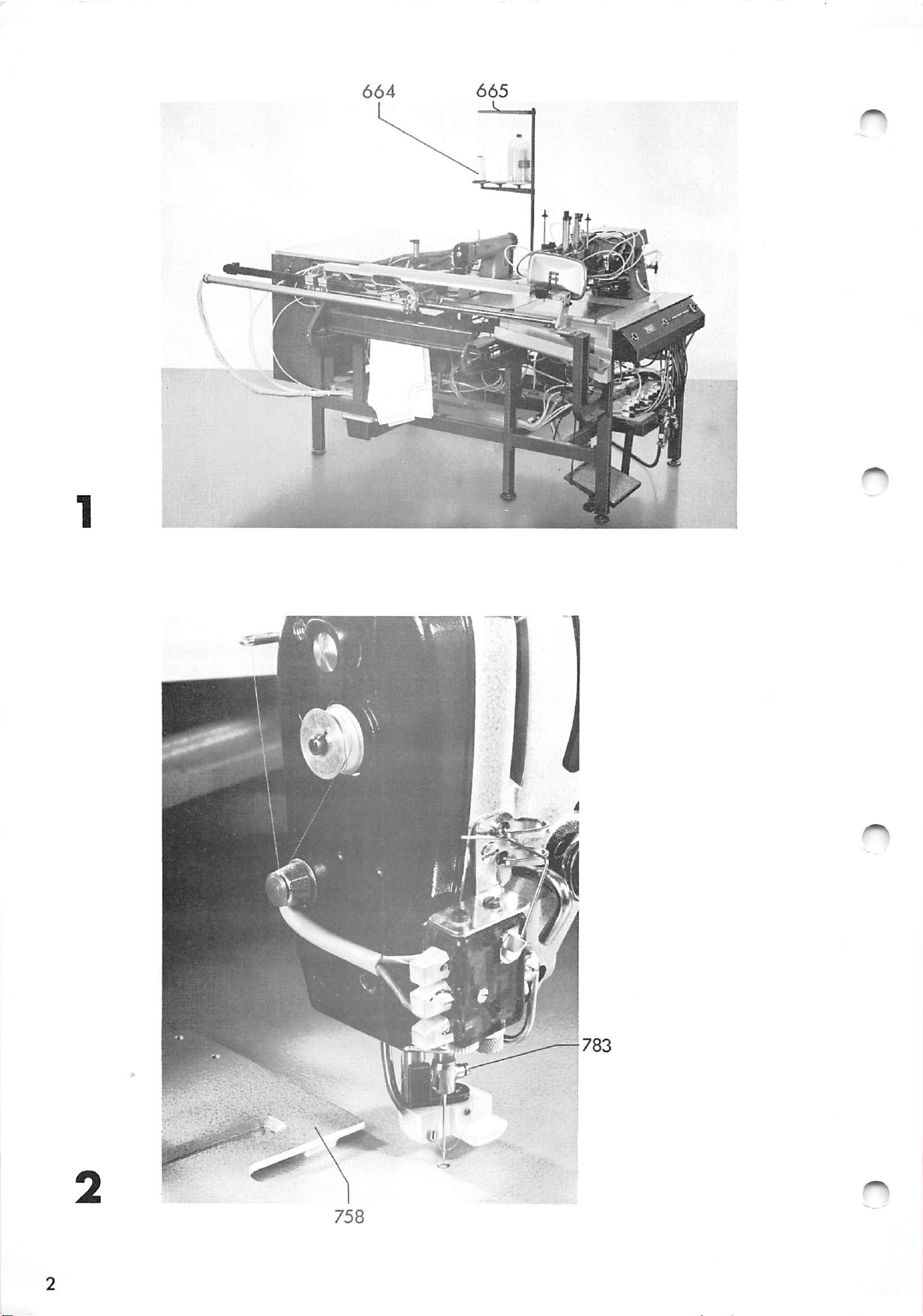
Inserting
The
are
needles
system
sizes
stipulated
Bring
loosen
Push
and
in
turn
template
Re-tighten
80
the
screw
and
the
it
758*
the
to
l^k
needle
needle
new
so
screw
needle
be
needles
90-
783
that
of
used
For
must,
bar
and
needle
783*
each
(Fig,
each
to
remove
the
paragraph
in
the
(e,g,
material
be
the
as
far
long
2)
used.
top
the
sewing
13^
of
needle.
as
groove
R,
it
in
machine
13^
sewn,
its
will
faces
the
kK)
stroke,
given
the
go,
Page 4
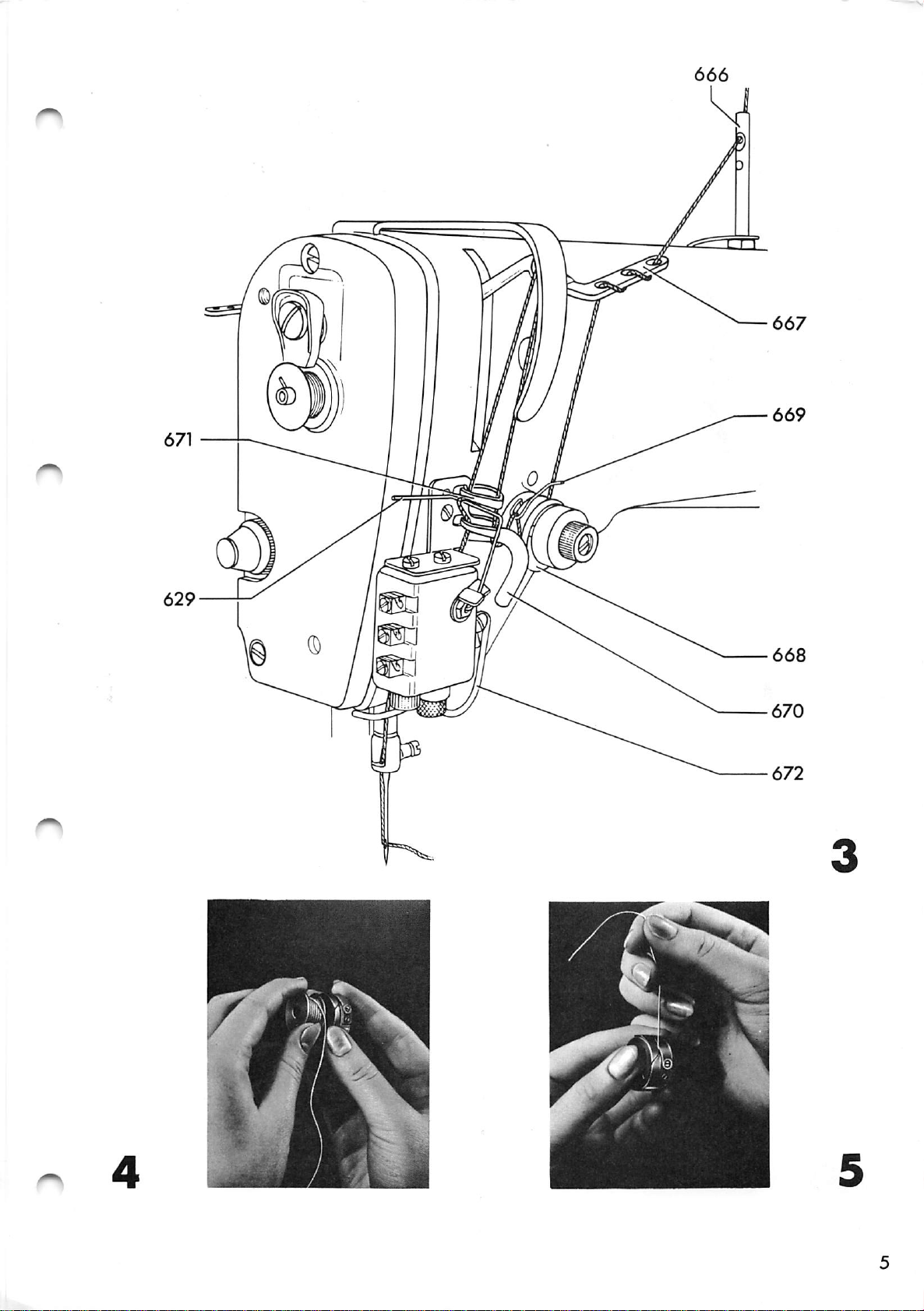
3•
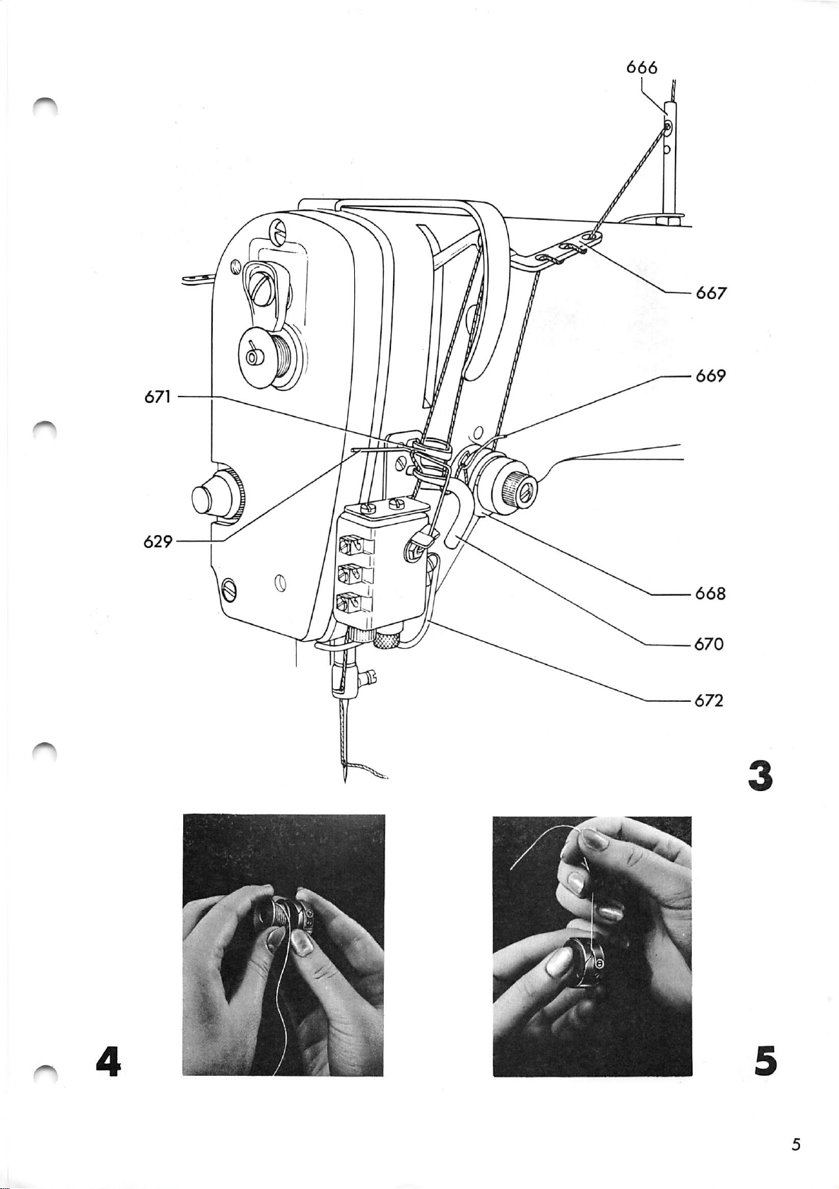
'Threading
the
needle
thread
(Fig.
3)
3.1
Threading
Take
of
the
in
Fig.
of
guide
668
from
guide
of
the
the
thread
wire
thread
needle
Pull
the
needle
machine
the
holes
670
take-up
629
through
from
about
for
thread
1)
667»
below,
and
of
begins
the
in
and
through
Pull
though
lever
through
the
guide
the
3
inches
so
that
sewing.
first
from
the
over
thread
left.
top
the
eye
of
it
time
reel
thread
pin
thread
thread
eye
from
67I
monitor.
672,
thread
does
664,
666
671»
the
so
and
not
between
check
then
right.
that
through
through
pass
guide
to
the
spring
Finally,
unthread
it
through
bracket
three
tension
through
From
it
is
the
the
669i
held
pass
when
holes
the
here,
eye
eye
(665
discs
under
by
the
of
of
the
one
eye
3ead
the
3.2
4.
Thread
Pull
close
old
new
the
sewing
thread
the
to
thread
reel
new
area.
Threading
Insert
clockwise
Pull
tension
Adjust
the
the
the
changing
old
the
on
one
the
the
when
thread
spring
thread
reel
to
the
the
has
Cut
needle.
bobbin
bobbin
tension
stand,
passed
the
the
through
(Figs.
out
on
end
in
thread
by
of
the
of
and
through
end
of
thread
its
case
the
5
and
turning
the
stand.
the
pull
is
6)
needle
new
the
the
(Figs.
so
pulled
slot
screw
Tie
thread,
the
new
that
and
eye
this
old
machine
thread
4,
3^6,
it
(Fig.
under
"X"
and
end
place
thread
turns
4).
(Fig.
to
and
7
the
cut
of
the
and
7)
it
the
the
until
8)
so
that
thread
the
bobbin
(Fig,
8).
case
slowly
drops
when
held
by
the
Page 5
Table
of
contents
Page
INSTRUCTIONS
INSTRUCTIONS
Installing
Adjusting
Pocket
style
FOR
FOR
the
machine
instructions
conversions
THE
THE
OPERATOR
MECHANIC
^6
31
101
Maintenance
Ordering
Lists
and
instructions
control
diagrams
cams
and
sewing
templates
105
111
113
Page 6

INSTRUCTIONS
FOR
OPERATORS
Page 7
♦f
9'
I
Page 8

INSTRUCTIONS
FOR
THE
OPERATOR
Page
10.
11.
12.
1.
2.
3.
k.
5.
6.
7.
8.
9.
Introduction
Inserting
Threading
Threading
Adjusting
Preparing
Loading
Sewing
Setting
bobbin
Winding
Switching
Care
and
the
the
the
the
and
the
the
thread
the
off
maintenance
need.1
needle
bobbin
thread
starting
workpiece
number
bobbin
the
e 3
thread
thread
tensions
the
machine
of
pockets
thread
machine
per
3
k
k
7
7
8
11
l6
17
19
19
13•
Switches
and
buttons
and
their
functions
20
Page 9

LNSTHUCTIONS
FOR
THE
MECHANIC
Page
21.
22.
23.
24.
25.
26.
30.
31.
Installing
Installing
Levelling
Fitting
Oiling
Compressed
Checking
Adjusting
Tools,
Removing
the
the
the
instructions
gauges
the
the
the
reel
air
rotating
sewing
machine
machine
machine
stand
and
and
electrical
other
machine
direction
equipment
connections
27
27
27
28
28
30
33
35
32.
33.
3^.
35.
37. ^
•H
38.1
If)
39.
'lO.
Adjusting
its
Removing
gearcase
Adjusting
Adjusting
S
clearance
Adjusting
Adjusting
Adjusting
Re-fitting
trimming
Regulating
hole
the
needle
the
trimming
cover
the
gear
the
needle
the
needle
the
bobbin
tlie
oil
the
mechanism
the
check
gearcase
hook
in
mechanism
play
rise
bar
case
lubrication
relation
in
the
and
height
opener
valve
cover
to
and
hook
hook-to-needle
and
drive
the
35
36
39
39
^0
'lO
%3
43
kk
Page 10
.^15.
46.
Page
r
Adjusting
t
rG
(0
Adjusting
engaging
the
the
fork
locking
guide
latch
bushing
^7
and
^7
47.
A8.
49. t:
30,
51.
52.
53.
5^1.
55.
56,
60.
61.
62.
63.
6^.
65.
66.
6?.
68.
i
bO
G
I
+>
TJ
(0
0)
rC
o
o
T
0)
+>
(0
rH
a
s
<u
+>
G
•rl
•>
•-
(U
w
73
C
(0 E
fco
G G
•H
-C
H O
C Q)
b E
m
-H
(0
;C
Preliminary
synchronizer
®z^djustment
Adjusting
Adjusting
Final
Adju.sting
adjustment
Adjusting
Adjusting
release
Adjusting
Replacing
Condensed
folding
mechani
Adjusting
Adjusting
plate
Adjusting
Adjusting
Adjusting
Making
arm
a
Centering
Adjusting
the
pocket
the
the
the
the
the
the
the
instructions
station
sm
the
the
the
the
the
sewing
the
the
edge
adjustment
track
roller
thread
of
trimmer
centrifugal
needle
thread
sewing
and
height
pocket
edge
pocket
sewing
test
seam
seam
pattern
ring
lever
catcher
the
knife
thread
monitor
machine
for
sewing
of
plate
folders
holder
template
pattern
of
the
of
the
control
switch
adjustments
template
the
and
on
parallel
control
tension
table
pocket
the
cam
insert
pocket
to
cam
on
k?
k8
A8
51
52
52
55
55
56
57
61
65
65
71
75
76
78
79
79
69.
Adjusting
and
front
the
edge
distance
of
pocket
between
front
seam
L
80
Page 11
70.
Adjusting
machine
in
the
relation
height
to
of
the
the
sewing
table
Page
80
71.
72.
73.
7^1.
75.
76.
77.
7fi.
79.
80.
81.
82.
•H
"o
H
CO
0
rj
C
to
O
r.
r—
(0
Adjusting
Adjusting
Adjusting
cam
Adjusting
Adjusting
Adjusting
to
sewing
Final
Adjusting
Adjusting
Adjusting
Adjusting
Adjusting
adjustment
the
control
the
height
the
safety
the
limit
the
template
the
change-action
motions
the
pneumatic
the
limit
the
pneumatic
the
time
the
motor
of
relays
cam
of
the
clutch
switch
lift
the
sewing
connection
switches
restrictors
switch
bearing
control
of
the
mounting
from
template
lever
cam 85
control
plate
transfer
p4.ate
82
86
86
89
89
90
90
93
96
99
83.
8/i.
'•
86.
87.
90.
91.
Adjusting
Adjusting
Pocket
r
Changing
Changing
Changing
Maintenance
Work
Lvibriediting
on
style
the
the
the
conversions
the
control
the
sewing
the
folding
instructions
conditioning
the
stitch
marking
machine
length
lights
cam
template
station
unit
99
100
102
102
10k
107
108
Page 12

page
95.
lOOo
lot.
102,
103.
Ordering
Information
sowing
Lists
control
templates,
and
Specifications
List
List
Illustrated
of
electrical
of
pneumatic
for
diagrams
parts
cams
ordering
and
sewing
control
templates
cams and
.
equipment
equipment 133
list
112
Ilk
II5
l4l
Page 13
n
/t
Pf
Page 14
0
Page 15
Page 16

^ r1;?t
Page 17

Open
the
the
bobbin
latch
from
of
falling
the
bobbin
out.
case;
Hold
this
the
stops
latch
open,
5•
5.1
insert
the
latch.
you
hear
Ad.lusting
Bobbin
Adjust
"X"
(Fig,
when
Final
to
the
top
and
that
the
it
thread
the
held
adjustment
appearance
bottom
the
threads
bobbin
Press
snap
the
bobbin
7)
by
thread
so
the
case
the
in
tension
thread
that
thread
of
of
threads
are
in
bobbin
place.
tensions
the
the
the
are
interlocked
its
tension
bobbin
(Fig.
tension
seam.
adjusted
case
base,
8),
is
The
lightly
by
case
in
then
turning
slowly
made
tensions
together
the
release
until
screw
drops
according
of
so
middle
the
of
5.2
6,
6.1
the
material
Needle
The
needle
The
For
amount
final
Preparing
Compressed
Before
at
the
of
6
kg/cm
is
adjusted
thread
adjustment
and
starting
supply
2
as
thread
of
air
at
by
tension
tension
starting
connection
shown
tension
the
in
(Fig.
isi-indicated
of
machine
conditioning
turning
Fig,
this
the
and
valve
10)
is
adjusted
tension
machine
always
check
unit
601,
9*
0.2,
on
by
graduations.
see
(Fig,
open
the
The
nut
par,
11)
the
pressure
pressure
"M",
5»1*
valve
Page 18

I-t
the
unit.
The
is
supply
oil
better
and
to
turn
connection
water
levels
the
instead
air
supply
of
conditioning
of
at
on
and
the
conditioning
unit
off
at
0.2
6.2
are
machine
to
drop
water
For
more
Cui'i'ent
Turn
"ON".
The
machine
manual
For
opei'ation
616,
In
the
method
be
dh0cked
is
below
level
details
(Fig.
master
operation.
"AUTO".
following
is
first
switched
the
must
12)
switch
is
in
at
mark
not
see
now
automatic
paragraphs
described.
regular
on.
(see
exceed
par.
602
ready
The
to
oil
arrow
its
12
"l"
to
start,
sequence,
the
intervals
level
in
fig.
mark
(see
"maintenance".
and
press
and
press
manual
when
must
11),
button
is
operation
the
not
and
arrow).
set
button
the
603,
for
7.
7.1
Loading
Marked
The
cuttings,
marked,
60'i,
carried
After
The
pocket
held
facilitate
Lay
the
under
position
plate.
the
workpiece
cuttings
are
positioned
Adjustment
out
by
loading
plate
immediately
re-positioning.
pocket
spring
it
so
on
the
the
blank
clips
that
(Fig.
which
of
cutting,
then
above
(Fig.
13)
the
according
the
marking
mechanic
moves
the
on
the
kk9
and
it
is
13)
location
(see
press
cutting
pocket
against
in
lights
forward
the
of
to
marking
par.
foot
in
plate,
stops
middle
is
8k),
switch
and
order
the
of
pocket
to
down.
push
450,
the
lights
be
7
to
then
is
(Fig.
It
is
it
pocket
12).
Page 19

IBDBQI
Page 20

Page 21

On
striped
or
check
materials
make
sure
that
the
7.2
patterns
This
pocket
the
position
blank
Unmarked
For
unmarked
on
the
tape
then
The
pocket
S
ewing
on
can
be
plate.
is
to
cuttings
surface
(see
positioned
arrow).
cutting
checked
of
be
cuttings
blank
The
the
corrected.
of
according
and
by
operator
cutting
(Fig.
the
The
is
loaded
pocket
means
can
13)
the
positions
table
workpiece
to
as
of
or
with
these
described
blank
the
determine
of
the
black
cuttings
markings.
agree.
winderw
pocket
can
be
adhesive
in
in
whether
marked
are
par.
the
7*1«
S.1
Sewing
\rk\en
and
operated
in
the
workpiece
positioned,
in
Press
pocket
the
press
Press
Folding
descend.
Press
611
out.
manual
the
workpiece.
move
sequence
the
following
buttons
holder
button
button
unit
button
in
cuttings
switches
605
6O6
675»
607
608
610
and
(Fig.
have
and
sequence:
together.
(Fig.
If
correction
"P.HOLD."
"FOLD.
and
table
"FOLDERS":
positioning
13)
been
buttons
l4)
UT."
loaded
This
to
is
(pocket
(folding
insert
edge
pins
are
causes
drop
necessary,
609
folders
612
onto
holder).
unit).
then
move
Press
edge
button
folders
61/
6II
"FOLDERS"
move
out
again.
a
second
time:
11
Page 22

Press
button
607
"FOLD,
UT"
a
second
time:
pocket
pins
in
position
in
place
Press
wards):
to
the
is
set
Press
plate
Press
wards):
to
the
Press
the
holder
retracted.
by
button
the
folding
off
button
moves
button
the
sewing
button
edge
on
at
back
folders,
are
the
the
612
sewing
station.
the
613
6l4
sewing
station.
615
raised
The
folded
workpiece
sewing
"TR.
template
same
"P.PLATE":
to
its
"TR.
FWD".
template
"SEWING":
table
and
pocket
template.
BWD."
The
time.
original
the
insert
the
positioning
is
and
is
held
(transfer
is
transferred
stacker
the
pocket
position.
(transfer,for
is
transferred
sewing
and
now
back
action
action
8.2
After
tion.
Sewing
For
press
After
sewing,
in
working
button
loading
buttons
in
par.
Immediately
next
758
part
cutting
(Fig.
can
automatic
605
8.1
18)
be
is
set
the
the
machine
6I6
"AUTOM".
and
together.
then
proceeds
after
can
be
has
loaded.
off
and
machine
sequence
positioning
The
buttons
picked
picked
the
is
trimming
again
(Fig.
in
automatic
the
operation
automatically.
605
have
up.
As
up
the
in
its
13)
sequence
workpiece,
cycle
been
soon
as
workpiece,
action
starting
described
pressed,
template
the
follows.
posi
first
press
the
next
12
Page 23

Page 24

i
SIIBngBI
Page 25
8.3
Unloading
the
stacker
(Fig.
l6)
8.4
Allow
bar
latch
Remove
Finally,
786
and
stop.
Even
If
the
of
the
may
This
the
be
stacker
qulified
the
sewing
by
786
engages.
the
pull
let
stacking
length
pocket
necessary
adjustment
personnel
its
bundle
knob
bar
of
is
roller.
knob
784
(Fig.
should
action
785
of
7^5
move
17)
the
changed
to
alter
(see
to
towards
finished
forward^
slowly
workpieces
during
the
only
par.
finish,
workpieces.
running
be
81).
then
you
tintil
disengage
back
or
the
operation
carried
to
time
out
pull
latch
its
location
it
of
by
8.5
Disturbances
In
cases
breakage)
The
At
sewing
switched
trimmed
top
of
the
and
its
same
push-button
the
disturbance.
After
removing
monitor
BWD."
before
Now
until
the
it
is
of
the
motor
off
stroke.
(cf.
end
possible
(Fig.
disturbance
sewing
and
immediately,
the
needle
moment,
618
"RESET"
the
par.
the
needle
of
3)
the
I8)
(e.g.
action
cam
drive
bar
thread
light
disturbance,
and
press
is
properly
to
finish
thread
is
interrupted.
motor
the
threads
positioned
monitor
up
button
positioned
formed
the
or
617
to
indicate
check
interrupted
needle
are
are
at
and
the
619
shortly
stitches.
the
thread
"CAM
pocket
If,
too
until
seam.
during
far
the
positioning,
back,
template
briefly
is
the
press
properly
sewing
button
positicned.
template
620
"CAM
moves
FWD".
15
Page 26

When
the
sewing
template
is
in
the
correct
position
^•8
8.7
press
continued
Counter
Counter
This
is
quantities
or
week).
To
zero
Stitch
The
desired
of
the
carried
button
(Fig.
621
a
the
length
control
out
to
counts
means
within
counter,
stitch
by
6l8
the
"RESET".
end
l8)
of
cam.
the
of
each
ascertaining
a
certain
press
length
This
mechanic
The
the
cycle.
sewn
period
trip
is
adjustment
sewing
pocket
set
(see
the
(e.g.
622.
on
par.
action
consecutively.
production
per
the
drive
should
be
8^).
is
now
day
motor
9.
Setting
The
be
set
machine
button
We
find
bobbin,
The
To
set
625
by
repeatedly
the
number
number
on
62'i
exact
counter
(leave
set
wheels
the
number
of
counter
switches
"COUNT."
that
depending
up
number
it
number
pockets
623.
off
to
on
has
623,
pressed
pressing
is
at
to
the
of
(Fig®
200
open
pockets
sewn
When
after
pockets
the
to
be
in)
buttons
the
left
per
with
the
folding
12)
material
ascertained
cover
and
right-hand
are
one
counter
lights
can
626,
set
627.
at
bobbin
full
and
be
and
press
the
Make
"0".
up.
sewn
the
number
side
thread
bobbin
expires,
the
by
sure
and
bulb
with
pocket
trial
zeroing
of
all
(Fig.
can
in
one
and
pockets
that
l8)
the
size.
error.
trip
other
16
Page 27

For
each
pocket
sewn,
the
counter
subtracts
10•
10-1
"1".
is
When
trip
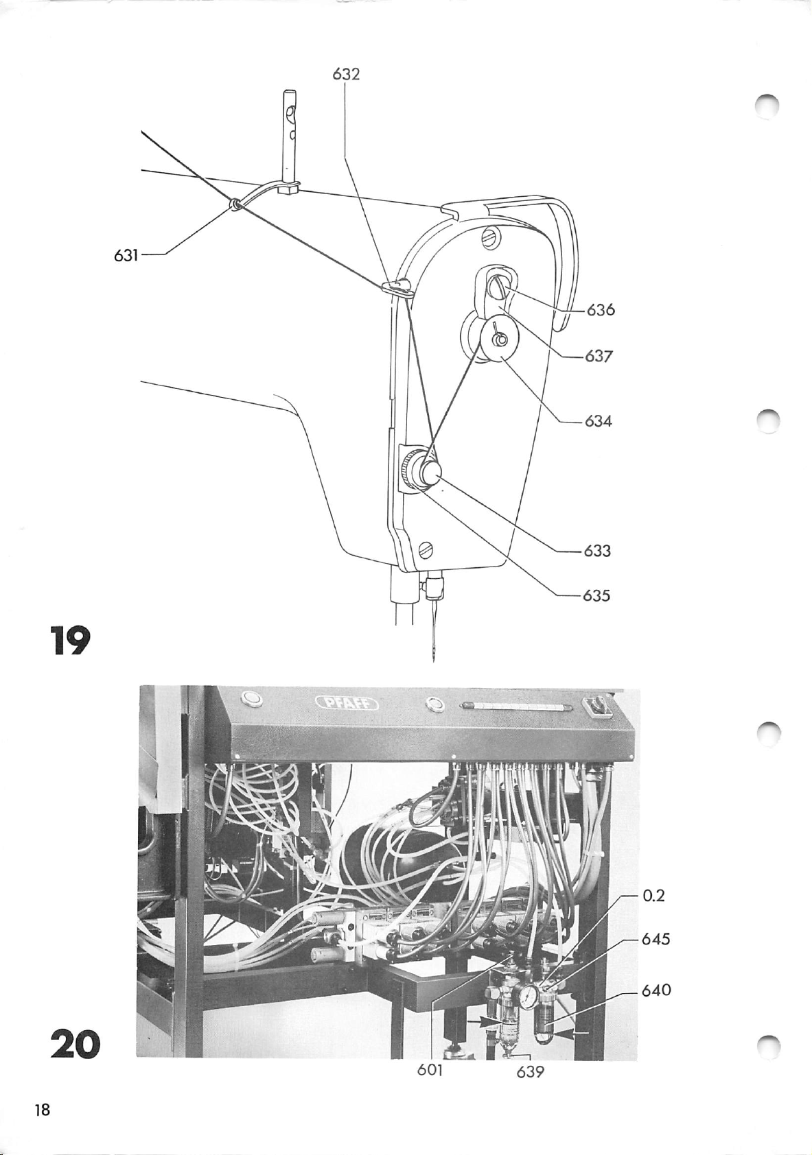
Winding
In
flow
bobbin
Threading
Pass
of
into
632,
thread
When
switched
the
625
order
it
the
the
guide
clockwise
the
bobbin
pressed,
the
to
is
available.
for
thread
top
a
number
coiinter
off
the
has
bobbin
avoid
advisable
bobbin
from
thread
631,
through
around
of
reaches
bobbin
been
the
thread
unterruptions
winding
reel
guide
changed
machine
to
always
bracket
the
tension
times
clockwise
has
(Fig.
664
"0"
to
continues
19)
in
have
(Fig.
through
(665
two
holes
633,
and
be
(see
the
a
I9)
then
around
the
machine
changed*
par.
k)
its
work
full
one
hole
in
Fig.
of
guide
wind
bobbin
and
cycle.
1),
the
10-2
10*
3
634.
Adjusting
The
When
Adjusting
nut
nut
least
winding
635* The
anti-clockwise.
monofil
Tension
runs
even
made
onto
winding
by
possible
633
the
the
thread
or
and
should
the
of
mechanic.
winding
tension
transparent
tension
engaging
middle
the
tension
tension
is
be
adjusted
of
bobbin.
is
increased
threads
should
the
bobbin
the
bobbin.
Adjustment
(Fig.
adjusted
by
be
set.
winder
so
that
19)
on
turning
are
the
This
should
milled
used,
(Fig.
ensures
this
the
19)
thread
be
17
Page 28
Page 29

To
adjust
the
quantity
of
thread
wound,
loosen
screw
For
set
636.
To
downwards.
a
thread
automatically.
•
Switching
When
and
more
it
engage
little.
all
636
lower.
quantity
button
indicator
and
thread
the
If
The
off
638
adjust
set
After
bobbin
you
bobbin
is
the
"OFF"
the
this
adjustment
winder
feel
will
reached,
machine
bulbs
haght
a
resistance,
is
are
lug
higher,
press
now
then
(Fi
g-
pressed,
switched
of
turn
fully
13)
it
the
trip
until
the
trip
for
tighten
turn
is
machine
off.
lug.
less
lug
637
the
the
disengaged
thread
screw
bobbin
set
12.
12.1
Wlienever
thread
pressed
To
completely
switch
Care
Work
If
conditioning
drop
its
To
turns
and
on
the
below
mark
drain
(fig.
a
disturbance
breakage
immediately.
602
to
maintenance
the
conditioning
machine
its
(see
off
20).
switch
"O".
is
unit
mark,
arrows
the
(see
constantly
daily.
water,
par.
off
nor
in
occurs,
8.5)i
the
unit
The
must
Fig.
undo
with
button
machine
in
use
oil
level
the
20).
drain
exception
check
water
tap
turn
638
must
level
639
must
master
the
not
a
of
be
exceed
few
19
Page 30

Screw
in
and
tighten
tap
639
securely.
If
necessary,
12.2
13.
have
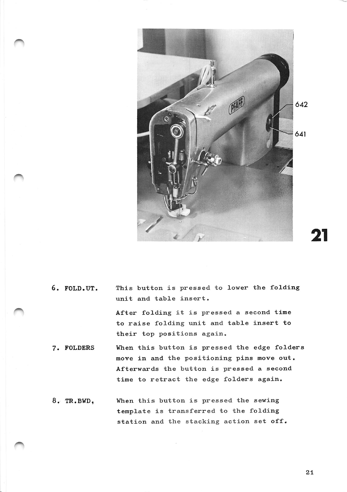
Oiling
the
Regularly
with
The
hook
two
the
Switches
Pfaff
quantity
markings
oil
must
mechanic
(Fig.
oil
sewing
be
through
and
21)
the
the
needle
the
(see
of
such
on
buttons
top
following
machine
top
felt
arrow)
oil
that
glass
hole
and
bar,
for
up
ring
the
64l.
642.
and
the
oil
points
oil:
bottom
on
lubrication
level
If
their
in
container
on
oilpads
the
presser
of
is
between
necessary,
functions
the
of
the
machine
the
bar
sewing
the
top
6^0,
up
13.1
1.
2.ON
3.
4.
HAND
Manual
0 1
0
operation
Master
switches
at
"1".
When
ready
light.
This
Operated
Vlhen
pocket
switch
this
for
button
these
holder
only
button
operation.
is
to
extend
buttons
for
mains
function
is
pressed
drops
pressed
The
the
are
onto
current.
when
button
for
pocket
pressed
the
this
the
manual
plate
table.
The
switch
machine
has
operation
together
following
a
green
is
set
is
of
the
20
Page 31
/
*
This
unit
button
and
After
to
raise
their
When
move
Afterwards
time
When
this
in
to
this
template
station
table
folding
folding
top
and
retract
is
and
is
it
positions
button
the
the
button
transferred
the
pressed
insert.
is
unit
is
positioning
button
the
is
stacking
to
pressed
and
again.
pressed
is
edge
pressed
lower
table
pressed
folders
to
action
a
the
pins
the
the
the
second
insert
edge
move
a
again.
sewing
folding
set
folding
time
to
folders
out.
second
off.
Page 32

9.
10.
11.
P.PLATE
TR.FWD.
SEWING
Pressed
Pressed
to
the
This
sewing
button
to
to
retract
transfer
station.
sets
off
the
the
the
pocket
sewing
sewing
plate.
template
and
thread
12.
13.
Ik.
15.
16.
P.HOLD.
COUNT,
OFF
CAM
CAM
BWD.
FWD.
trimming
Press,
6051
necessary.
top
position.
Lights
expires.
For
switching
This
has
been
template
If
the
held
pressing
if
when
up
button
button
in
actions.
required,
correction
The
when
The
is
removed,
back
too
long,
this
pocket
the
bobbin
off
pressed
to
marked
button.
after
of
bobbin
then
the
in
order
where
"CAM
correction
pushing
the
holder
thread
has
machine.
after
sewing
BWD,"
workpiece
moves
to
be
a
disturbance
to
move
was
has
is
made
in
to
counter
changed
the
left
been
buttons
is
its
off.
by
22
17.
13-2
1.
RESET
Automatic
0 1
When
template
previous
The
the
operation
sewing
cycle.
Master
switches
at
"1".
a
disturbance
switch
position
buttons,
action
only
for
mains
function
has
changed
this
then
been
by
button
continues
current.
when
removed
means
is
this
to
to
The
switch
and
of
the
be
the
following
the
two
pressed.
end
of
is
set
Page 33

2.
ON
When
this
button
is
pressed
the
machine
is
3.
k.
6.
AUTOM
COUNT.
ready
light.
This
operation.
button
Operated
When
the
these
automatic
Lights
for
operation.
to
buttons
up when
sets
extend
operation
the
the
the
are
bobbin
The
machine
pocket
pressed
sequence
button
thread
for
plate.
together
has
automatic
is
initiated*
counter
a
green
7.
8.
9.
10.
OFF
CAM BWD.
CAM
FWD.
RESET
expires.
For
switching
After
button
point
If
the
held
pressing
When
template
two
previous
pressed.
the
end
removing
until
where
button
in
too
a
disturbance
of
The
sewing
long,
this
position
The
the
bobbin
off
a
the
marked
butifeon.
buttons,
sewing
cycle.
then
the
machine.
disturbance
sewing
was
"CAM
correction
has
been
changed
this
action
has
template
left
by
to
press
off.
BWD."
is
removed
means
button
then
be
changed,
this
reaches
has
made
euid
of
is
continues
been
by
the
to
the
the
be
to
23
Page 34

INSTRUCTIONS
FOR
MECHANICS
Page 35

Installing
the
Machine
Page 36

Page 37

21,
Installing
the
machine
21.1
21.2
21.3
22.
22.1
22.2
Before
transit
to
the
responsible.
Lift
the
possible
to
its
It
may
and
the
Levelling
After
feet
To
When
all
until
check
the
six
installing
damage,
carrier
machine
with
location.
be
necessary
sewing
the
installing
this
machine
feet
its
and
a
machine
machine
frame
use
must
and
off
fork
the
has
the
report
to
to
a
precision
stand
machine
the
its
transit
lift
remove
and
(Fig.
machine
and
table
been
firmly
any
Pfaff
truck,
carry
23)
adjust
levelled
check
complaints
agency
support,
and
the
folding
them
are
horizontal.
spirit
out,
on
the
it
for
carry
separately
its
level.
ground.
if
it
unit
threaded
23.
23.1
23.2
Fitting
Fit
to
the
In
certain
at
other
the
the
supplied
right
locations.
reel
of
cases
stand
reel
the
the
stand
sewing
reel
(Fig.
23)
6'l4
machine.
stand
at
may
its
be
location
fitted
27
Page 38

2.k.
Qilinp;
(Fig.
26)
2h,\
2k.2
2^1.3
Before
must
The
hook
window
6/12.
Check
required,
6'i5
"hbchster
be
level
must
the
and
starting
oiled
The
bar,
the
of
remain
6'i
1.
oil
top
filling
Olstand"
(A.5°E, 50°C)
plug
Compressed
645
and
top
and
felt
The
air
with
and
oil
level
up
part
screw
and
the
machine,
Pfaff
bottom
ring
for
between
oil
in
container
the
(max.
number
it
electrical
sewing
on
the
lubrication
the
is
topped
the
container
oil
in
tight
the
oilpads
presser
following
machine
of
two
markings
up
through
conditioning
6^0
by
up
to
level)
280-1-120
(Fig.
connections
of
the
bar
the
removing
the
with
1^4.
27).
points
oil:
needle
(see
sewing
on
hole
unit.
plug
marking
Ursulin
Replace
(Fig.
arrow)
If
II
2?)
25^1
25-2
25.3
Take
int.
the
of
a
dia.)
compressor,
conditioning
supply.
of
at
Set
the
601
of
Check
with
(Fig.
that
hose
The
least
working
the
to
25)
of
which
supply
7
kg/cm
conditioning
make
sure
indicated
appropriate
will
and
connect
unit
0.2
^ine
.
pressure
that
on
length
withstand
it
and
should
of
6
unit.
the
mains
specification
to
the
have a
kg/cm
and
the
pressure
coupling
compressed
on
voltage
plate
size
(6
0.1
pressure
regulator
coincides
647
mm
of
air
28
Page 39

Page 40

2 3.'!
If
the
in
an
mains
electrical
voltage
earthed
current
socket.
should
failures
is
correct
(The
not
may
insert
fluctuations
he
occur.)
too
the
great,
machine
in
otherwise
plug
the
^
26.
26.1.
26.2
26.3
Checking
Turn
603
sewing
master
"ON".
After
at
fan
direction
as
shown
correct
Turn
master
the
The
machine
pressing
6k8
is
by
reverse
rotating
switch
button
in
the
correct
the
switch
motor
button
motor
arrow
the
602
then
runs
when
poles
602
direction
to
"1"
lights
(Fig,
638
(Fig,
housing.
the
in
Fig.
at
to
"0"
and
fan
20,
the
again.
(Fig.
press
up
27),
2?)
The
turns
If
mains
28)
button
green
"OFF"
rotating
it
is
plug.
and
look
in^r.
the
30
Page 41

Adjusting
Instructions
Page 42

T'oolSi
gauges and
other
equipment
^0^
30.1
General
Set
of
10
mm
Set
of
Set
of
Universal
blades
Adjustable
Hammer,
Brass
drift,
Circ-lip
Metal
Tweezers,
Dottle
rule,
tool
kit
screwdrivers
open-ended
alien
keys,
screwdriver
(watchmaker's
spanner
250-gramme
8
mm
pliers,
of
loctite
elbowed
O.3
original
mm
with
spanners
I.5
to
with
screwdriver)
dia.
x
thick
blades
from 6
6
mm
exchangable
250
mm
Seeger
from
to
2
22
to
mm
30.2
Special
Open-ended
Allen
Universal
C-clamp,
key,
tools
part
spanner,
8
mm
gauge,
No.
part
88O
19
mm
No.
137/00
91-129
6o'l-91
33
Page 43

•.f.
Page 44

31.
JRemoving
the
sewing
machine
(Fig>
35)
31*1
31.2
31.3
31.'1
31.5
Press
602
to
0.1
Move
(Fig.
in
remove
(Fig.
Take
panel
(Fig.
To
630
belt
Disconnect
out
remove
(Fig.
while
button
"0"
27).
the
template
36).
the
27
to
36).
the
28)
plug
plug
I^lug
plug
638
and
piston
five
the
drive
downwards
turning
t!io
65^
635
637
656
"OFF",
di
sconnect
rod
758
together
screws
right
belt,
the
following;
for
Tor
Tor
for
of
and
motor
the
the
the
the
turn
master
airline
cylinder
with
6^9*
and
push
remove
press
take
pulley.
thread
synchronizer,
trimming
carbon
switch
coupling
Z
its
cover
it
clutch
off
monitor,
mechanism,
brush
12
frame
the
holder
and
lever
31.0
31.7
32.
32.1
Disconnect
workpiece
at
their
Cut
guide
mounting.
Adjusting
Fig.
Before
13'it
the
37)
size
couplings.
thread
pin,
adjusting,
the
presser
and
the
80
or
air
between
lift
needle
9c.
tubes
(Z
the
insert
20)
in
for
and
the
sewing
relation
a
needle
trimming
reel
new
stand
machine
to
needle
cooling,
mechanism
and
off
its
hole
System
the
its
35
Page 45

32.2
Remove
Fig.
36.
screws
658
and
take
off
faceplate
659
32.3.
32.^1
32.5
32.6
33.
33«1
Bring
take
662
Turn
the
am
Now
needle
wise
out
(Fig.
eccentric
needle
lengthwise
re-position
direction,
After
662.
Finally,
Screw
securely
Removing
(Fig.
Loosen
take
p 1 iers .
off
the
screw
is
proper
tighten
.
the
38)
nut
circlip
needle
37).
is
in
direction.
in
the
adjustment
in,
but
trimming
63O,
bar
66O
stud
the
the
middle
too.
do
grub
remove
676
to
and
663
middle
needle
not
screw
mechanism
with
the
loosen
with
of
fully
fully
the
the
bottom
a
of
bar
its
661
three
of
grub
screws
screwdriver
the
needle
frame
hole
tighten
tighten
and
and
screws
special
its
so
that
in
the
grub
screw
screw
gearcase
673
circlip
stroke,
661
so
hole
the
cross
screw
66O.
66O
cover
and
and
that
in
^
'^
33.2
33.3
33.'i
Push
synchronizer,
at
Pull
lay
Take
698
the
the
same
tlic
the
out
together
trimming
time.
electrical
trimming
the
twelve
with
pulling
mechanism
mechanism
stud
lead
through
screws
the
foam
carefully
67?
out
aside.
678
and
plastic
of
a
little,
remove
inserts.
towards
its
hole
cover
the
and
36
Page 46

m
i
678
698
37
662
630
r
677
38
37
Page 47

II
686
683
01
mm
687
40
685
38
Page 48

^
3^
• Adjusting; the gear play in the
hook
drive (Fig.
39)
3^.1
3^.2
3'i.3
3^1.^1
3'^.5
3'i , 6
35.
Loosen
the
oil
valve
Loosen
shaft
meshed
Loosen
enough
shaft.
Push
and
bring
stroke.
Move
is
a
needle.
In
this
Adjusting
screw
distributor
68l.
screw
bearing
with
screws
to
the
hook
hook
clearance
position
a
allow
the
shaft
the
679
683
68^
very
685
up
needle
of
needle
and
ring
(Fig.
(Fig,
slight
(one
the
hook
against
bearing
0,'l
fully
pull
bar
mm
rise
oil
by
^0)
and
39)
play.
shown
to
hook
to
68'i
between
tighten
and
tube
turning
turn
until
in
be
both
Fig,
moved
shcift
the
bottom
lengthwise
hook
screw
hook-to-needle
680
out
regulating
eccentric
gears
40)
on
bearing
of
until
tip
683.
of
hook
are
just
its
68'i
its
there
and
35.1
35.2
35,3
clearance
Bring
and
hold
gauge
bottom
Place
needle
and
Pull
wheel
c-clamp
bearing.
position.
tighten
the
(part
needle
c-clamp
bar,
out
carefully
is
(Fig.
needle
the
the
The
2,2-mm
No,
push
its
feeler
in
machine
hO)
bar
91-129
bar
686
it
screw.
in
contact
to
thick
bearing,
(part
up
gauge
sewing
is
the
60'i-9l)
No,
against
with
now
bottom
blade
88O
and
turn
direction
the
in
of
of
the
against
1^7/00)011
the
feeler
the
until
needle
its
needle
its
universal
the
balance
bar
stroke
the
gauge,
the
rise
39
Page 49

35»^
In
it
and
needle,
tip
this
and
position
turning
and
needle.
there
it
adjust
so
is
that
a
clearance
the
sewing
its
tip
of
hook
is
beside
0,1
by
ram
pushing
the
between
35«5
36.
36.1
36.2
36.3
36.After
37•
When
the
finger
case
base,
Adjusting
Loostui
bo
moved.
Txirii
conti'ed
Alter
is
liook
688
Adjusting
the
a
clearance
tip
securely.
setting
68?
screws
balance
behind
the
(see
proper
is
then
the
heiglit
adjustment
the
is
in
place
tighten
needle
688
so
wheel
the
of
of
0.8
encircled
bobbin
correct
bar
tliat
needle
the
mm
case
in
the
height
until
needle
between
view).
tighten
opener
the
the
(see
make
slot
two
needle
the
sure
of
screws
(Fig.
hook
encircled
bar
until
needle
the
(Fig.
bar
two
that
the
685.
^1)
tip
k2)
position
bobbin
can
is
view).
there
eye
screws
just
and
37.1
37-^
37-3
T.nsei'l
opener
Loosen
the
when
After
and
a
screwdriver
689
in
screws
bobbin
case
the machine
correct
remove
the
order
69O
and
opener
is
to
in
adjustment
screwdriver.
in
the
see
adjust
reaches
needle
its
fully
slot
motion
eccentric
its
rise
tighten
of
bobbin
more
far
position.
69I
right
screws
case
clearly.
so
that
position
69O
^0^
'lO
Page 50

\
41
689
690
692
42
41
Page 51

43
0.8mm
689
44
O
1
708
695
42
696
Page 52

37-Loosen
the
shaf
screw
bobbin
t.
case
692
just
opener
enough
to
be
to
turned
allow
on
its
37.3
37.8
37-7
37.8
38.
38.1
Ro-position
there
tip
Bring
position
move
contacts
Turn
still
clearance
is
and
the
the
the
in
bobbin
After
692.
proper
Adjusting
Loosen
rod
695
left.
a
the
bobbin
by
bobbin
the
bobbin
contact
of
case
the
screw
of
the
bobbin
clearance
bobbin
turning
case
opener
case
0.3
and
position
adjustment
oil
694
the
centrifugal
case
with
mm
check
of
of
case
the
base
finger.
opener
between
the
case
0.8
base
opener
balance
it
until
finger
fully
valve
check
opener
mm
until
with
the
switch
between
(Fig.
to
its
v\rheel
lug
there
slot
693
tighten
(Fig.
valve
the
to
so
43).
far
"V"
(F
44)
and
that
then
lug
is
in
ig.
screw
the
its
left
a
the
43).
push
far
38.2
38.3
39.
39.1
Move
ance
rod
In
Refitting
mechanism
check
of
696,
this
Ropl£ice
gasket
tight,
screw
on
1
mm
position
the
(Fig.
cover
if
necessary),
then
machine
valve
between
tighten
7O8
tighten
gearcase
4^)
698
on
support
so
push
the
them
that
cover
turn
there
rod
695
screw
and
gearcase
in
the
down
697.
crosswise.
694.
the
is
a
and
actuating
trimming
(change
screws
clear
finger
Also
43
Page 53

39*2
Insert
676
with
stud
the
677
special
its
hole
pliers.
and
replace
circlip
39*3
39Fully
0 •
^0.1
'
).2
).3
AO.'i
Refit
the
three
brushes
Regulating
Mount
an
d
fit
First
will
Turn
and
from
Lay
go,
on
allow
the
a
cutout
the
machine
seconds.
piece
the
are
tighten
the
a
turn
the
hook.
piece
(stick
of
trimming
screws
correctly
tlie
sew^ing
dri
v e
regulating
then
master
the
of
to
A
thin
paper
screws
hook
machine
belt.
out
machine
white
in
place
run
trace
above
mechanism
673»
making
positioned
673*
lubrication
screw
again
switch,
to
paper
at
top
of
the
on
by
run.until
if
necessary)
speed
oil
hook.
on
a
699
half
press
over
should
sure
stf*nd
the
in
(Fig.
in
a
tlie
the
for
bedplate
that
holder
with
as
turn.
oil
needle
and
about
appear
^16)
far
foot
the
is
two
8l2.
motor
as
switch
emitted
plate
allow
10
on
with
it
the
'1O.5
II
out
screw
tlie
a
amount
little,
in.
of
if
oil
it
is
too
small
is
too
large,
turn
turn
screw
this
699
h h
Page 54

677
697
698
45
676
0
673
673
812
o
46
45
Page 55

47
703
702
0,1
\
mm
701
©
J
o
V
ml
\
\
\
700
o
(S)
f
a
3^
o
xim
•
jr=tx
48
703
46
704
705
Page 56

^5.
Adjusting
the
locking
latch
(Fig.
^7)
^5»1
^15.3
h^.h
^6.
^6.1
Bring
disengage
screws
Re-position
there
lever
In
securely,
When
lever
described
is
this
the
703
Adjusting
(Fig,
With
the
screws
705
to
the
700
a
703
position
trimming
trimming
70'l
be
needle
the
trimming
and
crank
clearance
and
the
should
above
the
guide
just
tiirned
bar
701.
702
crank.
tighten
mechanism
drop
may
have
bushing
mechanism
enough
on
its
to
the
mechanism
on
of
0.1
freely.
to
shaft.
top
its
shaft
mm
screws
is
The
to
repeated.
and
disengaged,
allow
of
its
and
so
between
7OO
and
engaged,
adjustment
engaging
guide
stroke,
loosen
that
locking
7OI
locking
fork
loosen
bushing
46.2
46.3
47.
47.1
47.2
Move
703
between
After
securely.
guide
until
proper
Preliminary
track
With
the
ascending
stroke.
Loo
synchronizer
its
the
balance
sen
shaft.
ring
screws
bushing
there
engaging-fork
is
adjustment
adjustment
(Fig.
trimming
wheel
needle
709
track
705
a
towards
clearance
706
of
49T
mechanism
in
sewing
is
4
mm
just
ring
enough
and
tighten
the
disengaged,
direction
past
710
to
locking
of
0.1
mm
washer
707.
screw
synchronizer
until
the
bottom
to
allow
be
moved
latch
704
turn
on
of
the
its
47
Page 57

k7»3
Move
brush
the
the
is
insulated
track
roughly
ring
surface.
1 mm
so
that
from
the
the
left
inside
carbon
edge
of
^7.^
47.5
'1G.
AG.l
'18.3
Hold
so
from
After
Preliminary
Loosen
cam
n
*
Move
the
stop
of
Bring
and
that
712
cam
the
hold
the
the
correct
screws
the
ring
control
the
balance
the
carbon
end
adjustment
to
be
cam
and
the
713
needle
the
wheel
of
the
adjustment
711
just
moved
laterally
bedplate
to
the
cam.
bar
balance
brush
insulated
on
right
wheel.
to
and
is
fully
of
the
enough
its
so
that
is
the
turn
roughly
shaft.
2.5
and
bottom
track
surface.
tighten
control
to
allow
the
mm.
up
against
ring
17
mm
screw
cam
control
clearance
Then
of
its
710
away
(Fig.
move
the
stroke
709
50)
between
boss
'18.^
^18.5
'19,
^9*1
Turn
points
bedplate.
cam
control
is
Tighten
Adjusting
With
needle
the
roughly
Make
up
against
screws
the
trimming
bar
to
cam
roller
the
712
towards
sure
the
711
mechanism
top
so
the
that
stop
securely.
lever
of
that
the
its
the
front
boss
ring.
(Fig.
disengaged
stroke.
tip
edge
of
51)
of
the
its
of
control
bring
lobe
the
the
iiQ
Page 58

Page 59

•MM
i
IIUUi
52.1
50
52.2
Page 60

Looson
^
715
between
and
SO
roller
screws
that
the
there
inner
716.
7'1^
and
is
surface
re-position
a
clearance
of
control
roller
of
0,5
cam
lever
roin
712
49.4
49.5
49.6
49.7
50•
Now
roller
shaft.
tigliten
ascending
of
its
Pull
go
edge
In
To
must
into
If
49*4
Adjusting
crank
and
of
this
check
be
the
necessary,
and
lever
Turn
needle
stroke.
push
the
position
this,
possible
cam
49-5-
the
the
can
the
717
roller
cam
track.
two
still
balance
bar
downwards
track.
tighten
operate
to
repeat
thread
screws
is
716
easily
the
catcher
71^1
be
turned
wheel
4
mm
as
against
screws
engaging
push
adjustment
far
until
past
(Fig.
so
as
the
7l4
on
fork
the
that
its
the
the
it
outer
securely.
7O6.
roller
in
51)
the
bottom
will
It
paras.
50.1
50.2
50.3
50.4
50.5
With
and
adjust
its
tip
(Fig.
Fully
Position
of
its
Operate
wheel
front
Loosen
catcher
position
the
points
52.1).
tigliten
stroke.
enging
until
position.
screws
719
needle
thread
the
thread
is
finger
plate
to
screws
needle
fork
720
positioned
693
catcher
the
4
706
catcher
and
^s
removed,
middle
7lS«
mm
past
and
turn
shown
719
719
crank
in
laterally
of
the
turn
relation
in
loosen
the
bottom
the
reaches
71?
Fig.
screws
needle.
balance
so
to
52.2.
its
so
that
718
that
51
Page 61

50,6
Finally,
tighten
screws
720
securely.
51.
51*1
51.2
51.3
51.^
51.5
Final
rosition
stroke
Turn
there
of
thread
finger
Loosen
the
distance
off
721
Chock
according
After
adjustment
the
and
the
balance
is
a
693*
screws
and
roller
adjustment
needle
operate
clearance
pul3-off
between
the
lever
to
par.
711
of
engaging
wheel
721
and
catcher
715
49*6.
tighten
the
of
the
mm
in
and
turn
for
control
past
sewing
2 mm
the
control
back
tip
correct
screws
the
fork
between
middle
edge
is
k mm.
cam
bottom
706.
direction
cam
of
adjustment
711
(Fig.
the
of
712
thread
securely.
53)
of
its
until
back
position
until
edge
pull-
52.
52.1
52.2
52.3
Adjusting
Take
If
and
so
to
out
necessary
polish
that
7 nim
surface
Bring
and
re-fit
Adjust
cutting
and
that
catcher.
the
the
screw
its
from
as
edge
the
the
the
cutting
shown
needle
the
knife
trimmer
722
re-grind
cutting
the
knife.
.and
knife
(Fig.
centre
in
bar
so
the
is
knife
edge
Fig.
to
that
needle
the
edge.
line
the
centred
51)
knife,
is
5^^
the
(Fig.
and
Then
at
6f
• 1 •
bottom
clearance
is
a
3*5
over
5^0
remove
remove
bend
distance
its
of
nim
the
the
the
the
supporting
its
between
(F'ig.
thread
knife.
burr
blade
of
stroke
6.5
its
52
Page 62

706
o
pf®
(S)
(JH
o
ii=a
31
693
715
712
Amm
53
3,5mm
i
6,5-7mm
r
54.1
54.2
54.3
53
Page 63

mm
724
723
OJmm
55
703
728
727
56
726
Page 64

The
from
(Fig.
right-hand
the
recessed
5^.3)
edge
edge
of
the
of
knife
the
thread
must
not
catcher
protrude
•
5'2.4
52.5
33.
53.1
53.2
After
The
knife
719
and
thread
of
the
catcher
Adjusting
Loosen
of
centrifugal
clearance
bushing
Re-tighten
allow
on
its
adjustment
must
be
in
is
properly
cutting
719
according
the
screws
of
725.
screws
centrifugal
shaft
tighten
be
light
edge.
centrifugal
723
switch
1
mm
by
hand.
absolutely
contact
cut
If
to
and
adjust
72^
between
7231
switch
screw
at
any
necessary,
paras.
switch
so
the
but
only
72^
parallel
with
place
the
that
switch
to
722
50,1,
enough
be
securely,
it,
over
re-adjust
(Fig.
lateral
there
turned
so
and
to
and
that
53)
is
to
catcher
the
50.2.
position
a
the
width
53.3
53.4
54.
54.1
54.2
Adjust
that
left-hand
is
locking
passing
After
Adjusting
Loosen
Turn
the
its
the
ascending
stroke.
the
centrifugal
insulated
the
adjustment
the
nut
726
balance
lever
carbon
needle
and
needle
703
surface
tighten
re-tighten
wheel
switch
is
brush
thread
in
is
released
screws
sewing
4
mm
by
of
track
(Fig.
tension
it
past.the
turning
while
49).
723
slightly.
direction
ring
securely.
release
bottom
it
the
710
until
so
(Fig.
of
56)
55
Page 65

5'i.3
operate
the
thread
its
far
released.
the
engaging
its
stroke.
engaging
tension.
left
position
The
shaft
fork
releasing
When
has
706
engaging
the
action
covered
(Fig.
tension
53)
shaft
should
should
roughly
and
look
727
begin
half
be
at
is
fully
when
of
in
'^
^k,k
5'i • 5
55•
5''.1
55»2
To
adjust,
rod
is
the
tension
is
moved
release
After
726.
Adjusting
If
the
the
sowing
Thus,
breaks
other
Adjust
roughly
position.
moved
in
action
correct
setting
the
monitor
off
sewing
stop
5
mm
re-position
towards
release
the
opposite
is
adjustment
the
thread
of
action
the
sewing
disturbances
732
so
from
the
action
retarded.
monitor
the
will
must
that
eye
pull
thread
be
be
action
the
67I
rod
bedplate
is
direction
securely
(Fig.
monitor
interrupted
adjusted
when
occur.
thread
when
728.
advanced.
tighten
in
When
(see
the
57)
is
so
thread
wire
its
arrow)
When
tension
too
too
that
is-held
far
this
it
nut
sensative,
frequently.
it
breakage
left
only
or
55-3
55*^
55-5
Loosen
730
Make
tighten
Turn
stop
Bend
eye
must,
eye
are
sure
knurled
732
wire
671*
when
671.
screw
closed
screw
only
Whe
that
629
in
729
when
wire
729*
screw
lightly.
upwards
tlie
its
and
turn
wire
629
731
machine
resting
so
has
in
the
629
no
so
that
is
threaded,
position,
disc
is
that
it
resting
lateral
wire
is
so
0.1
be
that
play,
629
wire
held
on
mm
contacts
the
and
strikes
away
629
against
stop.
from
56
Page 66

732
729
57
55*7
56.
56.1
56.2
56.3
The
on
action
delayed
resistance
Replacing
Lower
studs
Replace
it
with
Retract
insert
in
the
is
the
onto
cover
its
the
sewing
template
action
set
the
sewing
the
five
piston
r23
in
between
sewing
machine
rubber
panel
screws
template
fixture.
of
the
machine
2?
rod
the
thread
control
1/2
and
with
mountings.
on
the
649.
of
cylinder
758
with
1
(Fig.
its
table
monitor
box.
second.
58)
four
Z12
its
This
hinge
and
frame
is
sectire
and
set
57
Page 67

w.
Page 68

56.A
Insert
synchronizer,
carbon
the
brush
connectors
the
trimjning
holder.
for
the
thread
mechanism
monitor,
and
the
the
56.5
56.6
Rc-connect
mechanism,
for
needle
Re-fit
the
the
the
cooling.
drive
air
tubes
workpiece
belt.
for
presser
the
trimming
and
that
59
Page 69

1 »
(B O
Page 70

60.
Condensed
instructions
for
adjustments
on
60.1
60.2
60.1
folding
(Fig.
bU
Adjustments
mechanisms
which
sequence.
means
condensed
a
have
of
detailed
Adjust
level
with
Position
on
the
Posit
positioning
of
Jon
guiding
station
to
The
obtaining
the
the
table
the
63)
on
the
consist
to
be
sequence
instructions
description
table
tlie
tabletop.
pocket
insert.
pocket
pin
lines
and
carried
insert
holes.
drawn
sewing
folding
of
many
proper
plate
plate
out
given
below
of
so
This
on
template
and
sewing
individual
in
here
adjustment.
are
each
adjustment.
that
so
tliat
arm
parallel
is
checked
the
table
a
certain
is
followed
it
it
mechanism
template
items
the
The
is
exactly
rests
with
by
insert.
best
by
flat
the
means
60.'1
60.5
60.6
60.7
Adjust
edge
of
Position
the
pocket
from
With
the
tlie
folders
jilate.
fabric
Position
pins
do
adjustment
in
the
tlie
pocket
the
the
plate
positioning
folding
parallel
Their
thickness.
the
not
is
following
table
pocket
clearance
edge
strike
checked
plate
insert.
plate
edges
unit
to
the
folders
the
position:
folding
pocket
edge
positioning
pin
down,
with
parallel
arm
are
holes.
underside
is
set
so
edges
holder
folders
at
adjust
the
unit
to
laterally
equal
according
that
of
the
folding
down
up
forward
pins
the
distances
the
of
the
slots.
up
outer
so
edge
the
pocket
to
positioning
station
that
the
This
(>0.0
Atljust
to
table
between
on
the
the
insert
the
material
pocket
angle
hoj-der
and
strips
thickness.
pocket
so
and
that
plate.
pocket
it
The
is
plate
parallel
distance
depends
61
Page 71

bO.
9 1^0
The
plate
chock
pocket
aJJ
the
blank
the
mechanism,
must
way
round.
hug
fold
the
one
edge
pocket
of
the
blank.
pocket
bO.lO
•60.11
b0.i2
60.13
Position
remains
movements
Now
make
incorrect,
i
nvo1V
The
seam
the
pocket.
Remedy:
The
seam
e
d.
the
in
the
of
a
sewing
the
pattern
cidjust
pattern
sewing
middle
the
three
stop
template
template.
test.
following
is
parallel,
at
is
parallel,
of
If
end
its
the
of
so
slot
seam
types
but
transfer
but
that
throughout
pattern
not
too
the
of
centred
cylinder
high
needle
fault
or
is
still
may
on
accordingly
too
be
low
60.l'l
60.15
Jiemedy:
The
Remedy:
It
m.ny
tlie
by
step.
a.lwavs
seam
.above
set
or
pattern
turn
hapjien
faults
Parallel
be
m.ade
the
back.
\
the
that
i'irst.
entire
is
-/
entire
.a
occurs.
.adjustment
folding
not
parallel
folding
combination
If
so,
of
station
with
/
station
of
they
seam
the
two
must
to
farther
pocket.
.accordingly
or
three
be
pocket
forward
removed
must
of
step
62
Page 72

Page 73

|5|
DB
733
15
iq
0
—
f
< >
IIp ft
Xi
65
64
Page 74

•
Adjustinj;;
the
height
of
the
table
insert
(Fig.
6'i)
61.1
61.2
61.3
GlJi
61.5
61.()
62,
62.1
Loosen
Turn
insert
To
its
After
Move
and
droi^
If
the
chock
top
adjustment,
the
allow
quickly
necessary,
Adjusting
(Fig.
66)
Loosen
366
can
locknuts
piston
6O9
is
this
position
table
it
the
screws
just
733
rods
flush
setting,
insert
drop
and
repeat
pocket
73^1
be
ma^d.
(cylinders
of
with;tabletop
and
place
tighten
by
its
freely.
adjustment
plate
so
that
move
to
the
screws
its
own
the
Z k
cylinders
the
table
a
ruler
top
weight.
6l.2.
and
pocket
two
and
until
at
both
insert
on
it.
733
securely.
position
It
plate
bearing
Z
must
5).
table
ends.
to
again
arm
blocks
62.2
62.3
62.Push
Alter
the
in
Move
line
in
(Fig.
the
pocket
lengthwise
the
at
point
tlie
line
with
65).
height
plate
pocket
pocket
and
"P"
tlie
of
lies
crosswise
plate
in
plate
two
the
Fig,
rear
two
parallel
to
its
back
bearing
on
direction.
front
65
on
the
until
positioning
blocks
the
position
table
its
table
front
pin
so
insert
and
insert.
edge
holes
that
make a
is
65
Page 75

'62.5
'Draw
and
holes;
another
(between
must
be
line
at
the
exactly
point
lines
the
"P".
and
same
The
the
(Fig.
distance
positioning
65).
x
pin
62.6
62.7
62.8
62.9
62.10
()2.11
If
tlie
366
so
the
row
repeat
After
screws
Loosen
parallel
Fully
Loosen
and
position
arm
laterally
plate
positioning
In
this
fixing
tighten
Move
screws
front
from
the
the
distances
that
items
of
positioning
pocket
62.3
adjustipent
73^
securely.
screws
to
the
tighten
screws
clamp
are
at
the
pin
position
rings
screws
738
edge
positioning
737
pocket
and
of
vary,
plate
to
of
735
and
outer
screws
736
so
the
(Fig.67)
block
that
same
holes.
tighten
np
736
re-i)osition
(Fig.
plate
pocket
re-position
pins.
62.5*
the
pocket
position
edge
735
the
distance
against
to
pin
arm
of
again.
and
3'*^^
edges
screw
67)•
its
cylinder
plate
holes
3ij7
To
the
of
clamp
front
is
check
plate
the
screw
the
of
from
8l'i
is
as
bearing
parallel
this,
arm,tighten
pocket
table
8l4
pocket
the
the
securely,
and
position,
Z1
the
same
the
side
insert.
(Fig.
pocket
rows
so
blocks
plate
plate
fully
that
distance
edges.
to
69)
of
push
loosen
the
62.12
62.13
62.1^1
Make
tighten
Loosen
its
front
Turn
clearance
station
top
position.
sure
locknut
stop
that
screws
position
screw
of
housing
the
738
739
3 mm
when
38O
between
cylinder
securely.
and
move
(Fig.
in
or
the
69).
out
screw
pocket
is
the
not
pocket
until
plate
371
turned,
plate
there
and
is
the
at
and
is
to
a
folding
its
66
Page 76
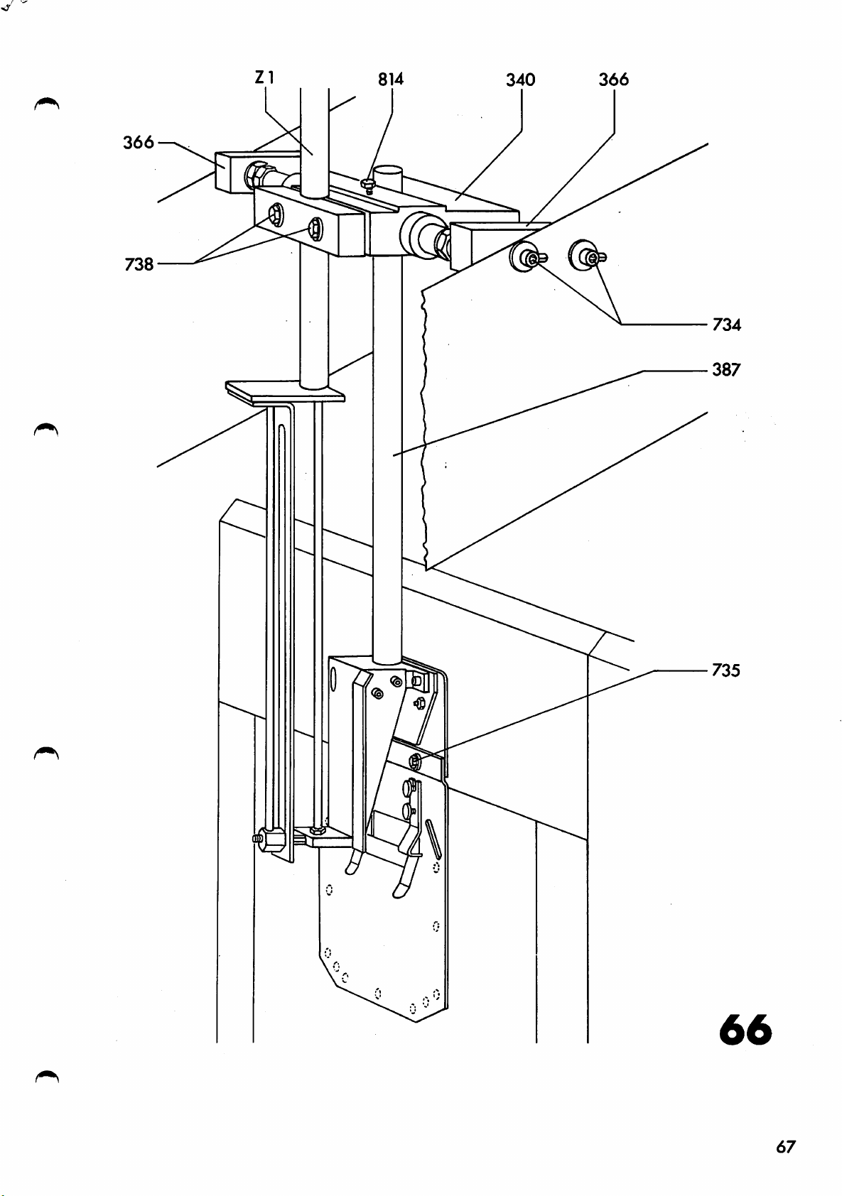
366
738
66
67
Page 77

67
736 737
340
737 736
381
68
380
739
Page 78

371
69
69
Page 79

378
379
/
0,3
0,7
mm
Z17
o
hs
Page 80

02.13
Tighten
plate
locknut
to
its
rear
739
position.
a
little
and
move
the
pocket
62.16
62.17
62.iB
62.19
62.20
63.
Loosen
so
that
the
bd
In
739
end
and
this
securely.
Move
loosen
With
in
or
pocket
material
to
move
In
this
Adjusting
the
the
out
screw
there
of
69)•
position
pocket
locknut
piston
so
plate
thickness.
the
position
the
is
screw
that
and
workpiece
edge
and
a
3^0
tighten
plate
379
rod
the
securely
push
clearance
and
(of
extended,
the
table
It
folders
clamp
screw
to
its
cylinder
distance
must
with
stop
of
front
is
still
ease.
tighten
(Fig.
bracket
0.3
block
7^A0
ZI7)
turn
between
equal
and
position
stop
be
locknut
71)
mm
3^0
in
to
possible
3^1
between
(Figs.
locknut
Fig.
nut
the
the
379-
upwards
and
70.
37^
(>3 • 1
63.3
Move
four
tlie
screws
Ro-position
edge
at
folders
the
Tighten
Loosen
that
are
(see
and
the
at
dimension
re-tighten
side
same
the
locknuts
folder
equal
edge
7''1
•
mounting
are
distance
four
7'i3
blades
distances
"x").
locknuts
folders
parallel
screws
and
Extend
plate
from
7^1
turn
in
from
7^3•
back
7'i2
with
it
securely.
their
the
the
at
the
and
so
that
the
both
piston
retracted
pocket
piston
loosen
pocket
sides.
the
plate
rod
rod
the
side
plate
so
position
again
71
Page 81

63.^
Loosen
745
bottom
Their
the
ndjxistnient
locknuts
(Fig.
position
distance
thickness
72)
tighten
744 and
so
that
are
from
of
the
the
parallel
the
material
the
adjust
folder
pocket
locknuts
the
to
plate
(up
height
blades
the
pocket
depends
to
O.3
securely.
in
mm).
of
their
plate.
stops
on
After
63•5
63.6
Loosen
folder
slots
it
i s
Also
are
(see
very
in
in
sequence
proper
make
in
dotted
important
the
the
screws
blades
and
are
inserted.
sure
line
tirst
first
(see
adjustment
7'i6
so
not
with
lines
stage
and
below:
that
that
the
for
second
(Fig,
struck
the
corners
in
Fig.
the
or,
operating
tighten
72) and
pins
by
sides
edge
in
stage
re-position
747
are
the
pocket
of
of
the
73).
three-stage
screws
This
folder
of
sequences).
free
the
folder
pocket
adjustment
blades
the
folding
746
securely.
the
in
their
plate
sequences,
when
blades
plate
extended
After
is
1 o
2 d
3 e
a—^
Operating sequence of the edge folders
-i-b
! 1
— b
1
2 d + e
3
a+b+c
—1
o-hh
b
y,.y
d e
M.
c
1 a♦b
2 c
3 d
+e
a-^r--|^b
j 1
d—e
"T"
C .
72
Page 82

71
max.0,3
mm
72
73
Page 83

73
748
748
748
£ 2
<
751
755 752
754
Page 84

•63.7
.Move
position
rods
the
(Fig.
front
and
73)•
edge
loosen
folders
locknuts
to
7^^
their
of
extended
the
piston
63.
63
*9
Gh.
G'l . 1
_
6^1.2
Turn
are
the
at
pocket
tighten
I'o
adjust
turn
that
the
shows
screw
the
pocket
Adjusting
Move
loosen
Turn
is
ppposite
covering
the
piston
raised,
this,
its
bottom
held
in
piston
distance
plate
tlie
timing
the
pocket
locknut
rests
insert
place.
(cf.
locknuts
the
817
style,
posssible
the
rod
then
direction
a
position
rods
"x"
timing
on
of
pocket
holder
7^9*
750
turn
on
pocket
so
that
from
item
63.3)-
7^8
of
the
penumatic
the
sequence
see
table
operating
holder
to
until
the
until
the
pocket
cutting.
the
pocket
the
the
front
In
securely.
operating
delay
on
sequences.
(Fig.
its
bottom
the
pocket
piston
the
foam
plate.
edge
edge
this
valve
correponds
page
7^0
rod
plastic
When
cutting
folders
poisiton
sequence,
72
which
position
holder
in
To
the
must
of
816
the
check
holder
the
to
so
be
and
is
in
6^1.3
G'l .'1
G'l,^
G^i.G
In
this
With
screws
Adjust
so
that
After
nuts
and
the
proper
752
correct
position
pocket
751
the
it
securely.
and
the
pocket
;|.ies
adjustment
if
necessary.
tighten
holder
four
holder
perfectly
Check
locknut
down,
locknuts
by
tighten
the
l.oosen
turning
flat
adjustment
7^9
752.
on
screws
the
screws
the
securely.
two
table.
751
again
753
and
lock-
75
Page 85

'6^1.7
'Move
the
out
the
pocket
screws
pocket
holder
75'^
plate
and
to
its
remove
to
its
bottom
angle
front
position
position.
strips
and
Take
755.
6'l.d
6^.10
6'l . 1J
(>^J.12
6^.13
Loosen
holder
of
the
In
this
Replace
and
screw
Lilt
and
Push
the
In
fold
hug
necessary,
the
lower
the
fabric
order
one
the
the
two
so
that
pocket
position
angle
them
pocket
the
angle
and
to
pocket
pocket
repeat
screws
its
plate.
strips
in
holder
strips
securely
check
plate
edges
tighten
finger-tight.
holder,
all
cutting.
the
751
and
are
screws
755»
turn
flush
insert
insert
again.
lightly
tighten
and
adjustments
The
all
above-mentioned
the
folded
way
751
screws
a
pocket
screws
round.
the
with
securely.
evenly
from
pocket
adjustments.
pocket
those
75^
cutting
against
75'l.
bl
to
If
6k^
must
^5.
65.1
65.2
65.3
Adjusting
Loosen
tighten
moved
Turn
needle
Turn
is
Turn
tip
of
seam.
control
the
in
the
of
the
screws
them
with
is
balance
the
control
the
slot
the
sewing
75^
so
difficulty.
cam
at
the
slot
needle.
from
that
of
and
759
starting
wheel
the
cam
It
the
template
grub
template
(Fig.
point
until
template*
by
hand
must
beginning
screw
758
75)
the
again
remain
(Fig.
by
of
to
757,
can
hand
the
tip
and
in
the
76)
of
the
and
be
until
seam.
watch
end
re-
the
middle
of
the
needle
the
the
7b
Page 86

i
76
Page 87

65.
Lengthwise
by
re-positioriing
this,
the
needle
tlie
needle
turn
or
the
tip.
to
crosswise
the
control
After
the
top
deviations
sewing
cam
each
of
its
template.
by
check
stroke.
hand
are
and
always
corrected
To
check
watch
move
65.6
6b,
bb.l
()b.l5
After
grub
Making
Place
and
If
the
there
The
the
correct
screw
a
a
make
previous
are
seam
poclvot.
757
sewing
workpiece
a
sewing
only
pattern
adjustment
securely.
test
and
test.
adjustments
three
is
a
pocket
faults
parallel,
tighten
have
which
blank
but
screws
been
may
not
in
made
now
centred
756
the
and
machine
correctly
occur;
on
66.The
Remedy:
seam
low.
Remedy:
-X
adjust
accordingly
pattern
set
the
forward
stop
is
entire
or
at
(see
parallel,
back
end
item
folding
(see
of
but
item
transfer
67).
too
station
68).
high
farther
cylinder
or
too
78
Page 88

66.5
.
The
pocket.
seam
pattern
is
not
parallel
with
the
66.
67•
67*
67.2
Remedy:
()
It
may
three
must
adjustment
first.
Centering
(Fig.
1
Loosen
the
its
line
roller
Make
if
required.
of
be
77)
stop
of
a
liappen
the
sewing
turn
accordingly
the
above
removed
of
the
two
in
or
15O
rod
131»
the
that
step
seam
seam
locknuts
out
must
test
entire
(see
a
combination
faults
by
to
pocket
pattern
as
be
and
folding
item
occurs.
step.
on
l'l8
requiced.
aligned
adjust
must
and
68)
The
the
with
the
station
of
760
The
two
If
so,
parallel
always
pocket
and
axis
the
stop
or
they
be
turn
of
centre
again
made
67.3
68.
68.1
68,2
After
l'l8
and
Adjusting
pocket
Loosen
and
disconnect
Loosen
I'olding
on
the
adjustment,
760.
the
edge
the
the
station
sewn
(Fig.
four
two
pocket.
seerni
screws
air
knobs
so
securely
pattern
7^)
coupling
278
that
76I
the
tighten
parallel
of
and
side
0.1
(Fig.
re-position
seam
locknuts
stops
is
to
the
28).
parallel
7(>2
the
79
Page 89

'68.3
After
the
screws
re-positioning,
frame
one
76I.
after
the
push
other
the
side
and
stops
fully
up
tighten
against
68,^
(>8.5
69•
69.1
69*2
69.3
Re-tighten
0.1
and
If
necessary,
according
Adjusting
Jroiit
Loosen
station
the
side
Check
After
edge
screws
same
s eams.
this
correct
knobs
make
to
the
of
lengthwise
distance
adjustment
278,
a
sewing
re-position
items
distance
pocket
703
adjustment
68.1
and
so
from
re-connect
test.
the
to
68.^1.
between
(Fig.
re-position
that
the
by
79)
the
pocket
means
fully
air
folding
front
the
front
edge
of
a
tighten
coupling
station
seam
folding
seam
as
sewing
screws
again
and
is
the
test.
763.
70.
70.1
70.2
70.3
70.'1
Adjusting
relation
Move
Remove
Using
the
ir
ill
its
temxjlate
sewing
necessary,
item
I.eight
screws
a
ruler,
31,
the
to
machine
by
height
the
table
758
6^j9
check
disconnect
remove
adding
to
c\nd
is
the
of
the
(Fig.
the
folding
cover
whether
level
all
sewing
or
removing
sewing
80)
station.
panel
the
with
27.
bedplate
the
connections
machine,
spacers
machine
table.
and
in
of
as
adjust
as
described
required.
80
Page 90

131
150
148
1 !
- 1
1 .
1 \
1
H
it n
77
150
131
.\i
\
278
1/-
78
81
Page 91

79
71.
71.1
71.2
Adjust
mlju.ste.l l,y
however,
owing
external
to
injz:
the
that
to
damage
influence.
he
made
control
means
the
in
when
Position the control
'im
sewing: ninchine
i^!!„
and'shaft
and
pivot
^37,M
bearing
needle
mm
respectively.
the distances
cam
liearing
o( a Kause.
position
transit,
The
of
following adjietment
the gear
cam
'lO,
and
are
so
drive
all
needle
Jt
the
or
to
motor
that
shaft
aligned.
between
(Fig.
may
happen,
cam
is
some
has
other
been
the centre
76'l and
arm
must
bo
81)
is
exactly
disturbed
also
replaced.
lines
the
pivot
26U.7
mm
rv
d2
Page 92

R
Page 93

82
471
766
759
I
II
s
83
770
768
84
Page 94

71*3
'If
765,
gear
71v2
these
re-tighten
motor
is
distances
until
obtained.
them
the
are
a
position
incorrect,
little,
loosen
then
described
turn
screws
the
in
item
71*^
71.5
.7^•
72.1
This
help
obtained
No.
95-bl2
After
Adjusting
Using
height
upper
cam
759
there
template
767
when
"transfer"
bearings
binding.
adjustment
of
a
special
from
533-^5.
proper
the
a
32-iiim
of
threaded
and
lower
by
roughly
is
a
clearance
frame
the
has
of
is
gauge.
PI,
Kaiserslautern,
adjustment
height
open-ended
control
carrier
change-action
taken
the
control
best
of
bushing
the
of
place.
carried
The
tighten
the
spanner,
arms
same
roughly
101
arms
gauge
control
52
clear
amount
and
from
The
must
out
screws
so
that
1 mm
template
"sewing"
pivots
with
can
under
cam
adjust
control
and
move
be
part
7^5
(Fig.
the
that
between
frame
and
without
the
securely.
75)
the
to
72.2
72.3
72.^1
73•
73.1
If
this
the
height
is
obtained
This
and
placing
control
\Vhen
replace
786.
Adjusting
(Fig.
Loosen
is
the
B3)
screw
adjustment
of
by
done
cam
and
by
a
or
correct
fu;j.ly
the
768
threaded
adding
removing
distance
under
setting
tighten
safety
in
cannot
distance
control
clutch
knurled
be
bushing
knurled
washer
has
knurled
made
lever
been
of
nut
52
washers.
nuts
either
the
769*
by
the
k2
found,
nuts
control
altering
setting
50
under
(Fig,
50
and
and
766,
the
82).
cam
^ 8 5
Page 95

73*2
so
by
be
screw
the
that
hand.
fully
torque
it
Under
unscrewed.
in,
is
to
oT
st.i
11
no
decrease
the
control
possible
circumstances
To
increase
the
to
torque,
cam
overcome
must
the
by
turn
turnd.ng
screw
torque,
it
the
770
out.
screw
torque
turn
770
this
73.3
7^•
7^.1
7^.2
75.
73.1
After
securely.
adjustment,
Adjusting
Loosen
studs
actuated
After
the
doing
its
Adjusting
Loosen
cylinder
so
adjustment
adjustment
so,
stroke.
the
locknuts
that
by
trips
make
the
screw
ZIO
limit
771
limit
re-tighten
by
sure
tempJate
773
and
in
as
re-tigten
switch
and
switches
772
turning
far
(Fig,
that
lift
push
as
mounting
adjust
the
the
the
it
locknut
the
b33
80).
locknuts
cam
needle
(Fig.
piston
will
plate
support
"to
b37
by
is
85)
go.
769
771
hand.
rod
at
and
are
of
screw
(Fi
g.
screws
properly
and
When
the
8^)
check
top
768
and
of
75.2
75.3
75.4
Turn
reached
Turn
the
eccentric
its
the
end
of
direction
template
Re-tighten
both
ends
stud
highest
eccentric
the
stud
(see
must
Fig.
now
screws 773,
of
runner
124
position.
clockwise
is
85,
rest
l42
until
at
roughly
top).
on
the
loosen
and
the
template
until
45^
In
this
table
the
two
re-tighten
the
again.
has
slot
to
the
position
screws
them
in
transfer
the
774
a
little.
on
86
Page 96

771
b34
b36 b33
3
b37
tgj
igi
vS>^
»
\
/ \ ^
z 0
126
85
87
Page 97

86
775
776
Z13
0
777
87
778
779
278
u u u y
778
88
Page 98

75*5
Re-position
0,5
"un
and
at
stroke.
strikes
its
raised
eccentric
75«3
high,
so
from
the
Check
against
that
runner
it
sewing
position.
12^1
the
both
to
the
as
1^2
at
station
see
if
folding
If
described
template
so
that
the
folding
end
the
necessary,
in
is
roller
of
sewing
station
paras,
not
station
the
template
adjust
lifted
126
transfer
when
75*1to
too
is
end
in
75*6
76.
76.1
76.2
76.3
7b,k
After
securely,
Adjusting
sewing
Bring
transfer
Zd
pins
Set
the
two
adjustment,
the
is
fully
on
master
eight
screws
Interchange
so
that
arm
are
In
this
screws
the
motions
machine
forwards".
the
screws
the
also
position,
775?
change-action
(Fig.
retracted
transfer
switch
775»
777•
the
two
change-action
engaged.
®nd
the
tighten
66)
to
the
The
carrier
602
air
first
two
and
(Fig,
the
screws
position
piston
the
four
tubes
pins
tighten
screws
77^
from
transfer
rod
change-action
are
60)
engaged,
at
screws
of
cylinder
on
screws
777•
again
"template
of
"0";
776
the
control
to
cylinder
loosen
and
Z13
776,
then
7b,5
77,
77.1
77.2
Interchange
Z13
again,
Final
After
check
to
If
to
adjustment
the
the
the
necessary,
paras,
adjustment
position
needle,
65
the
re-adjust
and
two
of
67*
air
the
described
of
the
tubes
sewing
template
the
of
template
in
template
cylinder
par,
in
according
76
relation
69
Page 99

7^5.
Adjusting
the
pneumatic
connection
plate
(Fig.
8?)
7d,l
7^.2
79•
79.1
79.2
Loosen
Align
in
Tighten
securely.
Adjusting'
Limit
b22,
b33,
mechanically-operated
operating
perfect
to
be
electrical
understanding
Adjust
machine
pressxire
hexagonal
the
switches
b23,l,
b3'i,
found
knobs
connection
knobs
the
b23.2,
b36,
parts,
functioning
in
and
limit
is
automatically
drops
27^^
276
limit
the
switch
and
screws
tubes
plate
evenly
switches.
b6,
b7,
b25, b26, b27,
b37,
the
are
b3b
to
of
list
pneumatic
information
b6
below
4.5
779
exactly
opposite.
and
b(3,
b9,
b^il,
switches.
be
adjusted
the
machine.
of
electrical
diagrams
(pressture
switched
kg/cm
778,
tighten
bl2,
b42,
given
.
with
bl3,
b31.1,
b'O,b4^,
The
switches,
so
Their
will
in
switch)
off
the
screws
bl7,
as
parts.
assist
the
when
holes
77^
bib,
b31.2,
b^i5
are
or
to
ensure
locationsare
The
you
lists.
so
that
the
b20,
b32,
their
in
the
air
79.3
79*4
79.5
79.6
Adjust
it
is
uppermost
Adjust
it
is
top
position
Adjust
operated
the
sewing
Adjust
is
operated
position
limit
operated
position
limit
operated
limit
when
limit
(Z
switch
switch
(Z2
switch
the
station
switch
when
10
b7
when
the
(Z3
b8
when
the
retracted).
b9
template
(Z8
bl2
the
retracted).
(folding
folding
retracted).
(pocket
pocket
(transfer
retracted).
(template
template
carrier
is
unit
unit
holder
holder
forward
down)
in
up)
is
up)
is
is
positioned
its
so
in
its
so
at
)so
so
that
bottom
that
that
its
that
it
it
at
is
90
Page 100

'^
79*(
Adjust
that
its
front
it
limit
is
position
switch
operated
bl3
when
(Z1
(pocket
the
pocket
extended).
plate
lorward)
plate
is
in
so
79
79.9
79*^0
79.11
79*12
79*13
Adjust
that
in
its
Adjust
it
is
retracted
Adjust
that
its
bottom
Adjust
that
fully
Adjust
1)
so
pins
tracted)
Adjust
2)
so
pins-on
extended).
limit
it
is
bottom
limit
operated
limit
it
is
limit
it
is
extended
limit
that
on
the
.
limit
that
the
switch
operated
position
switch
(Z6
retracted),
switch
operated
position
switch
operated
switch
it
is
control
switch
it
is
transfer
when
(Z6
operated
operated
bl?
(pocket
when
(Z2
I8
(edge
the
edge
b20
(folding
when
(Z3
extended).
b22
when
extended).
(edge
b23ol
arm
are
b23.2
carrier
holder
the
pocket
extended).
folder
folders
unit
the
the
folding
folders
edge
(change-action,
w^hen
the
disengaged
(change-action,
when
are
the
engaged
down)
holder
back)
are
so
fully
down)
unit
is
forward)
folders
are
transfer,
change-action
(ZI3
transfer,,
change-action
( Z
so
is
that
so
in
so
re
12
79*l^i
79*13
79*1^
79*17
79*lt>
Adjust
it
is
is
at
Adjust
is
operated
position
Adjust
that
at
its
Adjust
so
tliat
the
Adjust
so
that
on
the
tracted).
limit
operated
the
limit
limit
it
rear
limit
control
limit
transfer
(ZIO
is
it
it
switch
folding
switch
when
switch
operated
position
switch
is
arm
switch
is
when
station
the
extended).
operated
are
operated
carrier
b25
the
b26
template
b27
when
(Zl
31*1
when
engaged
31*2
when
(transfer
template
(Z8
extended).
(template
is
(pocket
the
extended).
(change-action,
(change-action,
are
plate
pocket
the
change-action
(Z13
the
change-action
disengaged
back)
transfer
up)
so
in
its
back)
plate
extended).
so
mechanism
that
raised
sewing
sewing
(Z12
that
so
is
re
it
pins
pins
1),
on
2)
91
 Loading...