

Page 1

3511
INSTRUCTION MANUAL
-3/01
This instruction manual applies to machines
from the serial number 2 812 105 and software
version 1_912_26 onwards.
296-12-19 278/002
Instruction Manual engl. 07.15
Page 2

This instruction manual applies for all models and subclasses listed in chapter 3
Technical Data.
The adjustment manual for the machine can be downloaded at no charge
under www.pfaff-industrial.de/de/service-support/downloads/technical.
As an alternative to the Internet download, the adjustment manual can also be
ordered as a hard copy under order no. 296-12-19 279/001.
Reprinting, reproduction and/or translation of PFAFF instruction manuals (including parts
thereof) is only permitted with our prior agreement and citation of the source.
PFAFF Industriesysteme
und Maschinen GmbH
Hans-Geiger-Str. 12 - IG Nord
D-67661 Kaiserslautern
Page 3

Table of Contents
Contents ..................................................................................Page
1 Safety .................................................................................................................................... 6
1.01 Directives ............................................................................................................................... 6
1.02 General safety instructions .................................................................................................... 6
1.03 Safety symbols ...................................................................................................................... 7
1.04 Special points of attention for the owner-operator ................................................................ 7
1.05 Operating personnel and technical staff ................................................................................ 8
1.05.01 Operating personnel .............................................................................................................. 8
1.05.02 Technical staff ........................................................................................................................ 8
1.06 Danger warnings .................................................................................................................... 9
2 Proper Use .......................................................................................................................... 10
3 Technical Data s ............................................................................................................ 11
3.01 PFAFF 3511-3/01 .................................................................................................................11
4 Disposal of the Machine .................................................................................................... 12
5 Transport, Packaging and Storage ................................................................................... 13
5.01 Transport to the customer's premises ................................................................................ 13
5.02 Transport within the customer's premises .......................................................................... 13
5.03 Disposal of the packaging materials .................................................................................... 13
5.04 Storage ................................................................................................................................ 13
6 Work Symbols .................................................................................................................... 14
7 Operating Controls ............................................................................................................ 15
7.01 Main switch ......................................................................................................................... 15
7.02 Light barrier .......................................................................................................................... 15
7.03 Pedal .................................................................................................................................... 16
7.04 Hand lever to raise the sewing foot ..................................................................................... 16
7.05 Control panel ........................................................................................................................ 17
7.05.01 Plus/minus keys ................................................................................................................... 17
7.05.02 Plus/minus keys ................................................................................................................... 18
7.05.03 Plus/minus keys ................................................................................................................... 18
Page 4

Table of Contents
Contents ..................................................................................Page
8 Set-up and Initial Commissioning .................................................................................... 21
8.01 Set-up .................................................................................................................................. 21
8.01.01 Setting the table height ....................................................................................................... 21
8.01.02 Inserting the sewing machine into the stand ...................................................................... 22
8.02 Connecting the plug-in connections and ground cable ........................................................ 24
8.03 Assembling the reel stand ................................................................................................... 25
8.04 Initial start-up ....................................................................................................................... 26
8.05 Switching the machine on / off ............................................................................................ 27
8.06 Checking the start inhibitor function .................................................................................... 27
8.04 Machine drive home position .............................................................................................. 27
9 Set-up .................................................................................................................................. 28
9.01 Inserting the needle ............................................................................................................ 28
9.02 Winding the bobbin thread, adjusting the thread tension .................................................... 29
9.03 Removing / inserting the bobbin case ................................................................................. 30
9.04 Inserting the bobbin case / adjusting the bobbin thread tension ......................................... 30
9.05 Threading the needle thread / adjusting the needle thread tension ................................... 31
9.06 Entering the stitch length .................................................................................................... 32
9.07 Entering the start and end backtacks .................................................................................. 32
9.08 Inserting and removing the SD memory card ...................................................................... 33
9.09 Inserting the workpiece ....................................................................................................... 34
9.09.01 Loading the sewing template .............................................................................................. 34
9.09.02 Inserting the sewing template ............................................................................................. 35
10 Sewing ................................................................................................................................ 36
10.01 Manual sewing .................................................................................................................... 36
10.02 Programmed sewing ........................................................................................................... 38
10.03 Entering the authorisation code ........................................................................................... 40
10.04 Creating / changing seam construction diagrams ................................................................ 41
10.04.01 Creating a seam construction diagram in "teach-in mode" ................................................... 41
10.04.02 Changing seam construction diagrams ................................................................................ 45
10.05 Error messages .................................................................................................................... 46
Page 5

Table of Contents
Contents ..................................................................................Page
11 Input .................................................................................................................................. 47
11.01 Program management ......................................................................................................... 47
11.01.01 Calling up program management ......................................................................................... 47
11.01.02 Displaying programs in the machine memory ..................................................................... 48
11.01.03 Displaying programs and the machine data on the SD memory card .................................. 49
11.01.04 Coping programs and machine data onto the SD memory card .......................................... 50
11.01.05 Copying all programs and machine data onto the SD memory card .................................... 51
11.01.06 Copying single programs and machine data in the machine memory ................................. 52
10.01.07 Copying all programs and machine data in the machine memory ....................................... 53
11.01.08 Deleting programs in the machine memory ........................................................................ 54
11.01.09 Deleting programs and machine data on the SD memory card ........................................... 55
11.01.10 Formatting the SD memory card ......................................................................................... 56
11.02 Parameter settings .............................................................................................................. 57
11.02.01 Selecting the user level ....................................................................................................... 57
11.02.02 Example of a parameter entry ............................................................................................. 58
11.02.03 List of parameters ................................................................................................................ 59
11.03 Error messages and description .......................................................................................... 64
11.04 Sewing motor errors ............................................................................................................ 64
11.05 Errors on the SD memory card ............................................................................................ 64
12 Maintenance and Care ....................................................................................................... 65
12.01 Maintenance intervals .......................................................................................................... 65
12.02 Cleaning the machine .......................................................................................................... 65
12.03 Topping up the oil tank ........................................................................................................ 66
12.04 Checking / setting the air pressure ...................................................................................... 66
12.05 Cleaning the maintenance unit air filter ............................................................................... 67
12.06 Cleaning the blower air filter ................................................................................................ 67
13 Wearing Parts ..................................................................................................................... 68
Page 6

Safety
1 Safety
1.01 Directives
1.02 General safety instructions
The machine was built in compliance with the European regulations specified in the
declaration of conformity and declaration of incorporation.
As a supplement to this instruction manual, please also observe the generally applicable,
legal and other regulations and legislation – also in the country of use – and the valid
environmental protection regulations! Always comply with the locally applicable regulations
of the professional associations and other supervisory authorities!
O The machine may only be operated after you have become acquainted with the associ-
ated instruction manual and only by operating personnel who have received appropriate
training!
O Always read the safety instructions and the instruction manual of the motor manufactur-
er before starting up the machine!
O Always follow the hazard and safety instructions attached to the machine!
O The machine may only be operated for its intended purpose and only with the associated
safety covers, while adhering to all the relevant safety requirements.
O The machine must always be disconnected from the power supply by pressing the main
switch or pulling out the mains plug when sewing tools are replaced (such as the needle,
sewing foot, needle plate and bobbin) and when threading, leaving the workstation, or
performing maintenance!
O The daily maintenance work may only be carried out by suitably qualified personnel!
O Repairs and special maintenance work may only be carried out by technical staff or peo-
ple with appropriate training!
O Work on electrical equipment may only be carried out by qualified technical staff!
O Work on parts and equipment under voltage is not permitted!
O Exceptions are regulated by the EN 50110 standards.
O Modifications and changes to the machine may only be made in compliance with all of
the relevant safety requirements!
O Only those replacement parts approved by us for usage may be used for repairs! We
warn you expressly that spare parts and accessories that are not supplied by us are also
not tested and approved by us.
Fitting or using these products may therefore have negative effects on features which
depend on the machine design. We are not liable for any damage caused by the use of
non-Pfaff parts.
6
Page 7
Safety
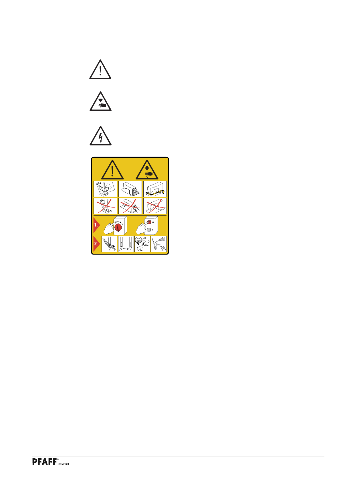
1.03 Safety symbols
Hazard point!
Special points of attention.
Risk of injury to operating personnel or technical staff!
Electric voltage!
Danger to operating personnel or technical staff
Caution!
Do not operate without finger guard and safety covers!
Turn off the main switch before threading, changing the
bobbin or needle, cleaning, etc.!
1.04 Special points of attention for the owner-operator
O This instruction manual is a part of the machine and must be made available to the
operating personnel at all times. The instruction manual must have been read before the
initial start-up.
O The operating personnel and technical staff must be instructed about the machine's
safety covers and about safe working methods.
O The owner-operator may only operate the machine in a flawless condition.
O The owner-operator must ensure that no safety covers are removed or disabled.
O The owner-operator must ensure that only authorised persons work on the machine.
Additional information can be requested from the responsible sales centre.
7
Page 8

Safety
1.05 Operating personnel and technical staff
1
.05.01 Operating personnel
Operating personnel are persons responsible for equipping, operating and cleaning the
machine and for fault clearance in the sewing area.
The operating personnel are obligated to comply with the following points:
O The safety instructions provided in the instruction manual must be followed for all work!
O Any work method jeopardising machine safety must be refrained from!
O Tight-fitting clothing must be worn. The wearing of jewellery such as chains and rings is
prohibited!
O Care must be taken to ensure that no unauthorised persons are located in the machine's
hazard zone!
O Any changes occurring on the machine which impair its safety must be reported to the
owner-operator immediately!
1.05.02 Technical staff
Technical staff are persons with technical training in electricity/electronics and mechanics.
They are responsible for lubricating, servicing, repairing and adjusting the machine.
The technical staff are obligated to comply with the following points:
O The safety instructions provided in the instruction manual must be followed for all work!
O Turn off the main switch and secure it against reactivation before starting any adjustment
and repair work!
O Never work on live parts and equipment!
Exceptions are regulated by the EN 50110 standards.
O Reattach the safety covers following repair and maintenance work!
8
Page 9

Safety
1.06 Danger warnings
A work area of 1 m must be kept free in front of and behind the machine to
ensure unobstructed access at all times.
Do not reach into the needle range during the sewing operation!
Risk of injury from the needle!
Do not allow any objects to be placed on the table during the adjustment work!
The objects could become jammed or be slung away!
Risk of injury from parts flying around!
1
4
2
3
Fig. 1 - 01
Do not operate the machine without the take-up lever guard 1!
Risk of injury due to the motion of the take-up lever!
Do not operate the machine without the cover 2!
Risk of injury due to moving parts!
Do not operate machines with an integrated motor without the start inhibitor 3!
Risk of injury due to accidental machine start-up!
Do not operate the machine without the support 4! Risk of damage due to the
top-heavy sewing head!
Machine can tip over backwards when moving it!
9
Page 10

Proper Use
2 Proper Use
The PFAFF 3511-3/01 is a high-performance, single-needle high-speed seamer for run-
stitching small parts.
The machines are used for sewing lockstitch seams in the clothing industry.
Any usage not approved by the manufacturer is deemed misuse!
The manufacturer shall assume no liability for damage caused by misuse!
Proper use also includes compliance with the operating, maintenance,
adjustment and repair measures specified by the manufacturer!
10
Page 11

Technical Data
3 Technical Data s
3
.01 PFAFF 3511-3/01
Stitch type: ......................................................................................................... 301 (lockstitch)
Needle system: ...............................................................................................................134 KK
Design B: ......................................................... for the machining of medium-weight materials
Trimming margin (depending on the design): ..................................................... 3.5 or 5.0 mm
Needle size in 1/100 mm .............................................................................................. 90 - 110
Thread thickness max.: ........................................................................................................ 120
Stitch length max: ..........................................................................................................3.5 mm
Needle bar stroke: ..........................................................................................................30 mm
Speed max.: ................................................................................................ 3000 stitches/min l
Clearance beneath the sewing foot: ............................................................................4 - 6 mm
Passage width: .............................................................................................................300 mm
Clearance height: ..........................................................................................................125 mm
Bed plate dimensions: ............................................................................................... 516 x 177
Dimensions: of the sewing head with table top
Length: ...........................................................................................................approx. 1250 mm
Width: ..............................................................................................................approx. 800 mm
Height (above table): ........................................................................................ approx. 300 mm
Ambient temperature
85% rel. humidity (condensation not permitted) ......................................................... 5 - 40 °C
Connection data:
Operating voltage: ................................................................................ 230 V ± 10%, 50/60 Hz
Max. input power: ...........................................................................................................400 VA
Fuse protection: ...................................................................................................1 x 16 A, inert
Leakage current: .......................................................................................................... < 5 mA
Working air pressure .......................................................................................................... 6 bar
Air consumption .......................................................................................... 15 l / working cycle
Noise data:
Emissions sound pressure level in the workplace at n = 2700 min-1: .............. LpA = 78 dB(A)
(Noise measurement in accordance with DIN 45 635-48-A-1,ISO 11204, ISO 3744,
ISO 4871)
u
n
Net weight of sewing head with stand: ............................................................. approx. 107 kg
Gross weight of sewing head with stand: ......................................................... approx. 147 kg
s
Subject to alterations
l
Depending on the material, workstep and stitch length
u
Due to the use of network filters there is a nominal leakage current of < 5 mA.
n
KpA = 2,5 dB
11
Page 12

Disposal of the Machine
4 Disposal of the Machine
O It is up to the customer to dispose of the machine properly.
O The materials used for the machine include steel, aluminium, brass and various plastics.
The electrical equipment consists of plastics and copper.
O The machine must be disposed of in accordance with the locally valid environmental
protection regulations, with a specialised company being contracted if necessary.
Please ensure that parts coated with lubricants are disposed of separately in
accordance with the locally valid environmental protection regulations!
12
Page 13

Transport, Packaging and Storage
5 Transport, Packaging and Storage
5.01 Transport to the customer's premises
All machines are completely packed for delivery.
5.02 Transport within the customer's premises
The manufacturer assumes no liability for transport within the customer's premises or to the
individual usage sites. Please ensure that the machines are only transported in a vertical po-
sition.
5.03 Disposal of the packaging materials
The packaging materials of these machines consists of paper, cardboard and VCI fleece. It is
up to the customer to dispose of the packaging properly.
5.04 Storage
The machine can be stored for up to 6 months when not in use. It must then be protected
from dirt and moisture. For longer storage periods, the machine's single components, espe-
cially its sliding surfaces, must be protected against corrosion, e.g. by an oil film.
13
Page 14
Work Symbols
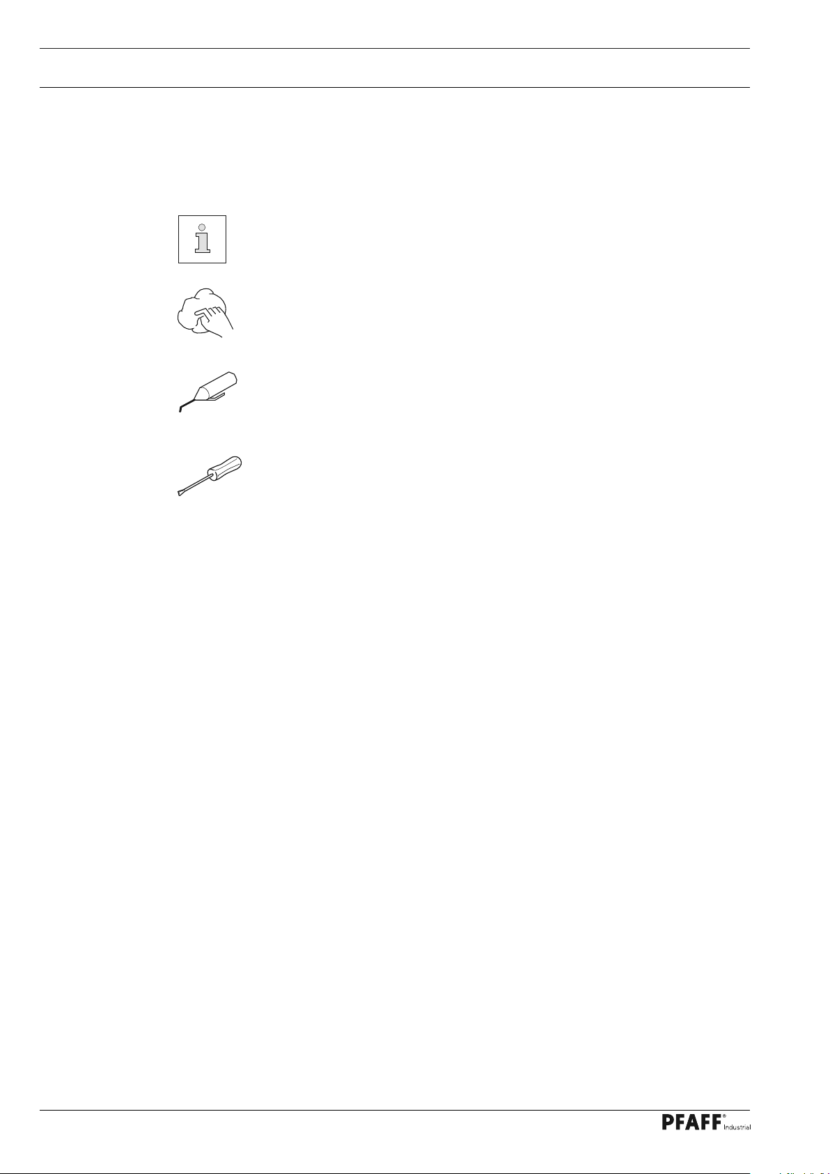
6 Work Symbols
Activities to be performed or important information in this instruction manual are
emphasised by symbols. The symbols used have the following meaning:
Note, information
Cleaning, care
Lubrication
Maintenance, repairs, adjustment, service work
(only to be carried out by technical staff)
14
Page 15
Operating Controls
7 Operating Controls
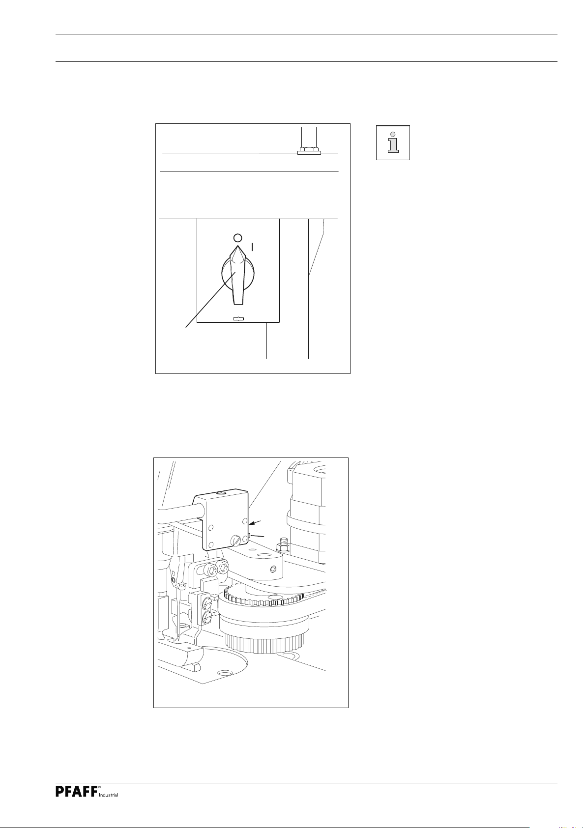
7.01 Main switch
Before switching on the ma-
chine, raise the take-up lever as
far as possible.
O Turning the main switch 1 switches the
machine on and off.
1
Fig. 7 - 01
7.02 Light barrier
O The LED 1 in the light barrier indicates
the following status:
- LED lights up green = reception
1
2
indicator.
- LED flashes green = setting aid / soiling
indicator
- LED lights up yellow = output indicator
O The key 2 on the light barrier is used to
adjust the light barrier, see chapter 14.11
Setting the light barrier in the adjust-
ment manual.
Fig. 7 - 02
15
Page 16
Operating Controls
7.03 Pedal
O With the main switch turned on.
The functions of the pedal depend
0
on the selected operating mode, see
chapter 10 Sewing.
+1
O In manual sewing:
0 = Neutral position
+1 = Sewing
- 1 = Raise sewing foot
- 2 = Trim thread
O In programmed sewing:
0 = Neutral position
+1 = Start sewing cycle
-1
Fig. 7 - 03
-2
7.04 Hand lever to raise the sewing foot
- 1 = No function
- 2 = Seam stop
O Turning the hand lever 1 raises the
sewing foot.
16
1
Fig. 7 - 04
Page 17
Operating Controls
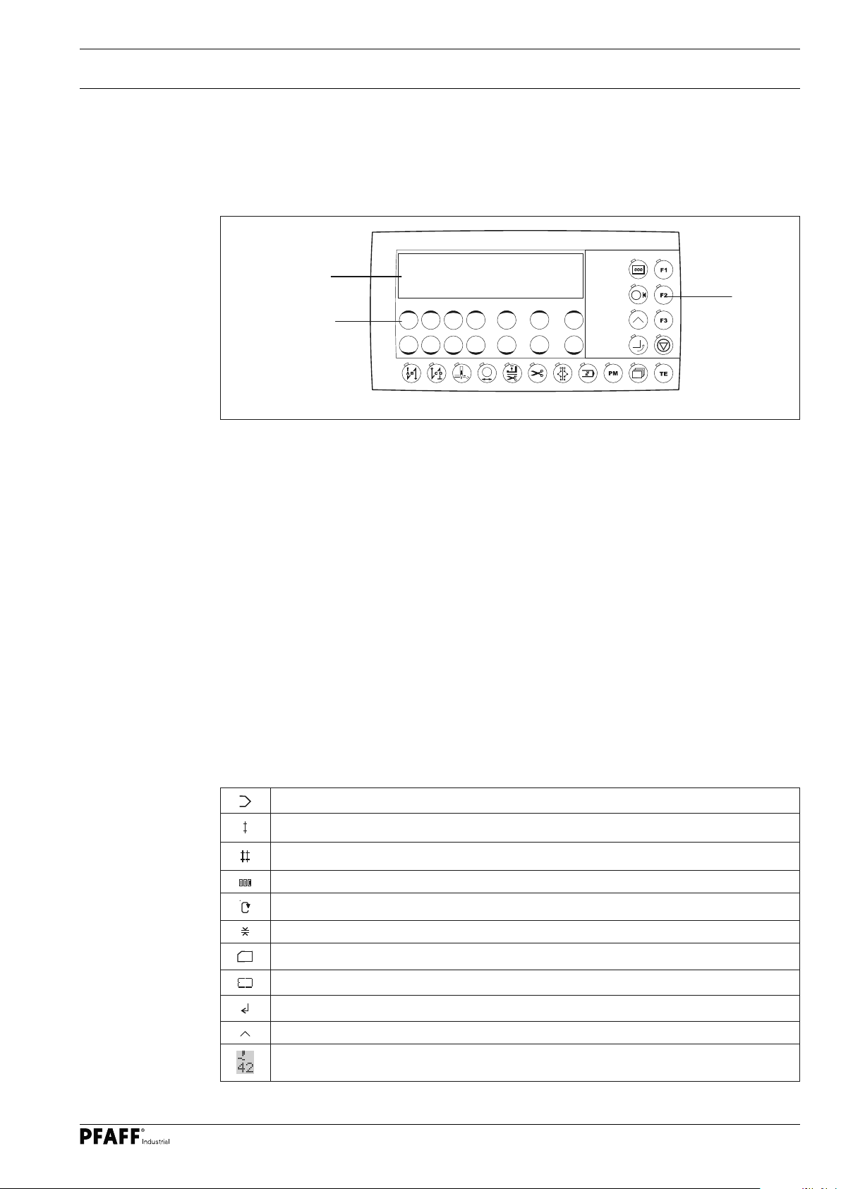
7.05 Control panel
The control panel is used to display and access machine functions for set-up and sewing, to
enter parameter values and to read error messages and service settings.
1
3
2
Fig. 7 - 05
The control panel has the following operating and display controls:
O The display 1 comprises a two-line alphanumeric LCD display with 16 characters per line
and is used to display the corresponding information and selection parameters.
O The plus/minus keys 2 are used for selecting or altering the functions and parameters
shown on the display.
O The function keys 3 are used for turning the corresponding function on and off.
Switched-on functions are each indicated by the lit LED.
7.05.01 Plus/minus keys
In addition to clear texts and set values, the following symbols appear on the display. The
symbols exclusively appear in programmed sewing, see chapter 10.02 Programmed
sewing.
Current program number
Current seam zone
Number of seam zones
Number of stitches in the current seam zone
Maximum speed in the current seam zone
Current stitch length
SD memory card
Machine memory
Enter
Program with corners
Delay stitches
17
Page 18
Operating Controls
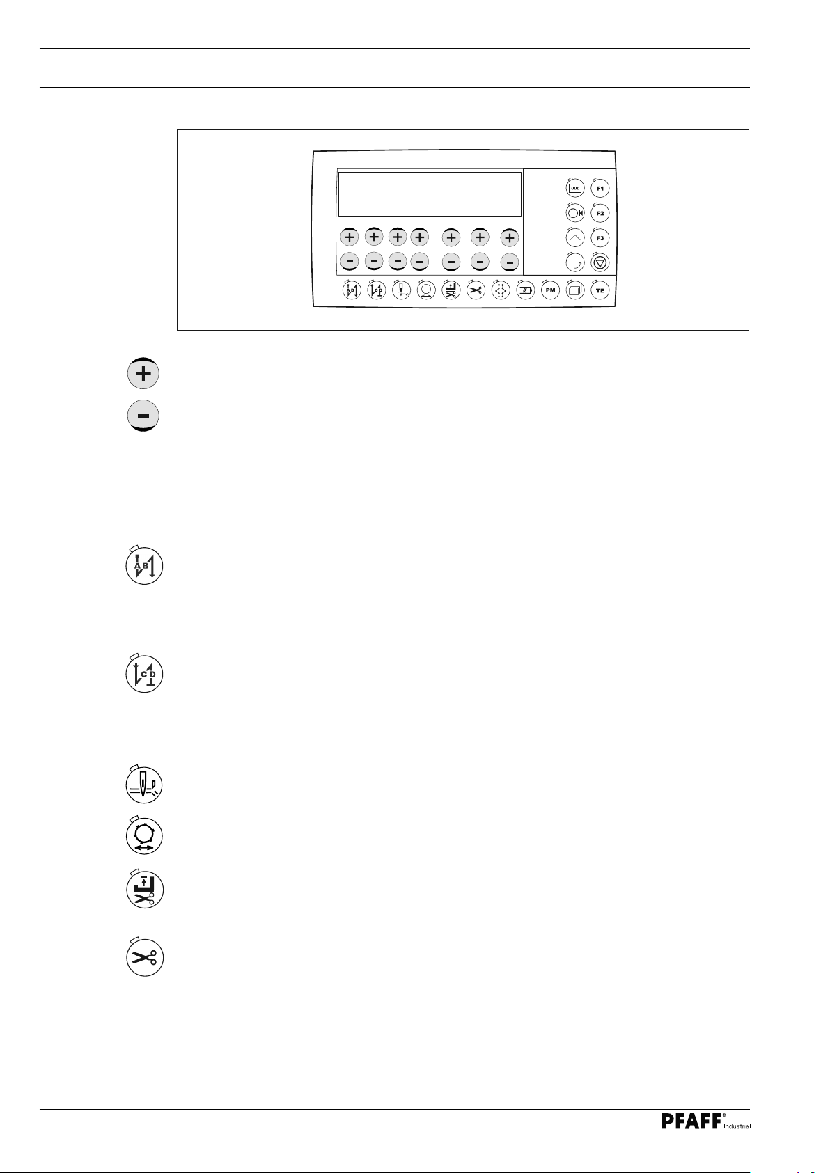
7.05.02 Plus/minus keys
Fig. 7 - 06
The selection and changing of setting values (e.g. entering the backtack stitches) can be
carried out using the corresponding +/- keys. At the same time the set value shown above is
changed slowly at first by pressing and holding the corresponding plus or minus key. If the
key is held pressed for longer, the set value changes more quickly.
7.05.03 Plus/minus keys
A
B
C D
3
3
3 3
If a function is on, this is always indicated by the correspondingly lit LED.
Detailed explanation of functions:
Start backtack
O The seam lock at seam start (start backtack) is turned on or off by pressing this key.
The number of forward stitches (A) or reverse stitches (B) of the start backtack can be
changed respectively by pressing the +/- key underneath. To convert from double back-
tack to single backtack, reset the number of stitches (A).
End backtack
O The seam lock at seam end (end backtack) is turned on or off by pressing this key. The
number of reverse stitches (C) or forward stitches (D) can be changed respectively by
pressing the +/- key underneath. To convert from double backtack to single backtack,
reset the number of forward stitches (D).
Edge trimming
O The "Edge trimming" function is switched on or off by pressing this key.
Template drive
O The "Template drive" function is switched on or off by pressing this key.
Foot position after thread trimming
O The "Foot position up after thread trimming" function is turned on or off by pressing this
key. If this function is on, the sewing foot is raised after the thread has been trimmed.
18
Thread trimming
O The "Thread trimming" function is switched on and off using this key.
Page 19

Operating Controls
Alternating sewing
O Pressing this key will switch between the linked programs.
Stitching / correcting seam programs
O The "Stitch / correct seam programs" function is switched on by pressing this key. The in-
dividual seam sections of a program can be stitched one after the other and corrected if
necessary by pressing the pedal.
PM / mode
O If this key is pressed, the programmed sewing function is switched on or off.
The program-specific parameters are shown in the alphanumeric part of the display.
Scroll
O If this key is pressed, the input menus on the display are scrolled through.
TE
O If this key is pressed, the machine changes from sewing mode to the parameter entry
function.
O The "teach-in" mode is called up by pressing this key in the seam construction diagram
function.
O The changed values are saved and sewing mode is called up by pressing this key from
the parameter entry function.
O Program management is called up by pressing this key twice, see chapter 11.01 Pro-
gram management.
Piece counter
O The piece counter is switched on or off by pressing the key. The actual value is shown
on the display when the function is switched on
Support reel
O The support reel function for the corresponding seam zone of the seam construction
diagram is switched on or off by pressing the key in the seam programming function.
The support reel in the corresponding seam zone extends in programmed sewing with
the seam construction diagram.
Corner programming
O The corresponding function is switched on or off by pressing the key. The corner pro-
gramming for the corresponding seam zone of the seam construction diagram is per-
formed when the function is switched on.
Turning corners
O The corresponding function is switched on or off by pressing the key. The "Turn corners"
function for the current seam zone is performed according to the distance indicated on
the display when the function is switched on.
F1 (cycle time)
O The cycle time display (duration of a seam sequence) is switched on or off on the display
by pressing the key.
19
Page 20

Operating Controls
F2 (setting aid for the edge trimmer)
O The corresponding function is switched on or off by pressing the key.
The edge knife moves to the trimming position in manual sewing when the function is
switched on.
F3
O After calling up the corresponding "PC" (piece counter) function, the piece counter is
reset by pressing this key, see chapter 10.03.03 Switching on the edge trimmer with a
time delay (waistband extension)
Start inhibitor
O The start inhibitor is switched on or off by pressing the key. The sewing or seam
sequence cannot be started when the function is switched on.
20
Page 21
Set-up and Initial Commissioning
8 Set-up and Initial Commissioning
The machine may only be set up and started up by qualified personnel! All of
the relevant safety regulations must always be complied with in this process!
If the machine was delivered without a table, then the stand and the table top
provided must safely support the weight of the machine and its motor.
Adequate stability of the stand must be guaranteed, even during the sewing
operations.
8.01 Set-up
Suitable electrical supply connections must be provided at the erection site, see chapter 3
Technical Data. The erection site must also have a firm and level subsurface and adequate
lighting.
The table top is lowered for packaging purposes.
The adjustment of the table height is described below.
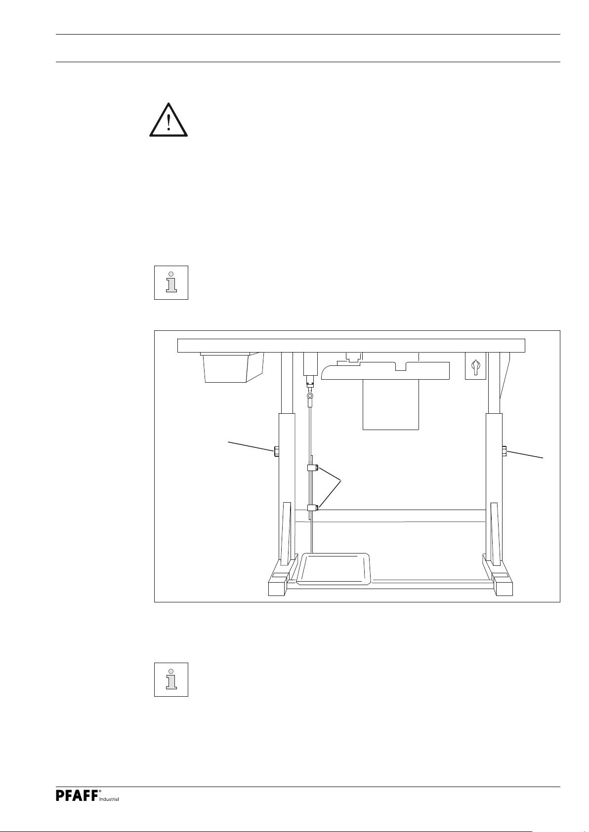
8.01.01 Setting the table height
1
2
Fig. 8 - 01
O Loosen the screws 1 and 2.
O Move the table top to the desired working height by pulling it out and pushing it in and
align the table top horizontally.
Adjust the stand on both sides evenly to prevent it tilting.
O The stand must have all four feet firmly on the ground to make sure it is positioned
securely.
1
O Firmly tighten the screws 1.
O Adjust and tighten the desired pedal position on the screws 2.
21
Page 22

Set-up and Initial Commissioning
8.01.02 Inserting the sewing machine into the stand
1
1
2
Fig. 8 - 02
O The hinge 1 is screwed to the sewing head base plate.
O Insert the sewing machine into the table top.
O Insert the sewing head support 2 into the table top hole.
Do not operate the machine without the support 2! Risk of damage due to the
top-heavy sewing head!
Machine can tip over backwards when moving it!
22
Page 23

8.01.03 Assembling the start inhibitor
2
1
Set-up and Initial Commissioning
Fig. 8 - 03
O Insert the machine into the table top, see chapter 8.01.02 Inserting the sewing
machine into the stand
O After loosening the screws 2, adjust the switch 1 in such a way that the switch 1 is
actuated when the sewing head is mounted.
O Tighten the screws 2 in this position.
23
Page 24

Set-up and Initial Commissioning
8.02 Connecting the plug-in connections and ground cable
B
X4/A
X4
E
X7
X2
X3
X5
X1
X6
0
1
3
X0
4
D
C
D
B
A
X23
2
Fig. 8 - 04
O Insert all plugs on the control box 2 in accordance with their designation.
O Insert the "motor" into the bushing X 1 and the bushing X 2.
Attention
Plugging in the connector incorrectly can damage the control unit!
O Attach the following ground cables in order to discharge static electricity.
O Securely attach the ground cable from the sewing head 1 to ground point A.
O Securely attach the ground cable from the control point B to ground point B.
O Securely attach the ground cable from the main switch 3 to ground point C.
O Securely attach the ground cable from the stand 4 to ground point D
O Securely attach the ground cable from the motor cable X1 to ground point E
24
Page 25

8.03 Assembling the reel stand
Set-up and Initial Commissioning
O Assemble the reel stand as shown in the
adjacent illustration.
O Then insert the stand into the
O hole in the table top and secure it with
the enclosed nuts.
Fig. 8 - 05
25
Page 26

Set-up and Initial Commissioning
8.04 Initial start-up
1
3
8
6
4
50
2
0
10
100
150
12
200
14
230
0
16
2
Fig. 8 - 06 Fig. 8 - 07
O Inspect the machine, particularly the electric cables, for any damage.
O Remove the plug 1 of the oil reservoir 2 before the initial commissioning.
The plug 1 serves solely for transit support and may not be used during the
sewing operations.
O Clean the machine thoroughly and then oil it, see also chapter 12 Maintenance and
Care.
O Connect the machine to the compressed air system. The manometer 3 must show a
pressure of 6 bar. Set this value if required, see chapter 12.04 Checking / setting the air
pressure.
O Arrange for technical staff to check whether the machine's motor may be operated at the
existing mains voltage and whether it is connected properly.
Never operate the machine if there are any differences.
The machine must only be connected to a grounded socket!
26
O With the machine running, the handwheel must turn towards the operator, otherwise
arrange for technical staff to adjust the motor, see chapter 11.02 Parameter settings.
Page 27

Set-up and Initial Commissioning
8.05 Switching the machine on / off
O Switch the machine on (see chapter 7.01 Main switch).
8.06 Checking the start inhibitor function
Error
E009
PRESS TE
O Switch on the machine at the main switch and move the sewing head.
The error message "E009" must appear on the control panel.
O If the message does not appear, check the start inhibitor setting as explained in chapter
8.01.03 Assembling the start inhibitor.
O Return the sewing head to its upright position and acknowledge the error message by
pressing the TE/Speed key. The machine is ready for operation again.
8.04 Machine drive home position
O Activate service level "c", see chapter 11.02.01 Selecting the user level.
798c *1
O Call up parameter "700" by pressing the +/- keys (P) or (S).
700c 0
O Make a stitch using the pedal function.
O Turn the handwheel in the direction of rotation until the lower edge of the needle eye is
on the upper edge of the needle plate, approaching from above.
O Complete the adjustment of the sewing motor by pressing the "TE" key.
27
Page 28

Set-up
9 Set-up
9.01 Inserting the needle
Observe and comply with all regulations and instructions in this instruction
manual.
Pay particular attention to all safety regulations!
All set-up work may only be carried out by appropriately instructed personnel.
Disconnect the machine from the electricity mains for all set-up work by operat-
ing the main switch or by removing the mains plug!
Switch off the machine!
Risk of injury due to accidental
machine start-up!
Only use needles of the system
intended for the machine, see
chapter 3 Technical Data!
Fig. 9 - 01
1
O Bring the needle bar to the top position.
2
O Loosen the screw 1 and insert the
needle 2 until you feel it stop. The long
groove must point to the left.
O Tighten the screw 1
28
Page 29

Set-up
9.02 Winding the bobbin thread, adjusting the thread tension
7
4
1
6
5
3
9
2
8
Fig. 9 -02
O Fit the empty bobbin 1 onto the bobbin winder spindle 2 with the rest thread chamber on
the outside.
O Thread in the thread as shown in Fig. 9 - 02 and wind it round the bobbin 1 a few times in
an anti-clockwise direction.
O Switch on the bobbin winder by pressing the bobbin winder spindle 2 and the lever 3
simultaneously.
The bobbin fills up during sewing.
If the machine is only run for bobbin winding (without sewing), a bobbin case
must be fitted in the hook.
Otherwise a jammed thread may damage the hook!
O The tension of the thread on the bobbin 1 can be adjusted with the knurled thumb screw 4.
O The bobbin winder stops automatically when the bobbin 1 is sufficiently full.
O Remove the filled bobbin 1 and cut the thread with the blade 5.
O The fill amount of the bobbin 1 can be adjusted with the pin 8 (loosen the screw 9 and
tighten it again)
If the thread is wound unevenly:
O Loosen the nut 6.
O Turn the thread guide 7 accordingly.
O Tighten the nut 6.
29
Page 30

Set-up
9.03 Removing / inserting the bobbin case
Switch off the machine!
Risk of injury due to accidental
machine start-up!
1
2
Fig. 9 -03
Removing the bobbin case:
O Tilt machine backwards.
O Raise the lever 1 and remove the bobbin
case 2.
Inserting the bobbin case:
O Press the bobbin case 2 until you feel it
snap into the bobbin case base.
Return the machine to its up-
right position using both hands!
Danger of injury by crushing be-
tween the machine and the ta-
ble top
9.04 Inserting the bobbin case / adjusting the bobbin thread tension
2
1
5 cm
30
3
Fig. 9 -04
O Insert the bobbin 1 into the bobbin case 2 as shown in Fig. 9 - 04.
O Pass the thread through the slot under the spring as shown in Fig. 9 - 05.
When the thread is drawn off, the bobbin must turn in the direction shown by the
arrows.
O Adjust the thread tension by turning the screw 3.
Fig. 9 -05
Page 31

Set-up
9.05 Threading the needle thread / adjusting the needle thread tension
1
Fig. 9 - 06
+
-
Switch off the machine!
Risk of injury due to accidental machine start-up!
O Thread the needle thread as shown in Fig. 9 - 06. Please ensure that the needle is thread-
ed from the left.
O Adjust the needle thread tension by turning the adjusting wheel 1.
31
Page 32

Set-up
9.06 Entering the stitch length
O Switch the machine on.
O The current value of the stitch length is shown on the display after switching on the
machine
O Set the stitch length by pressing the corresponding +/- keys (P) or (S) .
2.5
9.07 Entering the start and end backtacks
O Switch the machine on.
2.5
O Switch on the corresponding function (LED in the key lights up) by pressing the start
backtack and/or end backtack keys.
O Switch to the input menu for the start and end backtack by pressing the scroll key.
3
3 3 3
32
Page 33

Set-up
A
B
C
D
O Select the desired value for the number of start backtack forward switches (A) by press-
ing the corresponding +/- key.
O Select the desired value for the number of start backtack reverse stitches (B) by pressing
the corresponding +/- key.
O Select the desired value for the number of end backback reverse stitches (C) by pressing
the corresponding +/- key.
O Select the desired value for the number of end backtack forward stitches (D) by pressing
the corresponding +/- key.
O The input menu for the stitch length is called up again by pressing the scroll key.
9.08 Inserting and removing the SD memory card
Insert the SD card
1
O Open the cover 1.
O Insert the SD card 2 into the card slot
with the label facing forwards.
2
2 GB
max.
O Close the cover 1 again.
Remove the memory card
O Open the cover 1.
3
Fig. 9 - 07
Adjusting the slide 3 makes it possible to activate ("LOOK" position) or deactivate
the write protection function on the SD card. The write protection function must
be deactivated to store, edit or delete data on the SD card.
O The SD card must be kept for future boot processes.
O Press gently on the corner of the SD card
2 - the SD card will be ejected.
O Close the cover 1 again.
Only use FAT 16 format
memory cards.
O The SD card is not a default configuration.
33
Page 34

Set-up
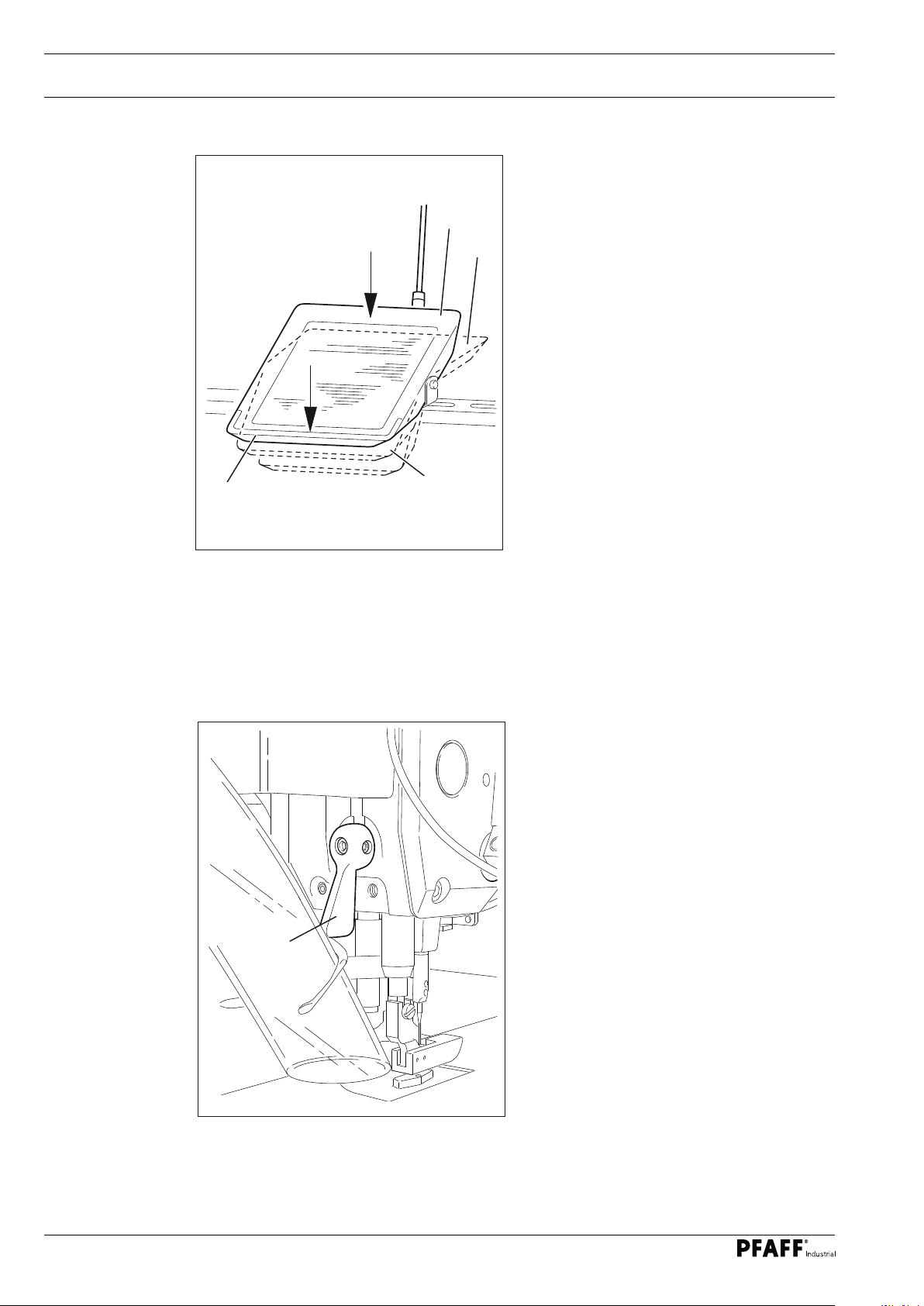
9.09 Inserting the workpiece
9
.09.01 Loading the sewing template
4
2
3
3
34
Fig. 9 - 08
O Insert the lining between the supporting surface 1 and the material clamp 2 until it
touches the guide pins 3.
O Close the material clamp 2.
O Place a rough cut for the fullness on the material clamp 2 and close the material clamp 4.
1
Page 35

Set-up
9.09.02 Inserting the sewing template
1
Fig. 9 - 09
O Feed the sewing template 1 into the guide on the needle plate and slide it through until
you feel it stop. The machine is ready to start.
35
Page 36

Sewing
10 Sewing
10.01 Manual sewing
In sewing mode all settings relevant for the sewing operation are shown in the display.
Functions can be turned on or off by pressing the keys; values for the most important pa-
rameters can be changed directly.
A difference is made between manual sewing and programmed sewing in this mode.
A change is made from manual to programmed sewing by pressing the PM key. The program numbers 1 - 99 can each be assigned with a seam program with up to 15 seam zones.
Manual sewing is used for setting up and testing. It is not normally used for production.
After the machine has been switched on and manual sewing has been selected by pressing
the PM key, the display appears for entering the stitch length, see also chapter 9.06 Setting
the stitch length.
If the backtack function is switched on, the display appears for entering the backtack values,
see also chapter 9.07 Entering the start and end backtacks.
Pressing the scroll key switches between the displays.
3
3 3 3
2.5
36
The TE key can be used to choose between the following menus in manual sewing:
- Number of backtack stitches and stitch length
- Parameters
- SD card
Page 37

Sewing
Select menu, see also chapter 9.06 Entering the stitch length.and 9.07 Entering the start
and end backtacks.
3
3 3 3
Select menu, see also chapter 11.02.02 Example of a parameter entry
660a 0
2.5
Select menu, see also chapter 11.01.04 Copying single programs and machine data onto
the SD memory card
COPY
For other functions during manual sewing, see also chapter 7.05.03 Function keys:
Start backtack on/off Line selection*
End backtack on/off Parameter entry / program management
Edge trimmer on/off Display the piece counter on/off
Template drive on/off Support reel on/off
Raise sewing foot after
thread trimming on/off
Edge knife setting aid on/off
Thread trimming on/off Start inhibitor on/off
* The function is available from mechanic level "b", see chapter 11.02.01 Selecting the
user level.
O Insert the workpiece if required, see chapter 9.09 Inserting the workpiece.
O Sewing is performed using the pedal function, see also chapter 7.03 Pedal.
37
Page 38

Sewing
10.02 Programmed sewing
A seam construction diagram must first be created and saved in the machine
memory for programmed sewing, see chapter 10.03 Creating/changing seam
construction diagrams or chapter 11.01 Program management.
O Switch on the machine, see chapter 8.05 Switching the machine on/off.
O Call up manual sewing if required. (The LED in the key must light up).
1
The scroll key can be used to choose between the following menus in programmed sewing:
- Program-related values
- Seam section-related values
- Bartack and edge trimmer delay
1 15
0
Program-related values menu
Functions in programmed sewing, see also chapter 7.05.03 Function keys.
1
Seam section-related values menu
Functions in programmed sewing, see also chapter 7.05.03 Function keys.
1
In the seam section-related values menu, with the corner function switched on .
1 15
1500 2.5
0
32
38
1
15 2.5
3225
Page 39

Sewing
In the seam section-related values menu, the "Seam end by light barrier" function is activated with F2 and in this way the stitch count serves as light barrier compensation stitches.
- - -
3
Additional functions:
Display the stitch counter in the seam section-related values menu.
500 4.5
10
PC: 16
1
500 4.5
50
The stitch counter can be reset after selecting the corresponding function by
pressing the "F3" key.
Display the cycle time in the seam section-related values menu.
T: 11.3s
1
500 4.5
Bartack and edge trimmer delay menu
Functions in programmed sewing, see also chapter 7.05.03 Function keys.
A
B C D
3
3 3 3
50
O Change the number of stitches for the waistband extension by pressing the +/- key (S).
39
Page 40

Sewing
Functions in programmed sewing, see also chapter 7.05.03 Function keys:
Start backtack on/off Change seam construction diagram*
End backtack on/off Line selection*
Edge trimmer on/off Display the piece counter on/off
Template drive on/off Support reel on/off
Raise sewing foot after
thread trimming on/off
Thread trimming on/off Display the cycle time on/off
Alternating sewing Start inhibitor on/off
* The function is available from mechanic level "b", see chapter 11.02.01 Selecting the
user level.
O Insert the workpiece, see chapter 9.09 Inserting the workpiece.
O Select the program number of the desired seam construction diagram by pressing the
+/- keys (P).
O Start the seam sequence by pressing the pedal, see chapter 7.03 Pedal.
10.03 Entering the authorisation code
Some keys are locked for operators. A double beep sounds when these keys are pressed.
An authorisation code needs to be entered and confirmed with "Enter" to obtain authorisation. Authorisation is automatically granted if logged on as a mechanic.
Corner programming*
40
CODE: 3511
O Press the "Enter code" key
O Enter the desired authorisation code (e.g. 3511) by pressing the +/- key (A;B;C and D).
O Finish the input by pressing the "Enter" key +/- key (L)
Page 41

Sewing
10.04 Creating / changing seam construction diagrams
10
.04.01 Creating a seam construction diagram in "teach-in mode"
The "teach-in" function is particularly suitable for creating completely new seam construc-
tion diagrams. The seam construction diagram is saved directly in the machine memory by
stitching the seam zones. The creation of a seam construction diagram is explained below
by means of an example.
Seam zone 5
Stitches: 35
Stitch length: 2.2 mm
Speed: 2200 min
Turn: 23 mm
-1
Seam zone 4
Theoretical stitch length: 1.2 mm
Actual stitch length: 8.0 mm
Stitches: 5
Speed: 1500 min
-1
Seam zone 3
Stitches: 66
Stitch length: 2.2 mm
Speed: 2200 min
-1
Seam zone 1
Stitches: 32
Stitch length: 2.2 mm
Speed: 2200 min
Turn: 23 mm
Seam zone 2
Stitches: 7
Stitch length: 2.2 mm
Speed: 2200 min
Turn: 10 mm
O Switch the machine on.
O Activate mechanic level "b", see chapter 11.02.01 Selecting the user level or enter the
authorisation code, see chapter 10.03 Entering the authorisation code.
10
1 5
0
-1
-1
O Switch on programmed sewing if required (LED in the key lights up).
O Select the desired program number (e.g. 10) by pressing the +/- key (A).
O Limit the number of seam zones (e.g. 5) by pressing the +/- key (P).
O Select the program linkage (0 = none) by pressing the +/- key (L).
O Select the seam section menu by pressing the scroll key
1
2200 2.2
32
O Select the desired value for the stitch length (e.g. 2.2 mm) by pressing the +/- keys (P; S).
O Select the desired speed (e.g. 2200) by pressing the +/- key (B; C)
41
Page 42

Sewing
O Call up "teach-in mode". (The LED in the key flashes.)
O Insert the workpiece, see chapter 9.09 Inserting the workpiece.
O Stitch the first seam zone to the first corner using the pedal function (e.g. 32 stitches).
O Call up corner programming. (LED in the key lights up.)
1
22 2.2
O Select the desired turn (e.g. 23 mm) by pressing the +/- keys (D).
O Switch on the "Turn corner" function for the seam zone. The turn is performed
(The turning range can be corrected by pressing the +/- keys (S)).
3223
O Select the second seam zone by pressing the +/- keys (A).
2
2200 2.2 7
O Select the desired speed (e.g. 2200) by pressing the +/- key (B; C)
O Select the desired value for the stitch length (e.g. 2.2 mm) by pressing the +/- keys
(P; S).
O Stitch the second seam zone using the pedal functions (e.g. 7 stitches).
O Call up corner programming. (LED in the key lights up.)
42
2
22 2.2
710
Page 43

Sewing
O Select the desired turn (e.g. 10 mm) by pressing the +/- keys (D).
O Switch on the "Turn corner" function for the seam zone. The turn is performed.
O Select the third seam zone by pressing the +/- keys (A).
3
2200 2.2 66
O Select the desired speed (e.g. 2200) by pressing the +/- key (B; C)
O Select the desired value for the stitch length (e.g. 2.2 mm) by pressing the +/- keys (P; S).
O Stitch the third seam zone using the pedal functions (e.g. 66 stitches).
O Select the fourth seam zone by pressing the +/- keys (A).
4
1500 8.0 5
O Select the desired speed (e.g. 1500) by pressing the +/- key (B; C).
O Change the value for the stitch length (e.g. 8 mm) by pressing the +/- keys (P; S).
O Stitch the fourth seam zone using the pedal functions (e.g. 5 stitches).
O Select the fifth seam zone by pressing the +/- keys (A).
5
2200 2.2 35
43
Page 44

Sewing
O Select the desired speed (e.g. 2200) by pressing the +/- key (B; C).
O Change the value for the stitch length (e.g. 2.2 mm) by pressing the +/- keys (P; S).
O Stitch the fifth seam zone using the pedal functions (e.g. 35 stitches).
O Call up corner programming. (LED in the key lights up.)
5
22 2.2
O Select the desired turn (e.g. 23 mm) by pressing the +/- keys (D).
O Switch on the "Turn corner" function for the seam zone. The turn is performed.
3523
O Exit "teach-in mode". (The LED in the key does not light up.)
The machine initiates thread trimming and saves the program.
O Carry out a test seam and make corrections to the seam construction diagram if neces-
sary, see chapter 10.04.02 Changing seam construction diagrams.
Functions, such as "start backtack/end backtack", "edge trimmer", "thread trim-
mer" etc. can be assigned to the corresponding seam construction diagram by
activating the respective key.
44
Page 45

Sewing
10.04.02 Changing seam construction diagrams
If a seam construction diagram has been created in "teach-in mode", minor corrections are
usually needed that can be made as described below.
O Switch the machine on.
O Activate mechanic level "b", see chapter 12.12.01 Selecting the user level or enter the
authorisation code, see chapter 10.03 Entering the authorisation code.
10
O Select the program number of the seam construction diagram to be changed (e.g. 10) by
pressing the +/- key (A).
1 5
0
O Change the global function, such as start and end backtack if required, see chapter 9.07
Entering the start and end backtacks.
O Select the seam section menu by pressing the scroll key
1
22 2.2
O Select the seam zone of the seam construction diagram to be changed (e.g. 2) by press-
ing the +/- key (A).
2
22 2.2
3223
710
2x
O Values can be changed directly with the keys below.
O Press the PM key twice to finish
As any change has an effect on subsequent seam zones, these seam zones
must also be corrected!
45
Page 46

Sewing
ERROR 9
10.05 Error messages
When a fault occurs, the display shows "ERROR" together with an error code, as shown
in the following example. In addition, the LED in the memory card slot lights up red (see
arrow). An error message can be caused by the incorrect set up, faulty elements or
overloading.
O Correct the fault.
O Confirm the error correction if required by pressing the TE key.
The LED in the memory card slot lights up yellow (see arrow).
For a description of errors see chapter 11.07 Error codes and descriptions.
46
Page 47

Input
11 Input
11.01 Program management
The program numbers which are saved in the machine memory or on the SD card are
displayed in program management. The programs can be deleted or copied. Conventional
SD memory cards up to a maximum of 2GB can be inserted into the control panel. The
machine data is saved in the file "MD" in the subdirectory \P3511. The programs are saved in
the directory \P3511 in the files 01 – 99.
The insertion and removal of the SD memory card is described in chapter 9.08 Inserting
and removing the SD memory card.
If SD memory cards are to be formatted using a PC, they must be formatted in "FAT16" format. Alternatively, the SD memory card can also be formatted using the formatting function
on the corresponding machine, see chapter 11.01.10
Formatting the SD memory card.
11.01.01 Calling up program management
O Switch the machine on.
O Call up manual sewing if required. (The LED in the key does not light up.)
2x
O Press the TE key twice
O Program management is called up by pressing the scroll key.
DIR
After calling up program management, the first menu item appears (display of the program
in the machine memory).
Confirm selection of the menu item by pressing the right plus key.
Further menu items can be scrolled through by pressing the left +/- keys, see the following
chapter.
The following menu items are available in program management:
O Display of the program in the machine memory
O Display of the program and the machine data on the inserted SD memory card
O Copying of single programs and the machine data onto the SD memory card
O Copying of all programs and the machine data onto the SD memory card
O Copying of single programs and the machine data in the machine memory
O Copying of all programs and the machine data in the machine memory
O Deleting programs in the machine memory
O Deleting programs and machine data on the SD memory card
O Formatting the SD memory card
47
Page 48

Input
11.01.02 Displaying programs in the machine memory
O To call up program management, see chapter 11.01.01 Calling up program
management.
DIR
O Press the left +/- keys until the corresponding menu item is displayed.
O Confirm selection of the menu item by pressing the right plus key.
DIR
1 2 40 42 END
O The machine memory can be scrolled through within the display by pressing "+" on the
right +/- keys.
O The programs (1 - 99) are displayed. Only occupied program places are displayed.
O Further menu items of program management are called up by pressing the left +/- keys.
48
Page 49

Input
11.01.03 Displaying programs and the machine data on the SD memory card
O To call up program management, see chapter 11.01.01 Calling up program
management.
DIR
O Press the left +/- keys until the corresponding menu item is displayed.
O Confirm selection of the menu item by pressing the right plus key.
DIR
1 2 40 42 END
O The SD memory card can be scrolled through within the display by pressing "+" on the
right +/- keys.
O Programs (1 - 99) and machine data (MD) are displayed. Only occupied program places
and saved machine data are displayed.
O Further menu items of program management are called up by pressing the left +/- keys.
49
Page 50

Input
11.01.04 Coping programs and machine data onto the SD memory card
O To call up program management, see chapter 11.01.01 Calling up program
management.
COPY
O Press the left +/- keys until the corresponding menu item is displayed.
O Confirm selection of the menu item by pressing the right plus key.
COPY
«
2
«
1
O Select the data to be copied from the machine memory to the SD memory card (pro-
grams 01 - 99) by pressing the +/- keys under the symbol of the machine memory.
O When copying programs, select the program number for saving on the SD memory card
by pressing the +/- keys under the symbol of the memory card.
O Confirm the copying process by pressing the right plus key.
O Further menu items of program management are called up by pressing the left +/- keys.
If a program is already present on the SD memory card, a prompt for confir-
mation will be displayed. The program will be overwritten by pressing the right
plus key. Pressing the right minus key will cancel the operation.
50
Page 51

Input
11.01.05 Copying all programs and machine data onto the SD memory card
O To call up program management, see chapter 11.01.01 Calling up program
management.
COPY
O Press the left +/- keys until the corresponding menu item is displayed.
O Confirm selection of the menu item by pressing the right plus key.
COPY
ALL
ALL
«
«
ALL
O Confirm the copying process by pressing the right plus key.
O Further menu items of program management are called up by pressing the left +/- keys.
51
Page 52

Input
11.01.06 Copying single programs and machine data in the machine memory
O To call up program management, see chapter 11.01.01 Calling up program
management.
COPY
O Press the left +/- keys until the corresponding menu item is displayed.
O Confirm selection of the menu item by pressing the right plus key.
COPY
«
«
1
2
O Select the data to be copied from the SD memory card to the machine memory (pro-
grams 01 - 99) by pressing the +/- keys under the symbol of the memory card.
O When copying programs, select the program number for saving on the machine memory
by pressing the +/- keys under the symbol of the memory card.
O Confirm the copying process by pressing the right plus key.
O Further menu items of program management are called up by pressing the left +/- keys.
If a program is already present in the machine memory, a prompt for confir-
mation will be displayed. The program will be overwritten by pressing the right
plus key. Pressing the right minus key will cancel the operation.
52
Page 53

Input
10.01.07 Copying all programs and machine data in the machine memory
O To call up program management, see chapter 11.01.01 Calling up program
management.
COPY
O Press the left +/- keys until the corresponding menu item is displayed.
O Confirm selection of the menu item by pressing the right plus key.
COPY
ALL
«
ALL
«
ALL
O Confirm the copying process by pressing the right plus key.
O Further menu items of program management are called up by pressing the left +/- keys.
53
Page 54

Input
11.01.08 Deleting programs in the machine memory
O To call up program management, see chapter 11/01/2001 Calling up program
management.
DEL
O Press the left +/- keys until the corresponding menu item is displayed.
O Confirm selection of the menu item by pressing the right plus key.
DEL
1
O Select the data to be deleted from the machine memory (programs 01 - 99) by pressing
the +/- keys under the symbol of the machine memory.
O Confirm the deletion process by pressing the right plus key.
O Further menu items of program management are called up by pressing the left +/- keys.
Before the deletion process, a prompt for confirmation will be displayed. The
program will be overwritten by pressing the right plus key. Pressing the right
minus key will cancel the operation.
54
Page 55

Input
11.01.09 Deleting programs and machine data on the SD memory card
O To call up program management, see chapter 11.01.01 Calling up program
management.
DEL
O Press the left +/- keys until the corresponding menu item is displayed.
O Confirm selection of the menu item by pressing the right plus key.
DEL
2
O Select the programs to be deleted on the SD memory card (programs 1 - 99) by pressing
the +/- keys under the symbol of the SD memory card.
O Confirm the deletion process by pressing the right plus key.
O Further menu items of program management are called up by pressing the left +/- keys.
Before the deletion process, a prompt for confirmation will be displayed. The
program will be overwritten by pressing the right plus key. Pressing the right
minus key will cancel the operation.
55
Page 56

Input
11.01.10 Formatting the SD memory card
O To call up program management, see chapter 11.01.01 Calling up program
management.
FORMAT
O Press the left +/- keys until the corresponding menu item is displayed.
O Confirm selection of the menu item by pressing the right plus key.
Before the start of formatting, a prompt for confirmation will be displayed. The
formatting process is confirmed by pressing the right plus key. The formatting
process can be cancelled by pressing the right minus key
The card is completely formatted if it cannot be read. If it is readable and the directory \P3511x for the 3511 exists, the machine data and the subdirectories
for all programs are deleted.
If the directory \P3511 for the 3511 does not exist, the directory is created. This
is to ensure that programs from other machines and other files are not lost.
O Further menu items of program management are called up by pressing the left +/- keys.
56
Page 57

Input
11.02 Parameter settings
11.02.01 Selecting the user level
By default, the machine is in user level "a" when it is switched on. The following
section describes how to call up the service level "c" via the mechanic level "b".
Set values in the parameters of user levels "b" and "c" may only be changed by
trained technical staff!
O Switch the machine on.
O Call up manual sewing if required. (The LED in the key does not light up.)
O Call up parameter entry.
660a 0
O Call up parameter "798" by pressing the corresponding +/- keys (P) or (S) .
798a 0
O Enter the corresponding value for the desired user level by pressing the +/- keys (L):
0
= Operator level "a"
1 = Mechanic level "b"
11 = Service level "c"
O Press the TE key to complete the selection.
The operator level "a" is active again after switching the machine off and on
again. The corresponding letter "a", "b" or "c" for the current user level is shown
on the display.
57
Page 58

Input
11.02.02 Example of a parameter entry
O Switch the machine on
O Press the TE key to call up the parameter entry function.
The selection of editable parameters depends on the active user level, see chapter
11.02.01 Selecting the user level and chapter 11.02.03 List of parameters.
116a 0
O Select the desired parameter by pressing the +/- keys (P) e.g. parameter "660" (bobbin
thread monitoring).
660a 0
O Set the desired value for the parameter by pressing the +/- keys (L), e.g. value "2" (bobbin
thread monitoring using stitch counting).
660a 2
The value for the number of stitches for bobbin thread monitoring is entered via
parameter "760.
58
O The values of the changed parameters are accepted and sewing mode is called up by
pressing the TE key.
Page 59

Input
11.02.03 List of parameters
Group
Parameter
1
105 Speed for seam start B,C 300 - 1500 1000
110 Speed for seam end B,C 300 - 1500 1000
116 Soft starting stitches B,C 0 - 30 0
117 Speed for soft starting stitches B,C 30 - 1000 400
3
382 Analogue input switching threshold for the
Description
thread monitor
User level
B,C 0 - 100 15
Setting range
Set value
387 Output Ax (motor operation) is active
ON = with the pedal 1D (motor running);
OFF = with the pedal 1 (lower presser foot)
4
452 "Lock-out" input
ON = yes
OFF = no (no function)
5
521 Needle position at sewing stop before seam
end
ON = needle position "2" (top)
OFF = needle position "1" (bottom)
538 Output timing Ax (thread tension release) B,C 10 - 50 30
6
605 Actual speed on the display
ON = yes
OFF = no
606 Speed stage 1 (min.) B,C 30 - 300 180
607 Speed stage 12 (max.) B,C 300 - 3500 2500
609 Trimming speed 1 B,C 60 - 300 180
B,C ON - OFF ON
B,C ON - OFF ON
B,C ON - OFF ON
B,C ON - OFF OFF
615 End detection by light barrier
ON = from light to dark;
OFF = from dark to light
618 Reverse rotation after seam end
ON = yes
OFF = no
623 Switch-on delay for reverse rotation [ms] B,C 0 - 2000 30
B,C ON - OFF ON
B,C ON -OFF ON
59
Page 60

Input
Group
Parameter
6
651 Presser foot with automatic lowering if the
Description
machine is at a standstill
ON = yes
OFF = no
User level
B, C ON -OFF ON
Setting range
Set value
660 Bobbin thread monitoring
0 = without (= *II*)
1 = via sensor (= **I*)
2 = via stitch counting
668 Thread wiper / thread blower
ON = yes
OFF = no
7
700 Needle position "0"
needle)
702 Needle position "1" (needle down) B,C 0 - 255 80
703 Needle position "2" (thread lever up) B,C 0 - 255 226
705 Needle position "5"
(Magnetic thread trimming / end of cutting
signal "1", start of cutting signal timing "1")
706 Needle position "6"
(Pneumatic thread trimming / start of cutting
signal "2")
707 Needle position "9"
(Start of thread tension release / start of
thread catcher)
(reference position of
A,B,C 0 - 2 0
B,C ON - OFF ON
B,C 0 - 255 0
B,C 0 - 255 200
B,C 0 - 255 80
B,C 0 -255 164
60
715 Extension time for blowing and suction
after the seam end
718 Standstill brake timing
0 = brake off
719 Timing adjustment A4 (presser foot) B,C 10 - 60 40
722 Acceleration ramp
1 = flat
50 = steep
723 Braking ramp
1 = flat
50 = steep
729 Start delay after lowering the presser foot [ms] B,C 10 - 2000 150
B,C 0 - 2000 90
B,C 0 - 100 0
B,C 1 - 60 50
B,C 1 - 60 40
Page 61

Input
Group
Parameter
7
730 Lift delay for the presser foot after seam end
734 Timing of output A2 (thread trimming) B,C 10 - 60 40
Description
[ms]
User level
B,C 0 - 2000 50
Setting range
Set value
760 Stitch count for remaining thread after acti-
vating the bobbin thread monitor during direct bobbin thread monitoring (via sensor)
= Multiplier for the fixed value x10 during
1
direct monitoring
2 = Multiplier for the fixed value x200 during
indirect monitoring
761 Extend thread tension release / thread ten-
sioning
770 Lift delay for the presser foot in pedal posi-
tion "-1"
789 Needle position "10" (location finding posi-
tion)
797 Hardware test
ON = yes
OFF = no
798 User level "C"
0 = operator level "a"
1 = mechanic level "b"
11 = service level "c"
A,B,C 0 - 250 5
B,C 0 - 80 0
C 10 - 250 80
B,C 0 - 255 239
C 0 - 1 0
A, B,C 0 - 20 0
799 Selected machine class C 1 - 1 1
8
800 Direction of rotation of motor as viewed look-
ing at the V-belt pulley
1 = anti-clockwise rotation
0 = clockwise rotation
801 Reverse turning angle after seam end B,C 10 - 212 16
880 Max. starting current [A] C 1 - 30 10
884 Proportional amplification of the speed con-
trol (general)
885 Integral amplification of the speed control C 10 - 80 50
886 Proportional amplification of the position con-
troller
C 0 - 1 0
B,C 1 - 24 10
C 1 - 15 8
61
Page 62

Input
Group
Parameter
8
887 Differential amplification of the position
Description
controller
User level
C 1 - 15 8
Setting range
Set value
889 Time for position control
0 = always
890 Proportional amplification of the higher
ranking position controller for standstill brake
897 MINI motor variant
1 = long
0 = short
898 Motor current limit
ON = 15A
OFF = 10A
9
Additional proportional amplification of the
900
speed control
901 Trimming release speed B,C 30 - 500 300
933 Change the display
ON = diagnosis
OFF = normal display
C 0 - 2500 400
C 1 - 25 15
C 0 - 1 0
C ON - OFF OFF
B,C 1 - 24 12
C ON - OFF OFF
62
10
1001 Starting angle of stepper B,C 0 - 255 110
1003 Feed roller radius C 5 - 50 11
Page 63

Input
Group
Parameter
11 1100 Operating mode of the stepping motor 1
Description
(Puller, differential adjustment etc.)
User level
C 0 - 1 1
Setting range
Set value
1101 Direction of rotation of the stepping motor 1
ON = anti-clockwise direction
OFF = clockwise direction
1102 Stepping mode of the stepping motor 1
1 = full step
2 = half step
3 = quarter step
4 = eighth step
1103 Maximum power for the stepping motor 1
[%]
1104 Reducing power for the stepping motor 1
[%]
1105 Start/stop time for the stepping motor 1
(Time for one step in start/stop speed)
1106 Pulse time for the stepping motor 1
(Time for one step in pulse speed)
C ON - OFF ON
C 1 - 4 2
C 1 - 100 90
C 0 - 60 50
C 10 - 4000 250
C 10 - 4000 820
1107 Acceleration of the stepping motor 1
(Percentage increase in the speed from start/
stop to the pulse speed)
1108 Number of brake steps for the stepping mo-
tor 1
1110 Offset after reference run C 0 - 30 5
1111 Acceleration of the stepping motor 1 C 0 - 100 100
C 1 - 50 8
C 1 - 50 5
63
Page 64

Input
11.03 Error messages and description
Error Description
ERROR: 1 Pedal not at neutral position
ERROR: 9 Starting lock-out at standstill
ERROR: 10 Wrong machine class
ERROR: 62 Short circuit 24 V
ERROR: 63 Overload switch power supply
ERROR: 92 Start inhibitor when motor running
11.04 Sewing motor errors
Error Description
ERROR: 65 Excess current directly after mains on
ERROR: 66 Short circuit
ERROR: 67 Mains off
ERROR: 68 Excess current during operation
ERROR: 69 No increments
ERROR: 70 Motor blocked
ERROR: 71 No incremental encoder connector
ERROR: 173 Internal starting error
11.05 Errors on the SD memory card
The error numbers for the SD memory card are displayed next to the SD memory card
symbol in "Input" mode.
Error Description
- 1 SD memory card reader error / no SD memory card inserted
- 4 SD card is write-protected
- 8 Incorrect file size
64
- 11 Directory does not exist
- 15 Overwrite
Page 65

Maintenance and Care
12 Maintenance and Care
12.01 Maintenance intervals
Cleaning ........................................................daily, several times if in continuous operation
Clean the hook area ......................................daily, several times if in continuous operation
Check oil level ...................................................................................... daily, before start-up
Lubricate the bevel gears ..................................................................................once as year
Clean the blower air filter ................................................................................... as required
Check / set the air pressure ................................................................. daily, before start-up
Cleaning the maintenance unit air filter ............................................................... as needed
These maintenance intervals are based on an average running time of a single
shift production shop. Shorter maintenance intervals are recommended for in-
creased running times.
12.02 Cleaning the machine
The required cleaning cycle for the machine depends on the following factors:
O Single or multi-shift operation
O Dust formation caused by the workpieces
Optimal cleaning instructions can therefore only be determined on a case-by-case basis.
Disconnect the machine from the electricity mains for all cleaning work by shut-
ting off the main switch or removing the mains plug! Risk of injury due to acci-
dental machine start-up!
The following tasks are recommended
during single shift operation to avoid
operational errors:
O Tilt machine backwards.
O Clean the hooks and hook area daily or
more often during continuous operation.
Return the machine to its up-
right position using both hands!
Danger of injury by crushing be-
tween the edge of the machine
and the table top.
Fig. 12 - 01
65
Page 66

Maintenance and Care
12.03 Topping up the oil tank
1
The oil reservoir must always
have oil in it.
O Whenever it is necessary to refill the res-
ervoir, tilt back the machine and let it rest
on the sewing head support.
O Fill the oil through the hole 1 into the res-
ervoir 2 up to the level of the front edge
(see arrow).
Return the machine to its
upright position using both
hands!
Fig. 12 - 02
Only use oil with a centre viscosity of 22.0 mm
0.865 g/cm3 at 15 °C.
We recommend PFAFF sewing machine oil part no. 280-1-120 144.
.04 Checking / setting the air pressure
12
8
6
4
50
2
0
10
100
150
12
200
14
230
0
16
2
Danger of injury by crushing
between the machine and the
table top.
2
/s at 40 °C and a density of
O Check the air pressure on the
2
manometer 1 before every start-up.
O The manometer 1 must show a pressure
of 6 bar.
O Adjust this value if needed.
O To do this, pull up the button 2 and turn
it so that the manometer 1 shows a
pressure of 6 bar.
66
1
Fig. 12 - 03
Page 67

Maintenance and Care
12.05 Cleaning the maintenance unit air filter
Switch off the machine!
Detach the compressed air
tube on the maintenance unit
Emptying the water tank:
8
6
4
50
2
0
10
100
150
12
200
14
230
0
16
2
O The water tank 1 empties itself automat-
ically after the compressed air tube for
the maintenance unit has been removed.
Cleaning the filter:
O Unscrew the water tank 1 and take out
the filter 2.
1
Fig. 12 - 04
12.06 Cleaning the blower air filter
O Clean the filter 2 with compressed air or
isopropyl alcohol (order no. 95-665 735-
91).
O Screw in the filter 2 and screw on the
water tank 1.
O Remove the cover 1.
O Remove the filter element and
blow it out with compressed air.
O Insert the cleaned filter element
and replace the cover 1.
1
Fig. 12 - 05
67
Page 68

Wearing Parts
13 Wearing Parts
91-100 296-25 (2x)
This list shows the most important wearing parts.
A detailed parts list for the complete machine can be downloaded at
www.pfaff-industrial.de/de/service-support/downloads/technical.
As an alternative to the Internet download, the parts list can also be requested
as a hard copy under order no. 296-12-19 278.
91-165 629-05
91-150 890-03/001 (X = 3.5 mm)
91-150 890-03/002 (X = 5 mm)
99-137 190-05 (3x)
11-108 174-25
91-262 250-91
91-262 376-91
11-330 958-15
System 134 KK
99-137 187-15 (2x)
68
91-262 437-05
99-137 186-05
91-262 377-91
99-137 192-05
99-137 194-05
99-137 188-15
99-137 415-05 (4x)
99-137 191-05
99-137 193-05
Page 69

Wearing Parts
11-108 087-15
91-264 235-15
91-264 338-91
99-137 151-45
91-264 240-05
11-108 084-15 (2x)
11-108 222-15
91-171 049-05
91-171 042-05
95-774 464-25
91-700 996-15
69
Page 70

PFAFF Industriesysteme
und Maschinen GmbH
Hans-Geiger-Str. 12 - IG Nord
D-67661 Kaiserslautern
Tel.: +49 6301 3205-0
Fax: +49 6301 3205-1386
E-mail: info@pfaff-industrial.com
Gedruckt in der BRD / Printed in Germany / Imprimé en la R.F.A. / Impreso en la R.F.A
© PFAFF is the exclusive trademark of VSM Group AB I PFAFF Industriesysteme und Maschinen GmbH is an authorized licensee of the PFAFF trademark.
 Loading...