

Page 1
PFAFF
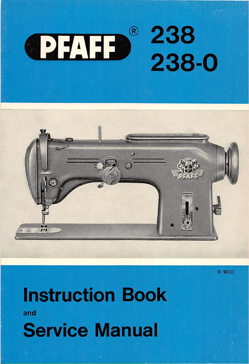
238
238-0
I
Instruction
and
Service
Book
Manual
R
9030
Page 2
/ hphee ^
(
PFAFF)
238
238-0
High-Speed
Organized
and
transverse
Zigzag
with
instruction
and
Service
Sewing
iink
take-up
rotary
hook
Manuai
Machine
Book
G-MPFAFFAG-KAISERSLAUTERN
BRANCH
Page 3
Foreword
This
Instruction
high-speed
of
answering
on
the
construction,
interested
as
possible.
The
instructions
be
much
appreciated
the
best
serviced
instructions
to
which
by an
affordabetter
you
book
contains
zigzag
all
questions
sewing
machines.
relatedtosewing
function
and
operatortogettoknow
for
mechanics
by all
maintenance
sewing
machine
expert.
as
simpleaspossiblle
We
will
have
understanding.
may
wishtomake.
much
vaiuable
Though
not
exhaustively, it offers sufficient information
operationofthe
her
machine
containedinthe
men
work
satisfactorily
made
every
and
have
We
welcome
Information
intendedasa
various
and
attain
maximum
second
servicing
only
partofthis
our
if it is
efforttorender
included
any
numerous
suggestions
about
Pfaff
238
and
full-scale
textbook
mechanismstoenable
efficiencyasquickly
book
willnodoubt
sewing
machines
employed
the
presentationofthese
properly
since
illustrationsinorder
and
recommendations
238-0
capable
every
even
and
G.M.PFAFF
AG
Page 4
Page 5

Instructions
1.
Brief
Descriptionofthe
The
Pfaff 238
which has been redesigned to match
ward
appearance
for
high-speed
and
Operators
Pfaff
238
zigzag sewing machine Is an Improved version of
our
modern high-speed straight stitchers In out
sewing
performance.
the
Pfaff 138
Like the Pfaff 138, It Is organized with link take-up and transverse rotary sewing hook
which features a special balancing collar In order to
The Pfaff 238 Is supplied in Models A
stitches
The
Model B machines
speedof3,500
If
about
As a
per
Inch.
permissible
desired,
top
s.p.m.
Model B
speedofthe
are
normally fitted for a stitch width of 11/64", or 4.5 mm, and a
machines
'A", or 6.0 mm, and maximum
special
variety,
the
can
Pfaff
width of 5/32" and a sustained
and
machine
be fitted with a
speed
238
can
be
speed
of 3,800 s.p.m.
B for a maximum stitch length of down to 7
depends
of 3,200 s.p.m.
suppliedInModelAforamaximum
ensure
on
special
vibratlonless running.
the
model
and
parts
set
for a stitch width of
the
stitch
width.
top
stitch
2.
Setting
In
power
most
Up
Instanoes,
table
are
the
Machine
the
packed
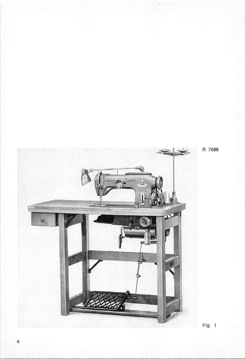
Pfaff 238 Is
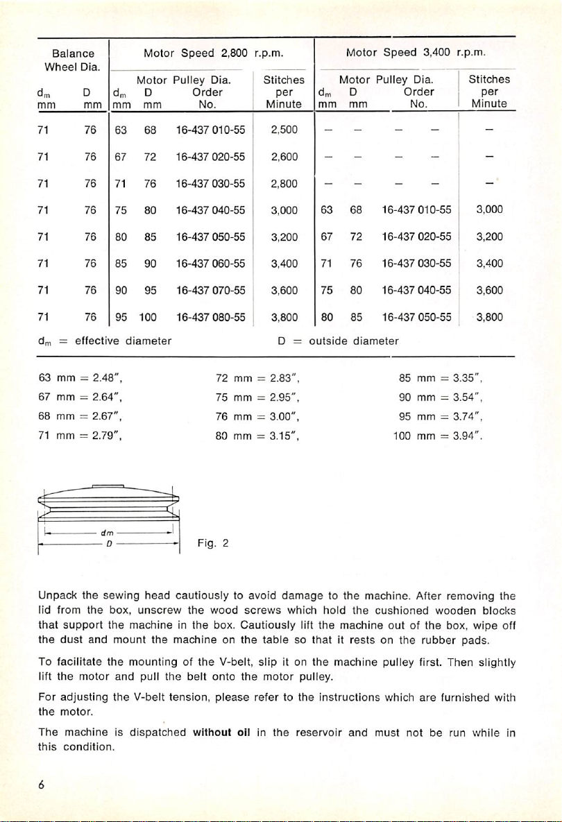
The machine Is driven by a
suit
local
requirements.)
PowerIstransmitted
or
10 mm,
When
and
The
as
mayberequired.
The
table
wide
connected
when
connected
motor
pulley
relationship
below:
from
and
conformingtoGerman
to a
50-cycle
to a
canbeeasily
between
separately.
Va-HP
the
motortothe
power
60-cycle
exchangedInorder
pulley
diameter
supplied
for Individual
power
drive.
Sewing
head
and
clutch motor. (Type of current and voltage optional to
sewing
supply,
power
supply,at3,400 r.p.m.
and
machinebymeans
DIN 2215
the
motor
to vary
maximum
standards.
runsata
the
sewing
of a V-belt 25/64",
speed
of 2,800 r.p.m.,
maximum
speedIsIndicatedInthe
sewing
speed,
Page 6
dm
mm
71
Balance
Whppj
nip.
D
mmdmmm
76
Motor
63 68
Motor
D
mm
Speed
Pulley
16-437
Order
No.
2,800
Dia.
010-55
r.p.m.
Stitches
per
Minute
2,500
dm
mm
-
Motor
Motor
D
mm
-
Speed
Pulley
-
Dia.
Order
No.
3,400
r.p.m.
Stitdies
per
Minute
71
71
71
71
71
71
71
dfn ~
63
67
68
71
mm
mm
mm
mm
76
76
76
76
76
76
76
effective
=
2.48",
=
2.64",
=
2.67",
=
2.79",
dm
- 0
67
71
75
80
85
90 95
95
100
diameter
72
16-437
020-55
76
16-437
030-55
80
16-437
040-55
85
16-437
050-55
90
16-437
060-55
16-437
070-55
16-437
080-55
72
75
76
80
Fig.
2
mm
mm
mm
mm
=
=
=
=
2,600
2,800
3,000
3,200
3,400
3,600
3,800
0 =
2.83",
2.95",
3.00",
3.15",
- - -
- -
-
68
63
67
72
71
76
75
80
80
85
outside
diameter
16-437
010-55
16-437
020-55
16-437
030-55
16-437
040-55
16-437
050-55
85
mm=3,35",
90 mm = 3.54",
95 mm =
100
mm=3.94".
-
-•
3,000
3,200
3,400
3.600
3,800
3.74",
Unpack
lid
that
the
To
lift
For
the
The
this
the
sewing
from
the
box,
support
dust
facilitate
the
adjusting
motor.
and
motor
the
mount
the
the
machineisdispatched
condition.
head
unscrew
machineinthe
the
machineonthe
mountingofthe
and
pull
the
V-belt
tension,
cautiouslytoavoid
the
wood
screws
box.
Cautiously
tablesothatitrestsonthe
V-belt,
slip
belt
onto
the
motor
please
refertothe
without
oil in
damagetothe
which
hold
lift
the
it on
the
pulley.
instructions
the
reservoir
the
machine
machine
and
machine.
cushioned
outofthe
pulley first.
which
must
not
After
rubber
are
removing
wooden
box,
Then
furnished
be
run
wipe
pads.
while
the
blocks
off
slightly
with
in
Page 7
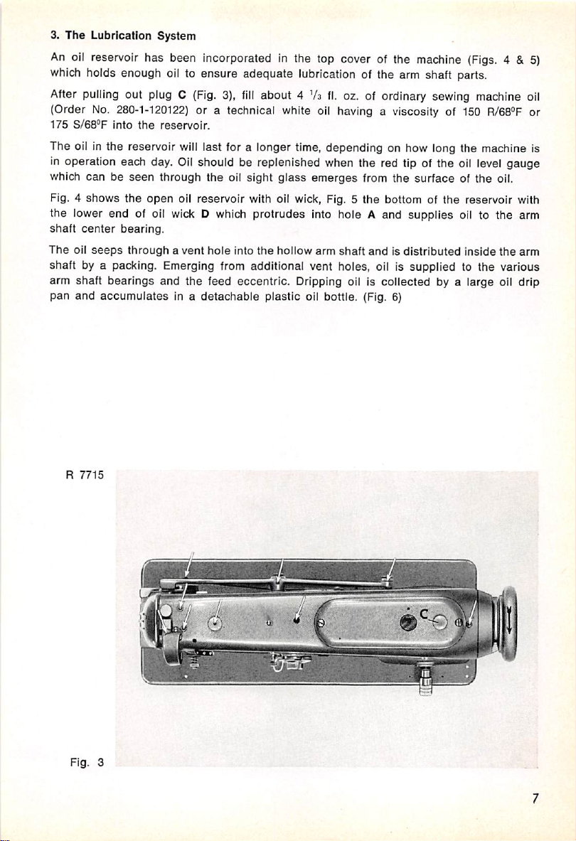
3.
The
An
Lubrication
oil
reservoir
System
has been
Incorporated
in the top cover of the
machine
(Figs.
4 &5)
which holds enough oil to ensure adequate lubrication of the arm shaft parts.
After pulling out plug C
(Order
No.
280-1-120122)
175
S/es'F
Into
the
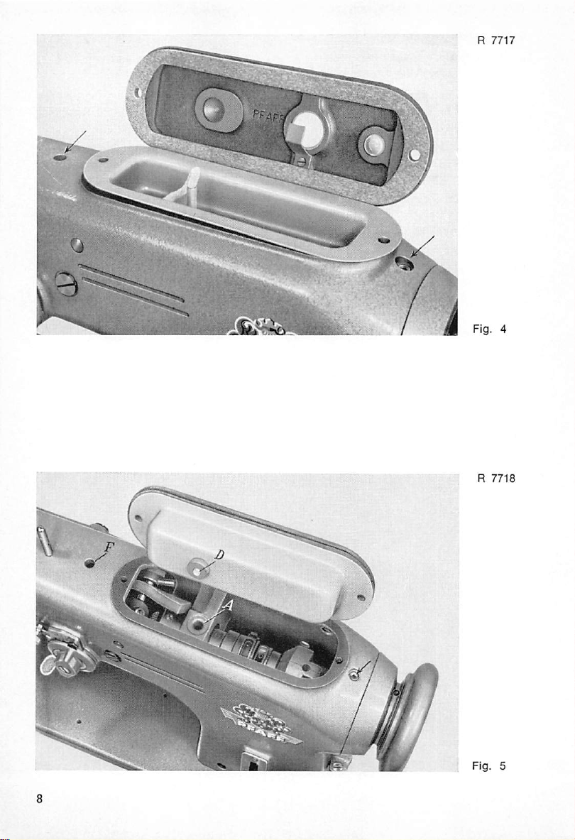
The oil in the reservoir
in operation each day.
which can be
Fig. 4 shows the
the lower end of oil wick D which protrudes into hole A and supplies oil to the arm
shaft
center
The
oil
seeps
seen
open
bearing.
throughavent
(Fig.
3),
fill
about 4Vsfl.
or a technical white oil having a viscosity of 150
reservoir.
will
last for a longer time, depending on how long the ma<^ine is
Oil
should be replenished when the red tip of the oil level gauge
through the oil
sight
glass
oz. of ordinary sewing machine oil
emerges
from the
surface
of the oil.
R/68°F
oil reservoir with oil wick, Fig. 5 the bottom of the reservoir with
hole
into
the
hollow
arm
shaft
andisdistributed
inside
the
arm
shaft by a packing. Emerging from additional vent holes, oil is supplied to the various
arm shaft
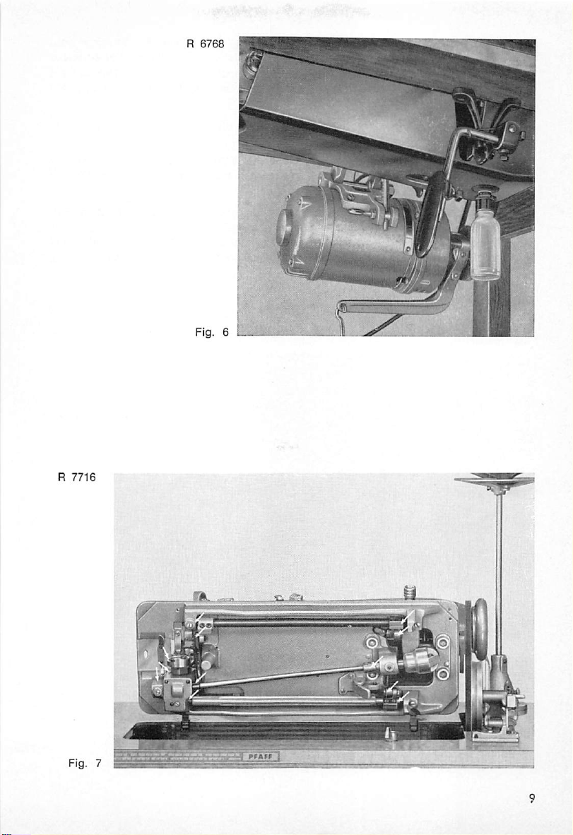
pan and
bearings
accumulates
and the feed eccentric. Dripping oil is collected by a large oil drip
in a detachable plastic oil bottle. (Fig. 6)
or
R
Fig.
7715
3
Page 8
Page 9
Page 10
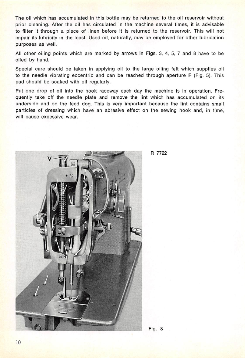
The
oil
which
has
prior
cleaning.
to filter it
Impair
its
purposes
All
other
oiledbyhand.
Special
to
the
needle
pad
shouldbesoaked
Put
one
quently
underside
After
throughapiece
lubricityinthe
as
well.
oiling
points
care
shouldbetakeninapplying
vibrating
drop
of oil
take
off
the
andonthe
particlesofdressing
will
cause
excessive
accumulatedinthis
the
oil
has
circulatedinthe
of linen
least.
Used
which
are
markedbyarrowsinFigs.
with oil
into
needle
feed
which
wear.
eccentric
the
and
regularly.
hook
plate
dog.
Thisisvery
haveanabrasive
bottle
before
oil,
can
raceway
and
maybereturnedtothe
machine
it is
returnedtothe
naturally,
remove
oil to
be
each
the
reached
the
maybeemployed
large
through
day
the
lint
Important
effect
on
several
3, 4, 5, 7
oiling felt
machine
which
because
the
sewing
R
7722
oil
reservoir
times,
it Is
without
advisable
reservoir. This will not
for
other
lubrication
and8havetobe
which
supplies
aperture
has
is in
accumulated
the
lint
hook
F (Fig. 5).
operation.
on
contains
and,intime,
oil
This
Fre
its
small
Fig.
8
10
Page 11
4.
Test-Running
the
Machine
Before you test-run the machine, carefully remove the rust preventative.
After
the
machine
chine with a
Before you plug the machine
piece
has
been
of fabric
lubricatedasinstructed
under
the
presser
In,
make sure that the voltage indicated on the rating plate
foot.
above,
test-run
the
unthread
ma
of the motor is within the tension range marked on the electric meter.
Also, make sure the machine pulley rotates in the proper direction, i. e. toward you. If
it
does
not, simply
exchange
the two wires at the motor terminals.
R
7685
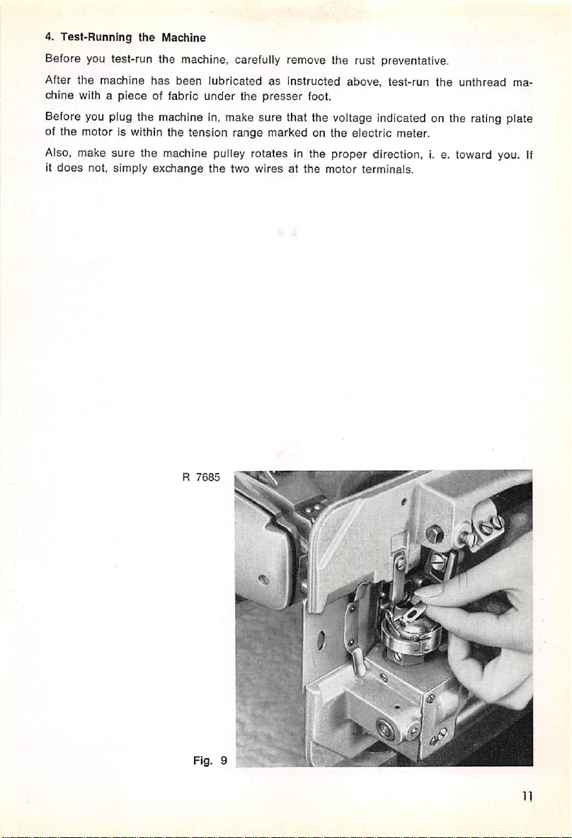
Fig.
9
11
Page 12
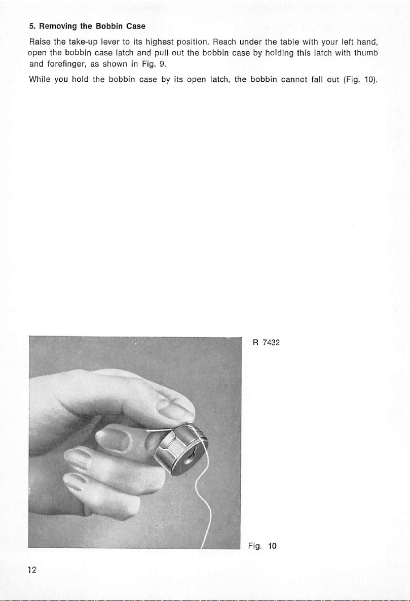
5.
Removing
Raise
open
and
forefinger,asshown
While
the
the
you
the
take-up
bobbin
hold
Bobbin
lever
case
the
to its
latch
bobbin
Case
highest
and
in Fig. 9.
case
pull
out
by its
position.
the
open
Reach
bobbin
latch,
under
the
table
casebyholding
the
bobbin
cannot
with
this
your
latch with
fall
out
left
hand,
thumb
(Fig. 10).
R
7432
Fig. 10
Page 13
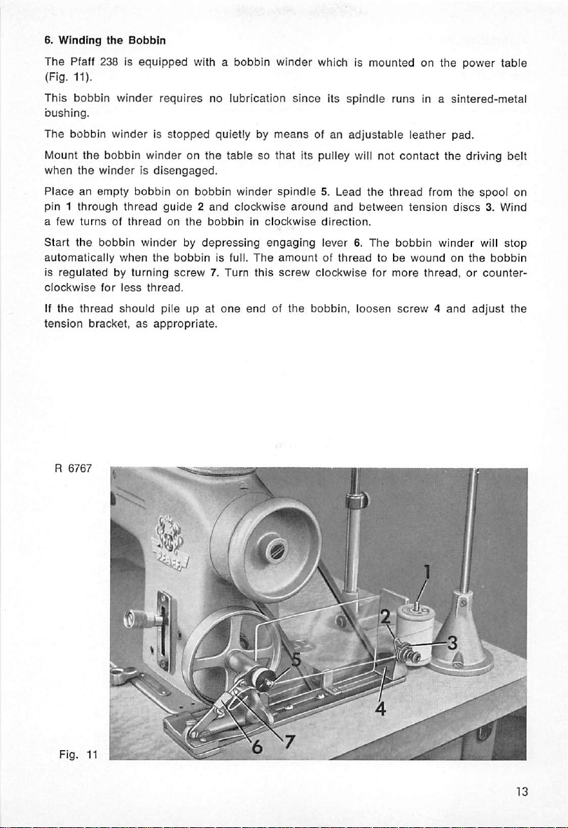
6.
Winding
The
(Fig.
This
bushing.
The
Mount
when
Placeanempty
pin1through
a
few
Start
automatically
is
regulatedbyturning
clockwise
If
the
tension
the
Pfaff 238 is
11).
bobbin
bobbin
winder
winderisstopped
the
bobbin
the
winderisdisengaged.
thread
turns
of
the
bobbin
when
for
less
thread
should
bracket,asappropriate.
Bobbin
equipped
requires
with a bobbin
no
quietly by
winderonthe
bobbinonbobbin
guide2and
thread
on
the
bobbininclockwise
winderbydepressing
the
bobbin
is full.
screw7.Turn
thread.
pile up at
lubrication
tablesothat
winder
clockwise
engaging
The
this
one
endofthe
winder
since
means
which is
of an
its
spindle
adjustable
mountedonthe
its pulley will not
spindle5.Lead
around
direction.
lever6.The
amountofthreadtobe
screw
clockwise
bobbin,
and
the
between
for
loosen
runs
in a
leather
contact
thread
from
tension
bobbin
winder
woundonthe
more
thread,orcounter
screw4and
power
sintered-metal
pad.
the
driving
the
spool
discs3.Wind
will
bobbin
adjust
table
belt
on
stop
the
R
Fig.
6767
m
».
IT
11
^^7
Page 14
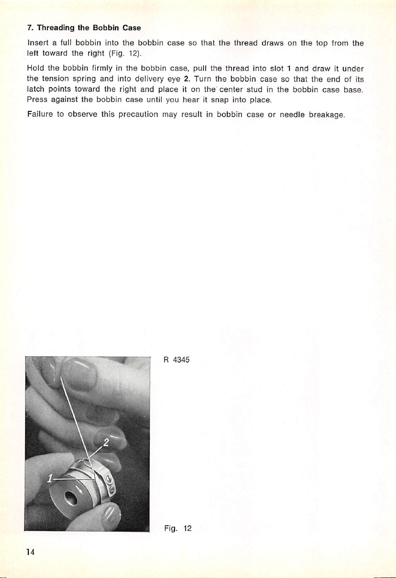
7.
Threading
Insert a full
left
toward
Hoid
the
the
tension
iatch
points
Press
against
Failure to
the
bobbin
the
bobbin
spring
toward
observe
Bobbin
right
firmly in
the
into
(Fig. 12).
and
the
bobbin
Case
the
bobbin
the
bobbin
into delivery
right
and
case
until you
casesothat
case,
eye
2. Turn
placeiton
hearitsnap
puli
this precaution may result in bobbin
the
the
the
the
center
thread
thread
bobbin
studinthe
into
place.
caseorneedle
drawsonthe
into
slot1and
casesothat
top from
drawitunder
the
bobbin
breakage.
end
case
the
of its
base.
R
4345
Fig.
12
14
Page 15
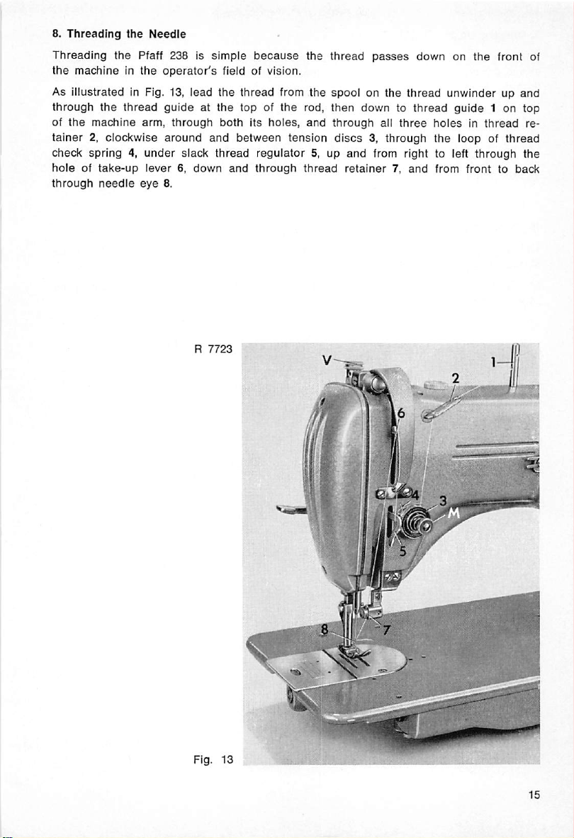
8.
Threading
Threading
the
machineinthe
the
the
Pfaff 238 Is
Needle
operator's
simple
because
field of vision.
the
thread
passes
down on
the
front of
As iiiustrated in Fig. 13, lead the thread from the spool on the thread unwinder up and
through
of
tainer
check
holeoftake-up
through
the
the
machine
2, clockwise
spring4,under
needle
thread
arm,
lever6,down
eye
8.
guideatthe
through
around
slack
R
both
and
thread
7723
top of
its
between
and
the
holes,
tension
regulator
through
rod,
then
and
through
discs3,through
5, up
and
thread
retainer7,and
downtothread
all
three
holesinthread
the
from right to left
guide
loop of
from
1 on top
re
thread
through
fronttoback
the
Fig. 13
Page 16
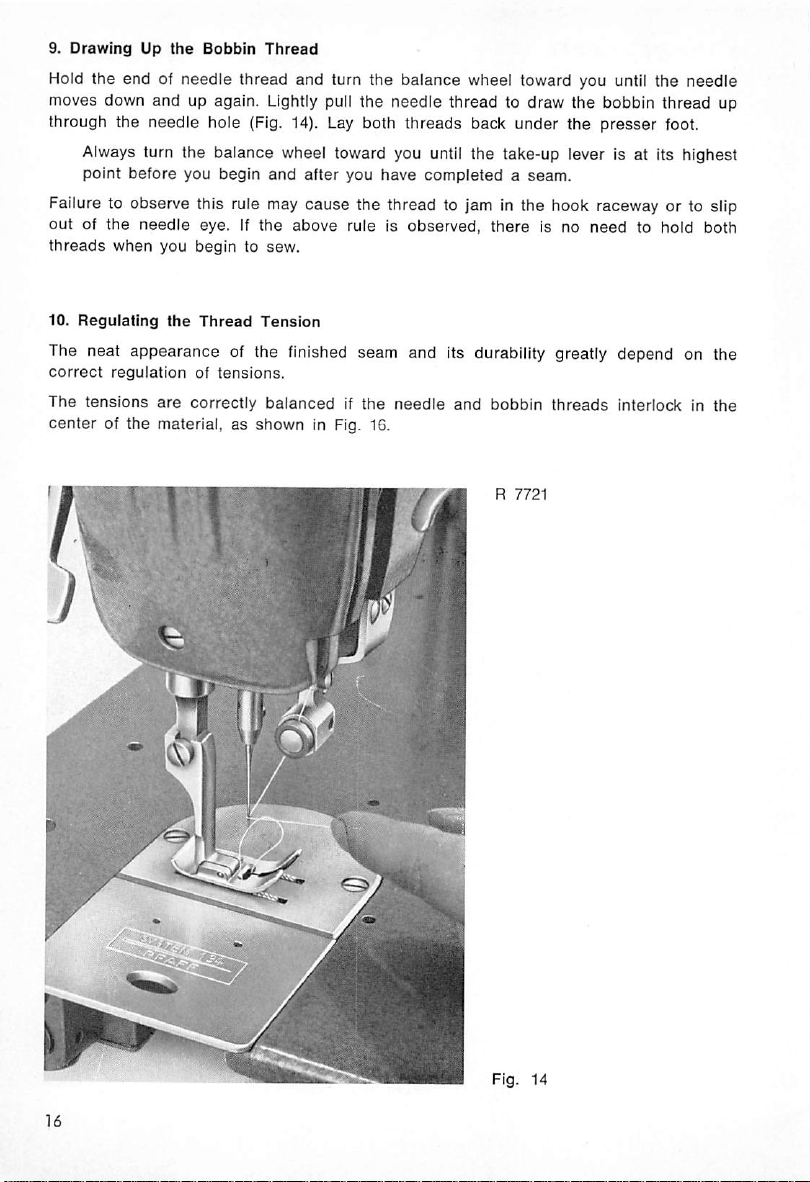
9.
DrawingUpthe
Bobbin
Thread
Hold the end of needle thread and turn the balance wheel toward you until the needle
moves down and up again. Lightly pull the needle thread to draw the bobbin thread up
through the
Always
point
needle
hole (Fig. 14). Lay both
threads
back under the
presser
foot.
turn the balance wheel toward you until the take-up lever is at its highest
before
you
begin
and
after
you
have
completedaseam.
Failure to observe this rule may cause the thread to jam In the hook raceway or to slip
outofthe
threads
10.
Regulating
needle
when you
the
eye. If
begin
Thread
the
to sew.
Tension
above
rule is
observed,
there
is no
need
to hold both
The neat appearance of the finished seam and its durability greatly depend on the
correct
The
centerofthe
regulation
tensions
of
tensions.
are
correctly
balancedifthe
material,asshown
in Fig. 16.
needle
and
bobbin
threads
interlock in
the
Fig. 14
Page 17

The needle thread
ed, by turning it counter-clockwise (Fig. 13).
The bobbin thread tension is regulated by means of the small hook screwdriver. Turn
tension screw z in for more tension, or out, for less tension
The tensions should be regulated according to the material to be sewn. Check to see
that the
the
stitches
stitches
zigzag pattern on the lop and
The grade of thread used plays an important part in obtaining a perfect seam on any
material. Sheer fabrics require a thin and soft thread, whereas stiff and resistant threads,
because of their low resilience, are unsuitable for almost any fabric.
You will
adjustment.
havetohave
are
should
tension
tightly
lieina
a little
is increased by
drawninwithout
straight
experienceinorder
bottom
line,
of the material
turning
tension
puckering
andinzigzag
without
to be
nutM
clockwise,
(Fig.
the
material,instraight
sewing,
should
kinking.
Fig. 15
able
to tell which
15).
and decreas
sewing,
formaperfect
tension
needs
Fig. 16
Fig.
Fig.
17
18
Page 18

In Fig. 17
In Fig. 18
You will
needs
bottom
havetodecide
to be
of
Always lower
is
raised,
it will
11.
Regulating
The
stitch
19).
This
appliestoboth
Turn
this
thumb
The
numerals
The
feed
regulator
action.
When
you
in
reverse.
leased
(Fig. 19).
either
the
upper
either
the
upper
tension
tension
is too tignt, or
is too weak, or
in every individual
adjusted,
the
fabric.
the
particulary when
presser
automatically
the
Stitch
bar
Length
before
release
you
lengthisregulatedbyturning
push
The
straight
nut
right
for
on
the
left of
leverispermanently
the
feed
regulator
lever
will
This
featureisparticularly
shorter
the
return
and
stitches,orleft,
slot
indicate
leverupbeyond
to its
case,ifeither
the
thread
adjust
the
tension.
thumb
zigzag
held
forward
useful
the
lower
tension
the
lower
tension
the
upperorthe
forms small knots or kinks on
the
upper
nut
tension.
S on
the
When
feed
sewing.
for
longer
stitches.
the
stitch
lengthinmillimeters.
downinforward
the
feeding
for
feeding
zero
mark,
position
backtacking.
the
automatically,
too weak.
too tight.
lower
tension
the
presser
regulator
positionbyspring
machine
lever
will
when
top
or
bar
(Fig.
feed
re
•mi
R
7720
Fig. 19
Page 19

12.
Regulating
The
stitch
machine
millimeters.
When
pointer
When
you
makes
the
With
the
about
3/16" or
There
is a
ScrewBservestolock
If
you
set
fixed
and
this, knob G
tacking
wider
zigzag stitch.
gageinnotch
automatically.
Switching from
stitch
width
the
Stitch
widthisregulated
arm
(Fig. 20).
Z is
setonzero,
turn
knob
zigzag
stitch.
zigzag
knobatthe
V4"
(4.5 or 6.0 mm) wide,
small
lug on
the
zigzag
will
notbedisturbedbythe
canbejerkedtozero
the
end
of a
Returnedtothe
R of
straight
can
be
done
Width
by
G to
The
numerals
the
extreme
turning
the
left,
knobGwhichislocatedinthe
on
the
zigzag
scale
machine
the
stitch
left
sews
width
of its
straight.
increases
scale,
dependingonthe
the
undersideofpointerZwhich
this
slideinposition.
knobon2
and
tighten
screwB,for
vibrationsofthe
seam.Bythe
slideSso
when a few
same
middle of
that
the
straight
token,
the
previous
stitches
knobGcanbejerkedtothe
zigzag
stitch
to zigzag stitchingaswellaschanging
while
sewing.
indicate
gradually
the
machine
machine model.
engages
instance,
machine
havetobe
scale,
width
the
will
in a
the
when
sewing.Inspite
pointer
setting
the
stitch length
middieofthe
stitch
width
and
the
machine
make
stitches
notchofslide
stitch
width
made
in back-
left for a
Z will
again
willberestored
and
in
S.
is
of
en
the
R
7719
Fig.
20
Page 20

13.
Setting
LeverHcanbesetinnotch
to
the
With lever H In notch I,
straight
When lever H is
sewing,
With lever H in notch
straight
The
tion, however, raise the needle
Failure to
14.
Regulating
the
Needle
leftorrightofthe
sewing,
and
set
and
swings
sewing,
needle
and
position can be
observe
the
Position
I, IIorIII
needle
plate
the
needleisat
swingstothe
in notch II, the
both
waysinzigzag
III,
the
swingstothe
right in
needleiscenteredinthe
needle
left in
changed
out
of the fabric before you change the needle position.
this precaution may
Pressure
on
the
Material
and
servestomove
slot.
the
extreme
zigzag
stitching.
stitching.
is at
the
extreme right of
zigzag
stitching.
while sewing. When
cause
bending or breaking of
the
needle
left of
the
needle
the
the
machine is not in
from
the
center
needle
plate
slot
plate slot in straight
needle
plate slot in
opera
the
needle.
Smooth feeding and uniform stitching greatly depend on the correct amount of presser
foot
pressure.
a
direct
To increase the pressure for heavier fabrics, turn screw V in, and to
for lightweight materials, turn it
When stitching delicate and
Staggering
resultofincorrect
stitches
pressure
sheer
and
feed
out
markings on
regulation.
(Fig. 13).
the
undersideofthe
ease
fabric
the pressure
fabrics, feed a piece of tissue paper under the mate
are
rial to protect it from the feed points and prevent puckering. This paper can be readiiy
pulled
away
after
sewing
has
been
completed.
in
15.
Selecting
The
Pfaff
Model A machines
sewing
Model B machines
4 mm, longer
materials.
Pfaff 238-115
the
238isfitted
speed,
cording
and
and
Correct
Needle
with
round-shank
use
short System 133
hence
assure
neat
are
equipped
are
available in a number of different point styles to suit various
machines
with System 134 R
use
needles.
needles
seams.
System
which will not tremble, regardless ofthe
130 B
needles
needles
which
with a
are
about
smaller
5/32", or
shank
dia
meter. Pin tucks are made with two System 130 Br and Bl needles which are placed be
tween the needle holder jaws with their flat
tightening the needie
gauge
regulating screw.To make three System 134 RFr RFI
sides
facing,
and
are
secured
in position by
needles
having a flat on the right and left side of the shank, respectively, and two System 134
Rfmc
The
or
0.8
20
needles
number
blade,
mm,
whose
shankisflattened
indicating the
expressedinhundredths
its
sizeIs80.
needle
on
both
sides.
size is identical with
of millimeters.
Thus,ifthe
the
diameter of
diameter
the
needle
of a
shaft,
needle
is
Page 21

The
appearanceofthe
needle,
Lightweight
marks.
When
used
Select
Never
Only
vents
surfaced
synthetic
If an ordinary
thread
fabrics
thick
threadisused
in a thick
the
proper
use
rusty
the
exceptional
thread
needle
threads
and
needle
needle
needles.
breaking.
will
which
needle
seams,werecommend
which
maybeobtained
finished
fabric.
seamIsdependentonthe
shouldbesewn
in a
thin
may
cause
and
thread
quality of
When
overheat
should
that
from
the
operatingatthe
quickly
are
very
overheat
you
useasuperfinished,
us.
with a thin
needle,
needleinordertoprevent
the
thread
skippingofstitches.
sizes
from
the
needle
finish
ensures
high
and
burn
the
sensitivetoheat
when
sewing
correct
is likely to
chart
below:
trouble-free
speedofthe
thread.
and
resistant
Thisisparticularly
fuse
easily.
materials or stitching long
chromium-plated
relationship
ugly
break.
Thin
sewing
Pfaff 238, a
System
between
and
134
needle
thread
pre
rough-
true
needle
of
Needle
100
110
Needle
Size
60
70
80
90
Cotton
130/3
130/4
100/3
100/4
80/3
80/4
70/3-60/3
70/4-60/4
50/3-40/3
50/4-40/4
30/3
30/4
30/6
and
140/3
120/3
100/3
Silk
80/3
70/3
60/3
Thread
Chart
Synthetic
200/3-150/3
140/3-120/3
120/3-100/3
100/3-
80/3
70/3
60/3
Linen
70/3
60/3
50/3
21
Page 22

16.
Changing
(1)
Raise
(2) Loosen
(3) Pull
(4) Insert a new
it will
(5)
Tighten
17.
The
The Pfaff 238 is organized with a System 134 double-revolution,
the
the
out
the
go.
the
Sewing
the
needle
needle
old
Make
needle
Hook
Needle
needle.
needle
sure
bar
set
set
to Its
Into
the
highest
screw,
the
long
screw
point.
using a
small
openingofthe
groove
faces
securely.
screwdriver
needle
toward
you.
clamp
for
this
and
transverse
purpose.
push
it upasfar as
rotary hook
which moves counter-clockwise and is equipped with a special balancing collar to
ensure
vibrationless
runningofthe
machine.
This sewing hook features a welcome improvement over the old-type hook In that its
gib is held In place by one screw instead of the three screws used previously. This
screw
(e in Fig. 21) is located at
small recess in the body of the hook.
the hook, or in
securedbyone
the
two
parts
The springiness of the redesigned gib prevents bobbin
thread
jamming.
case
of thread jamming, is exceedingly simple. Since the hook gib is
screw
and the hook thread guard, or thread pull-off flange, by three,
cannot
possiblybeconfused.
Furthermore,
make it impossible to get at the gib screw.
the
one
end of the hook gib while its
Removal
machine
of the gib for a thorough cleaning of
will
neverbeblocked
All
this
will
other
end
enters
case
breakage
to an
as a result of
extent
which
eliminate the necessity of re
will
moving the hook, resetting the hook shaft and retiming the sewing hook, a job for which
a
mechanic
normally
hastobe
called.
a
Fig.
21
Page 23

18. Pfaff 238-14 for Eyeletting
The Pfaff 238-14 eyeletting machine is supplied in two varieties. Whiie on
238-14/1 the
equipped
Operation of the Pfaff
Put needle position lever H in notch
left in
with
zigzag
work
is turned about the center stud by hand, the
positive
sewing.
rotary
238-14/1
feed.
is exceedingly simple.
III
(Fig.
20) so that the needle swings from right to
Pfaff
the
Pfaff
238-14/2 is
Select a slide with a stud diameter which suits the size of the eyelets you want to
make. Push this slide into the siot of the needle plate and position it so that the needle
will be just inside the groove in the center stud when it
Punch out the hole for the eyelet, using
Make
sure
the
punch
diameterissmailer
one
of the punches suppiied with the machine.
than
the
terial will fit around the stud snugly. Slip the fabric over the
down
evenly
all
around.
Select
the stitch width according to the thickness of
sew
desired. To
work
around
Another
Put
tate
slidesothat
slide
procedure
needle
the
balance
mustberepositioned
This setting affords
the
process.
straight stitches (before sewing the eyelet
eyelet
with a few tying
a neat eyelet, run the machine at a uniform
the
center
stud
evenly.
which maybeappliedisas
position
lever
wheel
thereisa
the
H in
notchIand
until
the
small
clearance
whenever
advantage
needle
that
turn
descends
between
the
stitch width is
the
stitch width
Thus, it is possible to join multiple plies by sewing
seam
stitches
(with knob G
set
descends
center
on the right of its throw.
stud
diametersothat
center
the
material
speed
follows:
knobGto
on
the
the
needle
changed.
the
desired
leftofits
and
canbechanged
with zigzag stitches)
on "O").
stud
and
and
the type of eyelet
while turning the
stitch
throw.
Position
the
center
several
around
the
and
to finish the
the
push it
width.
stud.
times
hole with
ma
Ro
the
The
in
To
prepare
er
foot
The
1
Eyeletting
1
Needle
1 Eyeletting
1 Eyeletting
the machine for eyeletting,exchange the ordinary
for
the
special
set
of organizational parts for
foot
plate
slide,
slide,
needle
No.
41500
No.
42362
w/4 mm -dia.
w/5 mm -dia.
plate
and
subclass
stud.
stud.
eyeletting
No. 42359
No. 42380
-14/1 machines consists of the following:
1 Eyeletting slide, w/6 mm -dia. stud. No. 42361
1
Clamping
1
Punch,3mm
1
Punch,4mm
1
Punch
block
screw
-dia.,
-dia..
No.
No.
799
No.
No.
32424710
41664
41665
foot.
needle
plate and
thepress-
23
Page 24

42359 42360
32424710
ii
42361
799
The
following
1 Eyeletling slide, w/3 mm -dia. stud, No. 42358
1 Eyelelting slide, w/7 mm -dia, stud, No. 46159
1 Eyeletting slide, w/8 mm -dia. stud. No. 46162
1
Punch,
2 mm = 5/64"; 3 mm = 1/8"; 4 mm = 5/32";
5 mm = 3/16": 6 mm = 1/4"; 7
8
mm=5/16".
2 mm
parts
dia.,
will
be supplied on special request:
No.
41663
mm
= 9/32";
Page 25

Operation of the Pfaff
238-14/2
is basically the same as of the Pfaff
238-14/1,
except that
the material is turned about the center stud by a positively driven rotary feed rather
thanbyhand.
The
Pfaff
238-14/2isavailable
Group I for
Group
Ail that is required to
center
studs
II
for
center
studs
change
to exchange the slide with
When
changing
exchanged
few
minutes.
The
mechanical
over
from
in addition. This
setupofthe
in
two
varieties:
of from 5/64" to 15/32" {2-10 mm) dia.
of from 7/16" to 23/32" (11-18 mm) dIa.
the size of the eyelet within
center
stud and the
group
I to
group
conversion
rotary-feed eyeletting unit is illustrated in Fig. 22.
job
presser
II, or vice versa,
canbeperformed
one
of the
ring disc In the eyeletting foot.
the
rotary feed
by every
above
mechanic
groups
has
to be
in a
is
Fig.
22
Page 26

19. Pfaff 238-115 for
Cording
The Pfaff 238-115 is specially fitted for multi-needle decorative stitching and cording
operations. To suit different requirements, this machine is supplied in a number of
varieties equipped with different needle holders, cording plates and cording feet, as
follows:
238-115/1-6
Two
and three-needle ornamental stitching in straight or narrow zigzag
stitch; needle plate slot 3/16" or 1/4" (4.5 or 6.0 mm) wide; needle hold
er
fitted with
double-threaded
screw;
System
130 B
needles.
238-115/1-45 Two or three-needle air cording; needle holder fitted with double-thread
ed
screw;
238-115/1-235
238-115/2-45
System
The
needle
for maximum needle gauges of 1/8", 3/16", and 1/4"
6.0 mm).
Same as
and
238-115/1-45,
130Blneedles.
Two-needle air cording in needle gauges
130Brand
gauge
130 Bl
canbeadjusted
but
fitted
needles.
by turning only
to make
filled
one
screw.
(3.0,
cording: System 130 Br
ranging
from
1/16"
Available
4.5 and
to 1/4"
(1.4 —6.0 mm); needle holder jaws individually adjustable; available for
238-115/2-245
maximum
System
Same as
needles.
needle gauges of 1/8", 3/16", and 1/4"
134 R
needles.
238-115/2-45,
but fitted to make
(3.0,
4.5 and 6.0 mm);
filled
cording; System 134 R
238-115/4-45 Four-needle air cording on gloves, etc.; needle holder fitted with double-
238-115/5
26
threaded screw; four needles
and
are
of
outer
dles
7/32"
and
This
abie
class
needles.
clamped
needles
are
flattened on both sides; over-all width of triple cording 3/16" or
(4.7
134
Rfmh
variety
needle
-6, -45
in position by tightening
are
flattenedonone
or 5.4
mm);
needles.
is supplied on special request
holders
and
for 1, 2
-245
organizations;
are
inserted in slot of needle holder jaws
double-threaded
side,
while
System 134 Rfr and 134
only.
and3needles;
System
canbecombined
130 B or 130 Br
shanksofinner
RFI
or System 134
Fitted
with
screw;
exchange-
and
with
shanks
nee
Rfmc
sub
130 Bl
Page 27

Listed on the opposite
serts
and
cording
four
needle
Since
terial to be
a
certain
plate
the
compositionofthe
sewn,nohard-and-fast
cording
page
are
feet which may be
inserts
and
four
individual
size.
a variety of feed dogs, needle piates,
used
on Pfaff 238-115 machines.
cording
rule
feet
are
standard
parts
sets
dependsonthe
can
be givenasto which
with
each
thicknessofthe
parts
needle
One
machine.
are
piate in
needle
required
piate,
ma
for
Fig. 23 shows the Pfaff 238-115/1-245 fitted with needle plate insert and adjustable needle
holder
Apart
needle
narrow
simply
for filled
from
zigzag
needle
insert
cording
cording
seams.
gauge,ifthe
one
work,
needle
work.
the
For
between
Pfaff 238-115
this
typeofwork,
machine
is tobeused
the
needle
can
alsobeused
it is
holder
set
foranarrow
for
jaws.
for
sewing
single-needle
ornamentai
zigzag
zigzag
stitch
two-
and
stitching,
a
R
Fig.
6365
23
Page 28

Organizational
Parts
for
the
Pfaff 238-115
Needle plate, for 1/8", of 3.0 mm, needle
Feed dog, for 1/8", or 3.0 mm,
Needle
plate, for 3/16", or 4.5 mm,
needle
Feed dog, for 3/16", or 4.5 mm, needle
Needle plate, for 1/4", or 6.0 mm,
Feed dog, for 1/4", or 6.0 mm, needle
gauge
needle
needle
gauge
gauge
gauge
gauge
gauge
Cording slide, w/o ridge
Cording slides, w/ ridges from 1/32" to 9/64", or
0.8 to 3.6 mm
Cording slides, w/
or
0.6to2.4
Cording
mm,
slide
high,insteps
cord
ducts
dia.,insteps
set
screw
of 0.2 mm
from 1/32" to 3/32"
of 0.2 mm
Cording foot, w/ 11 grooves, 0.6 x 0.8 mm,
for 1/8", or 3.0 mm, needle gauge
Cording foot, w/ 11 grooves, 0.8 xl.O mm,
for 1/8", or 3.0 mm, needle
gauge
Cording foot, w/ 9 grooves, 1.0 x 1.2 mm, for
1/8", or 3.0 mm, needle
gauge
Cording foot, w/ 9 grooves, 1.2 x 1.4 mm,
for 3/16", or 4.5 mm, needle gauge
Cording foot, w/ 7 grooves, 1.6 x 1.6 mm, for
3/16", or 4.5 mm, needle gauge
Cording foot, w/ 7 grooves, 2.0 x 1.8 mm, for
3/16", or 4.5 mm, needle gauge
Cording foot, w/ 5 grooves, 2.4 x 2.0 mm, for
3/16", or 4.5 mm, needle
gauge
Cording foot, w/ 5 grooves, 2.8 x 2.4 mm,
for 3/16", or 4.5 mm, needle
gauge
Cording foot, w/ 3 grooves, 3.4 x 2.8 mm, for 1/4"
or
6.0 mm,
needle
gauge
No.
26835
No.
26833
No.
26885
No.
26883
No.
26892
No.
26890
No.
26902
No.
26900
X
heightofridge
No.
26904
X
cord
duct
dia.
No.
564
No.
51263
No.
51265
No.
51267
No.
51269
No.
51271
No.
51273
No.
51275
No.
51277
No.
51279
Cording foot, w/ 3 grooves, 4.5 x 3.2 mm, for
1/4", or 6.0 mm,
28
needle
gauge
No.
51281
Page 29

•AH
miiitniitniitii
t
S>.
Page 30

Page 31

20. Pfaff 238-130 with
Knee-Operated
Stitch Width Control
This machine features a knee-operated stitch
width
control
which
greatly facilitates such
operations as single-needle cording, eyelet embroidery and flat embroidery in the pro
duction of white goods, blouses, etc. (Fig. 24). A
presser
When
foot.
knee pressure is relieved, the stitch
"0" by spring action.
On the Pfaff 238-130 the lug on the underside of pointer 2 fits snugly into notch R of
slide
S (Fig. 20).
be varied by
knee
For
action
this
reason,
while sewing.
screwBmustbeloosened
second
width
control is automatically returned to
treadle
when
serves
the
stitch
to raise the
width
is to
Screw B is tightened to lock the slide for any desired stitch width so that the operator
need not press against the knee lever continuously when sewing satin-stitch seams
with a uniform stitch width
ordinary
attachedtothe
zigzag
sewing, To
presser
throughout,inthis
this
end,
bar.
way,
an ordinary
the
zigzag
Pfaff 238-130
foot with a
canbeused
smooth
sole
for
is
R
Fig.
7213
24
31
Page 32

Satin-stitch
sole
seams
and
permitstosew
If a more prominent
51353
which
has
three
Interesting
H in
from
effects
notch
I, ilorMi,sothat
the
middle.
are
made
with
hinged
bends
without
seam
is to be produced, we recommend to
cord
ductsinfrontofthe
zigzag
compressing
canbeobtainedbyvarying
the
needle
swingstothe
foot No. 51355 which
the
seam.
needle
hole.
the
needle
position,1.e. by
right,tothe
hasarelieved
use
sewing foot No.
putting
left,orboth
lever
ways
Page 33

Page 34

21.
Trouble
Shooting
Machine
Cause:
1.
2.
3.
4.
5.
6.
7.
Skips
incorrect
Wrong
Needle
Needle
Needle
Needle
Needle
8. Hook
9.
Hook
10. Material
11.
Thread
Thread
Cause:
Breaks
1. Any of
2.
Thread
3.
Poororknotty
4.
Thread
5.
Poor-quality
6.
Thread
7.
Burrsorsharp
8.
Thread
Thread
9.
10.
Blunt
Stitches
threading.
needle.
inserted
too
too
bent.
set
set
timed
incorrectly.
fine
for
thick
too
highortoo
too far from
Incorrectly.
tackyorheavily
twisted
the
tension
too
above-mentioned
too
thread
rotten
duetoextremely
thread
jammedInhook
edgesonneedle
snarledupon
check
spring
needle
point.
for
the
the
much.
tight.
used.
used.
spool
timed
thread
thread
needle
dressed.
race.
used.
used.
low.
(correct
conditions
long
plate
pin.
Incorrectly.
clearance
may
and
dry
slot.
.004", or 0.1 mm).
cause
thread
storage.
breakage.
Needle
Cause:
1.
2.
3.
4.
5.
6.
7.
8.
9.
10.
34
Breaks
Bent
Thread
Hook
Upper
Needle
Needle
Machine
Hook
Needle
Thread
needle
strikes
too
heavy
setting
disturbed
tension
too
deflectedbyhard
bent
because
feeds
while
set
too
closetoneedle.
too
fine
for
snarled
uponspool
hook
point.
for
needle
used.
after
thread
jamming.
tight.
spots
In material.
materialIspushedorpulled.
needleIsdowninmaterial.
the
fabric.
pin.
Page 35

Machine
Cause:
1.
2.
3.
4.
5.
6.
Overheating
Cause:
1.
2. V-belt
3. Full
Feeds
improperly
Feed
dog
set
too
Feed
teeth
too
Feed
dog
unsuitable
Incorrect
pressure
Accumulationsofpacked
Blunt
feed
points.
No
oilInreservoir.
too
tight,
weightofmotor
low.
fine
on
causing
for
for
material.
pulls
the
material.
the
worktobe
lint
excessive
down
between
pressureonarm
V-belt
because
performed.
feed
teeth.
belt
shaft
take-up
bearings.
hanger
has
come
loose.
35
Page 36

Pfaff
238-0
High-Speed
Zigzag
Sewing
Machine
22. Brief
With
for a more efficient high-speed sewing machine. The mechanical setup of the Pfaff
closely resembles that of the job-proven Pfaff
increased
ments:
fvlaintenance-free anti-friction bearings instead of plain bearings at both ends of the arm
shaft, sealed-for-life needle bearings in the take-up lever assembly, wick-lubricated
needle bar bushings, and a separate
sewing
With
en for Pfaff 238
Descriptionofthe
the
introduction
from
3,800to4,500
hook.
of its
Pfaff 238-0
01.
238-0,
s.p.m.
Pfaff
through
wick
has met the
238,
the incorporation of the
and reservoir lubrication system for the
demand
while its sewing speed has been
of the
sewing
following
industry
improve
238-0
the exception of Chapter 3, entitled "The Lubrication System", all instructions giv
applytothe
Pfaff 238-0
also.
R
9401
f"i9- 26
Page 37

23. The Lubrication System of the Pfaff 238-0
From
the
oil
reservoir
the
arm
shaft
center
the
two
needle
bar
tube has
bar
From
necessary.
The
wick
The
wick-fiiied
tube
oii through an oii duct into the hook raceway.
This
are
The bed plate reservoir holds 5 1/3
cation.
reservoir
bined
gasket.
The
oil
The
illustrations on pp. 4-8.
been
bushings.
timetotime,
high
speed
and
reservoir
sewing
piastic
into
the
reservoir
properly
The
and the
with
the
Pfaff
238-0
No.
2801-120122
oiling
points
hookislubricated
oii
lubrication
lubricatedatall
oii
weekly
usesthe
under
the
top
coverofthe
bearing
bushingsinthe
incorporated
check
of the
lubrication
tube
retainer
level
can be
oilbereplenished.Ifnecessary.
or a
which
and
which
the
machine
conducts
ringonthe
system
times.
checked
cleaning
same
technical
have
the
needle
conducts
oii
levelinthe
has
system
from
oiitothe
minimizes
fl.
of the
oii
as the
white
to be
zigzag
bar
madeitnecessarytoincorporateacombination
for
the
the
oii
hook
sewing
oz. of oil
throughanoil
machine.Totop up the
Pfaff
oil
havingaviscosityof150R/68®For175
lubricated
maintenance
machine
mechanisminthe
frame.
For
this
oii
from
the
oii
oii
sight
glass
transverse
reservoir
saddle
hook.
which
238,i.e.
manually
rotary
under
whenceitflows
Centrifugal
and
will
last for several weeks'
sight glass on the
Checking
either
are
oiiissupplied
machine
arm,
not
but
only
purpose,awick-fiiied
reservoirtoboth
and
the
hook.
bed
replenish
plate
the
(Fig.
throughacopper
force
then
flings
ensures
the
markedbyarrows
oil
level
oil,
you
ordinary
that
all
vital
bottom
maybecom
do not lose the
sewing
machine
S/68°F.
also
piastic
needle
oil,
26).
the
parts
lubri
of the
in the
to
to
if
A
37
Page 38

Instructions
24.
Timing
The
functions of
the
balanceofthe
ting
the
stitch to
from
the
time
until
the
needle
the
for
Thread
the
the
the
descending
reaches
Mechanics
Check
thread
needle
desired
thread
the
Spring
check
spring
after
tightness,
take-up
goods.
aretoassist
the
loop
and
in controlling
lever
beginstodraw
has
the
passed
take-up
around
the
slackofthe
the
R
7880
lever in taking up
the
bobbin,Inset
needle
thread
from
the
thread
spool
IjTj^irf J
Fig.
27
Page 39

The downward stroke of the thread check spring is limited by a stop on the tension
barrel and can be adjusted by rotating this barrel, as may be required.
To do this, insert a screwdriver into opening E (Fig. 27), loosen the tension barrel
screw
and, inserting
the
tension
To
adjust
If it
shouldbeimpossibletoturn
screwdriver,
barrel
the
loosen
barrel out of
thread
the
the
is in
check
the
tension
machine
screwdriver
the
correct
spring
barrel
and
slightly
position.
tension,
the
into
the
slotoftension
turn
tension
studinthe
set
screwinopening
loosen
the
tension
set
stud
tension
screw
stud
M, turn
M in
barrel
E (Fig 27),
at its
the
with
rear
the
tension
the
take
the
end. After
latter
aid
tension
set
until
barrel.
of a
the
tension barrel has been replaced in the machine, the stroke of the thread check spring
mustbereadjusted.
R
7887
Fig.
28
39
Page 40

Thread
and
regulator
down
Bysodoing,Itadapts
with
J (Fig. 28) Is
the
presser
barasthe
the
thread
mountedonthe
sewing
consumptiontothe
terial being sewn. As a result of this action,
when
thicker
Thread
setting
the
thread
correlate
spring not only
wards
Once
thread
resortingtotrial-and-error
The
thread
es
the
may be
it will still
portionsofthe
regulator J
the
thread
check
spring
the
thread
takesupthe
perpendicularly.
you
are
familiar with
can
regulator
be
can
regulator
the
material
adjusted
higher
be
adjusted
and
proper
pass
vertically
or lower
tension
amount
functions performed by both the check spring
regulator, you willbeabletomake
methods.
check
spring
is timed correctly If it Is through
goods.
Since
the
take-up
necessarytoIncrease
exertaslight
pull
lever of
the
strokeofthe
on
the
thread
foot
the
under
the
within
barrel
presser
check
after
bar
guide
passes
over
varying
spring
hastotakeupless
the
sewing
foot.
loosening
amountofthread
certain
settings
limits. It Is
so
of thread, but also pulls
the
proper
adjustment
acting
the
Pfaff 238
thread
when
makesarather
check spring
the
needle
collar
and
moves
up
IrregularitiesInthickness.
thicknessesofthe
ma
thread
screw
d (Fig. 28). By
to be controlled by
recommended
that
the
when
right
the
thread
the
away
needle
thread
and
without
check
up
the
reach
long stroke, it
somewhatsothat
enters
the
material.
to
25.
Timing
the
Sewing
Hook
To time the sewing hook correctly, we recommend that you use a needle rise gauge
which
canbeobtained
Begin by removing
(Fig. 20).
Rotate
stroke. Slip both the needle rise
needle
bar,
push
bar
frame,
and
tighten
Then pull out
the
the needle bar frame (Fig. 30). Loosen
and
rotate
the
sewing
needle.
At the
same
time,
between
40
both
parts
fromusunder
the
needle
plate
the
balance
the
gauge
wheel until
clampupagainst
the
clamp
and
cautiously turn the
hook on Its
set
the hookasclose to the needleaspossible, the proper
Order
Nos.
880136/01
and
setting
lever H In notch II
the
needle
has
gauge
(5/64", or 2.0 mm, thick and the clamp onto the
the
gauge
until
screw
securely
(Fig. 29).
balance
set
screws
K and T (Figs. 29 and 30, respectively)
shaft
until Its point Is
and
reached
the
latter
wheel until
opposite
being .004", or 0.1 mm (Fig. 31).
880137/00.
and
knob G on "0"
the
lowest point of Its
contacts
the
clamp
the
center
the
needle
contacts
line of
clearance
the
Page 41

Page 42

26.
To
the
the
Setting
set
the
balance
latter
the
Needle
needle
wheel until
ascends
BaratCorrect
bar at the correct height, turn knob G (Fig. 20) to "4" and rotate
the
on
the
left of its throw.
be positioned .04", or 1.0 mm,
If
adjustmentisrequired,
lower,asmayberequired.
loosen
hook
point is
above
set
Height
the
screw
opposite
Wheninthis
top of
the
m (Fig. 28)
the
needle
and
center
position,
eye {Fig. 31a).
set
the
R
7881
line of
the
needle
the
hook
needle
point
bar
when
should
higher
or
Wmm
Fig.
31a
Fig.
31
42
Page 43

27.
Changing
the
Sewing Hook
1. Remove needle, needle plate, feed dog and bobbin
2.
Loosen
3. Rotate the
4. Pull
5. With
replace
sure
position finger
6.
Time
securely.
7.
Replace
28.
1.
Remove
2.
Take
c (Fig. 28)
Pull
bracket
3.
Remove
bar
eccentric
pull
4.
Take
ing
5.
Rotate
be
6.
Loosen
7.
Loosen
8.
Place
Fig. 34.
it into
out
suppliedatextra
9.
Cautiously
up
hook
set
the
sewing
the
feed
the
there is a
the
feed
Dismantling
face
out
thread
back
complete
will not be
the
needle
out
lever
the
reached
take-up
set
the
Insert
the
screwsKand
balance
hook
dog
set
bobbin
clearance
and
sewing
hookasinstructedinChapter25and
dog
and
the
Thread
cover,
pressure
and
regulating
pull
regulator
outofthe
needle
disturbed.
studa.Then
bar
plastic
plugUon
assembly.
balance
through
crank
screw
P on
barofthe
the
threaded
hollow
hinge
wheel until the feed bar is at its highest point.
off Its
at Its
case
the
bottomofthe
needle
presser
the
presser
J (Fig. 28),
machine.
loosen
frame,
wheel
the
aperture
screw
take-up
pull-off
studofthe
T (Figs. 29
shaft.
highest
point,
push
position finger bracket. As you
of .024 to .036", or 0.6 to 0.9 mm, between the tip of the
position
plate.
Take-up
foot
(with
screw)
screw
and
remove
barupoutofthe
bar
frame
To do this,
screwf(Fig.
enclosing
the
backofthe
until
take-up
Q.
device
endofthe
presser
assemblysothat
on
link
across
take-up
loosen
the
needle
crank
the
backofthe
stud
pull-off
bar
28)
(Fig. 33).
the
link
of its mount. (The pull-off device is available under No. 880141/00 and will be
cost.)
pull
out
the
crank
and
needle
take-up
bar
lever
connecting
assembly,
link.
and
30).
the
slotinthe
and
presser
machine.
guide
set
and
bar,
machine
screw
face
device
and,inthis
including
case
position finger bracket.
new
hook
onto
replace
bobbin
tighten
needle.
bar
spring.
collar
and
the
height
screw
b (Fig. 36)
pull
out
hinge
forward
arm
Q in
machine
sideofthe
through
outofthe
(Fig.
32)
the
needle
arm
machine,asshown
the
way, pull
the
take-up
the
this
case
set
Loosen
presser
settingofthe
studg.This
and
(Fig.
holeinthe
hook
shaft
bracket,
base
make
(Fig. 31).
screwsKand
set
screw
bar
lifting
needle
and
remove
done,
machine.
strip
the
bar
crank
33).
bar,
screw
the
hinge
lever
link,
and
T
lift
can
in
stud
take-
43
Page 44

r 4
m
Page 45

Do
not
apply
force in
removing
the
take-up
lever
assembly
since
all
parts are precision-
engineered and meticulously fitted. Do not tap these parts out of their mount as this
v/ould upset the position of the press-fitted bearing rings.
The boreholes at the lower end of the take-up lever and the upper end of the needle
bar connecting link are fitted with super-finished needle bearings.
Note that end screw L (Fig. 34) must be turned right to loosen it because It
hand
thread.
In stripping
the
thread
take-up
and
needle
bar
assemblies
care
shouldbetaken
has
left-
that
none of the 18 tiny needles gets lost which are contained In each bearing. To facilitate
insertion of the needles into the bearings, put some
the
needles
singly, using a pair of
tweezers.
grease
into the latter and insert
To replace the thread take-up and needle bar assemblies, reverse the above procedure
and
proceed
with
great
care.
R
7882
Fig.
34
Page 46

29.
Adjusting
the
Stitdi
Length
for
Forward
and
Reverse
Sewing
Pfaff 238
less
cause
which
To
screw
just
crankOupwards
In
gulated,asdesired.
machines
whether
the
needle,Inbacktacking
were
change
this
the
N In
the
the
lengthofforward
way,
they
madeinforward
relative
feed
the
stitch
normally
sew
are
forwardorbackward.
sewing.
stitch
lengthsinforward
regulator
slot
stitchesbyturning
for
longer
stitches,ordownwards,
length
relationshipofforward
After
the
adjustment,
settomake
the
end
(Fig. 35),
stitchesofexactly
This
feature
of a
seam,
and
backward
hold
feed
regulator
crank
0 on Its
for
and
tighten
clamping
R
the
same
willbemuch
will
stitch
into
sewing,
leverAsteady
shaft,asappropriate.
shorter
stitches.
backward
screwNsecurely.
5092
stitches
length,
appreciated
the
same
loosen
clamping
canbere
regard
holes
and
be
ad
Turn
Fig.
35
Page 47

30.
Centering
When
correctly In the needle plate slot and.
the
the
machineIsset
Needle
ThrowInthe
for Its
widest
Needle
Plate
zigzag
descending
Slot
stitch,
the
needle
shouldbecentered
on the right and left of Its throw,
should clear both ends of the slot at the same distance. Ifadjustment is required, loosen
pinch screw b (Fig. 36) and turn eccentric stud a in the needle bar frame pitman to
the
right or left,asmay be required.
R
Fig.
7884
f
1
36
47
Page 48

31.
Zeroing
the
Needle
for
Straight
Stitching
When knob G (Fig. 20) is
motion
drop
knob
stitch
exactlyInthe
knob
sure
and
the
machine
the
feed
dog,
G to
"0".
Rotate
into
the
cardboard
same
If
adjustmentisrequired,
steady
and
turn
the
zigzag
regulator
placeapieceofthin
the
spot.
the
set
should
balance
lightly.
slightly
zigzag
stud
on "0",
the
sewaperfectly
wheel
The
needleiszeroed
loosen
regulator
hasnoend
needle
cardboard
forward,
the
set
studtothe
play
and
bar
must
not
make
straight
then
seam.
under
backward,
the
To
sewing
and
check
correctly,ifboth
screw
on
knob
G (Fig. 20),
rightorleft,asappropriate.
tighten
the
set
screw
R
7883
any
sideways
this
foot
and
let
the
punctures
hold
securely.
setting,
turn
needle
are
the
Make
Fig.
37
Page 49

32. Adjusting
the
Needle
Position
Pfaff 238 machines normally are
distance
ting,
from
the zero position both ways (central needle position). To check this set
set
knob G on "0" and put lever H in notchII(Fig. 20). Place a piece of thin card
set
to make zigzag stitches which extend the same
board under the sewing fool and rotate the balance wheel toward you
stitches
ward, then backward, and let the needle,
stitch into the cardboard
equidistant
To adjust, loosen
appropriate.
into
the
from
Then
cardboard
the
set
tighten
lightly.
central
lightly. Flick
The setting is correct if the right and left punctures are
puncture.
knob
G to
descending
"4",
rotate
the
on the right and left of its throw,
screw 1 (Fig. 37) and turn eccentric stud h to the right or left, as
set
screwisecurely.
R
6686
Fig. 38
until
balance
the needle
wheel
for
33.
Adjusting
The
sideways
motion so
and
will
cease
To
check
this setting, flick knob G to "4"
is required,
To
double-check
(Fig. 20) In
when
you
Foracoarse
crank
(Fig.
I (Fig. 38)
tric (Fig. 33)
the
Needle
Throw
motionofthe
that
the
needle
vibrating
rotate
this
notch
turn
knob
adjustment,
33)isvisibleInthe
and
turn
points
whenitagain
the
bevel
setting,
II.
The
settingiscorrectifthe
G to
rotate
the
arm
upward.
needle
bar
mustbetimed
correctlyinrelation
will not begin to vibrate until it
gearonthe
raise
the
right
the
aperture
shaft
bevel
Tighten
the
and
balance
both
reaches
needle
gear
the
goods.
and
watch
the
arm shaft,asmay be required.
bar
to Its
needle
left.
wheel
until
in
the
machine
until
lobe
w of
set
screws
securely
has
risen
needle
vibration. If
highest
bar
set
arm.
point
makesnosideways
screwQon
Loosen
the
needle
after
the
to Its
clearofthe
adjustment
and
set
the
needle
set
screwskand
vibrating
adjustment.
vertical
goods
lever
motion
bar
eccen
H
49
Page 50

Contents
Instructions
1.
Brief
Setting
2.
The
3.
4.
Test-Running
5.
Removing
6.
Winding
7.
Threading
8.
Threading
Drawing
9.
Regulating
10.
Regulating
11.
Regulating
12.
Setting
13.
14. Regulating
15.
Selecting
16.
Changing
17.
The
18. Pfaff 238-14
19. Pfaff 238-115
20.
Pfaff
21.
Trouble
for
Descriptionofthe
Up
Lubrication
the
the
Up
the
the
Sewing
238-130
Shooting
Operators
the
the
Bobbin
Bobbin
the
Bobbin
the
Needle
the
the
Thread
the
the
Stitch
Needle
the
Correct
the
Needle
Hook
for
for
with
Pfaff
Machine
System
Machine
Case
Case
Bobbin
Tension
Stitch
Width
Position
Pressure
Needle
Eyeletting
Cording
Knee-Operated
Thread
Length
on
238
the
Material 20
Stitch
Width
Control
Page
5
5
7
11
12
13
14
15
16
16
18
19
20
20
22
22
23
26
31
34
Pfaff 238-0
22.
Brief
Descriptionofthe
23.
The
Lubrication
Instructions
24.
Timing
Timing
25.
26.
Setting
27.
Changing
Dismantling
28.
29. Adjusting
30.
Centering
31. Zeroing
32. Adjusting
33. Adjusting
High-Speed
for
the
Thread
the
the
the
the
the
the
the
the
Zigzag
Systemofthe
Mechanics
Check
Sewing
Needle
the
Hook
BaratCorrect
Sewing
Thread
Hook
Stitch Length for Forward
Needle
Needle
Needle
for
Needle
Throw in
Straight
Position 49
Throw 49
Sewing
Machine
Pfaff 238-0
Pfaff
238-0
Spring
Height 42
Take-up
and
the
Needle
Reverse
Plate
Slot
Sewing
....
Stitching 48
36
37
38
40
43
43
46
47
51-
Page 51

ST
(ptur
No. 9497 engl. P 368 Printed In
f
Germany
 Loading...