

Page 1

1571
1574
INSTRUCTION MANUAL
1591
1593
This instruction manual applies to machines
from the serial number # 7 265 636 onwards.
296-12-19 225/002
Instruction Manual engl. 03.17
Page 2

This instruction manual applies to all models and subclasses listed in chapter 3
Technical Data.
The adjustment manual for the machine can be downloaded at no charge
under www. pfaff-industrial.de/de/service-support/downloads/technical.
As an alternative to the Internet download, the adjustment manual can also
be ordered as a hard copy under order no. 296-12-19 226/002.
Reprinting, reproduction and/or translation of PFAFF instruction manuals
(including parts thereof) is only permitted with our prior agreement and
citation of the source.
PFAFF Industriesysteme
und Maschinen GmbH
Hans-Geiger-Str. 12 - IG Nord
D-67661 Kaiserslautern
Page 3

Table of Contents
Contents ..................................................................................Page
1 Safety .................................................................................................................................... 6
1.01 Directives ............................................................................................................................... 6
1.02 General safety instructions ....................................................................................................6
1.03 Safety symbols ...................................................................................................................... 7
1.04 Special points of attention for the owner-operator ................................................................7
1.05 Operating personnel and technical staff ................................................................................8
1.05.01 Operating personnel .............................................................................................................. 8
1.05.02 Technical staff ........................................................................................................................ 8
1.06 Danger warnings ....................................................................................................................9
2 Proper Use .......................................................................................................................... 10
3 Technical Data
.................................................................................................................11
3.01 PFAFF 1571 ......................................................................................................................... 11
3.02 PFAFF 1574 ......................................................................................................................... 12
3.03 PFAFF 1591 ......................................................................................................................... 13
3.04 PFAFF 1593 .......................................................................................................................... 14
4 Disposal of the Machine .................................................................................................... 15
5 Transport, Packaging and Storage .................................................................................... 16
5.01 Transport to the customer's premises ................................................................................ 16
5.02 Transport within the customer's premises .......................................................................... 16
5.03 Disposal of the packaging materials .................................................................................... 16
5.04 Storage ................................................................................................................................ 16
6 Work Symbols .................................................................................................................... 17
7 Operating Controls ............................................................................................................18
7.01 Main switch ......................................................................................................................... 18
7.02 Keys on the machine head .................................................................................................. 18
7.03 Bobbin thread monitoring using the stitch count ................................................................. 19
7.04 Pedal .................................................................................................................................... 19
7.05 Hand lever to raise the roller presser ................................................................................... 20
7.06 Swivelling out the roller presser ..........................................................................................20
7.07 Knee switch ......................................................................................................................... 21
7.08 Knee lever ............................................................................................................................ 21
7.09 Edge trimmer -725/04 for PFAFF 1571 ................................................................................22
7.10 Edge trimmer -725/04 for PFAFF 1574 and 1591 ................................................................23
7.11 Control panel ........................................................................................................................ 24
7.11.01 What appears on the display ............................................................................................... 24
7.11.02 +/- keys ................................................................................................................................ 25
7.11.03 Function keys ....................................................................................................................... 25
Page 4

Table of Contents
Contents ..................................................................................Page
8 Set-up and Initial Commissioning .................................................................................... 27
8.01 Set-up .................................................................................................................................. 27
8.01.01 Setting the table height ....................................................................................................... 27
8.01.02 Inserting the sewing machine into the stand ...................................................................... 28
8.01.03 Assembling the anti-tipping device ......................................................................................29
8.02 Mounting the fl ange motor .................................................................................................. 29
8.02.01 Mounting the fl ange motor on the bearing plate ................................................................. 29
8.02.02 Mounting the fl ange motor on the machine ........................................................................ 30
8.02.03 Mounting the machine cover ............................................................................................... 30
8.02.04 Connecting the plug-in connections and ground cable ........................................................ 31
8.02.07 Mounting the fl ange motor belt guard ................................................................................. 36
8.02.08 Connecting the safety switch .............................................................................................. 36
8.03 Assembling the reel stand ................................................................................................... 37
8.04 Initial start-up ....................................................................................................................... 38
8.05 Switching the machine on / off ............................................................................................ 38
9 Set-up .................................................................................................................................. 39
9.01 Inserting the needle ............................................................................................................ 39
9.02 Winding the bobbin thread, adjusting the thread tension .................................................... 40
9.03 Removing / inserting the bobbin case ................................................................................. 41
9.04 Inserting the bobbin case / adjusting the bobbin thread tension ......................................... 41
9.05 Threading the needle thread / adjusting the needle thread tension
(with the PFAFF 1571; 1591 and 1593) .................................................................................... 42
9.06 Threading the needle thread / adjusting the needle thread tension (with the PFAFF 1574) ...43
9.07 Adjusting the stitch length ................................................................................................... 44
9.07.01 Entering the sealing speed .................................................................................................. 44
9.07.02 Entering a second stitch length or fullness .......................................................................... 44
9.08 Entering the start and end backtacks .................................................................................. 45
9.09 Entering/changing the template code .................................................................................. 46
9.10 Setting the bobbin stitch counter ....................................................................................... 48
9.11 Inserting and removing the SD memory card ..................................................................... 49
10 Sewing ................................................................................................................................ 50
10.01 Manual sewing .................................................................................................................... 50
10.02 Programmed sewing ........................................................................................................... 51
10.03 Program interrupt ................................................................................................................. 53
10.04 Error messages .................................................................................................................... 53
11 Input .................................................................................................................................... 54
11.01 Input mode .......................................................................................................................... 54
11.01.01 Overview of the functions in input mode ............................................................................ 54
11.01.02 Overview of the seam program input .................................................................................. 54
11.02 Seam program input variants ............................................................................................... 56
11.03 Changing available seam programs ..................................................................................... 57
11.04 Deleting seam programs .....................................................................................................60
Page 5

Table of Contents
Contents ..................................................................................Page
11.05 Examples for seam programming ........................................................................................ 61
11.05.01 Example for seam program input ........................................................................................ 61
11.05.02 Examples for seam program input via teach-in .................................................................... 67
11.05 Program management .........................................................................................................71
11.06.01 Calling up program management ......................................................................................... 71
11.06.02 Displaying programs in the machine memory ..................................................................... 72
11.06.03 Displaying programs and the machine data on the SD memory card .................................. 73
11.06.04 Copying programs and machine data onto the SD memory card ........................................ 74
11.06.05 Copying programs and machine data in the machine memory ........................................... 75
11.06.06 Deleting programs in the machine memory ........................................................................ 76
11.06.07 Deleting programs and machine data on the SD memory card ........................................... 77
11.06.08 Formatting the SD memory card ......................................................................................... 78
11.07 Parameter settings ..............................................................................................................79
11.07.01 Overview of parameter functions ........................................................................................ 79
11.07.02 Example of a parameter entry ............................................................................................. 80
11.07.03 Parameter list for control P320 and P321 ............................................................................ 81
11.08 Error messages and description .......................................................................................... 85
11.09 Warning messages .............................................................................................................. 85
12 Maintenance and Care ....................................................................................................... 86
12.01 Maintenance intervals .......................................................................................................... 86
12.02 Cleaning the machine .......................................................................................................... 86
12.03 Oiling the hook ..................................................................................................................... 87
12.04 Oil reservoir for hook lubrication .......................................................................................... 87
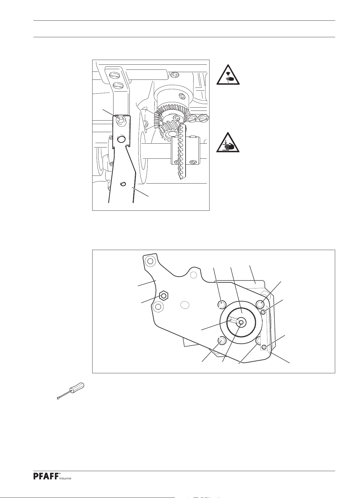
12.05 Lubricating the bevel gears .................................................................................................. 88
12.06 Topping up the thread lubrication oil reservoir ..................................................................... 89
12.07 Lubricating the roller presser drive gear mechanism (only at ø 25 mm and ø 35 mm) ........ 89
13 Table Top ............................................................................................................................. 90
13.01 Tilt base ............................................................................................................................... 90
13.02 Table top cutout ................................................................................................................... 91
14 Wearing Parts ..................................................................................................................... 92
Page 6

Safety
1 Safety
1
1.02 General safety instructions
.01 Directives
The machine was built in compliance with the European regulations specifi ed in the declara-
tion of conformity and declaration of incorporation.
As a supplement to this instruction manual, please also observe the generally applicable, le-
gal and other regulations and legislation – also in the country of use – and the valid environ-
mental protection regulations! Always comply with the locally applicable regulations of the
professional associations and other supervisory authorities!
The machine may only be operated after you have become acquainted with the
associated instruction manual and only by operating personnel who have received
appropriate training!
Always read the safety instructions and the instruction manual of the motor manufacturer
before starting up the machine!
Always follow the hazard and safety instructions attached to the machine!
The machine may only be operated for its intended purpose and only with the associated
safety covers, while adhering to all the relevant safety requirements.
The machine must always be disconnected from the power supply by pressing the main
switch or pulling out the mains plug when sewing tools are replaced (such as the needle,
sewing foot, needle plate and bobbin) and when threading, leaving the workstation, or
performing maintenance!
The daily maintenance work may only be carried out by suitably qualifi ed personnel!
Repairs and special maintenance work may only be carried out by technical staff or
people with appropriate training!
Work on electrical equipment may only be carried out by qualifi ed technical staff!
Work on parts and equipment under voltage is not permitted!
Exceptions are regulated by the EN 50110 standards.
Modifi cations and changes to the machine may only be made in compliance with all of
the relevant safety requirements!
Only the replacement parts approved by us for usage may be used for repairs! We warn
you expressly that spare parts and accessories that are not supplied by us are also not
tested and approved by us.
Fitting or using these products may therefore have negative effects on features which
depend on the machine design. We are not liable for any damage caused by the use of
non-Pfaff parts.
6
Page 7
Safety
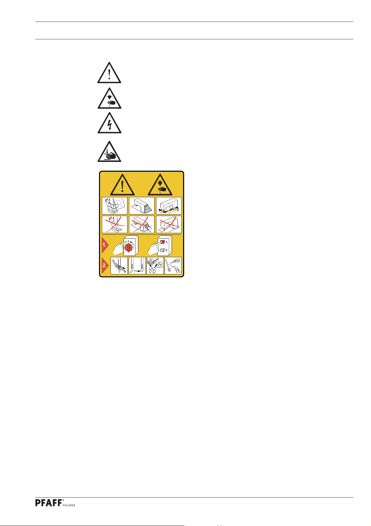
1.03 Safety symbols
Hazard point!
Special points of attention.
Risk of injury to operating personnel or technical staff!
Electric voltage!
Danger to operating personnel or technical staff
Danger of hands being crushed!
Danger to operating personnel or technical staff
Caution!
Do not operate without fi nger guard and safety covers!
Turn off the main switch before threading, changing the
bobbin or needle, cleaning, etc.!
I
1.04 Special points of attention for the owner-operator
This instruction manual is a part of the machine and must be made available to the oper-
ating personnel at all times. The instruction manual must have been read before the initial
start-up.
The operating personnel and technical staff must be instructed about the machine's safe-
ty covers and about safe working methods.
The owner-operator may only operate the machine in a fl awless condition.
The owner-operator must ensure that no safety covers are removed or disabled.
The owner-operator must ensure that only authorised persons work on the machine.
Additional information can be requested from the responsible sales centre.
7
Page 8

Safety
1.05 Operating personnel and technical staff
1
.05.01 Operating personnel
Operating personnel are persons responsible for equipping, operating and cleaning the
machine and for fault clearance in the sewing area.
The operating personnel are obligated to comply with the following points:
The safety instructions provided in the instruction manual must be followed for all work!
Any work method jeopardising machine safety must be refrained from!
Tight-fi tting clothing must be worn. The wearing of jewellery such as chains and rings is
prohibited!
Care must be taken to ensure that no unauthorised persons are located in the machine's
hazard zone!
Any changes occurring on the machine which impair its safety must be reported to the
owner-operator immediately!
1.05.02 Technical staff
Technical staff are persons with technical training in electricity/electronics and mechanics.
They are responsible for lubricating, servicing, repairing and adjusting the machine.
The technical staff are obligated to comply with the following points:
The safety instructions provided in the instruction manual must be followed for all work!
Turn off the main switch and secure it against reactivation before starting any adjustment
and repair work!
Never work on live parts and equipment!
Exceptions are regulated by the EN 50110 standards.
Reattach the safety covers following repair and maintenance work!
8
Page 9
Safety
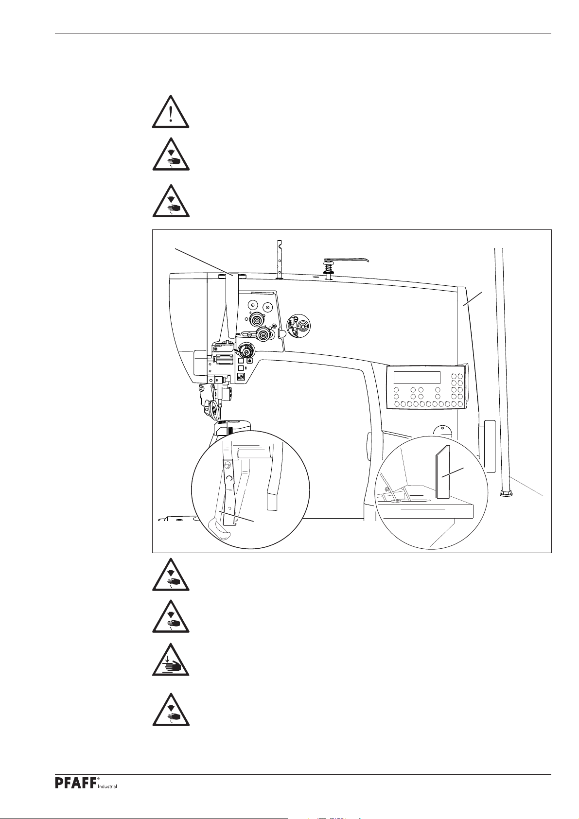
1.06 Danger warnings
A work area of 1 m must be kept free in front of and behind the machine to
ensure unobstructed access at all times.
Do not reach into the needle range during the sewing operation!
Risk of injury from the needle!
Do not allow any objects to be placed on the table during the adjustment work!
The objects could become jammed or be slung away!
Risk of injury from parts fl ying around!
1
2
Fig. 1 - 01
4
4
3
Do not operate the machine without the take-up lever guard 1!
Risk of injury due to the motion of the take-up lever!
Do not operate the machine without the belt guard 2!
Risk of injury due to the rotating driving belt!
Do not operate the machine without the anti-tipping device 3!
Risk of injury by crushing between the sewing head and the table top!
Do not operate the machine without the support 4! Risk of damage due to the
top-heavy sewing head!
Machine can tip over backwards when moving it!
9
Page 10

Proper Use
2 Proper Use
The PFAFF 1571 is a single needle post-bed high-speed seamer (post is positioned to the
left of the needle) with forwards- and backwards-moving feed wheel and roller presser plus
feed-synchronised needle.
The PFAFF 1574 is a two-needle post-bed high-speed seamer with forwards- and
backwards-moving feed wheel and roller presser.
The PFAFF 1591 is a single needle post-bed high-speed seamer (post is positioned to the
right of the needle) with forwards- and backwards-moving feed wheel and roller presser plus
feed-synchronised needle.
The PFAFF 1593 is a single needle post-bed high-speed seamer (post is positioned to the
right of the needle) with forwards- and backwards-moving feed wheel and roller presser.
The machines are used to create double lock stitch seams in the leather and upholstery
industries.
Any usage not approved by the manufacturer is deemed misuse!
The manufacturer shall assume no liability for damage caused by misuse!
Proper use also includes compliance with the operating, maintenance,
adjustment and repair measures specifi ed by the manufacturer!
10
Page 11

Technical Data
3 Technical Data
3
.01 PFAFF 1571
Stitch type: .........................................................................................................301 (lockstitch)
Needle system: .................................................................................................................... 134
Model BN7: ...................................................... for the machining of medium-weight materials
Model CN7: ........................................................for the machining of medium-heavy materials
Needle size in 1/100 mm:
Model BN7: ................................................................................................................... 90 - 110
Model CN7: ................................................................................................................. 120 - 150
Stitch length max: ..........................................................................................................7.0 mm
Speed max.:
Model BN7 ................................................................................................. 3500 stitches/min
Model CN7 ................................................................................................. 2000 stitches/min
Trimming margin (for -725/..) .................................................................................0.8 - 2.5 mm
Cutting speed (for -725/..) .................................................................................. 2800 cuts/min.
Clearance beneath the roller presser for dia. 30 mm: ......................................................7 mm
Clearance beneath the roller presser for dia. 25 mm and dia. 35 mm: ...........................12 mm
Passage width: .............................................................................................................245 mm
Clearance height: ..........................................................................................................115 mm
Post height ....................................................................................................................180 mm
Bed plate dimensions: ............................................................................................... 518 x 177
Sewing head dimensions
Length: ............................................................................................................. approx. 562 mm
Width: .............................................................................................................. approx. 250 mm
Height (above table): ........................................................................................ approx. 505 mm
Motor data: ..................................................................................see motor specifi cation plate
Noise data
(Noise measurement in accordance with DIN 45 635-48-A-1,ISO 11204, ISO 3744, ISO 4871)
Model B:
Emissions sound pressure level in the workplace at n = 2800 min-1: ............... LpA = 80 dB(A)
Model C:
-1
Emissions sound pressure level in the workplace at n = 1600 min
: .............. LpA = 74 dB(A )
Net weight of sewing head: ................................................................................ approx. 64 kg
Gross weight of sewing head: ............................................................................. approx. 74 kg
Subject to alterations.
Depending on the material, workstep and stitch length.
KpA = 2,5 dB
11
Page 12

Technical Data
3.02 PFAFF 1574
Stitch type: .........................................................................................................301 (lockstitch)
Needle system: ............................................................................................................... 134-35
Model BN5: ...................................................... for the machining of medium-weight materials
Model CN5: ........................................................for the machining of medium-heavy materials
Needle size in 1/100 mm:
Model BN5: ................................................................................................................... 90 - 110
Model CN5: ................................................................................................................. 120 - 150
Stitch length max: ..........................................................................................................5.0 mm
Speed max.:
Model BN5 ................................................................................................. 3000 stitches/min
Model CN5 ................................................................................................. 2000 stitches/min
Trimming margin (for -725/..) .................................................................................0.8 - 2.5 mm
Cutting speed (for -725/..) .................................................................................. 2800 cuts/min.
Clearance beneath the roller presser for dia. 30 mm: ......................................................7 mm
Clearance beneath the roller presser for dia. 25 mm and dia. 35 mm: ...........................12 mm
Passage width: .............................................................................................................245 mm
Clearance height: ..........................................................................................................115 mm
Post height ....................................................................................................................180 mm
Bed plate dimensions: ............................................................................................... 518 x 177
Sewing head dimensions
Length: ............................................................................................................. approx. 562 mm
Width: .............................................................................................................. approx. 250 mm
Height (above table): ........................................................................................ approx. 505 mm
Motor data: ..................................................................................see motor specifi cation plate
Noise data
(Noise measurement in accordance with DIN 45 635-48-A-1,ISO 11204, ISO 3744, ISO 4871)
Model B:
Emissions sound pressure level in the workplace at n = 2800 min-1: ............... LpA = 81 dB(A)
Model C:
-1
Emissions sound pressure level in the workplace at n = 1600 min
: .............. LpA = 74 dB(A )
12
Net weight of sewing head: ................................................................................ approx. 68 kg
Gross weight of sewing head: ............................................................................. approx. 78 kg
Subject to alterations.
Depending on the material, workstep and stitch length.
KpA = 2,5 dB
Page 13

Technical Data
3.03 PFAFF 1591
Stitch type: .........................................................................................................301 (lockstitch)
Needle system: .................................................................................................................... 134
Model BN7: ...................................................... for the machining of medium-weight materials
Model CN7: ........................................................for the machining of medium-heavy materials
Needle size in 1/100 mm:
Model BN7: .................................................................................................................... 90 -110
Model CN7: ................................................................................................................. 120 - 150
Stitch length max ...........................................................................................................7.0 mm
Speed max.:
Model BN7 ................................................................................................. 3500 stitches/min
Model CN7 ................................................................................................. 2000 stitches/min
Trimming margin (for -725/..) .................................................................................0.8 - 2.5 mm
Cutting speed (for -725/..) .................................................................................. 2800 cuts/min.
Clearance beneath the roller presser for dia. 30 mm: ......................................................7 mm
Clearance beneath the roller presser for dia. 25 mm and dia. 35 mm: ...........................12 mm
Passage width: .............................................................................................................245 mm
Clearance height: ..........................................................................................................115 mm
Post height ....................................................................................................................180 mm
Bed plate dimensions: ............................................................................................... 518 x 177
Sewing head dimensions
Length: ............................................................................................................. approx. 562 mm
Width: .............................................................................................................. approx. 250 mm
Height (above table): ........................................................................................ approx. 505 mm
Motor data: ..................................................................................see motor specifi cation plate
Noise data
(Noise measurement in accordance with DIN 45 635-48-A-1,ISO 11204, ISO 3744, ISO 4871)
Model B:
Emissions sound pressure level in the workplace at n = 2800 min-1: ............... LpA = 80 dB(A)
Model C:
Emissions sound pressure level in the workplace at n = 1600 min-1: .............. LpA = 74 dB(A )
Net weight of sewing head: ................................................................................ approx. 64 kg
Gross weight of sewing head: ............................................................................. approx. 74 kg
Subject to alterations.
Depending on the material, workstep and stitch length.
KpA = 2,5 dB
13
Page 14

Technical Data
3.04 PFAFF 1593
Stitch type: .........................................................................................................301 (lockstitch)
Needle system: .................................................................................................................... 134
Model BN5: ...................................................... for the machining of medium-weight materials
Needle size in 1/100 mm:
Model BN5: .................................................................................................................... 90 -110
Stitch length max ...........................................................................................................5.0 mm
Speed max.:
Model BN5 ................................................................................................. 3500 stitches/min
Clearance beneath the roller presser for dia. 30 mm: ......................................................7 mm
Clearance beneath the roller presser for dia. 25 mm and dia. 35 mm: ...........................12 mm
Passage width: .............................................................................................................245 mm
Clearance height: ..........................................................................................................115 mm
Post height ....................................................................................................................180 mm
Bed plate dimensions: ............................................................................................... 518 x 177
Sewing head dimensions
Length: ............................................................................................................. approx. 562 mm
Width: .............................................................................................................. approx. 250 mm
Height (above table): ........................................................................................ approx. 505 mm
Motor data: ..................................................................................see motor specifi cation plate
Noise data
(Noise measurement in accordance with DIN 45 635-48-A-1,ISO 11204, ISO 3744, ISO 4871)
Emissions sound pressure level in the workplace at n = 2800 min-1: ..............LpA = 80 dB(A))
Net weight of sewing head: ................................................................................ approx. 64 kg
Gross weight of sewing head: ............................................................................. approx. 74 kg
Subject to alterations.
Depending on the material, workstep and stitch length.
KpA = 2,5 dB
14
Page 15

Disposal of the Machine
4 Disposal of the Machine
It is up to the customer to dispose of the machine properly.
The materials used for the machine include steel, aluminium, brass and various plastics.
The electrical equipment consists of plastics and copper.
The machine must be disposed of in accordance with the locally valid environmental
protection regulations, with a specialised company being contracted if necessary.
Please ensure that parts coated with lubricants are disposed of separately in
accordance with the locally valid environmental protection regulations!
15
Page 16

Transport, Packaging and Storage
5 Transport, Packaging and Storage
5
.01 Transport to the customer's premises
All machines are completely packed for delivery.
5.02 Transport within the customer's premises
The manufacturer assumes no liability for transport within the customer's premises or to
the individual usage sites. Please ensure that the machines are only transported in a vertical
position.
5.03 Disposal of the packaging materials
The packaging materials of these machines consists of paper, cardboard and VCI fl eece. It is
up to the customer to dispose of the packaging properly.
5.04 Storage
The machine can be stored for up to 6 months when not in use. It must then be protected
from dirt and moisture. For longer storage periods, the machine's single components,
especially its sliding surfaces, must be protected against corrosion, e.g. by an oil fi lm.
16
Page 17

Work Symbols
6 Work Symbols
Activities to be performed or important information in this instruction manual are
emphasised by symbols. The symbols used have the following meaning:
Note, information
Cleaning, care
Lubrication
Maintenance, repairs, adjustment, service work
(only to be carried out by technical staff)
17
Page 18
Operating Controls
7 Operating Controls
7
.01 Main switch
Before switching on the machine, raise the take-up lever as far as possible.
Turning the main switch 1 switches the ma-
chine on and off.
1
Fig. 7 - 01
7.02 Keys on the machine head
The machine sews backwards as long as
the key 1 is pressed during the sewing
operation.
The keys 2 can be assigned functions us-
ing parameters “203” and “204”. (See
chapter 15.07 Parameter settings).
The sewing lamp integrated on the ma-
chine head is switched on and off with
3
the key 3.
2
18
1
Fig. 7 - 02
Page 19

Operating Controls
7.03 Bobbin thread monitoring using the stitch count
The diode 1 fl ashes on reaching the
predefi ned stitch count.
The stitch count re-starts after trimming
the thread and changing the bobbin.
For presetting the stitch count
please refer to chapter 9.11 Set-
ting the bobbin stitch counter.
1
Fig. 7 - 03
7.04 Pedal
With the main switch turned on
0 = Neutral position
0
+1
+ 1 = Sewing
- 1 = Raise roller presser
- 2 = Trim thread
Other pedal functions can be
set through the programming,
see chapter 10 Sewing.
-1
Fig. 7 - 04
-2
19
Page 20
Operating Controls
7.05 Hand lever to raise the roller presser
Turning the hand lever 1 raises the roller
presser.
Fig. 7 - 05
7.06 Swivelling out the roller presser
The roller presser 1 can be swivelled out
by gently pulling downwards when the
roller presser is in the raised position.
20
Fig. 7 - 06
Page 21
Operating Controls
7.07 Knee switch
It is possible to choose between 2
predefi ned fullnesses or 2 stitch lengths
in manual sewing by pressing the knee
switch 1.
It is possible to move to the next seam
zones in programmed sewing by using
the knee switch 1.
The function of the knee
switch 1 must be activated on
the control panel, see chapter
10 Sewing.
Fig. 7 - 07
7.08 Knee lever
1
Pressing the knee lever 1 in the direction
shown by the arrow raises the roller
presser.
Fig. 7 - 08
21
Page 22
Operating Controls
7.09 Edge trimmer -725/04 for PFAFF 1571
Fig. 7 - 09
3
4
2
6
5
1
Switching on the knife drive:
Swivel the lever 1 backwards; the knife
moves to the operating position.
Switching off the knife drive:
Press the lever 1; the knife swivels away
backwards.
Switching on the edge guide:
Swing in the edge guide 2 by hand and
press the lever 3; the edge guide 2
moves to the operating position.
Switching off the edge guide:
Raise the edge guide 2 and allow it
to engage; the edge guide 2 is out of
operation.
Raise the lever 4; the edge guide swivels
away backwards.
Do not reach into the knife
during operation! Risk of injury!
Replacing knives:
The work described below may only be carried out by technical staff or people
with appropriate training!
Switch the machine off.
Release the screw 5 and remove the knife 6.
Insert a new knife and gently tighten the screw 5.
Adjust the knife as described in chapter 15.05.05 Knife movement of the adjustment
manual and tighten the screw 5.
22
Page 23

Operating Controls
7.10 Edge trimmer -725/04 for PFAFF 1574 and 1591
3
4
2
7
6
5
1
Fig. 7 - 10
Do not reach into the knife during operation! Risk of injury!
Switching on the knife drive:
Swivel the lever 1 backwards; the knife moves to the operating position.
Switching off the knife drive:
Press the lever 1; the knife swivels away backwards.
Switching on the edge guide:
Swing in the edge guide 2 by hand and press the lever 3; the edge guide 2 moves to the
operating position.
Switching off the edge guide:
Raise the edge guide 2 and allow it to engage; the edge guide 2 is out of operation.
Raise the lever 4; the edge guide swivels away backwards.
Replacing knives:
The work described below may only be carried out by technical staff or people
with appropriate training!
Switch the machine off.
Release the screw 5 and remove the knife 6.
Insert a new knife and slide it fully towards the needle plate insert 7.
Gently tighten the screw 5.
Adjust the knife as described in chapter 15.05.07 Knife position of the adjustment
manual and tighten the screw 5.
23
Page 24

Operating Controls
7.11 Control panel
Machine functions for set-up and sewing, to enter parameters and service settings are
displayed and called up via the control panel.
1
Fig. 7 - 11
3
2
The control panel consists of the following operating and display controls:
The display 1 comprises a two-line alphanumeric LCD display with 16 characters per
line and is used to display relevant information and the selection of parameters.
The +/- keys 2 are used to select or change the functions and parameters displayed.
The function keys 3 are used to switch the relevant function on or off. Switched-on
functions are each indicated by an illuminated LED lamp.
7.11.01 What appears on the display
Besides the texts and setting values, the following symbols are shown on the display.
The symbols appear solely in programmed sewing mode, see chapter 10.02 Programmed
sewing.
.
Current program number
P
Current seam section
Seam input via "teach-in"
T
DEL
Deleting a program
Stitch count in the current seam zone
24
Maximum speed in the current seam zone
Stitch length (feed motion) for the roller presser
Stitch length (feed motion) for the feed wheel
Page 25

Operating Controls
7.11.02 +/- keys
A B C D
3 3 3 3
Setting values (e.g. input of backtack stitches) are selected and changed using the
respective +/- keys. Pressing and holding the corresponding +/- key will slowly change the
number value shown above the key. The change to the number value will be made quicker if
the +/- key is held for a longer period of time.
7.11.03 Function keys
An active function is always indicated by a corresponding illuminated LED lamp.
Detailed functional description: Start backtack
Start backtack
The seam lock at seam start (start backtack) is turned on or off by pressing this key. The
number of start backtack forward stitches (A) or backward stitches (B) can be changed
in manual sewing by pressing the respective key underneath. Reset the corresponding
partial seam stitch count to zero to convert from double backtack to single backtack.
End backtack
The seam lock at seam end (end backtack) is turned on or off by pressing this key.
The number of start reverse stitches (C) or forward stitches (D) can be changed in
manual sewing by pressing the respective +/- key underneath. Reset the corresponding
partial seam stitch count to zero to convert from double backtack to single backtack.
Needle position up after sewing stop
The “needle position up after sewing stop” function is turned on or off by pressing this
key. If this function is on, the needle moves to top dead centre when sewing stops.
Foot position after stop
The "foot position up after sewing stop" function is turned on or off by pressing this key.
If this function is on, the sewing foot is raised when sewing stops.
Foot position after thread trimming
The "foot position up after thread trimming" function is turned on or off by pressing this
key. If this function is on, the sewing foot is raised after the thread has been trimmed.
Thread trimming
The "thread trimming" function is switched on or off by pressing this key.
25
Page 26

Operating Controls
Speed
With this key, a maximum speed for each seam zone can be defi ned which is only
activated in the corresponding seam zone.
Reverse sewing (only for programmed sewing)
If this key is pressed, the reverse sewing function is switched on or off.
Program interrupt
The automatic processing of a sewing program is interrupted by pressing this key.
The stitch count is switched off and a few processes vary.
Stop
The machine stops automatically at the seam zone end in programmed sewing when the
function is turned on.
Photo cell
The corresponding function is switched on and off by pressing this key. If this function is
on, the machine moves to the next seam zone via the photo cell.
Stitch count (only for programmed sewing)
The corresponding function is switched on and off by pressing this key. If this function
is on, the machine moves to the next seam zone after sewing the number of stitches
entered.
TE/speed
If this key is pressed once, the speed limit for the programmed sewing mode is
activated.
If this key is pressed twice (within 5 seconds) the machine changes from sewing mode
to input mode.
Scroll
If this key is pressed, the input menus on the display are scrolled through.
PM / mode
If this key is pressed, the programmed sewing function is switched on or off.
The program-specifi c parameters are shown in the alphanumeric part of the display.
F1
If this key is pressed, the placed stitch position is switched on or off when sewing begins.
The corresponding needle position is set using the key and by turning the handwheel.
F2
No function is assigned.
F3
The corresponding function is switched on and off by pressing this key. If this function
is on, the machine moves to the next seam zone by using the knee switch.
26
F4
If this key is pressed, the next backtack is not stitched. If this key is pressed twice,
the next two backtacks are not stitched.
Page 27
Set-up and Initial Commissioning
8 Set-up and Initial Commissioning
The machine may only be set up and started up by qualifi ed personnel! All of
the relevant safety regulations must always be complied with in this process!
If the machine was delivered without a table, then the stand and the table top
provided must safely support the weight of the machine and its motor.
Adequate stability of the stand must be guaranteed, even during the sewing
operations.
8.01 Set-up
Suitable electrical supply connections must be provided at the erection site, see chapter 3
Technical Data. The erection site must also have a fi rm and level subsurface and adequate
lighting.
The table top is lowered for packaging purposes.
The adjustment of the table height is described below.
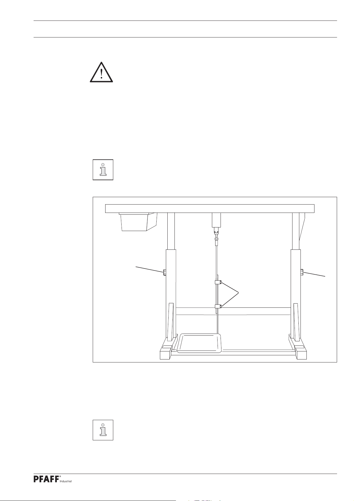
8.01.01 Setting the table height
1
2
Fig. 8 - 01
The stand must have all four feet fi rmly on the ground to make sure it is positioned
securely.
Loosen the screws 1 and 2.
Move the table top to the desired working height by pulling it out and pushing it in and
align the table top horizontally.
Adjust the stand on both sides evenly to prevent it tilting.
1
Firmly tighten the screws 1.
Adjust and tighten the desired pedal position on the screws 2.
27
Page 28
Set-up and Initial Commissioning
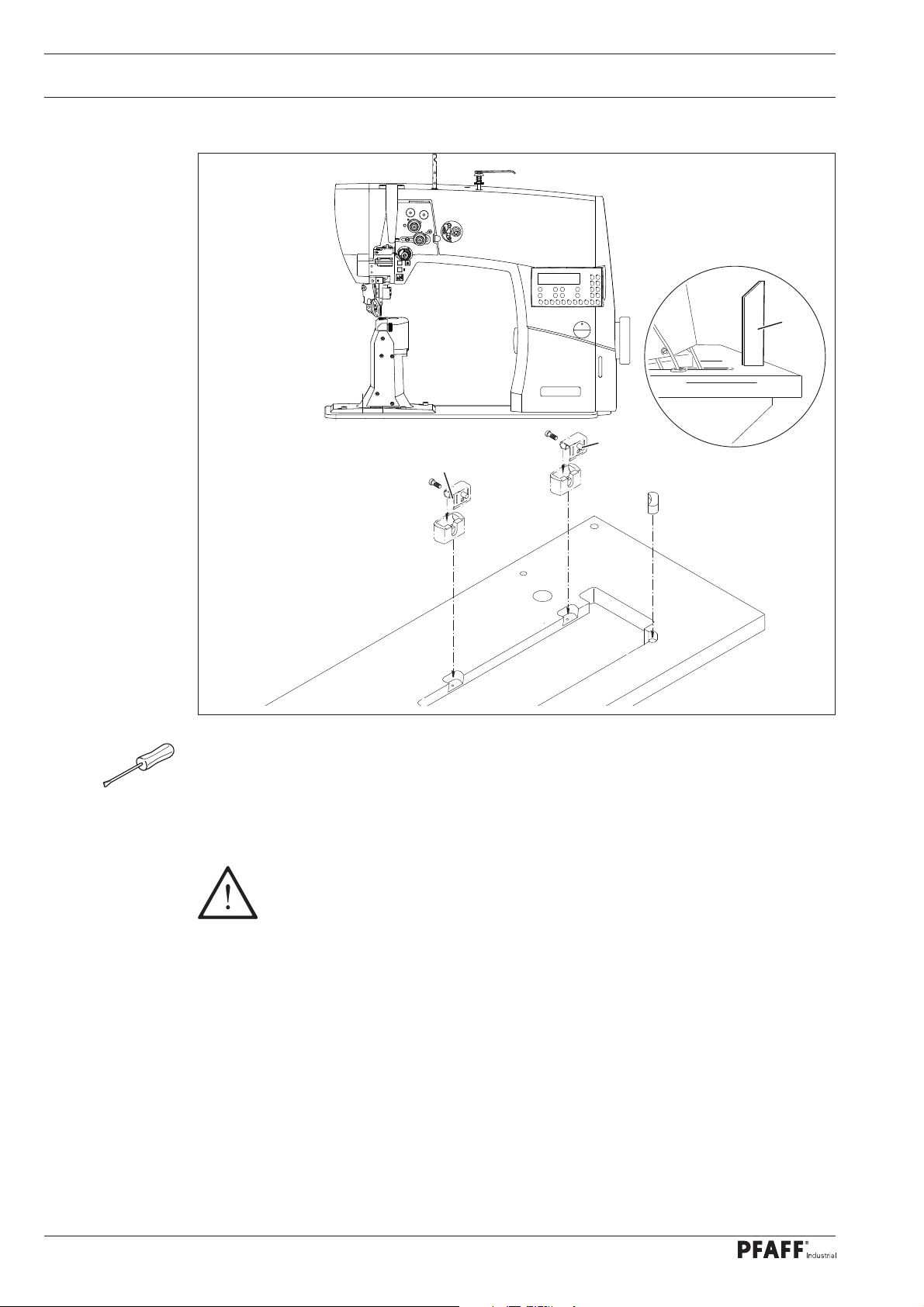
8.01.02 Inserting the sewing machine into the stand
2
4
1
1
Fig. 8 - 02
The hinges 1 are screwed to the sewing head base plate.
Insert the sewing machine into the table top.
Insert the sewing head support 2 into the table top hole.
Do not operate the machine without the support 2! Risk of damage due to the
top-heavy sewing head!
Machine can tip over backwards when moving it!
28
Page 29
Set-up and Initial Commissioning
.01.03 Assembling the anti-tipping device
8
2
1
Fig. 8 - 03
Switch off the machine!
Risk of injury due to accidental
machine start-up!
Screw on the anti-tipping device 1 includ-
ed in the accessories with the screw 2.
Do not operate the machine
without the anti-tipping device 1!
Risk of injury by crushing
between the sewing head and
the table top!
8.02 Mounting the fl ange motor
8
.02.01 Mounting the fl ange motor on the bearing plate
3
1
9
8
Fig. 8 - 04
Fix the bearing plate 1 onto the motor 2 using the screws 3, as shown in fi g. 8-04.
Remove the wedge from the motor shaft 4.
3
4
7
2
3
6
6
3
5
Attach the angle bracket 5 with the screws 6.
Mount the toothed belt wheel 7 onto the motor shaft 4 so that the screw 8 is positioned
with the lug in the motor shaft slot 4.
Screw the threaded pins 9 into the bearing plate 1.
29
Page 30

Set-up and Initial Commissioning
8.02.02 Mounting the fl ange motor on the machine
2
Use the screw 3 and 4 to fi x the bearing
plate 1 of the motor 2 to the machine
housing (tighten the screws 3 and 4
slightly).
4
1
Fig. 8 - 05
3
8.02.03 Mounting the machine cover
2
1
4
Use the screws 2 (2x) and the screws 4
(3x) to fasten the cover 1 to the housing.
Place the cover 3 on the cover 1 and
fasten with the screws 4 (3x).
3
4
30
Fig. 8 - 06
Page 31

Set-up and Initial Commissioning
8.02.04 Connecting the plug-in connections and ground cable
B
4
1
0
3
4
D
C
D
B
A
2
E
M
Fig. 8 - 07
Insert all connectors on the control box 2 in accordance with their designation.
Caution
Inserting the connector incorrectly can damage the control unit!
Attach the following ground cables in order to discharge static electricity
Securely attach the ground cable from the sewing head 1 to ground point A.
Securely attach the ground cable from the control point B to ground point B.
Securely attach the ground cable from the main switch 3 to ground point C.
Securely attach the ground cable from the stand 4 to ground point D.
Securely attach the ground cable from the motor cable M to ground point E.
31
Page 32

Set-up and Initial Commissioning
8.02.05 Fitting the toothed belt / home position of the machine drive with the
PFAFF 1571; 1591 and 1593
Switch the machine on
2.5 2.5
2 x
No
Press the TE/Speed key twice to call up the input mode.
NO VAL
101 II
Select the parameter group “600” by pressing the corresponding +/- key.
NO
600
Confi rm the selection by pressing the corresponding +/- key.
Enter the template code, see chapter 9.10 Entering/changing the template code.
32
NO
603 8
Select the parameter group “603” by pressing the corresponding +/- key.
Turn the motor shaft by hand until the display shows the value "8”.
Turn the handwheel in the direction of rotation until the needle point (approaching from
above) is on the upper edge of the needle plate.
Lay on the toothed belt 1 while making sure that both the motor shaft 4 (Fig. 8 - 08) and
the machine are not twisted.
Page 33

Set-up and Initial Commissioning
3
3
Fig. 8 - 08
Fit the toothed belt 1
Pivot the motor bearing plate 2 so that the toothed belt 1 is taut.
Tighten the screws 3 in this position.
Turn the handwheel in the direction of rotation until the needle point (approaching
from above) is on the upper edge of the needle plate. ± 2 increments are permitted as
a tolerance.
Complete the adjustment of the sewing motor by pressing the TE/SPEED key.
1
2
4
33
Page 34

Set-up and Initial Commissioning
8.02.06 Fitting the toothed belt / home position of the machine drive with the
PFAFF 1574
Fit the toothed belt 1 (Fig. 8 - 08).
Pivot the motor bearing plate 2 so that the toothed belt 1 is taut.
Tighten the screws 3 in this position.
10
9
8
Slide the synchroniser 8 onto the shaft so
that the position fi nger 9 is positioned in
the synchroniser groove (see arrow).
Gently tighten the screws 10.
Plug the adapter cable 11 into the
bushing X 3 on the control unit.
Connect the synchroniser 12 to connector
S.
Connect the motor to connector R.
Connect the ground cable 13 to the
housing.
Fig. 8 - 09
11
13
X8
12
X3
S
R
34
Fig. 8 - 10
Page 35

Switch the machine on
Set-up and Initial Commissioning
2 x
No
2.5 2.5
Press the TE/Speed key twice to call up the input mode.
NO VAL
101 II
Select the parameter group “600” by pressing the corresponding +/- key.
NO
600
Confi rm the selection by pressing the corresponding +/- key.
Enter the template code, see chapter 9.10 Entering/changing the template code.
NO
603
Select the parameter group “603” by pressing the corresponding +/- key.
NO
603
Turn the machine one revolution by pressing the corresponding +/- key.
Check the needle bar position.
Loosen the synchroniser screws 10, hold the synchroniser shaft tightly and turn the hand-
wheel in the direction of rotation until the needle point (approaching from above) is on
the upper edge of the needle plate.
Tighten the synchroniser screws.
Turn the machine one revolution again by pressing the corresponding +/- key again and check the
setting - repeat the setting process if necessary.
Complete the adjustment of the sewing motor by pressing the TE/Speed key.
35
Page 36

Set-up and Initial Commissioning
8.02.07 Mounting the fl ange motor belt guard
1
Attach the belt guard 1 with the screws
2 and 3.
2
3
Fig. 8 - 11
8.02.08 Connecting the safety switch
2
Plug in the connector 1 of the safety
switch 2 as shown in Fig. 8 - 12.
If the sewing head is tilted
back, the safety switch
activates the start inhibitor,
preventing the machine starting
up if the main switch is turned
on.
36
1
Fig. 8 - 12
Page 37

Set-up and Initial Commissioning
8.02.09 Checking the start inhibitor function
STOP
2.5 2.5
Switch on the machine at the main switch and move the sewing head.
The error message “STOP” must appear on the control panel.
If this message does not appear, check the switch 2 setting.
The machine is ready for operation again after righting the sewing head.
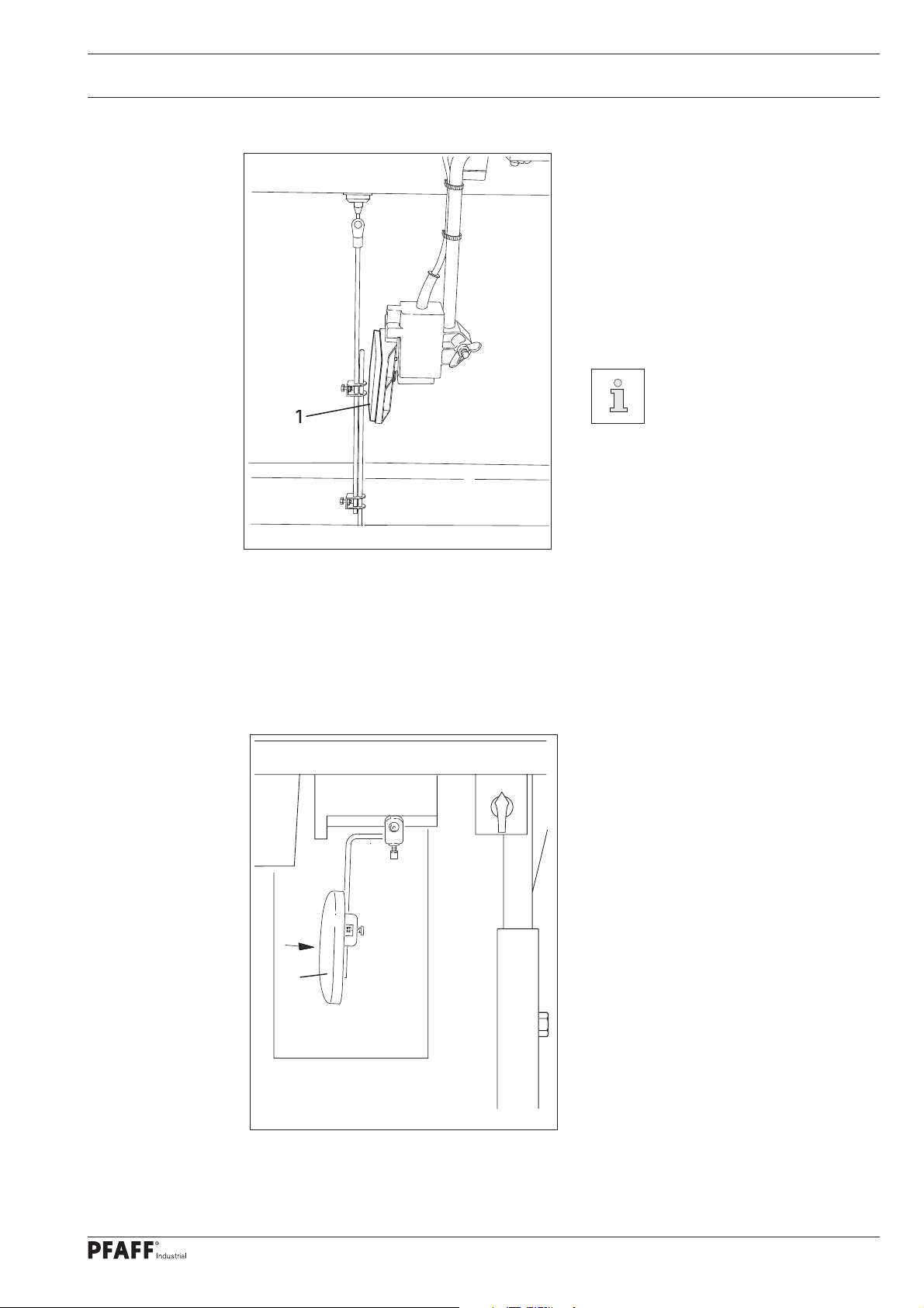
8.03 Assembling the reel stand
Fig. 8 - 13
Assemble the reel stand as shown in the
adjacent illustration.
Then insert the stand into the hole in the
table top and secure it with the enclosed
nuts.
37
Page 38

Set-up and Initial Commissioning
8.04 Initial start-up
Inspect the machine for any damage, particularly the electric cables.
Clean the machine thoroughly and then oil it, see also chapter 12 Maintenance and
Care.
Arrange for technical staff to check whether the machine's motor may be operated at the
existing mains voltage and whether it is connected properly.
Never operate the machine if there are any differences.
The machine must only be connected to a grounded socket!
Arrange for the home position of the machine drive to be verifi ed by certifi ed
technicians before the initial start-up! Have these settings carried out where
required.
8.05 Switching the machine on / off
Switch the machine on (see chapter 7.01 Main switch).
38
Page 39

Set-up
9 Set-up
Observe and comply with all regulations and instructions in this instruction
manual.
Pay particular attention to all safety regulations!
All set-up work may only be carried out by appropriately instructed personnel.
Disconnect the machine from the electricity mains for all set-up work by operat-
ing the main switch or by removing the mains plug!
9.01 Inserting the needle
1
3
Fig. 9 - 01
Switch off the machine!
Risk of injury due to accidental machine start-up!
Only use needles of the system intended for the machine, see chapter 3
Technical Data!
PFAFF 1571; 1591 and 1593
Raise and fold out the roller presser 3
1
1
2
2
3
Fig. 9 - 02
PFAFF 1574
Raise and fold out the roller presser 3
Bring the needle bar to the top posi-
tion.
Loosen the screw 1 and insert the
needle 2 until you feel it stop. The
long groove must point to the right
with the PFAFF 1571 and to the left
with the PFAFF 1591 and 1593.
Tighten the screw 1.
Bring the needle bar to the top position.
Loosen the screws 1 and insert the nee-
dles 2 until you feel them stop. The long
groove of the left needle must point to
the right and that of the right needle
must point to the left.
Tighten the screws 1.
39
Page 40

Set-up
9.02 Winding the bobbin thread, adjusting the thread tension
7
4
1
6
5
3
9
2
8
Fig. 9 -03
Fit the empty bobbin 1 onto the bobbin winder spindle 2 with the rest thread chamber on
the outside.
Thread in the thread as shown in Fig. 9 - 03 and wind it round the bobbin 1 a few times in
an anti-clockwise direction.
Switch on the bobbin winder by pressing the bobbin winder spindle 2 and the lever 3
simultaneously.
40
The bobbin fi lls up during sewing.
If the machine is only run for bobbin winding (without sewing), a bobbin case
must be fi tted in the hook!
Otherwise a jammed thread may damage the hook!
The tension of the thread on the bobbin 1 can be adjusted with the knurled thumb screw 4.
The bobbin winder stops automatically when the bobbin 1 is suffi ciently full.
Remove the fi lled bobbin 1 and cut the thread with the knife 5.
The fi ll amount of the bobbin 1 can be adjusted with the pin 8 (loosen the screw 9 and
tighten it again) if the thread is wound unevenly:
Loosen the nut 6.
Turn the thread guide 7 accordingly.
Tighten the nut 6.
Page 41

Set-up
9.03 Removing / inserting the bobbin case
Fig. 9 -04
1
2
Removing the bobbin case:
Bring the take-up lever to its top position
Open the post cover, raise the lever 1
and remove the bobbin case 2.
Inserting the bobbin case:
Press the bobbin case 2 until you feel it
snap into the bobbin case base.
Move the lever 1 and close the post cov-
er.
Do not operate the machine with an open post cover!
Risk of injury due to moving parts!
Switch off the machine!
Risk of injury due to accidental
machine start-up!
9.04 Inserting the bobbin case / adjusting the bobbin thread tension
Switch off the machine!
Risk of injury due to accidental
machine start-up!
1
5 cm
+
Insert the bobbin as shown in Fig. 9 - 05.
When the thread is drawn off, the bobbin
must turn in the direction shown by the
arrows.
Adjust the thread tension by turning the
screw 1.
-
Fig. 9 -05
41
Page 42

Set-up
9.05 Threading the needle thread / adjusting the needle thread tension
(with the PFAFF 1571; 1591 and 1593)
1
+
Fig. 9 - 06
-
Switch off the machine!
Risk of injury due to accidental machine start-up!
42
Thread the needle thread as shown in Fig. 9 - 06. Please ensure that the PFAFF 1571
needle is threaded from right to left and that of the PFAFF 1591;1593 is threaded from
left to right.
Adjust the needle thread tension by turning the knurled thumb screw 1.
Page 43

Set-up
9.06 Threading the needle thread / adjusting the needle thread tension
(with the PFAFF 1574)
2
1
+
Fig. 9 - 07
-
+
-
Switch off the machine!
Risk of injury due to accidental machine start-up!
Thread the needle thread as shown in Fig. 9 - 07. Please ensure that the right needle is
threaded from the left and the left needle is threaded from the right.
Adjust the needle thread tension by turning the knurled thumb screw 1 (right needle or 2
left needles).
43
Page 44

Set-up
9.07 Adjusting the stitch length
9.07.01 Entering the sealing speed
The stitch length is defi ned by setting the feed motion of the roller presser and feed wheel.
For the incorporation of fullness, the feed motion on the roller presser must be larger or
smaller than the feed motion on the feed wheel.
Switch the machine on.
Once the machine is switched on, the current stitch length values for the roller presser
and feed wheel are shown in the display.
2.5 2.5
Set the stitch length (feed motion) for the roller presser by pressing the
corresponding +/- key.
Set the stitch length (feed motion) for the feed wheel by pressing the corresponding
+/- key.
9.07.02 Entering a second stitch length or fullness
Using the PM key, a second stitch length or fullness setting can be made in addition to the
standard stitch length. Switching between both settings is carried out in programmed sew-
ing by pressing the knee switch.
2
1 1 2.5 2.5
Switch machine on.
Press the PM key to enter programmed sewing (LED lamp lights up).
Select the program number (1 or 2) by pressing the corresponding +/- key.
Sew 1 - 2 stitches and press the knee switch, see also chapter 7.07 Knee switch.
44
Set the stitch length (feed motion) for the roller presser by pressing the
corresponding +/- key.
Set the stitch length (feed motion) for the feed wheel by pressing the corresponding +/-
key.
Page 45

Set-up
9.08 Entering the start and end backtacks
Switch machine on.
2.5 2.5
Set the corresponding function by pressing the start backtack and/or the end backtack
keys. (LED lamp lights up)
Switch to the input menu for the start and end backtacks by pressing the scroll key.
A B C D
3 3 3 3
C
A
B
D
Select the desired value for the number of start backtack forward switches (A) by press-
ing the corresponding +/- key.
Select the desired value for the number of start backtack reverse stitches (B) by pressing
the corresponding +/- key.
Select the desired value for the number of end backtack reverse stitches (C) by pressing
the corresponding +/- key.
Select the desired value for the number of end backtack forward stitches (D) by pressing
the corresponding (+/- key.
The input menu for the stitch length is called up again by pressing the scroll key.
45
Page 46

Set-up
9.09 Entering/changing the template code
Switch machine on.
2.5 2.5
2 x
No
Press the TE/Speed key twice to call up the input mode.
NO VAL
101 II
Select the parameter group “800” by pressing the corresponding +/- key.
NO
800
Confi rm the selection by pressing the corresponding +/- key.
CODE: 1500
46
0
1
Enter the template code by pressing the corresponding keys (the factory setting is code
“1500”, see also chapter 7.11.03 Function keys.
Conclude the input of the template code by pressing the corresponding +/- key.
The code input remains saved until the machine is switched off by the
main switch. Provided that the machine is not turned off, all parameters
can be accessed without re-entering the template code.
5
Page 47

Set-up
NO VAL
801 0
No
Select the parameter “810” by pressing the corresponding +/- key.
810 1500
Confi rm the selection by pressing the corresponding +/- key.
CODE: 1500
0
2
1
3 4 5
6
7 8
9
Enter the template code by pressing the corresponding keys, see also chapter 7.11.03
Function keys.
End the input by pressing the TE/SPEED key. The newly entered template code is saved
and the sewing mode is called up.
Provided that the machine is not turned off, all parameters can be
accessed without having to repeatedly enter the template code. Do not
forget the code. Protected functions cannot be called up without the
corresponding code! Please contact PFAFF customer service centre in this
case.
47
Page 48

Set-up
9.10 Setting the bobbin stitch counter
Switch machine on.
2.5 2.5
2 x
No
VAL
Press the TE/Speed key twice to call up the input mode (LED lamp lights up).
NO VAL
101 II
Select the parameter group “105” by pressing the corresponding +/- key.
NO VAL
105 1000
Set the number of stitches that can be sewn with a bobbin by pressing the correspond-
ing +/- keys.
End the input by pressing the TE/Speed key. The entered value is saved and the sewing
mode is called up.
48
The stitch count function can only be activated when parameter “104” is
set to “1”.
Page 49

Set-up
9.11 Inserting and removing the SD memory card
Insert the SD card
1
Open the cover 1.
Insert the SD card 2 into the card slot
with the label facing forwards.
2
2 GB
max.
Close the cover 1 again.
Only use FAT 16 format
memory cards.
Remove the SD card
Open the cover 1.
3
Fig. 9 - 08
Adjusting the slide 3 makes it possible to activate ("LOCK" position) or
deactivate the write protection function on the SD memory card. The write
protection function must be deactivated to store, edit or delete data on
the SD memory card.
Press gently on the corner of the SD
memory card 2 - the SD card will be
ejected.
Close the cover 1 again.
The SD card must be kept for future boot processes.
The SD card is not a default confi guration.
49
Page 50

Sewing
10 Sewing
10.01 Manual sewing
In sewing mode all settings relevant for the sewing operation are shown in the display.
Functions can be switched on or off by pressing the key, values for start and end backtacks
or placed stitch can be altered directly.
A difference is made between manual sewing and programmed sewing in this mode.
The “PM” key is used to switch between manual sewing (LED lamp off) and programmed
sewing (LED lamp on).
Fixed programs are set under the program numbers 1-2. The program numbers 3-99 can be
assigned freely programmable seams.
After the machine has been switched on and manual sewing has been selected by pressing
the PM key, the display appears for entering the stitch length, see also chapter 9.07 Setting
the stitch length.
2.5 2.5
If the backtack function is switched on, the display appears for entering the backtack values,
see also chapter 9.08 Entering the start and end backtacks.
Pressing the scroll key switches between the displays.
A B C D
3 3 3 3
For other functions during manual sewing, see also chapter 7.11 .03 Function keys:
50
Backtack suppression Raise roller presser on/off
Start backtack on/off
End backtack on/off Thread trimming on/off
Raise needle position on/off
Sewing is carried out using the pedal function, see also chapter 7.04 Pedal.
Raise roller presser after seam end on/
off
Page 51

Sewing
10.02 Programmed sewing
In programmed sewing a difference is made between fi xed programs (program numbers 1
and 2) and freely programmable sewing programs (program numbers 3-99).
The fi xed programs are are used for the quick and easy production of seams with different
number of stitches or fullness. The respective 2 or 3 seam zones are switched using the
knee switch function, see also chapter 7.07 Knee switch.
The fi xed programs are also designed as running programs and can be concluded by the
pedal function, see also chapter 7.04 Pedal.
The freely programmable sewing programs (program numbers 3 to 99) can be entered,
altered or deleted if necessary, see chapter 11 Input.
After the machine has been switched on (chapter 7.01 Main switch) and the programmed
sewing mode key has been selected with the PM key, the display appears for selecting the
program number, seam zone and stitch length.
2
1 1 2.5 2.5
If other functions are switched on, for example backtack functions, maximum seam
zone speed or stitch count, the scroll key can be used to switch between other menu
displays, for example, for entering the values in the corresponding seam zone and stitch
count.
The number of backtack stitches is set in manual sewing mode, see chapter
9.08 Entering the start and end backtacks. The values entered apply to all
seam programs.
2
1 1 1300 134
Entering the values is carried out by pressing the corresponding +/- key.
51
Page 52

Sewing
For other functions in programmed sewing, see also chapter 7.11 .03 Function keys:
Place stitch position on/off Thread trimming on/off
Knee switch function on/off Seam zone speed on/off
Backtack suppression on/off Reverse sewing direction on/off
Start backtack on/off Program interrupt
End backtack on/off Programmed stop on/off
Raise needle position on/off Photo cell on/off
Raise roller presser on/off Stitch count on/off
Raise roller presser after
thread trimming on/off
Sewing is carried out using the pedal functions, see chapter 7.04 Pedal.
If multiple seam zones belong to a seam program, the individual seam zones
are automatically processed one after the other.
52
Page 53

Sewing
10.03 Program interrupt
If the course of a seam program is interrupted (e.g. a broken thread), the program interrupt
function must be called up.
The seam program course is interrupted after pressing the program interrupt key.
Sewing can continue manually and the values for the stitch length from the current seam
program are taken over.
2
5 1 2.5 2.5
The corresponding +/- key can be used to select the seam zone, in which the seam
program should be continued.
By pressing the program interrupt key again, the machine moves into the selected
seam zone and the programmed sewing function is continued.
10.04 Error messages
When a fault occurs, the display shows "ERROR" together with an error code, as shown
in the following example. In addition, the LED in the memory card slot lights up red
(see arrow). An error message can be caused by the incorrect set up, faulty elements or
overloading.
ERROR: 9
Correct the error.
Confi rm the error correction if required by pressing the TE/Speed key.
The LED in the memory card slot lights up yellow (see arrow).
For a description of errors see chapter 11 .07 Error codes and descriptions.
53
Page 54

Input
11 Input
This chapter describes the input mode functions and how to enter seam programs.
11 .01 Input mode
When the machine is in its initial state, it is possible to enter the parameters and the
corresponding values directly in the control unit. The functions information, photo cell and
service can be called up.
11.01.01 Overview of the functions in input mode
The input mode is called up by pressing the TE/Speed key twice.
2 x
A difference is made between parameter inputs and seam program inputs within the input
mode.
The PM key is used to enter into the seam program input after calling up the input mode.
11.01.02 Overview of the seam program input
Call up seam program input
Select program number (corresponding +/- key)
Select input variants
P
Seam program input/ alteration
Confi rm selection (Enter)
Seam zone
Stitch length (feed motion) roller presser
Stitch length (feed motion) feed wheel
Scroll (only when the following functions are turned on)
Seam zone
Max. speed
Stitch number
Placed stitch position
Scroll (only when the following functions are turned on)
Seam zone
Start backtack forward stitches
A
Start backtack backward stitches
B
Start backtack speed
54
Scroll (only when the following functions are turned on)
Seam zone
End backtack backward stitches
C
End backtack forward stitches
D
End backtack speed
Page 55

Input
Scroll
Seam zone
INS
Insert seam zone
Delete seam zone
DEL
END
Last seam zone selection
Input variant
T
Seam input via teach-in
Confi rm selection (Enter)
Seam zone
Stitch length (feed motion) roller presser
Stitch length (feed motion) feed wheel
Scroll (only when the following functions are turned on)
Seam zone
Max. speed
Placed stitch position
Scroll (only when the following functions are turned on)
Seam zone
Start backtack forward stitches
A
Start backtack backward stitches
B
Start backtack speed
Scroll (only when the following functions are turned on)
Seam zone
End backtack backward stitches
C
End backtack forward stitches
D
End backtack speed
After operation of pedal
Seam zone
Stitch number sewn
Last seam zone selection
END
Select input variants
DEL
For a more detailed explanation of other functions, see chapter 7.11.03 Function keys.
Delete seam programs
55
Page 56

Input
11 .02 Seam program input variants
There are three basic input variants available to enter and/or change or delete seam program
inputs.
Seam program input/ alteration (entering the values).
Seam program input via teach-in.
Delete seam programs.
The desired input variants can be selected as follows:
Switch the machine on.
2.5 2.5
2 x
Press the TE/Speed key twice to call up the input mode (LED lamp lights up).
NO VAL
101 II
Press the PM key to call up the seam program input (LED lamp lights up).
Enter the template code, see chapter 9.09 Entering/changing the template code.
P
3
Select the desired program number by pressing the corresponding +/- key.
56
Select the desired input variant by pressing the scroll key.
Confi rm this selection by pressing the corresponding +/- key.
Make the desired entries and then conclude the seam program input by pressing the
TE/Speed key.
Page 57

Input
11 .03 Changing available seam programs
The following description implies that a seam program has already been
set with all the required parameters.
Switch the machine on.
Call up the "seam program input/ alteration” input variant, see chapter 11 .02 Seam
program input variants.
P
3
Select the desired program number by pressing the corresponding +/- key.
After confi rming the selection by pressing the corresponding +/- key, the fi rst of up to
fi ve input menus is displayed, in which the parameters of the selected program can be
changed, as described as follows.
Each of the fi ve input menus can be individually selected by pressing the scroll
key. Only the input menus of functions that are turned on will be displayed.
By pressing the PM key, the machine moves back to the program selection
menu.
2
2 2.5 2.5
Select the desired seam zone by pressing the corresponding +/- key.
Select the desired value for the roller presser stitch length by pressing the corresponding
+/- key.
Select the desired value for the feed wheel stitch length by pressing the corresponding
+/- key.
Call up the next input menu by pressing the scroll key.
2 F1
2 3500 125 31
The following functions must be switched on (LED lamps light up ) so that the input menu
appears as shown:
57
Page 58

Input
F1
F1 (Placed stitch) - and/or
Speed (Speed limit) - and/or
Stitch count
Select the desired value for the speed of the current seam zone by pressing the
corresponding +/- key.
Select the desired value for the number of stitches in the current seam zone by pressing
the corresponding +/- key.
The placed stitch position is set by turning the handwheel or by pressing the
corresponding +/- key.
Call up the next input menu by pressing the scroll key.
2 A B
2 3 3 800
This input menu can be called up only if the start backtack function is switched on
(LED lamp lights up).
Select the desired value for the number of start backtack forward stitches (A) for the cur-
A
rent seam zone by pressing the corresponding +/- key.
Select the desired value for the number of start backtack reverse stitches (B) for the cur-
B
rent seam zone by pressing the corresponding +/- key.
Select the desired value for the start backtack speed for the current seam zone by press-
ing the corresponding +/- key. Whether the start backtack is sewn with constant speed or
pedal controlled is determined by the parameter “101”.
Call up the next input menu by pressing the scroll key.
2 C D
2 3 3 900
This input menu can be called up only if the end backtack function is switched on
(LED lamp lights up).
Select the desired value for the number of end backtack reverse stitches (C) for the
C
current seam zone by pressing the corresponding +/- key.
58
Select the desired value for the number of end backtack forward stitches (D) for the
D
current seam zone by pressing the corresponding +/- key.
Select the desired value for the end backtack speed for the current seam zone by
pressing the corresponding +/- key.
Call up the next input menu by pressing the scroll key.
Page 59

Input
D
2 END
2 INS DEL NO
INS
DEL
EN
A new seam zone is inserted by pressing the corresponding +/- key.
The current seam zone is deleted by pressing the corresponding +/- key.
Pressing the corresponding +/- key determines whether the selected seam zone of
the last program is (“YES”) or whether a further seam zone (“NO”) should be added.
The fi rst input menu is called up again by pressing the scroll key or the programmed
sewing operation is changed by pressing the TE/Speed key. The entered values are
saved.
59
Page 60

Input
11 .04 Deleting seam programs
Switch the machine on.
2.5 2.5
2 x
Press the TE/Speed key twice to call up the input mode (LED lamp lights up).
NO VAL
101 II
Press the PM key to call up the seam program input (LED lamp lights up).
Enter the template code, see chapter 9.09 Entering/changing the template code.
P
3
60
Select the desired program number by pressing the corresponding +/- key.
Select the “Deleting seam programs” input variant using the scroll key, see chapter 11.02
Seam program input variants.
DEL
3
Confi rm the seam program deletion by pressing the corresponding +/- key.
End the seam program input by pressing the TE/Speed key.
Page 61

Input
11 .05 Examples for seam programming
In the following, examples are shown of the procedure for creating seam programs via the
seam program input, as well as the teach-in function.
The programming examples shown in the display are only as follows, when no
seam program has been entered under the selected program number.
11.05.01 Example for seam program input
The seam to be programmed should
- contain 5 seam zones
- and be saved under program number 7
Switch the machine on
2.5 2.5
2 x
Press the TE/Speed key twice to call up the input mode (LED lamp lights up).
NO VAL
101 II
Press the PM key to call up the seam program input (LED lamp lights up).
Enter the template code, see chapter 9.09 Entering/changing the template code.
P
7
Select the program number "7" by pressing the corresponding +/- key.
Confi rm this selection by pressing the corresponding +/- key.
The display switches to enter seam zone one.
61
Page 62

Input
Seam zone one should contain
- a double start backtack (2 stitches forwards and backwards)
- backtack speed of 700 min
- stitch count (5 stitches)
- and a stitch length (for roller presser and feed wheel) of 3,5 mm.
1
1
1 3.5 3.5
Set the value for the roller presser stitch length to “3.5” by pressing the corresponding
+/- key.
Set the value for the feed wheel stitch length to “3.5” by pressing the corresponding +/-
key
Switch on the corresponding function by pressing the start backtack key. The display
switches to enter the values for the start backtack.
1 A B
1 2 2 700
Set the number of forward stitches to “2” by pressing the corresponding +/- key.
A
Set the number of reverse stitches to “2” by pressing the corresponding +/- key.
B
Set the value for the backtack speed to "700" by pressing the +/- key.
Switch on the corresponding function by pressing the stitch count key. The display
switches to enter the number of stitches.
If the “stitch count” function is already switched on, the menu appears for entering the
stitch number after pressing the scroll key.
1
1 0
62
Set the value for the number of stitches to “5” by pressing the corresponding +/- key:
Call up the following screen by pressing the scroll key:
Page 63

Input
D
1 END
1 INS DEL NO
EN
Select “NO” by pressing the corresponding +/- key to add further seam zones.
Switch to seam zone two by pressing “+” on the corresponding +/- key.
In seam zone two
- the stitch length (for roller presser and feed wheel) should be 2.5 mm
- and one stitch count should be carried out (1 stitch).
2
2 2.5 2.5
Set the value for the roller presser stitch length to “2.5” by pressing the corresponding
+/- key.
Set the value for the feed wheel stitch length to “2.5” by pressing the corresponding +/-
key.
Switch on the corresponding function by pressing the stitch count key. The display
switches to enter the number of stitches.
If the “stitch count” function is already switched on, the menu appears for entering the
stitch number after pressing the scroll key.
2
2 1
Set the value for the number of stitches to “1” by pressing the corresponding +/-
key.
Switch to seam zone three by pressing “+” on the corresponding +/- key.
63
Page 64

Input
In seam zone three
- the stitch length (for roller presser and feed wheel) should be 3 mm,
- one stitch count should be carried out (2 stitches),
- and the seam should be sewn in reverse.
3
3 3.0 3.0
Set the value for the roller presser stitch count to “3.0” by pressing the corresponding
+/- key.
Set the value for the feed wheel stitch length to “3.0” by pressing the corresponding
+/- key.
Switch on the corresponding function by pressing the stitch count key. The display
switches to enter the number of stitches.
If the “stitch count” function is already switched on, the menu appears for
entering the stitch number after pressing the scroll key.
3
3 2
Set the value for the number of stitches to “2” by pressing the corresponding +/-
key.
Switch on the " reverse sewing " function by pressing the corresponding key.
Switch to seam zone four by pressing “+” on the corresponding +/- key.
In seam zone four
- the stitch length (for roller presser and feed wheel) should be 5 mm.
- one stitch count should be carried out (1 stitch).
4
4 5.0 5.0
64
Set the value for the roller presser stitch length to “5.0” by pressing the corresponding
+/- key.
Page 65

Input
Set the value for the feed wheel stitch length to “5.0” by pressing the corresponding +/-
key.
Switch on the corresponding function by pressing the stitch count key. The display
switches to enter the number of stitches.
If the “stitch count” function is already switched on, the menu appears for
entering the stitch number after pressing the scroll key.
4
4 1
Set the value for the number of stitches to “1” by pressing the corresponding
+/- key.
Switch to seam zone five by pressing “+” on the corresponding “+/-” key.
Seam zone fi ve should contain
- a double end backtack and
- a stitch length (for roller presser and feed wheel) of 5 mm,
- backtack speed of 700 min
- one stitch count should be carried out (1 stitch)
- and the thread trimming function at seam zone end.
1
,
5
5 5.0 5.0
Set the value for the roller presser stitch length to “5.0” by pressing the corresponding
+/- key.
Set the value for the feed wheel stitch length to “5.0” by pressing the corresponding
+/- key.
Switch on the corresponding function by pressing the end backtack key. The display
switches to enter the stitch count for the end backtack.
5 C D
5 1 1 700
65
Page 66

Input
D
C
D
Set the value for the number of reverse stitches to “1” by pressing the
corresponding +/- keys.
Set the value for the number of forward stitches to “1” by pressing the
corresponding +/- key.
Set the backtack speed to “700” by pressing the corresponding +/- key.
Switch on the corresponding function by pressing the stitch count key. The display
switches to enter the number of stitches.
If the “stitch count” function is already switched on, the menu appears for entering
the stitch number after pressing the scroll key.
5
5 1
Set the value for the number of stitches to “1” by pressing the corresponding
+/- key.
Switch on the corresponding function for the seam zone end by pressing the thread
trimming function.
Call up the following screen by pressing the scroll key.
EN
5 END
5 INS DEL YES
Select “YES” by pressing the +/- key to conclude the entry of the seam.
The selected values are taken over by pressing the TE/Speed key and a change is made
to the programmed sewing.
If no seam zone end function is switched on, the seam zone end is moved by
the pedal function, see chapter 7.04 Pedal.
66
Page 67

Input
11 .05.02 Examples for seam program input via teach-in
The seam program should
- contain 3 seam zones
- and be saved under program number 8.
Switch the machine on
2.5 2.5
2 x
Press the TE/Speed key twice to call up the input mode (LED lamp lights up).
NO VAL
101 II
Press the PM key to call up the seam program input (LED lamp lights up).
Enter the template code, see chapter 9.09 Entering/changing the template code.
T
8
Call up the “seam input via teach-in” input variant by pressing the scroll key, see chapter
11.02 Seam program input variants.
Select the program number "8" by pressing the corresponding +/- key.
Confi rm this selection by pressing the corresponding +/- key.
The display switches to enter seam zone one.
67
Page 68

Input
D
Seam zone one should contain
- the knee switch at seam zone end function and
- a stitch length (roller presser and feed wheel) of 2.8 mm.
1
1 2.8 2.8
Set the value for the roller presser stitch length to “2.8” by pressing the corresponding
+/- key.
Set the value for the feed wheel stitch length to “2.8” by pressing the corresponding
+/- key.
Sew seam zone one manually.
EN
1 END
1 1 NO
The input of the seam zone end must be carried out after the machine stop. Switch on
the "end of section by knee switch function” by pressing the knee switch or the F3 key.
After sewing, enable the input of further seam zones by pressing “NO” on the correspond-
ing +/- key.
Switch to seam zone two by pressing “+” on the corresponding +/- key.
Seam zone two should contain
- the knee switch at seam zone end function and
- a stitch length (roller presser and feed wheel) of 2.4 mm.
2
2 2.4 2.4
Set the value for the roller presser stitch count to “2.4” by pressing the corresponding +/- key.
Set the value for the feed wheel stitch length to “2.4” by pressing the corresponding
+/- key:
68
Page 69

Input
D
Sew seam zone two manually.
2 END
2 1 NO
The input of the seam zone end must be carried out after the machine stop. Switch on
the "end of section by knee switch function” by pressing the knee switch or the F3 key.
Switch to seam zone three by pressing “+” on the corresponding +/- key.
Seam zone three should contain
- the thread trimming at seam zone end function and
- a stitch length (roller presser and feed wheel) of 2.8 mm.
3
3 2.8 2.8
EN
Set the value for the roller presser stitch length to “2.8” by pressing the corresponding
+/- key.
Set the value for the feed wheel stitch length to “2.8” by pressing the corresponding
+/- key.
Sew seam zone three manually.
3 END
3 1 NO
The input of the seam zone end must be carried out after the machine stop. Activate the
“seam zone end by pedal” function by pressing the pedal in position “2”, see chapter 7.04
Pedal.
Switch on the corresponding function for the seam zone by pressing the thread trimming
key.
Select “YES” by pressing the corresponding +/- key to conclude the entry of the seam.
69
Page 70

Input
3 END
3 1 YES
The teach-in seam programming with three seam zone is completed as follows. The
thread is trimmed and the selected values are taken over by pressing the TE/Speed key.
The machine then switches to sewing mode.
If no seam zone end function is switched on, the seam zone end is moved by
the pedal function, see chapter 7.04 Pedal.
70
Page 71

Input
11 .05 Program management
The program numbers that are saved in the machine memory or on the SD memory card are
displayed in program management. The programs can be deleted or copied. Conventional SD
memory cards up to a maximum of 2GB can be inserted into the control panel.
The machine data is saved in the fi le "MD" in the subdirectory \P157x. The programs are
saved in the directory \P157x in the fi les 01 – 99.
The insertion and removal of the SD memory card is described in chapter 9.11 Inserting
and removing the SD memory card.
If SD memory cards are to be formatted using a PC, they must be formatted in "FAT16" for-
mat. Alternatively, the SD memory card can also be formatted using the formatting function
on the corresponding machine, see chapter 11.06.08
Formatting the SD memory card.
11 .06.01 Calling up program management
Switch the machine on.
2x
Call up input mode (LED lights up).
Program management is called up by pressing the scroll key.
P
DIR
After calling up program management, the fi rst menu item appears (display of the program
in the machine memory).
Confi rm selection of the menu item by pressing the right plus key.
Further menu items can be scrolled through by pressing the left +/- keys, see the following
chapter.
The following menu items are available in program management:
Display of the program in the machine memory
Display of the program and the machine data on the inserted SD memory card
Copying of single programs and the machine data onto the SD memory card
Copying of single programs and the machine data in the machine memory
Deleting programs in the machine memory
Deleting programs and machine data on the SD memory card
Formatting the SD memory card
71
Page 72

Input
11 .06.02 Displaying programs in the machine memory
To call up program management, see chapter 11.06.01 Calling up program
management.
P
DIR
Press the left +/- keys until the corresponding menu item is displayed.
Confi rm selection of the menu item by pressing the right plus key.
DIR
03 04
05 END
The machine memory can be scrolled through within the display by pressing “+” on the
right +/- keys.
The programs (1 - 99) are displayed. Only occupied program places are displayed.
Further program management menu items are called up by pressing the left +/- keys.
72
Page 73

Input
11 .06.03 Displaying programs and the machine data on the SD memory card
To call up program management, see chapter 11.05.01 Calling up program
management.
P
DIR
Press the left +/- keys until the corresponding menu item is displayed.
Confi rm selection of the menu item by pressing the right plus key.
DIR
03 04
05 END
The SD memory card can be scrolled through within the display by pressing "+" on the
right +/- keys.
Programs (1 - 99) and machine data (MD) are displayed. Only occupied program places
and saved machine data are displayed.
Further program management menu items are called up by pressing the left +/- keys.
73
Page 74

Input
11 .06.04 Copying programs and machine data onto the SD memory card
To call up program management, see chapter 11.06.01 Calling up program
management.
P
COPY
Press the left +/- keys until the corresponding menu item is displayed.
Confi rm selection of the menu item by pressing the right plus key.
P
COPY 05
»
»
09
Select the data to be copied from the machine memory to the SD memory card (pro-
grams 01 - 99, machine data - MD, all programs - ALL) by pressing the +/- keys under the
symbol of the machine memory.
When copying programs, select the program number for saving on the SD memory card by
pressing the +/- keys under the symbol of the memory card.
Confi rm the copying process by pressing the right plus key.
Further program management menu items are called up by pressing the left +/- keys.
If a program is already present on the SD memory card, a prompt for
confi rmation will be displayed. The program will be overwritten by pressing the
right plus key. Pressing the right minus key will cancel the operation.
74
Page 75

Input
11 .06.05 Copying programs and machine data in the machine memory
To call up program management, see chapter 11.06.01 Calling up program
management.
P
COPY
Press the left +/- keys until the corresponding menu item is displayed.
Confi rm selection of the menu item by pressing the right plus key.
«
P
COPY
«
ALL
ALL
Select the data to be copied from the SD memory card to the machine memory
(programs 01 - 99, all programs - ALL) by pressing the +/- keys under the symbol of the
memory card.
Select the data for storing in the machine memory by pressing the +/- keys under the
symbol of the memory card.
Confi rm the copying process by pressing the right plus key.
Further program management menu items are called up by pressing the left +/- keys.
If a program is already present in the machine memory, a prompt for
confi rmation will be displayed. The program will be overwritten by pressing the
right plus key. Pressing the right minus key will cancel the operation.
75
Page 76

Input
11 .06.06 Deleting programs in the machine memory
To call up program management, see chapter 11.06.01 Calling up program
management.
P
DEL
Press the left +/- keys until the corresponding menu item is displayed.
Confi rm selection of the menu item by pressing the right plus key.
P
DEL
11
Select the data to be deleted from the machine memory (programs 01 - 99, machine data
- MD, all data - ALL).(by pressing the +/- keys under the symbol of the machine memory.
Confi rm the deletion process by pressing the right plus key.
Further program management menu items are called up by pressing the left +/- keys.
Before the deletion process, a prompt for confi rmation will be displayed. The
program will be overwritten by pressing the right plus key. Pressing the right
minus key will cancel the operation.
76
Page 77

Input
11 .06.07 Deleting programs and machine data on the SD memory card
To call up program management, see chapter 11.06.01 Calling up program
management.
P
DEL
Press the left +/- keys until the corresponding menu item is displayed.
Confi rm selection of the menu item by pressing the right plus key.
P
DEL
ALL
Select the programs to be deleted from the SD memory card (programs 1 - 99, all
programs - ALL, machine data - MD) by pressing the +/- keys under the symbol of the
SD memory card.
Confi rm the deletion process by pressing the right plus key.
Further program management menu items are called up by pressing the left +/- keys.
Before the deletion process, a prompt for confi rmation will be displayed. The
program will be overwritten by pressing the right plus key. Pressing the right
minus key will cancel the operation.
77
Page 78

Input
11 .06.08 Formatting the SD memory card
To call up program management, see chapter 11.06.01 Calling up program
management.
P
FORMAT
Press the left +/- keys until the corresponding menu item is displayed.
Confi rm selection of the menu item by pressing the right plus key.
Before the start of formatting, a prompt for confi rmation will be displayed.
The formatting process is confi rmed by pressing the right plus key.
The formatting process can be cancelled by pressing the right minus key
The card is completely formatted if it cannot be read. If it is readable and the
directory \P248x for the 248x exists, the machine data and the subdirectories
for all programs are deleted.
If the directory \P248x for the 248x does not exist, only the directory is created.
This is to ensure that programs from other machines and other fi les are not
lost.
Further program management menu items are called up by pressing the left +/- keys.
78
Page 79

Input
11 .07 Parameter settings
11
.07.01 Overview of parameter functions
After switching on the machine, the input mode in which the individual parameters can be
called up directly is called up by pressing the corresponding function. All parameter groups
or also individual ones can be protected by a code against unauthorised access.
2 x
Select parameter group
100 User level
200 Mechanic level
300 Sewing motor functions
400 Times
500 Counter and speeds
600 Service
700 Sewing motor
800 Access rights
To call up the seam program input,
see chapter 11.01 Input mode
For a more detailed description of parameter functions, see chapter 11.07.03
List of parameters.
79
Page 80

Input
11.07.02 Example of a parameter entry
Switch the machine on.
2 x
No
Press the TE/Speed key twice to access the parameter entry function.
The status text "TE" appears on the display and the pedal functions are locked to prevent
an accidental start-up of the machine.
TE
No VAL
101 on
Select the desired parameter, e.g. "660" bobbin thread monitor by pressing the
corresponding +/- keys.
TE
No VAL
660 1
VAL
Set the desired value for the parameter, e.g. "0" to switch off the bobbin thread monitor
by pressing the corresponding +/- key.
TE
No VAL
660 0
The value is taken over and the machine switches to sewing mode by pressing the
TE/Speed key.
80
Page 81

Input
11.07.03 Parameter list for control P320 and P321
Group
Parameter
Description
1
101 Pedal controlled start backtack,
I = OFF. II = ON
102 Reverse rotation (I = OFF, II = ON) I - II I I
103 Placed stitch (I = OFF, II = ON) I - II I I
104 Bobbin thread monitor
0 = off, 1 = counter, 2 = thread monitor 0 - 2 0 0
105 Bobbin thread counter 0 - 99999 12000 12000
106 Remaining bobbin thread counter 0 - 999 100 100
107 Stitch length at the touch of a key
(parameter stitch)
(0.8 mm – 6.5 mm) for P320
(0.8 mm – 7.0 mm) for P321
108 Display main processor software version 0329/...
109 Display stepping motor processor
software version
110 Display control panel software version
111 Display sewing drive component
software version
112 Key tone on the control panel
I = OFF, II = ON
113 Control panel key tone when moving
from one zone to another
(I = OFF, II = ON)
116 Display serial number of machine
2
201 Machine confi guration 1 - 7 6 1
202 Roller presser lowering speed
I = slow, II = quick I II I
203 Single stitch key assignment,
1 = single stitch, 2 = double stitch,
3 = parameter stitch, 4 = needle up,
5 = knee switch, 6 = placed stitch when
sewing with 1574,
7 = placed stitch when sewing with 1574
with roller presser lift
204 Half stitch key assignment,
1 = half stitch, 2 = double stitch,
3 = parameter stitch, 4 = needle up,
5 = knee switch, 6 = placed stitch when
sewing with 1574,
7 = placed stitch when sewing with 1574
with roller presser lift
206 Open thread tension on stop and roller
presser lift; (I = OFF, II = ON) I II I
207 Open thread tension after cutting and
roller presser lift (I = OFF, II = ON) I II I
3
301 Cover-thread carrier position t.d.c.
1571; 1591 0 - 127 125
1574 0 - 191 3
1593 0 - 127 2
Setting
range
Set value
1574
I - II I I
0.8 -
7.0mm
4.0mm 4.0mm
0407/...
V003H23A
1_80_XX 1_80_XX
I II II II
I II I
1 - 7 1 1
1 - 7 1 1
Set value
1571;
1591;1593
I
I
I
I
81
Page 82

Input
Group
Parameter
Description
3
302 Needle position under t.d.c.
1571, 1591 0 - 127 17
1574 0 - 191 35
1593 0 - 127 20
303 Thread trimmer magnet position on
1571, 1591 0 - 127 17
1574 0 - 191 35
1593 0 - 127 20
304 Thread trimmer magnet position timing
1571, 1591 0 - 127 100
1574 0 - 191 155
1593 0 - 127 103
305 Thread trimmer magnet position off
1571, 1591 0 - 127 120
1574 0 - 191 185
1593 0 - 127 123
306 Reverse rotation position
Setting
range
Set value
1574
Set value
1571;
1591;1593
1571, 1591 0 - 127 100
1574 0 - 191 155
1593 0 - 127 103
307 Placed stitch position
1571, 1591 0 - 127 7
1574 0 - 191 7
308 Thread tension ventilation position
1571, 1591 0 - 127 98
1574 0 - 191 170
1593 0 - 127 101
4
401 Holdoff time roller presser lift 0.01 s -
402 Start delay after lowering roller presser 0.01 s -
403 Set roller presser lift
(must be increased for high foot
pressure)
404 Thread trimmer magnet timing 10% -
405 Time to clean the thread monitor 0.01s -
1.50 s
1.50 s
0.01s -
0.20s
50%
1.50s
0.02 s 0.02 s
0.15 s 0.15s
0 03 s 0 03 s
35% 35%
0.25s 0.25s
82
Page 83

Input
Group
Parameter
Description
5
501 Maximum speed 100 -
502 Start backtack speed 100 -
503 End backtack speed 100 -
504 Soft start speed 100 -
505 Soft starting stitches 0 - 15 0 0
6
601 Move roller presser and feed wheel step-
ping motor
602 Inputs: 0123456789ABCDEF
0= needle mid-point (E16)
1= needle end position (E15)
2= intermittent coding (E14)
3= free (E13)
4= free (E12)
5= free (E11)
6= free (E10)
7= free (E9)
8= emergency key (E8)
9= free (E7)
A= knee switch (E6)
B= photo cell (E5)
C= start inhibitor (E4)
D= single stitch key on the machine head
(E3)
E= half stitch key on the machine head
(E2)
E= reversing key on the machine head
(E1)
603 Machine drive home position
1571, 1591 8 ± 2
1593 11 ± 2
604 Run cold start
605 Stitch process with stepping motors by
handwheel
606 Display nominal value transmitter values
Setting
3500
1500
1500
3500
range
Set value
1574
2600 3500
700 700
700 700
1500 1500
Set value
1571;
1591;1593
83
Page 84

Input
Group
Parameter
Description
7
701 P-section speed regulator 1 - 50 20 30
702 I-section speed regulator 0 - 100 50 50
703 P-section position controller 1 - 50 20 20
704 D-section position controller 1 - 100 30 30
705 Time for position controller 0 - 100 25 25
706 P-section position controller for
remainder brake
707 D-section position controller for
remainder brake
708 Maximum torque for remainder brake 0 - 100 0 0
709 Minimum machine speed 3 - 64 6 6
710 Maximum machine speed
1571, 1591, 1593 1 - 35 35
1574 1 - 26 26
711 Maximum motor speed
1571, 1591, 1593 1 - 35 35
1574 1 - 40 40
712 Positioning speed 3 - 25 18 18
713 Acceleration ramp 1 - 50 35 35
714 Braking ramp 1 - 50 30 30
715 Reference position
1571, 1591 0 - 127 17
1574 0 - 191 35
1593 0 - 127 20
716 Dead man time 0 - 255 40 40
717 Motor starting current 3 - 10 8 8
718 Anti-rank fi lter 1 - 10 6 6
719 Rotation direction assignment 0 - 1 0 0
720 Reference position correction 1 - 2 2 2
8
801 Access rights for function group 100
(Operator level)
802 Access rights for function group 200
(Technician level)
803 Access rights for function group 300
(Sewing motor positions)
804 Access rights for function group 400
(Times)
805 Access rights for function group 500
(Counter and speeds)
806 Access rights for function group 600
(Service)
807 Access rights for function group 700
(Sewing motor)
808 Access rights for function group 800
(Access rights)
809 Programming access rights 0 - 1 1 1
810 Input access code 0 - 9999 1500 1500
Setting
range
1 - 50 25 25
1 - 50 15 15
0 - 1 0 0
0 - 1 1 1
0 - 1 1 1
0 - 1 1 1
0 - 1 1 1
0 - 1 1 1
0 - 1 1 1
0 - 1 1 1
Set value
1574
Set value
1571;
1591;1593
84
Page 85

Input
11.08 Error messages and description
Error Description
ERROR: 1 System error
ERROR: 2 Sewing motor
ERROR: 3 Seam zone data
ERROR: 4 Seam zone end
ERROR: 5 Pedal or half stitch key or single stitch key (on the machine head)
activated when machine turned on
ERROR: 6 Communication error with the stepping motor processor
ERROR: 7 End of ramp
ERROR: 8 Needle drive end position not found
ERROR: 9 Needle drive mid-point not found
ERROR: 10 Stepping motor processor error
ERROR: 11 Stepping motor step frequency too high
ERROR: 12 Sewing displacement error
ERROR: 13 Docu-seam system error
ERROR: 14 Incorrect program number (larger than 99)
ERROR: 15 Incorrect section number
ERROR: 16 Memory full
ERROR: 17 Incorrect stitch length
ERROR: 18 Unused
ERROR: 19 External control interface
ERROR: 20 Incorrect control
ERROR: 21 Power supply unit overloaded (24V)
ERROR: 22 Mains voltage
ERROR: 23 Power supply 24V too low
ERROR: 24 CAN interface error
ERROR: 25 Unused
ERROR: 26 Unused
ERROR: 27 SD card error E27/xx
11.09 Warning messages
Error Description
Warning 2 Bobbin thread error
85
Page 86

Maintenance and Care
12 Maintenance and Care
12
.01 Maintenance intervals
Cleaning ........................................................daily, several times if in continuous operation
Clean the hook area ......................................daily, several times if in continuous operation
General oiling ...................................................................................... daily, before start-up
Oil the hook ......................................................................................... daily, before start-up
Oil level (thread lubrication / hook lubrication) ............................................... twice a week
Lubricate the bevel gears ..................................................................................once as year
These maintenance intervals are based on an average running time of a single
shift production shop. Shorter maintenance intervals are recommended for in-
creased running times.
12.02 Cleaning the machine
The required cleaning cycle for the machine depends on the following factors:
Single or multi-shift operation
Dust formation caused by the workpieces
Optimal cleaning instructions can therefore only be determined on a case-by-case basis
Disconnect the machine from the electricity mains for all cleaning work by
shutting off the main switch or removing the mains plug! Risk of injury due to
accidental machine start-up!
The following tasks are recommended
5 mm
3
2
1
4
Fig. 12 - 01
Make sure that the horn 3 engages in the groove of the stitch plate when inserting the
bobbin case.
Screw on the hook gib 1.
Insert the bobbin case with bobbin.
Clean the pinion 4.
Close the post cover.
during single shift operation to avoid
operational errors:
Clean the hook area
Clean the hook area with a brush.
Clean the hook
Open the post cover.
Bring the needle bar to the top position.
Remove the bobbin case sewing head
with bobbin.
Unscrew the hook gib 1.
Turn the handwheel until the tip of the
bobbin case 2 has penetrated approx.
5 mm into the groove of the hook race
Remove the bobbin case and clean the
hook race with kerosene.
86
Always operate the machine when the post cover is closed!
Risk of injury from the rotating hook!
Page 87

Maintenance and Care
12.03 Oiling the hook
Switch off the machine!
Risk of injury due to accidental
machine start-up!
Open the post cover.
Bring the needle bar to the top position.
Add a few drops of oil onto the hook race
at initial start-up or if the machine has
been standing still for a prolonged period
of time (see arrow).
Only use oil with a centre viscos-
2
/s at 40 °C and a
Fig. 12 - 02
ity of 22.0 mm
density of 0.865 g/cm3 at 15 °C!
We recommend
PFAFF sewing machine oil,
order no. 280-1-120 144.
12.04 Oil reservoir for hook lubrication
1
2
Fig. 12 - 03
Check the oil level before every
start-up.
Oil must always be visible in
the sight glass 1 and 2.
Add oil through the hole above the sight
glass as needed.
Only use oil with a centre viscos-
2
ity of 22.0 mm
/s at 40 °C and a
density of 0.865 g/cm3 at 15 °C!
We recommend PFAFF sewing machine oil, order no. 280-
1-120 144.
87
Page 88

Maintenance and Care
12.05 Lubricating the bevel gears
1
Fig. 12 - 04
Switch off the machine!
Risk of injury due to accidental machine start-up!
Fresh grease should be applied to all bevel gears once a year.
Tilt back the machine sewing head and let it rest on the sewing head support.
Fig. 10-04 shows the PFAFF 1574 bevel gears.
To return the machine sewing head to its upright position, press the anti-tipping device 1
backwards and return the machine sewing head to its upright position using both hands.
Return the machine sewing head to its upright position using both hands!
Risk of injury by crushing between the machine sewing head and the table top!
We recommend PFAFF sodium soap grease with a dripping point of approx.
150 °C. Order no.: 280-1-120 243.
88
Page 89

Maintenance and Care
12.06 Topping up the thread lubrication oil reservoir
Check the oil level before every
start-up.
The oil reservoir 1 must always
have oil in it.
Add oil through the hole as needed.
We recommend PFAFF thread
lubricating oil,
order no. 280-1-120 217.
1
Fig. 12 - 05
12.07 Lubricating the roller presser drive gear mechanism (only at dia. 25 mm and dia. 35 mm)
Switch off the machine!
Risk of injury due to accidental
machine start-up!
Loosen the screws 1.
2
1
Remove the cover 2.
Lubricate the gear mechanism.
Replace the cover 2.
Tighten the screws 1.
Only use grease with a dripping
point of approx. 150 °C!
We recommend PFAFF sodium
soap great with a dripping point
of approx. 150 °C.
Order no. 280-1-120 243.
Fig. 12 - 06
89
Page 90

Tilt base
13 Table Top
13
.01 Tilt base
90
Page 91

Table top cutout
13.02 Table top cutout
Anchor nut DIN 7965 (2x)
Einschraubmutter DIN 7965 (2x)
Order no. 12-177 106-05
Best.--Nr. 12-177 106-05
Stand position
Ständerposition
Part no. 906-3750-000
Teile-Nr. 906-3750-000
170
48
41
28
35
91
Page 92

Wearing Parts
14 Wearing Parts
This list shows the most important wearing parts.
A detailed parts list for the complete machine can be downloaded at
www.pfaff-industrial.de/de/service-support/downloads/technical. As an
alternative to the Internet download, the parts list can also be requested as a
hard copy under order no. 296-12-19 225.
91-363 048-93/001 Roller presser with 25 mm diameter, 4.0 mm wide, toothed
91-363 052-93/001 Roller presser with 35 mm diameter, 4.0 mm wide, toothed
PFAFF 1574
PFAFF 1571; 1591; 1593
91-500 460-05
91-165 344-15 (2x)
12-305 174-15
11-130 284-15
11-330 964-15
96-202 017-91 Roller presser with 30 mm diameter, 4.0 mm wide, toothed
96-202 017-91 (Rollfuß mit Durchmesser 30 mm., 4,0 mm breit, gezahnt)
95-774 789-05
11-108 093-15
91-173 664-15
PFAFF 1571, 1591, 1593
System 134
PFAFF 1574
System 134-35
91-263 490-91
91-263 495-91
B
C
91-263 489-91
91-000 390-05
91-000 928-15
91-010 166-05
91-175 690-05
92
99-137 508-15 (3x)
11-330 085-15
91-263 427-05
99-137 509-15 (2x)
Page 93

Wearing Parts
11-180 175-25
95-774 855-05
99-137 151-45
95-774 880-15
95-774 854-05
95-774 853-05
11-108 852-15
95-774 856-05
1571-725/..
11-173 168-15
91-119 202-04/001*
91-171 049-05
91-171 042-05
95-774 464-25
91-700 996-15
1591-725/..
11-130 167-15
91-011 165-04/001*
* See parts list for other knives
93
Page 94

PFAFF Industriesysteme
und Maschinen GmbH
Hans-Geiger-Str. 12 - IG Nord
D-67661 Kaiserslautern
Tel.: +49 - 6301 3205 - 0
Fax: +49 - 6301 3205 - 1386
E-mail: info@pfaff-industrial.com
Printed in Germany
© PFAFF is the exclusive trademark of VSM Group AB I PFAFF Industriesysteme und Maschinen GmbH is an authorised licensee of the PFAFF trademark.
 Loading...