

Page 1
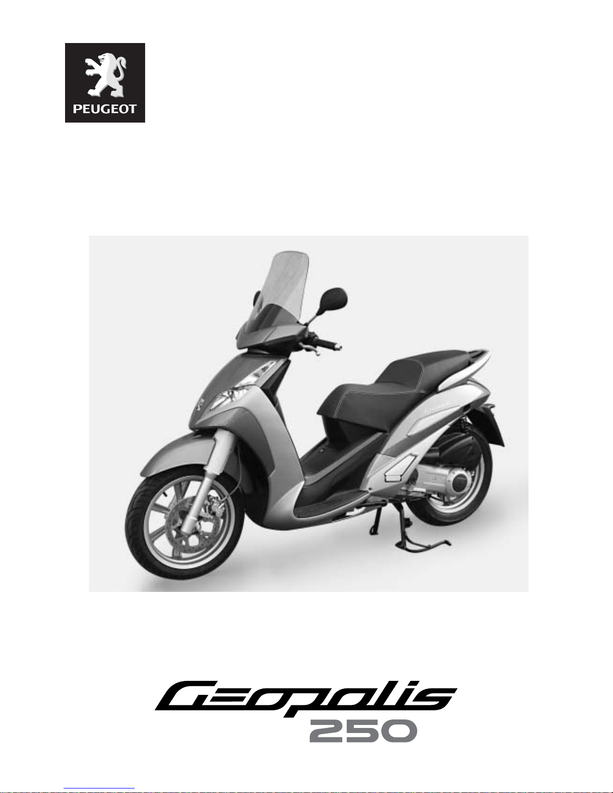
Direction commerciale
Animation technique réseau
WORKSHOP MANUAL
-
Page 2

Workshop manual
Technical network leadership
Reproduction or translat ion, even partial, is forbi dden without the written co nsent of Peugeot Motocyc les
Page 3
TABLE OF CONTENTS
1
Reproduction ou traduction, même partielle, interdite sans autorisation écrite de Peugeot Motocycles
TABLE OF CONTENTS
TABLE OF CONTENTS . ... ....................................... ... ... ... .... ... ....................................... ... ... ... ... ....................... 1
CHARACTERISTICS......................................................................................................................................... 4
Engine........................................................................................................................................................4
Capacities..................................................................................................................................................4
Chassis......................................................................................................................................................5
Dimensions and weight.................................................... ... ... .... ... ... ..........................................................5
Tyres ..........................................................................................................................................................5
SERVICE SCHEDULE AND COMMISSIONING............................................................................................... 6
Check.........................................................................................................................................................6
Change ......................................................................................................................................................6
Check and lubricate ...................................................................................................................................7
Reading the ECU fault codes.............................................. .......................................... .............................7
Test machine..............................................................................................................................................7
Battery preparation (Except battery without maintenance)* ......................................................................8
Checks before handing over to the customer.............................................................................................8
SPECIAL IMPORTANT POINTS....................................................................................................................... 9
Oil and fuel.................................................................................................................................................9
Starting up after overhauling the engine....................................................................................................9
Electricity....................................................................................................................................................9
Special features ........................... .... ...................................... .... ... ... ... .... ...................................................9
TIGHTENING TORQUES ................................. .... ... ... ... ... .......................................... .... ... .............................. 10
Engine part ..............................................................................................................................................10
Body panels .............................................................................................................................................11
Cycle part.................................................................................................................................................11
Standard ..................................................................................................................................................11
SPECIAL TOOLS ............................................................................................................................................ 12
ELECTRICITY..................................................................................................................................................13
4 stroke indirect injection system functional diagram...............................................................................13
Fuses and energy distribution..................................................................................................................14
LOCATION OF COMPONENTS...................................................................................................................... 15
Page 4
TABLE OF CONTENTS
2
Reproduction ou traduction, même partielle, interdite sans autorisation écrite de Peugeot Motocycles
BODY PANELS ............................................................................................................................................... 16
Location of body components..................................................................................................................16
Body component sequence of disassembly.............................................................................................17
Removal of the storage compartment......................................................................................................18
Removal of a RH or LH side cover...........................................................................................................18
Removal of the tank covers......................................................................................................................19
Removal of a RH or LH footboard............................................................................................................20
Removal of the front shield panel.............................................................................................................21
Removal of the rear shield panel .............................................................................................................22
Removal of the dirt shield ........................................................................................................................22
Removal of the instrument cluster ...........................................................................................................23
Removal of the battery holder..................................................................................................................23
SERVICE OPERATIONS................................................................................................................................. 24
Changing the engine oil and replacing the oil filter ....... ... ... ... .... ... ... .......................................... ..............24
Draining the relay box..............................................................................................................................25
Replacing the air filter ..............................................................................................................................26
Removal of the spark plug .......................................................................................................................27
Replacing the rollers and drive belt..........................................................................................................27
Draining the cooling circuit.......................................................................................................................28
Installing the valve clearance........................ ... ... .......................................... ... ... .... ... ..............................29
Replacing the brake pads ........................................................................................................................30
Front brake........................................................................................................................................................30
Rear brake............................................. ... .................................... ....................................................................30
SERVICING AN ABS/PBS SYSTEM .............................................................................................................. 31
Removal of the brake modulator..............................................................................................................31
Page 5
TABLE OF CONTENTS
3
Reproduction ou traduction, même partielle, interdite sans autorisation écrite de Peugeot Motocycles
MISCELLANEOUS OPERATIONS ................................................................................................................. 32
Procedure for reducing the fuel circuit pressure .............................................. ... .... ... ..............................32
Checking fuel pressure ............................................................................................................................33
Removal of the fuel pump........................................................................................................................34
Removal of the fuel gauge.......................................................................................................................34
Removal of the throttle box......................................................................................................................35
Removal of the lambda sensor ................................................................................................................35
Removal of the thermostat.......................................................................................................................37
Removal of the temperature sensor.........................................................................................................37
Removal of the regulator..........................................................................................................................37
Removal of the radiator............................................................................................................................38
Removal of the engine mounting assembly .............................................................................................38
Installing the engine mounting assembly...... ... ... ... ... .... ............................................. ... ... .... ... ... ... ...........39
Removal of the cylinder head...................................................................................................................40
Removal of the cylinder / piston...............................................................................................................40
Removal of the fork..................................................................................................................................41
Replacing the bearings of the steering system........................................................................................41
Steering system tightening method..........................................................................................................43
Removal of the suspension arm ..............................................................................................................44
Page 6
CHARACTERISTICS
4
Reproduction ou traduction, même partielle, interdite sans autorisation écrite de Peugeot Motocycles
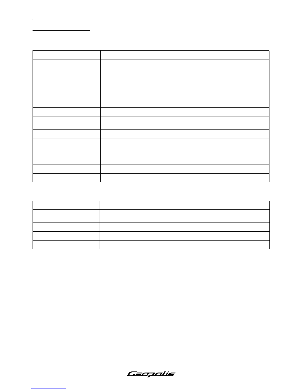
CHARACTERISTICS
Engine
Capacities
GEOPOLIS 250 cc.
Type.
4-stroke single-cylinder.
4 valves per cylinder with chain driven overhead camshaft
Cooling. Liquid.
Bore x stroke. 2 x 60 mm.
Cubic capacity. 244 cc.
Max. power output. 16.5 kW at 8000 rpm.
Max. torque rating. 6250 rpm.
Fuel supply.
Indirect electronic injection.
Magneti-Marelli
Lubrication. Trochoidal pump.
Transmission. By 2 variable pulleys and V-type belt.
Clutch. Centrifugal automatic.
Spark plug.
Champion RG 4 PHP
Exhaust. Catalytic.
Standards. Euro 3.
Fuel tank. 13.2 l 95 or 98 lead-free.
Engine oil.
1.3 L SAE 5W40.
Minimum grade: API SJ.
Relay box. 0.25 L SAE 75W85.
Coolant. 1.4 l. Peugeot coolant part number 754614
Fork. 212cc by tube Esso Univis 46 or Agip H Lift 46.
Page 7
CHARACTERISTICS
5
Reproduction ou traduction, même partielle, interdite sans autorisation écrite de Peugeot Motocycles
Chassis
Dimensions and weight
Tyres
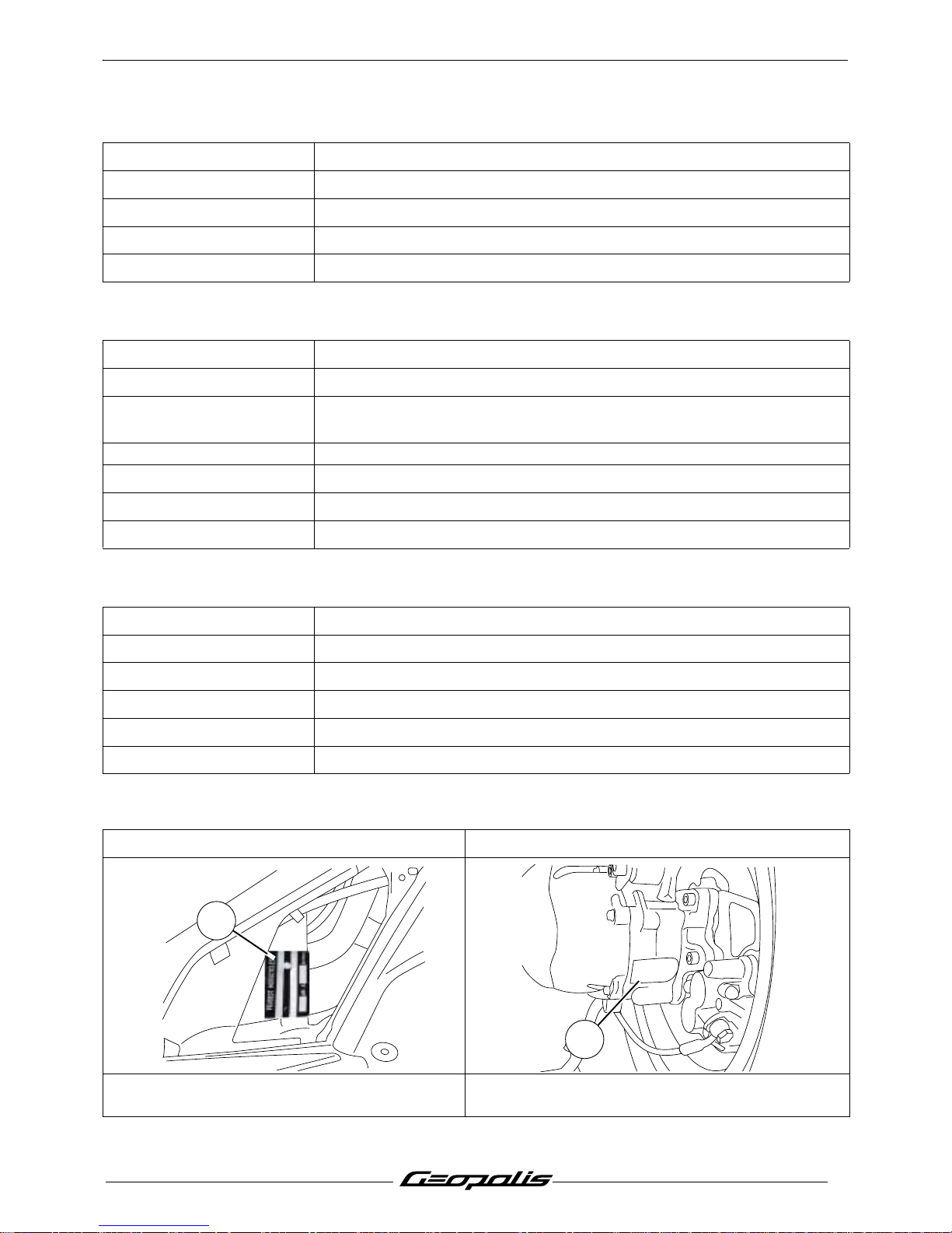
Chassis. Double cradle out of high-resistance steel tube.
Front suspension. Hydraulic telescopic fork. Ø37 mm.
Travel. 110 mm.
Rear suspension. 2 adjustable combined spring hydraulic shock absorbers.
Travel. 100 mm.
Overall length.
2170 mm.
Width at handlebar.
770 mm.
Height. (without rear-view
mirrors).
1425 mm.
Wheelbase. 1420 mm.
Ground clearance.
140 mm.
Saddle height.
784 mm.
Unladen weight.
159 kg.
Front wheel rim. 16 inch aluminium alloy.
Front tyre. .110/70 - 16.
Front tyre pressure. 2.1 bars.
Rear wheel rim. 16 inch aluminium alloy.
Rear tyre. .140/70 - 16.
Rear tyre pressure. 2.3 bars.
Chassis markings Engine marking
1. Manufacturer's plate. (Left side).
- VIN number of the RH side of the vehicle.
2. Engine number.
1
XXXXX
XXXXXXX
2
Page 8
SERVICE SCHEDULE AND COMMISSIONING
6
Reproduction ou traduction, même partielle, interdite sans autorisation écrite de Peugeot Motocycles
SERVICE SCHEDULE AND COMMISSIONING
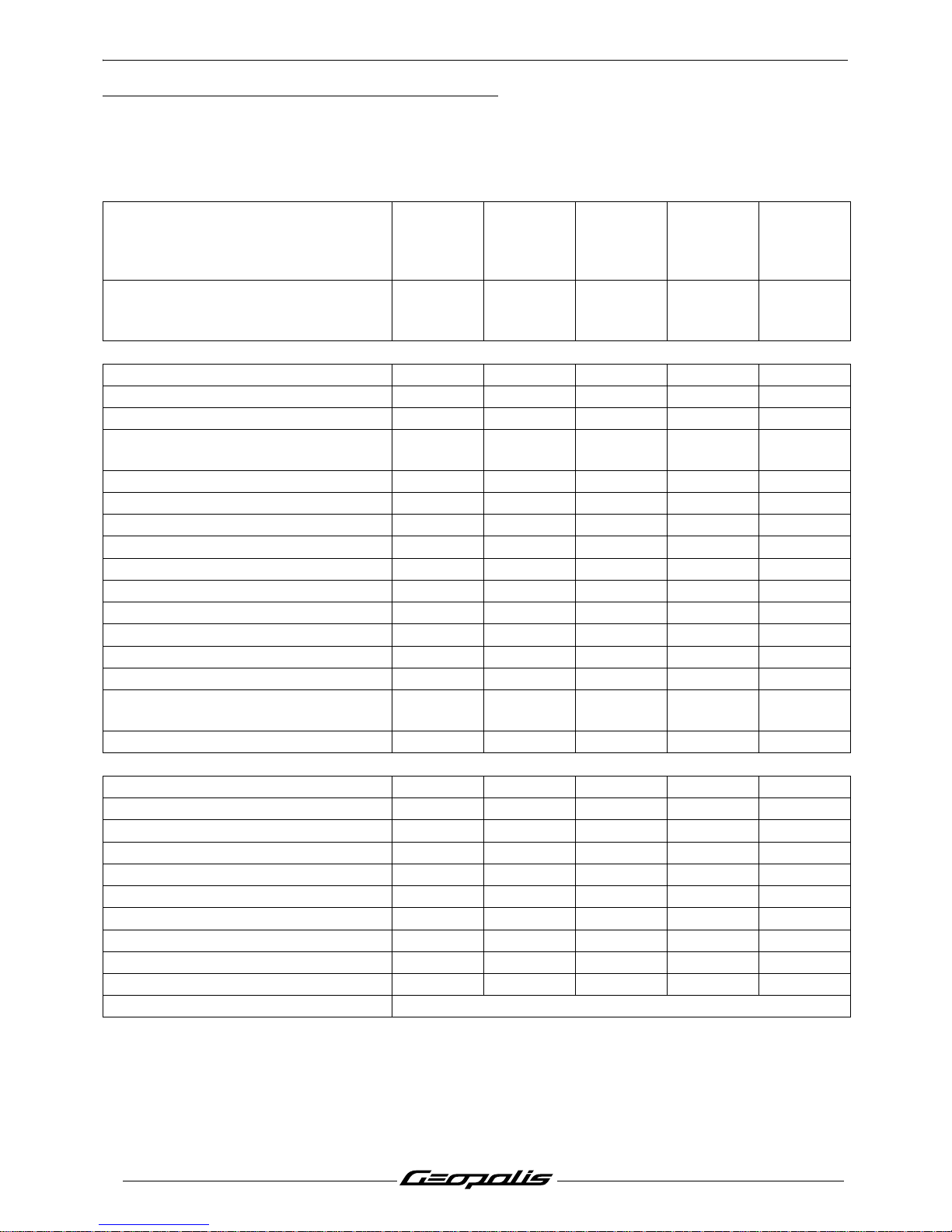
Heavy duty servicing is for vehicles used under "harsh" conditions: door-to-door deliveries, intensive
urban use (courier), short journeys with engine cold, dusty areas, ambient temperature over 30°C.
Service operations.
1000 kms
or
1 months
Every
5000 kms
or
12 months
Every
10000 kms
Every
15000 kms
Every
20000 kms
Heavy duty servicing. 500 kms
Every
2500 kms
Every
5000 kms
Every
7500 kms
Every
100000 k
ms
Check
Throttle cable play. C C C C
Steering column play. C C C C
Operation of electrical equipment. C C C C
Condition of front and rear brake
hydraulic controls.
CCC C
Condition of petrol pipes. C C C C
Condition of oil pipes. C C C C
Tyre pressures. C C C C
Tyre condition, pressure and wear. C C C C
Condition of the front suspension. C C C C
Condition of the rear suspension. C C C C
Brake fluid level. C C C C
Battery electrolyte level *. C C C C
Coolant level. CCCCC
Engine oil level. C
Tightening the engine mounting and
linkrod.
CCCC
Tightness of nuts and bolts. C C C C
Change
Spark plug. R
Inlet silencer/air filter. N N
Front brake pads #. C C C C
Rear brake pads #. C C C C
Drive pulley bearings and guides #. C C
Transmission belt. R
Belt anti-flapping roller #. C C
Engine oil (+ clean strainer). RCRCR
Engine oil filter. R R R
Relay box oil. R C R
Brake fluid and coolant. Once every 2 years
Page 9
SERVICE SCHEDULE AND COMMISSIONING
7
Reproduction ou traduction, même partielle, interdite sans autorisation écrite de Peugeot Motocycles
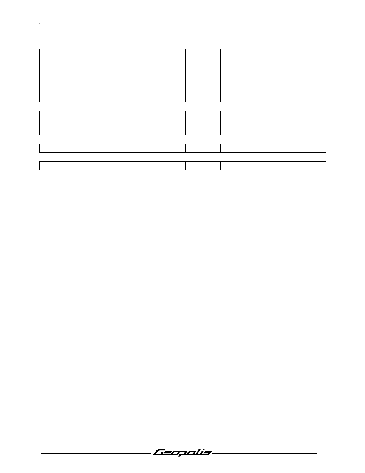
C: Check.
N: Clean.
R: Change.
G: Check and lubricate.
* Depending on equipment.
# Change if necessary.
Service operations.
1000 kms
or
1 months
Every
5000 kms
or
12 months
Every
10000 kms
Every
15000 kms
Every
20000 kms
Heavy duty servicing. 500 kms
Every
2500 kms
Every
5000 kms
Every
7500 kms
Every
100000 k
ms
Check and lubricate
Driven pulley: Moving flange and
needle bush.
GG
Drive pulley/Movable face. G G
Reading the ECU fault codes
Injection and ABS/PBS* system. CCCCC
Test machine
On road CCCCC
Page 10
SERVICE SCHEDULE AND COMMISSIONING
8
Reproduction ou traduction, même partielle, interdite sans autorisation écrite de Peugeot Motocycles
Battery preparation (Except battery without maintenance)*
Remove the battery.
Remove the 6 filler caps and the vent plug.
Fill with electrolyte to the level marked "UPPER LEVEL".
Electrolyte: (35% sulfuric acid = 1.28g/cm3).1 litre can P/N 752740; 5 litre can P/N 752741.
Leave the battery to stand for around half an hour.
Top up if necessary.
Charge the battery for at least 2 hours with a current of 0.4A.
Refit the battery and connect the vapour vent pipe.
Connect the red wire lug to the battery's + terminal, and the green wire lug to the battery's - terminal.
Then, the battery level should be topped up if necessary, after fully charging, using distilled water only.
Checks before handing over to the customer
Check the wheel nuts are tight.
Check nuts and bolts are tight.
Check brake adjustment and efficiency.
Check the tyre pressures cold.
Check operation of the lights, flashers, horn, and brake light.
Check the different warning lights work.
Carry out a road test.
* Depending on equipment.
Page 11
SPECIAL IMPORTANT POINTS
9
Reproduction ou traduction, même partielle, interdite sans autorisation écrite de Peugeot Motocycles
SPECIAL IMPORTANT POINTS
Oil and fuel
This engine is designed to run on 95 or 98 unleaded fuel only.
Fuel pipes must absolutely be changed if there are any signs of wear, cracks, etc.
The clips are specific, they must always be changed each time they are removed and replaced
with new genuine parts clips.
Petrol is highly inflammable, do not smoke in the working area and avoid pr oximity to flames or
sparks. Work in a clear and well-ventilated area.
Before carrying out any work, leave the engine to cool for at least 2 hours.
Starting up after overhauling the engine
When starting the engine hot or cold do not accelerate.
Check the coolant level in the header tank.
After road-testing the machine, check there are no fault codes left in the ECUs (using the diagnostic
tool).
Electricity
All components of the electrical system are powered with 12 volts DC.
The battery must not be disconnected while the engine is running and the voltage must be at least
7 volts for the ECU to function and enable engine starting.
Special features
An immobiliser built in the ECU provides the antitheft function by means of a transponder
The ECU features a diagnosis function which allows you to read memorized faults using th e diagnostic
tool.
Page 12
TIGHTENING TORQUES
10
Reproduction ou traduction, même partielle, interdite sans autorisation écrite de Peugeot Motocycles
TIGHTENING TORQUES
Engine part
Drive pulley 8 m.daN
Driven pulley 5.5 m.daN
Clutch plate and shoes 4.8 m.daN
Belt anti-flapping roller 1.5 m.daN
Transmission cover 1.2 m.daN
Relay box cover 2.5 m.daN
Filler cap. Relay box 1.5 m.daN
Flywheel magneto cover 1.2 m.daN
Stator 1m.daN
Engine speed sensor 0.5 m.daN
Rotor 9.5 m.daN
Freewheel 1.4 m.daN
Starter motor 1.2 m.daN
Automatic tensioner 1.2 m.daN
Automatic tensioner plug 0.5 m.daN
Spark plug 1.2 m.daN
Decompressor valve balance weight 0.8 m.daN
Decompressor valve housing 1.2 m.daN
Chain tensioner 1 m.daN
Camshaft stop plat 0.5 m.daN
Cylinder head bolt 1.2 m.daN
Cylinder head Procedure
Cylinder head cover 0.7 m.daN
Inlet manifold 1.2 m.daN
Injection rail 0.7 m.daN
Oil pressure switch 1.2 m.daN
Oil pump 0.6 m.daN
Oil pump pinion 1.2 m.daN
Oil pump cover 0.8 m.daN
Oil pan 1.2 m.daN
Crankcase 1.2 m.daN
Filler cap. Engine oil 2 .5 m.daN
Water pump cap 0.7 m.daN
Thermostatic valve cover 0.4 m.daN
Cooling system bleeder screw 0.3 m.daN
Page 13
TIGHTENING TORQUES
11
Reproduction ou traduction, même partielle, interdite sans autorisation écrite de Peugeot Motocycles
Body panels
Cycle part
Standard
Front mudguard. 0.8 to 1.2 m.daN
Handlebar cover. 0.2 to 0.4 m.daN
Front shield panels. 0.2 to 0.4 m.daN
Rear shield. 0.2 to 0.4 m.daN
Bottom panel. 0.2 to 0.4 m.daN
Floor panel. 0.4 to 0.6 m.daN
Saddle storage compartment. 0.8 to 1.2 m.daN
Rear panels. 0.2 to 0.4 m.daN
Grab handle. 2 to 2.5 m.daN
Rear mudguard. 0.4 to 0.6 m.daN
Front wheel spindle. 6.5 m.daN
Rear wheel bolt. 10 m.daN
Rear wheel spindle nut. 13.5 m.daN
Linkrod to engine pivot. 5.8 m.daN
Linkrod to frame pivot. 5.8 m.daN
Linkrod connecting pin 3.6 m.daN
Linkrod to frame adjustment locknut 10 m.daN
Linkrod to frame mounting bolt 6.8 m.daN
Shock absorber top mount. 4.5 m.daN
Shock absorber bottom mount. 4.5 m.daN
Exhaust to cylinder head mounting nut. 1.8 m.daN
Exhaust to casing mounting bolt. 2.5 m.daN
Exhaust clamp. 1.8 m.daN
Upper cone (in 2 operations). 4/2.2 m.daN
Upper cone locknut. Hand tightened
Steering locknut. 7.5 m.daN
Front brake caliper. 2.5 m.daN
Rear brake caliper. 2.5 m.daN
Front brake disc. 3 m.daN
Rear brake disc. 0.9 m.daN
Handle bar. 4 m.daN
Nut and bolt 5 mm diameter. 0.6 m.daN
Nut and bolt 6 mm diameter. 1 m.daN
Nut and bolt 8 mm diameter. 2.2 m.daN
Nut and bolt 10 mm diameter. 3.5 m.daN
Nut and bolt 12 mm diameter. 5.5 m.daN
Page 14
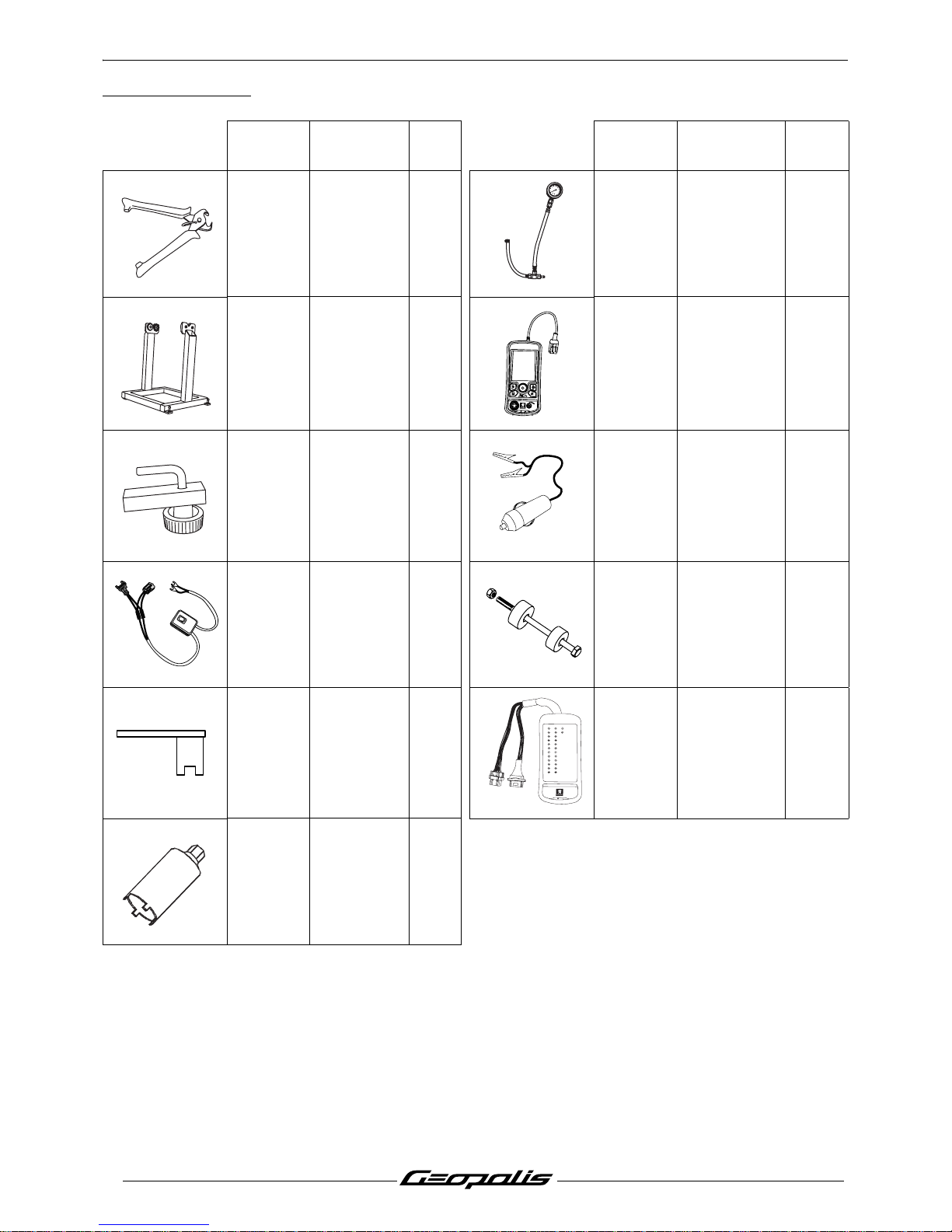
SPECIAL TOOLS
12
Reproduction ou traduction, même partielle, interdite sans autorisation écrite de Peugeot Motocycles
SPECIAL TOOLS
(*) New or modified tool.
Tool N° Designation
Used
with
Tool N° Designation
Used
with
750539
Tie-wrap
pliers
757877
Pressure
gauge
754278
Balance
support with
pins Ø15 and
Ø17 mm
758358 TEP 2005
755996 Hose clamp 758585
Power supply
cable tool
756017
Fuel injector
power supply
harness
758810
Steeing head
cup
installation
tool
756715
(*)
Tank gauge
spanner
758924
24 way
terminal block
(*)
757860 Steering tool
0
6
8
1
0
2
4
b
a
r
OK
TEP 2005
by
xxo
test
1
24
12
23
11
2210
21
9
20
8
197
186
175
16
15
141326
25
4
3
2
BM 426
b
y
xxo
t
e
s
t
Page 15
ELECTRICITY
13
Reproduction ou traduction, même partielle, interdite sans autorisation écrite de Peugeot Motocycles
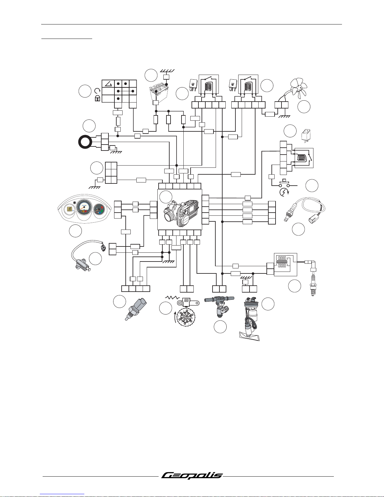
ELECTRICITY
4 stroke indirect injection system functional diagram
1. Injection ECU.
2. Engine speed and position sensor.
3. Petrol injector.
4. Petrol pump.
5. Ignition coil.
6. Lambda sensor.
7. Starter motor switch.
8. Starter motor relay.
9. Cooling fan.
10. Fan relay.
11. Injection relay.
12. Battery.
13. Ignition switch.
14. Transponder antenna.
15. Diagnostic plug.
16. Instrument panel.
17. Kickstand switch.
18. Engine temperature sensor.
1
2
V
-
2
5
A
21345
1
2
V
-
2
5
A
12345
2
1
3
4
5
1
2
6
3
OFF
ON
11
7
8
-
U
P
P
E
R
L
E
V
E
L
L
O
W
E
R
L
E
V
E
L
VE
B1A1
A3
VE
6
5
4
3
2
18
17
16
15
14
13
12
11
10
9
8
7
2
1
21
22
21
11
4
15 1413926 12
1
17
18
82420716 5 6
1
R
1
2
4
3
1
2
3
2
1
1
2
30A
F1
15A
F6
10A
F2
15A
F4
VE
VEVE
VE
JN
BCNR
NR
NR
RG
RG
VI
VE-NR
RG-BA
BA-BE
VE-NR
VE-NR
VE-JN
BE-NR
BA-VE
VI-BA
BE-NR
GR-RG
RG-NR
VI-NR
VE-NR
GR-RGMR-BA
BA-NR
12
+
BE
BA
VE
VE VE RG MR OR
VI
NR
Km
100
6
0
5
0
Km/h
40
30
20
10
70
8
0
9
0
1
0
0
120
140
160
80
60
40
80
40
120
20
0
M
Hrs
PEUGEOT
Page 16

ELECTRICITY
14
Reproduction ou traduction, même partielle, interdite sans autorisation écrite de Peugeot Motocycles
Fuses and energy distribution
Geopolis 250 cc
F1
Regulator.
Ignition switch.
F7.
F2
Injection ECU.
Injection relay:
HT coil.
Petrol injector.
Petrol pump.
Lambda sensor.
Fan relay.
F4
Instrument panel.
Lighting relay.
Fan relay.
F5
Instrument panel.
Dip switch (main/low headlight).
Horn.
Number plate light.
Sidelight.
Stop light contact.
F6
Injection ECU.
Transponder antenna.
Diagnostic plug.
Injection relay.
Lighting relay.
F7 Accessory socket.
RG
GR-BE
GR-RG
GR-RG
+B
-
UPPER LE
VEL
LOW
ER LE
VEL
RG
RG-NR
GR-NR
NR
6
5
1
2
4
7
F1-30A
F6-7,5A
F5-15A
F2-10A
F4-15A
F7-10A
X
X
X
X
X
X
X
X
X
X
X
X
X
X
Page 17
LOCATION OF COMPONENTS
15
Reproduction ou traduction, même partielle, interdite sans autorisation écrite de Peugeot Motocycles
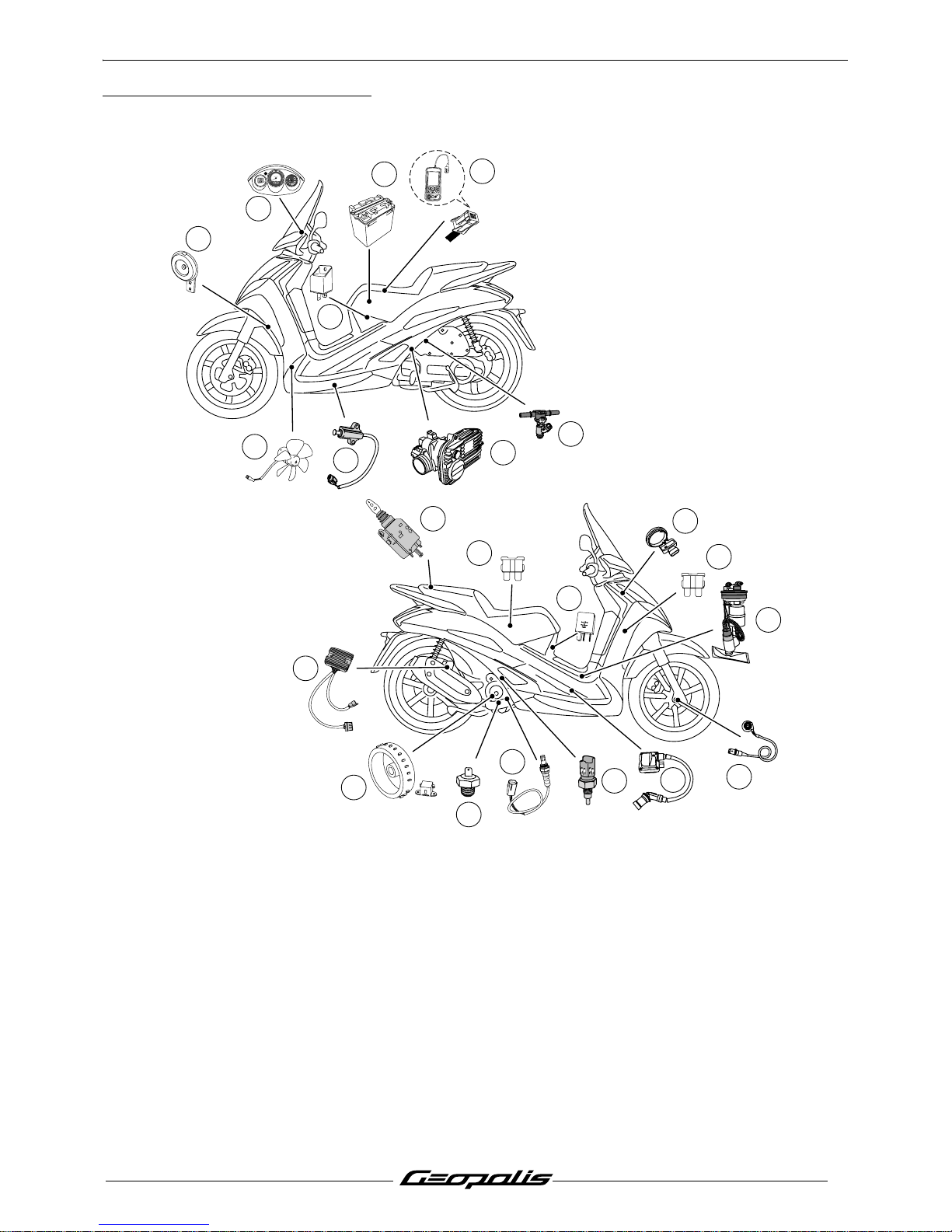
LOCATION OF COMPONENTS
1. Injection ECU.
2. Engine speed and position sensor.
3. Engine temperature sensor.
4. Battery.
5. Lambda sensor.
6. Petrol injector.
7. Ignition coil.
8. Transponder antenna
9. Petrol pump.
10.Diagnostic light.
11.Diagnostic plug.
12.Starter motor relay
13.Fuses
14.10 A fuse. (Accessory socket. 12V).
15.Oil pressure switch
16.Motor-driven fan.
17.Lighting relay/Fan relay/Power supply
relay.
18.Voltage regulator.
19.Horn.
20.Saddle lock.
21.Machine speed sensor.
22.Kickstand switch.
-
UPPER LE
VEL
L
OW
ER LE
VEL
12V - 25A
11
8
9
14
21
3
5
15
2
7
1
6
4
12
10
19
22
20
17
13
16
OK
TEP 2005
by
xxo
test
E638534
503950140101
22/02/06 9 :
39 :
07
0064
CE 0051
e24
18
K
m
1
0
0
6
0
5
0
K
m
/
h
4
0
30
2
0
10
7
0
8
0
9
0
1
0
0
1
2
0
140
160
8
0
6
0
40
80
4
0
1
2
0
2
0
0
M
H
r
s
PEUGEOT
Page 18
BODY PANELS
16
Reproduction ou traduction, même partielle, interdite sans autorisation écrite de Peugeot Motocycles
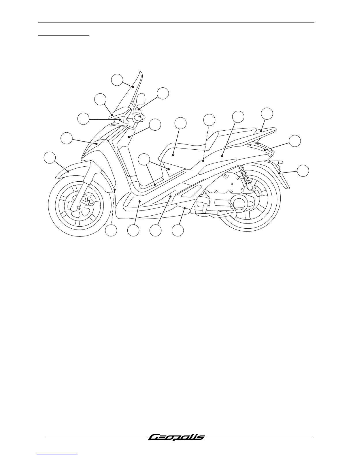
BODY PANELS
Location of body components
1. Handlebar front fairing.
2. Wind protector.
3. Counter panel.
4. Lower handlebar cover.
5. Front top cover panel.
6. Front shield panels.
7. Mudguard.
8. Bottom panel.
9. Saddle.
10.Tank streamlining.
11.Rear shield.
12.Footboard.
13.Access door.
14.Luggage carrier.
15.Helmet compartment.
16.Mudflap.
17.Rear cover.
18.Side panels.
19.Front mudguard.
13 8127
1
2
6
9
10
19
3
11
18
15
14
17
16
4
Page 19
BODY PANELS
17
Reproduction ou traduction, même partielle, interdite sans autorisation écrite de Peugeot Motocycles
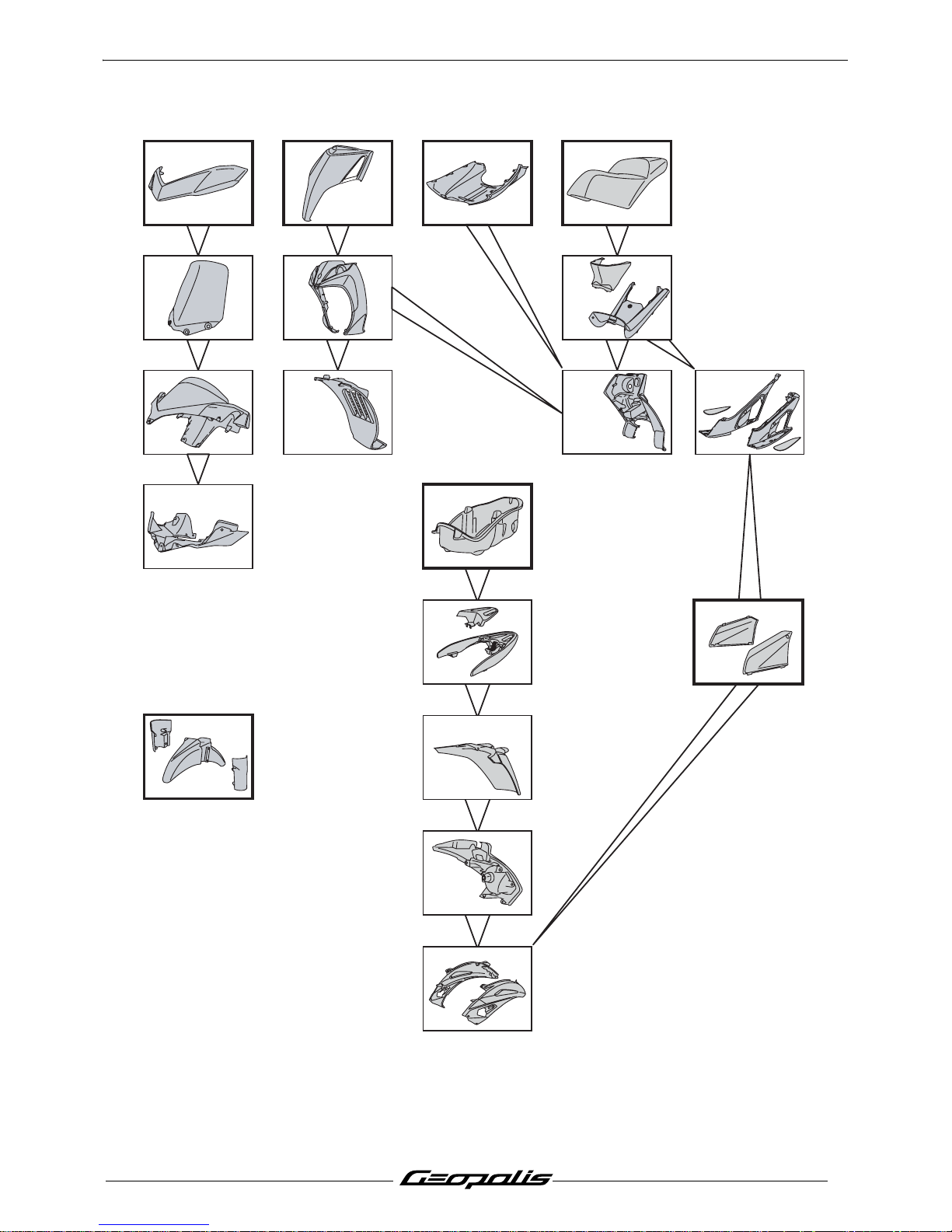
Body component sequence of disassembly
* This item may be removed on its own.
1* 5* 8* 9*
26 10
37 1112
4
13*
18
19*
17
16*
15*
14
Page 20
BODY PANELS
18
Reproduction ou traduction, même partielle, interdite sans autorisation écrite de Peugeot Motocycles
Removal of the storage compartment
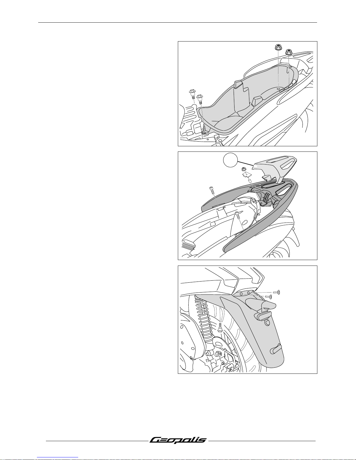
Procedure 1.
- Remove the storage compartment.
(2 screws and 2 nuts).
Removal of a RH or LH side cover
Procedure 2.
- Remove the storage compartment. See:
Procedure 1. page 18.
- Remove the luggage carrier trim. (1)
- Remove the luggage carrier. (2 screws and
1 nut).
- Remove the splash guard. (4 screw).
- Disconnect the license plate light.
1
Page 21
BODY PANELS
19
Reproduction ou traduction, même partielle, interdite sans autorisation écrite de Peugeot Motocycles
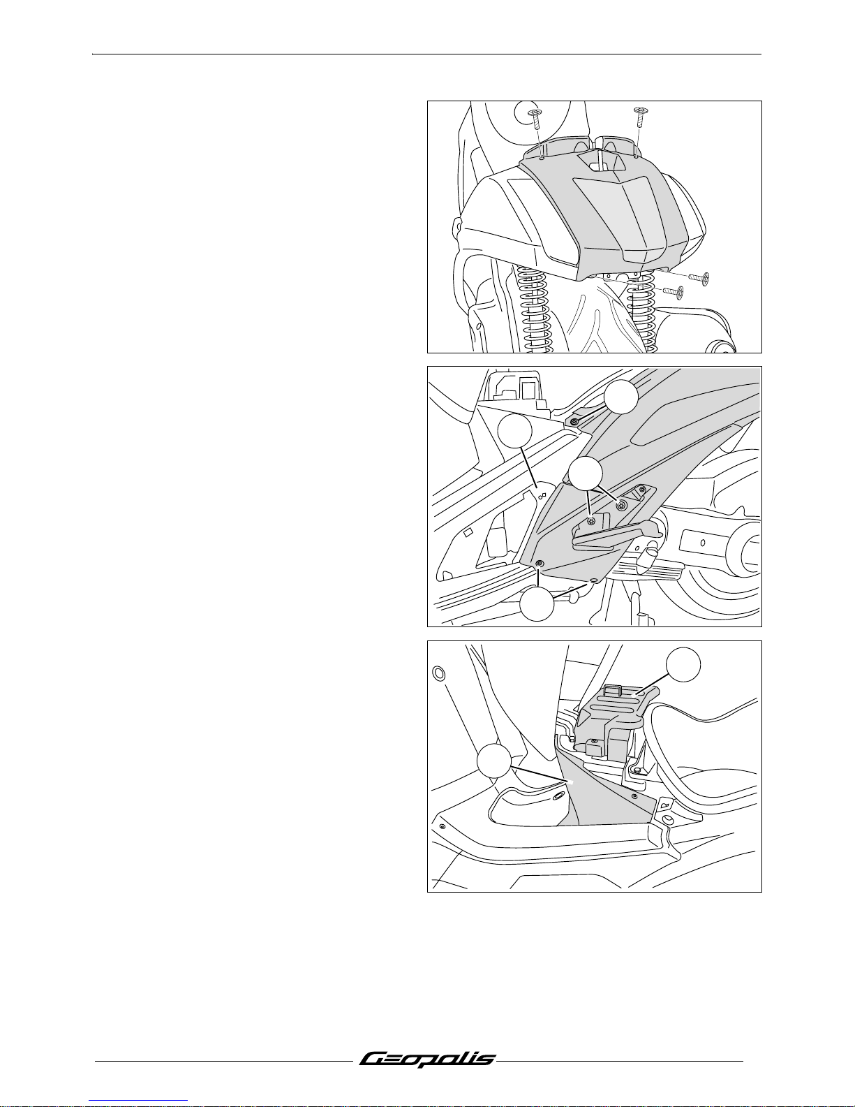
- Remove the rear body cover. (4 screw).
- Remove the access door. (1 screw).
- Remove the 2 screws that secure the
footrest. (2)
- Remove the rear cover 3 fixing screws. (3)
- Unclip the support (A) and remove the side
panel together with the footrest.
Removal of the tank covers
Procedure 3.
- Remove the saddle. (2 screw).
- Remove the battery cover. (1)
- Open the tank filler cap door.
- Remove the upper fairing. (2)
A
2
3
3
1
2
Page 22
BODY PANELS
20
Reproduction ou traduction, même partielle, interdite sans autorisation écrite de Peugeot Motocycles
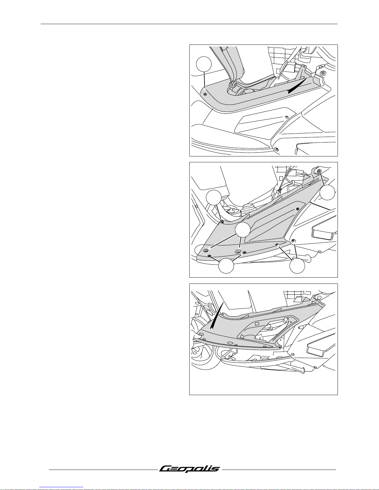
- Remove the 2 fixing bolts. (3)
- Remove the fuel tank cover panel by sliding
it rearwards.
Removal of a RH or LH footboard
Procedure 4.
- Remove the tank cover panel. See:
Procedure 3. page 19.
- On each side remove:
• 2 washer head screws.Ø6 mm. (1)
• 1 washer head screw.Ø5 mm. (2)
• 5 plastic screws.(3)
- Remove the access door.
- Separate the front of the footboard which is
linked to the rear part of the leg shield panel.
- Remove the footboard.
3
3
1
2
3
3
Page 23
BODY PANELS
21
Reproduction ou traduction, même partielle, interdite sans autorisation écrite de Peugeot Motocycles
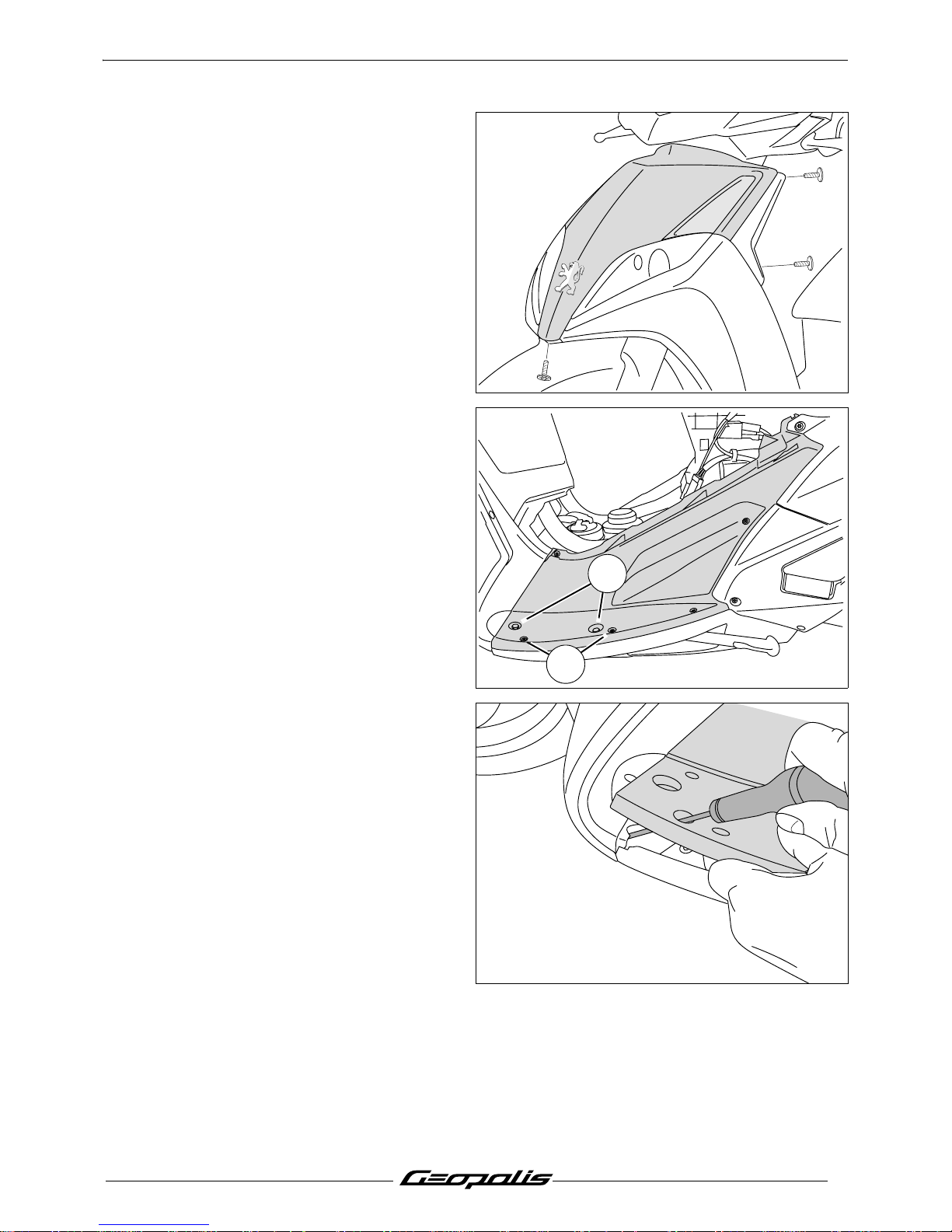
Removal of the front shield panel
Procedure 5.
- Remove the front top cover panel. (5 screw).
- Remove the footboard mat.
- On each side remove:
• 2 washer head screws. Ø6 mm. (1)
• 2 plastic screws. (2)
- Lift the footboard in order to reach the screw
that secures the shield panel.
2
1
Page 24
BODY PANELS
22
Reproduction ou traduction, même partielle, interdite sans autorisation écrite de Peugeot Motocycles
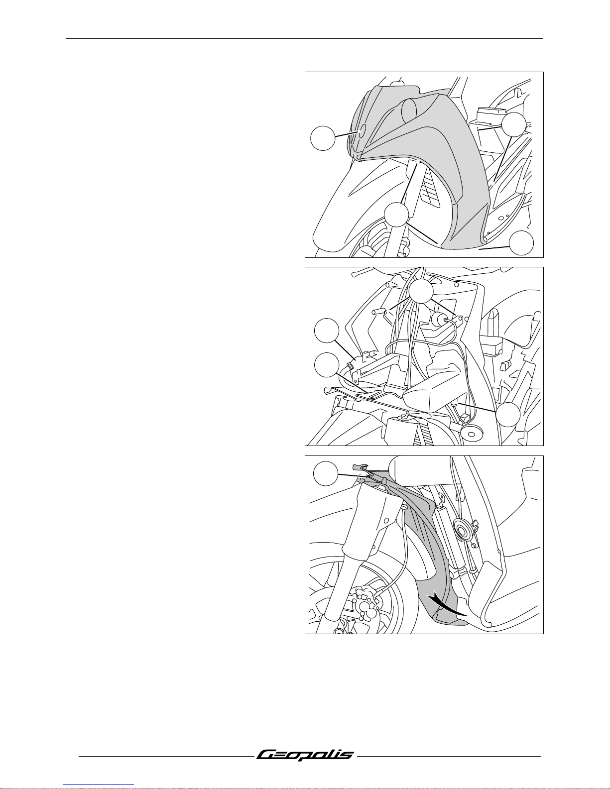
- On each side remove:
• 5 plastic screws. (3)
- Remove the centre screw. (4)
- Remove the front legshield assembly.
- Disconnect the lighting and direction
indicator connections.
Removal of the rear shield panel
- Remove the footboards. See: Procedure 4.
page 20.
- Remove the front legshield assembly. See:
Procedure 5. page 21.
- Remove the header tank. (Right side) (1)
- Remove the fuse holder. (Right side) (2)
- Disconnect the accessory plug. (Left
side) (3)
- Remove the 2 fixing bolts. (4)
- Remove the rear shield panel.
Removal of the dirt shield
- Remove the front legshield assembly. See:
Procedure 5. page 21.
- Remove the dirt shield (1) by unclipping it
from the upper bracket and by swivelling it to
the right or to the left
4
3
3
3
1
2
4
3
1
Page 25
BODY PANELS
23
Reproduction ou traduction, même partielle, interdite sans autorisation écrite de Peugeot Motocycles
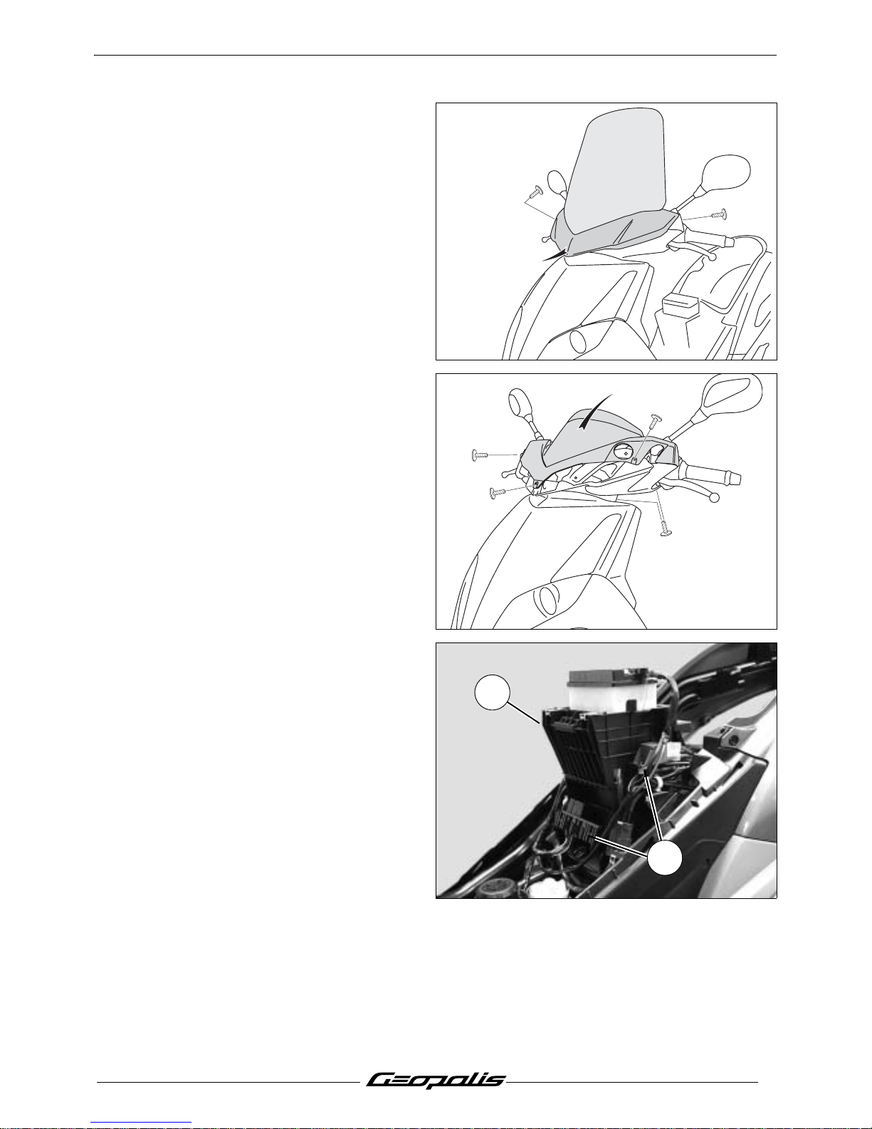
Removal of the instrument cluster
- Remove the handlebar front cover.
(2 screw).
- Remove the screen. (4 screw).
- Remove the handlebar rear cover and
instrument cluster assembly. (7 screw).
- Disconnect the instrument cluster.
Removal of the battery holder
Procedure 6.
- Remove the tank cover panel. See:
Procedure 3. page 19.
- Remove the storage compartment. See:
Procedure 1. page 18
- Disconnect and remove the battery.
- Unclip from the battery holder:
• The fuses. (1)
• The relays. (2)
- Remove the battery bracket. (3 screw).
2
1
Page 26
SERVICE OPERATIONS
24
Reproduction ou traduction, même partielle, interdite sans autorisation écrite de Peugeot Motocycles
SERVICE OPERATIONS
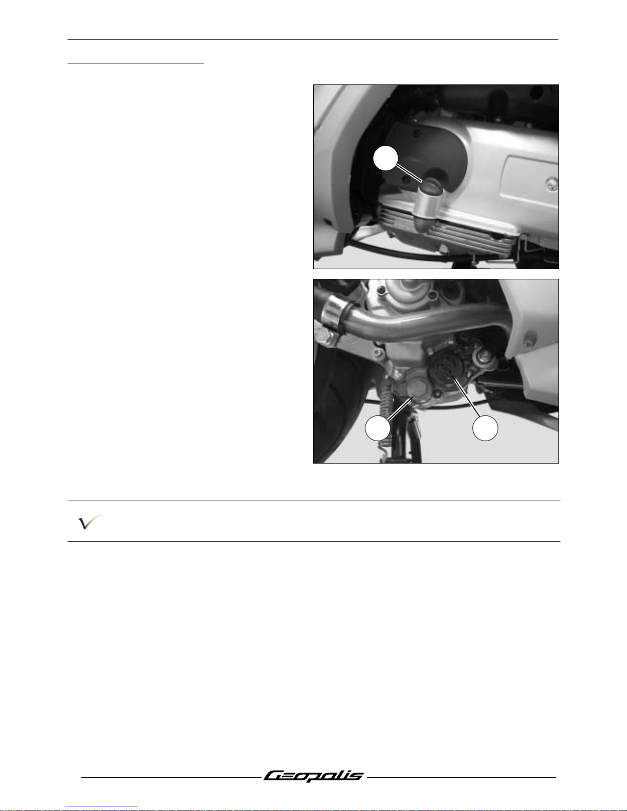
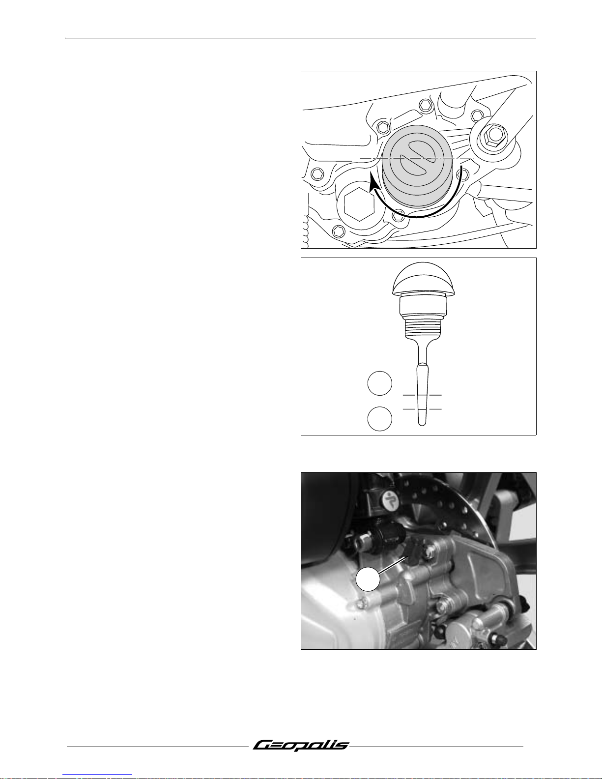
Changing the engine oil and replacing
the oil filter
- Remove the engine's oil filler cap. (1)
- Remove the cap and the filter to drain oil
from the engine. (2)
- Remove the oil filter by unscrewing it. (3)
Drain the engine when it is warm.
Wear gloves in order not to get burnt.
1
32
Page 27
SERVICE OPERATIONS
25
Reproduction ou traduction, même partielle, interdite sans autorisation écrite de Peugeot Motocycles
- Lubricate the rubber seal of a new oil filter.
- Screw the filter until it is in contact with the
engine casing and then screw the filter a half
turn by hand.
- Fit the oil strainer and the drain plug.
Tightening torque: 2.5 m.daN.
- Fill the engine with 1.3 L motor oil through
the filler hole.
- Fit the filler cap.
- Start the engine, let it run for a few minutes
and then stop it.
- Check the oil level by using the marks on the
filler cap.
A. Oil level high.
B. Oil level low.
- Add oil if necessaire.
Note: Check the level with the machine par-
ked on its centre stand, on level
ground.
Draining the relay box
- Remove the relay box filler cap. (1)
1
A
B
1
Page 28
SERVICE OPERATIONS
26
Reproduction ou traduction, même partielle, interdite sans autorisation écrite de Peugeot Motocycles
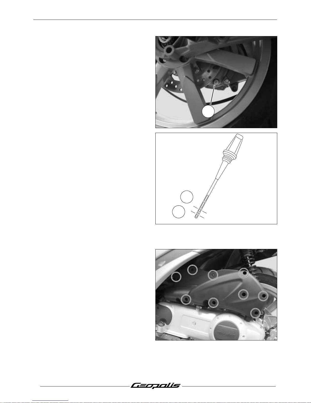
- To drain the engine remove the cap and let
the oil drip. (2)
- Fit the drain plug.
Tightening torque: 1.5 m.daN.
- Fill the relay box with 0.25 L oil through the
filler hole.
- Check the oil level by using the marks on the
filler cap.
A. Oil level high.
B. Oil level low.
- Add oil if necessary.
Note: Check the level with the machine par-
ked on its centre stand, on level
ground.
Replacing the air filter
- Remove the air filter cover (9 bolts) and its
seal.
2
A
B
Page 29
SERVICE OPERATIONS
27
Reproduction ou traduction, même partielle, interdite sans autorisation écrite de Peugeot Motocycles
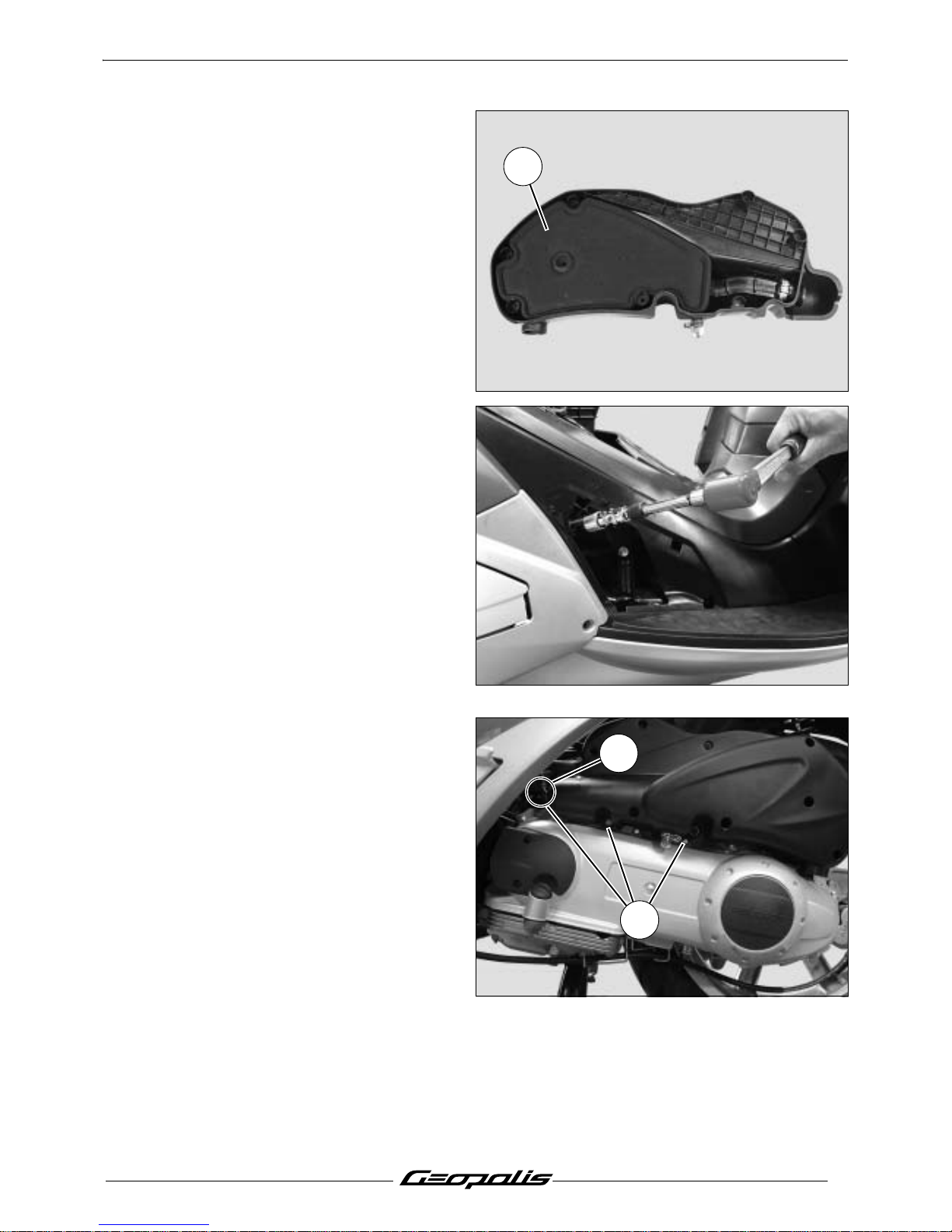
- Remove the air filter. (1)
Removal of the spark plug
- Remove the storage compartment. See:
Procedure 1. page 18.
- Remove the access door.
- Disconnect the suppressor.
- Remove the spark plug.
Essential precautions: When re-installing,
srew in the spark plug (a few turns)
by hand. For torquing, use a spark
plug wrench equipped with a dial.
- Tighten the spark plug.
Tightening torque: 1.2 m.daN.
Replacing the rollers and drive belt
- Remove the storage compartment. See:
Procedure 1. page 18.
Remove the 3 air filter box fixing bolts (1).
(including 1 screw, 1 nut and 1 pin in (A).
- Remove the transmission cover. (Refer to
the 250cc Engine workshop manual.
4 valves. Reference 758850.
1
A
1
Page 30
SERVICE OPERATIONS
28
Reproduction ou traduction, même partielle, interdite sans autorisation écrite de Peugeot Motocycles
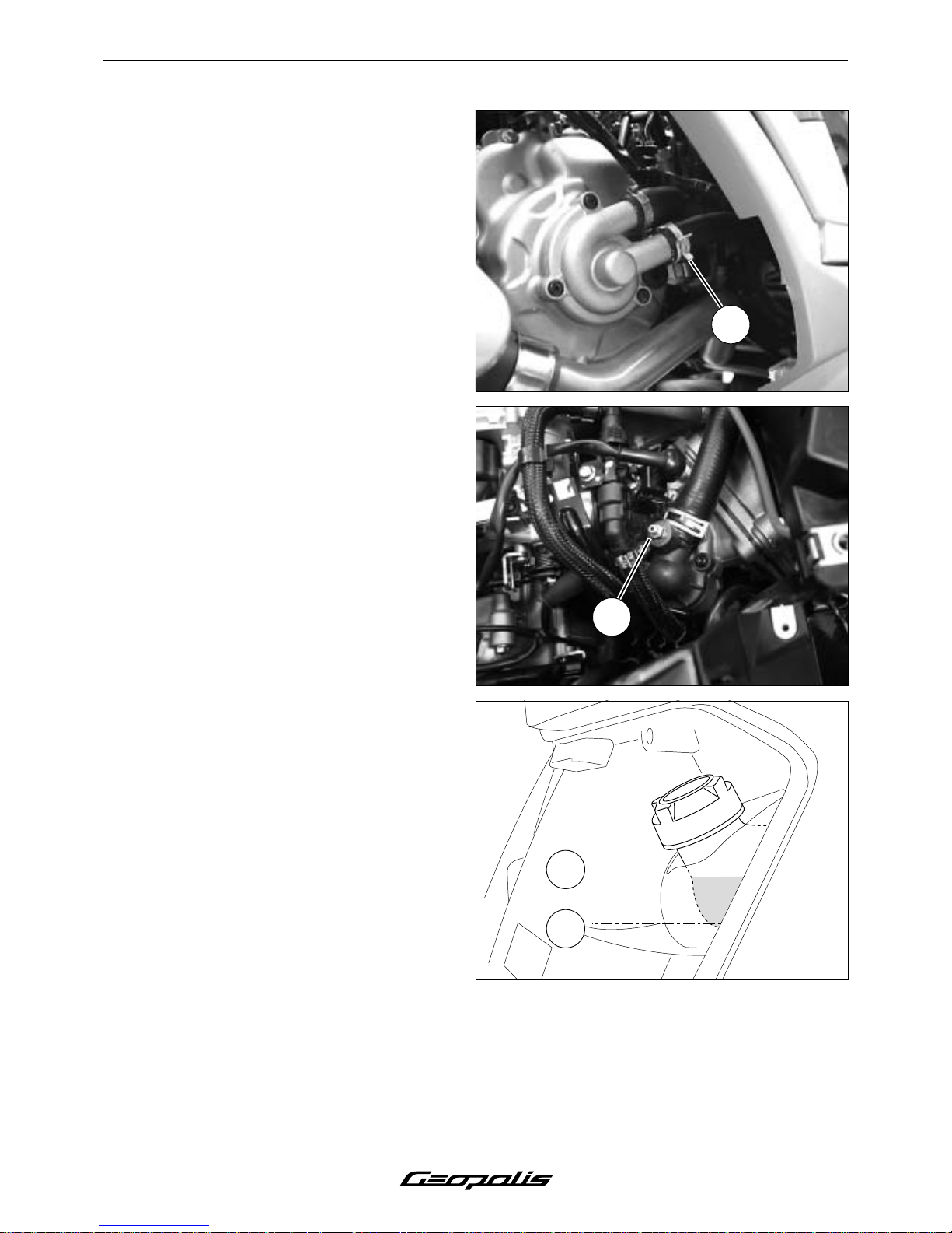
Draining the cooling circuit
- Remove the storage compartment. See:
Procedure 1. page 18.
- Remove the header tank cap.
- Disconnect the lower pump from the coolant
pump to drain the cooling system. (1)
Note: The cooling system is drained when
the engine is cold.
- Connect the lower hose to the water pump
- Fill the circuit with 1.3 L of coolant.
- Loosen the bleeder screw (2) to remove air
contained in the engine.
- Close the bleeder screw.
Tightening torque: 0.3 m.daN.
- Start the engine and accelerate in order to
warm it up.
- Stop the engine once it reaches its operating
temperature. (Approximately 90°C).
- Check the coolant level in the header tank.
- If necessary add coolant in the header tank.
A. Maximum level.
B. Minimum level.
Note: Check the level with the machine par-
ked on its centre stand, on level
ground.
1
2
B
A
Page 31
SERVICE OPERATIONS
29
Reproduction ou traduction, même partielle, interdite sans autorisation écrite de Peugeot Motocycles
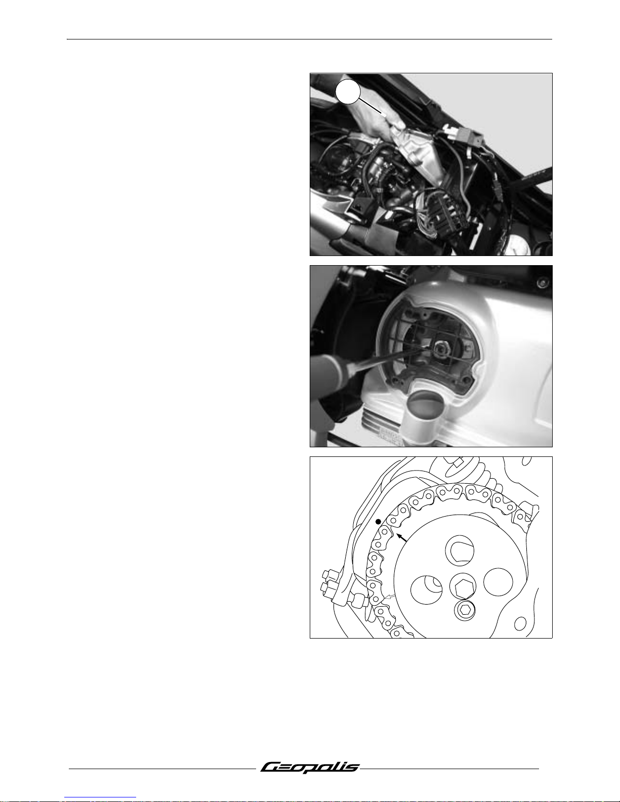
Installing the valve clearance
- Remove the storage compartment. See:
Procedure 1. page 18
- Remove the oil vapour suction box.
(4 screw).
- Remove the rocker cover. (5 screw).
Tightening torque: 0,7 m.daN.
- Remove the transmission air filter cover.
(2 screw)
- Using a screwdriver, turn the crankshaft so
as to align the camshaft gear mark (4V)
with the cylinder head mark.
1
4V
2V
Page 32
SERVICE OPERATIONS
30
Reproduction ou traduction, même partielle, interdite sans autorisation écrite de Peugeot Motocycles
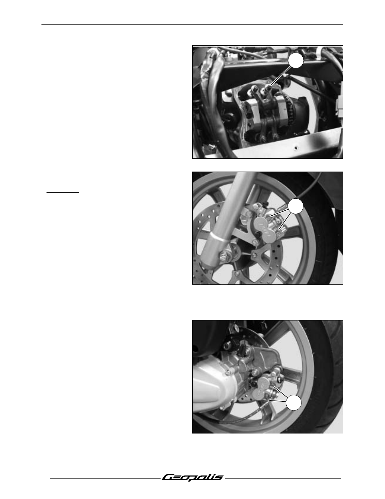
- Loosen the lock nut of the rocker
adjustment screw. (1)
- By means of feeler gauges, adjust the
clearance of every valve by acting on the
rocker set screw.
Clearances:
• 10/100 at the intake.
• 15/100 at the exhaust.
- Immobilize the rocker set screw.
- Tighten the locknut without altering the
adjustment.
- Check the adjustment.
Replacing the brake pads
Front brake
- Remove the 2 spindles (1). (or 1 spindle and
1 pin in the ABS/PBS version).
- Remove the calliper. (2 screw).
- Remove the brake pads.
Mini. thickness: 1.5 mm.
- When refitting the brake pads, push the
pistons all the way into their housing.
Note: After refitting, actuate the brake
levers several times to bring the
brake pads against the brake disc.
Rear brake
- Remove the 2 spindles (2). (or 2 spindles in
the ABS/PBS version.
- Remove the calliper. (2 screw).
- Remove the brake pads.
Mini. thickness: 1.5 mm.
- When refitting the brake pads, push the
pistons all the way into their housing.
Note: After refitting, actuate the brake
levers several times to bring the
brake pads against the brake disc.
1
1
2
Page 33
SERVICING AN ABS/PBS SYSTEM
31
Reproduction ou traduction, même partielle, interdite sans autorisation écrite de Peugeot Motocycles
SERVICING AN ABS/PBS SYSTEM
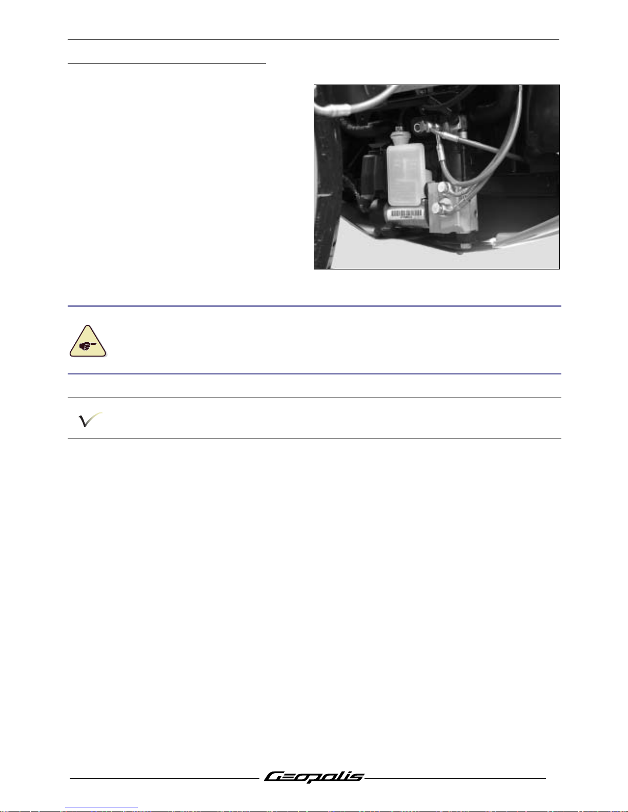
Removal of the brake modulator
- Remove the front shield panel. See:
Procedure 5. page 21.
- Remove the mudguard.
- Disconnect the modulator.
- Pinch the supply hose of the tank using the
hose clamp P/N 755996
- Disconnect the supply hose.
- Disconnect the hydraulic controls.
- Remove the brake modulator.
Hold the brake levers at 20 mm from the rest position using plastic straps. This operation allows
you to close the circuits and to avoid emptying the hydraulic controls when disconnecting the
modulator.
Place a pan under the modulator so that the brake fluid will drip into it.
Do not remove the master cylinder covers.
Drain the braking circuit (Refer to the workshop manual (See manual and method N° 32))
Page 34
MISCELLANEOUS OPERATIONS
32
Reproduction ou traduction, même partielle, interdite sans autorisation écrite de Peugeot Motocycles
MISCELLANEOUS OPERATIONS
Procedure for reducing the fuel circuit
pressure
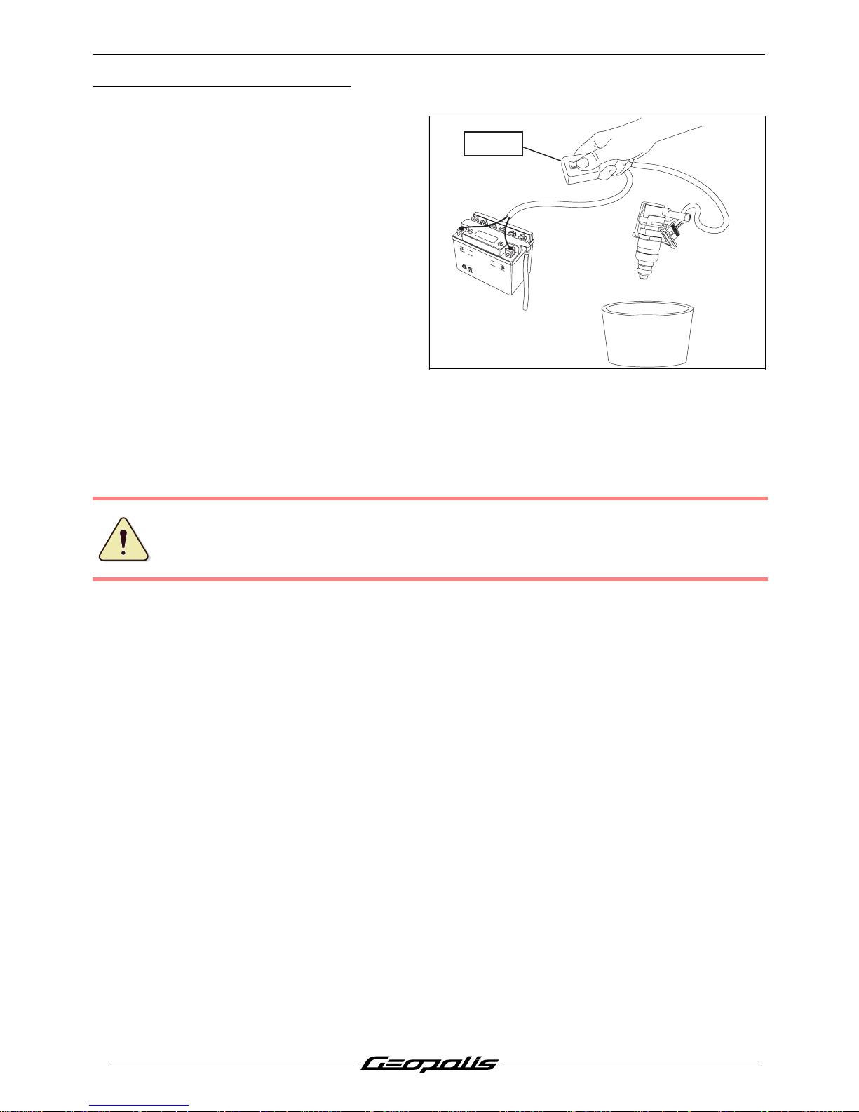
Procedure 7.
- Remove the storage compartment. See:
Procedure 1. page 18.
- Disconnect the fuel injector.
- Remove the fuel injector.
- Remove the fuel injector without
disconnecting the supply hose.
- Connect the fuel injector power supply
harness tool P/N 756017 to the fuel injector
and the battery.
- Place the injector above a pan.
- Actuate the contact switch of the tool 2 times
for 5 seconds while respecting a released
time of 5 seconds between each action, in
order to drop the pressure inside the supply
hose of the fuel manifold.
The pressurised jet of fuel may be dangerous for the skin, do not expose the hands to the jet of
fuel when opening the injector.
UPPER LEVEL
LOWER LEVEL
756017
Page 35
MISCELLANEOUS OPERATIONS
33
Reproduction ou traduction, même partielle, interdite sans autorisation écrite de Peugeot Motocycles
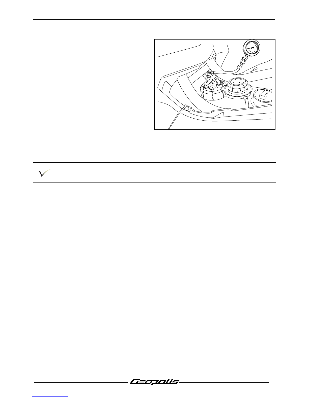
Checking fuel pressure
- Remove the tank cover panel. See:
Procedure 3. page 19.
- Carry out the procedure for lowering the
pressure in the fuel system. See:
Procedure 7. page 33.
- Disconnect the fuel supply hose.
- Insert the pressure gauge P/N 757877
between the gauge well and the supply
hose.
- Always use hose clamps that are in good
condition.
- Turn the ignition on 3 times to bleed the fuel
system.
- With the engine stopped, check the fuel
pressure which must be 2.5 bars when
switching on the fuel pump.
Before disconnecting the pressure gauges, lower the fuel pressure in the fuel system.
Always reinstall the hoses with new hose clamps.
0
6
8
10
2
4
bar
Page 36
MISCELLANEOUS OPERATIONS
34
Reproduction ou traduction, même partielle, interdite sans autorisation écrite de Peugeot Motocycles
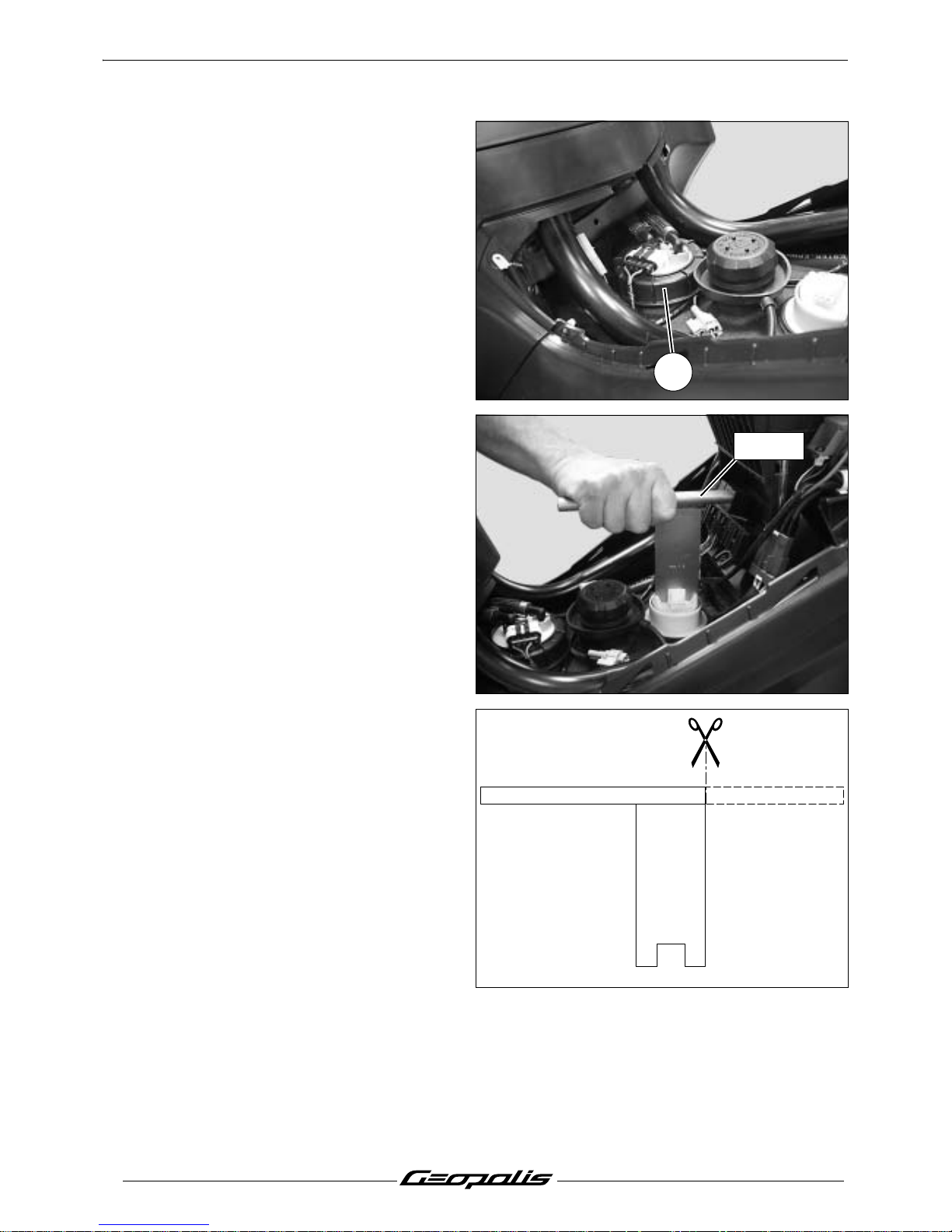
Removal of the fuel pump
- Remove the tank cover panel. See:
Procedure 3. page 19.
- Carry out the procedure for lowering the
pressure in the fuel system. See:
Procedure 7. page 33.
- Disconnect the fuel pump.
- Disconnect the 2 fuel pipes.
- Loosen by hand the pump locking ring. (1)
- Remove the fuel pump.
Removal of the fuel gauge
- Remove the tank cover panel. See:
Procedure 3. page 19.
- Disconnect the fuel gauge.
- Using tool P/N 756715, remove the fuel
gauge
Note: Modify the tool P/N 756715 as shown
in the sketch in order to use it with
the Geopolis.
1
756715
Page 37
MISCELLANEOUS OPERATIONS
35
Reproduction ou traduction, même partielle, interdite sans autorisation écrite de Peugeot Motocycles
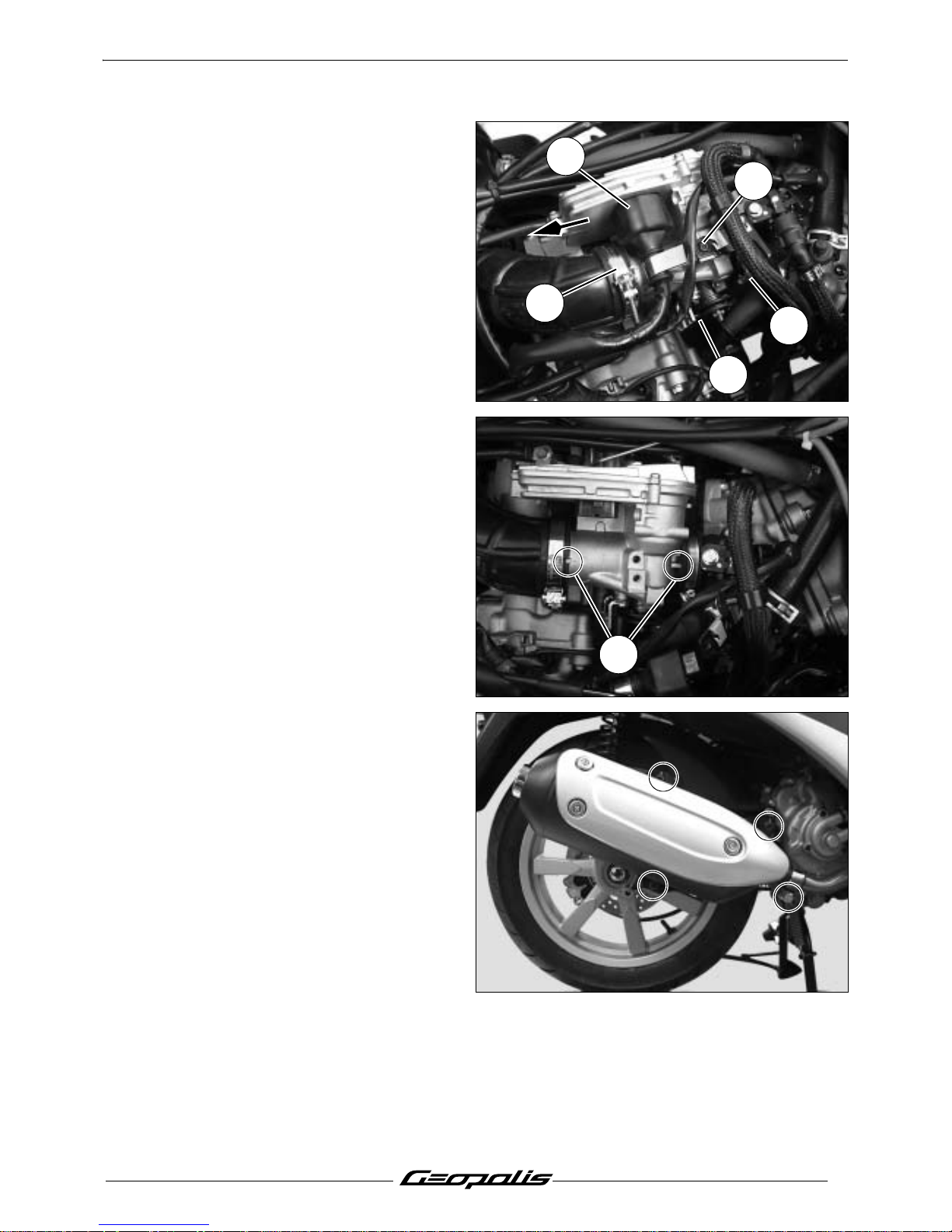
Removal of the throttle box
- Remove the storage compartment. See:
Procedure 1. page 18.
- Disconnect the battery.
- Remove the screw (1) that secures the
wiring harness clamp and the fuel hose
anchor bracket.
- Disconnect the throttle unit. (2)
- Disconnect the throttle cable (3) from the
throttle unit.
- Loosen the collars. (4)
- Remove the throttle box by first pulling it off
the intake coupling.
Reassembly: Make sure the throttle box is
properly positioned in the flexible
couplings and that the centring pins
are locked in. (A)
Check: Using the diagnostic tool, ch ec k for
fault codes, clear them if necessary.
Removal of the lambda sensor
- Remove the bottom panel.
- Remove the exhaust. (1 collar and
3screws).
- Remove the header pipe.
1
3
2
4
4
A
Page 38
MISCELLANEOUS OPERATIONS
36
Reproduction ou traduction, même partielle, interdite sans autorisation écrite de Peugeot Motocycles
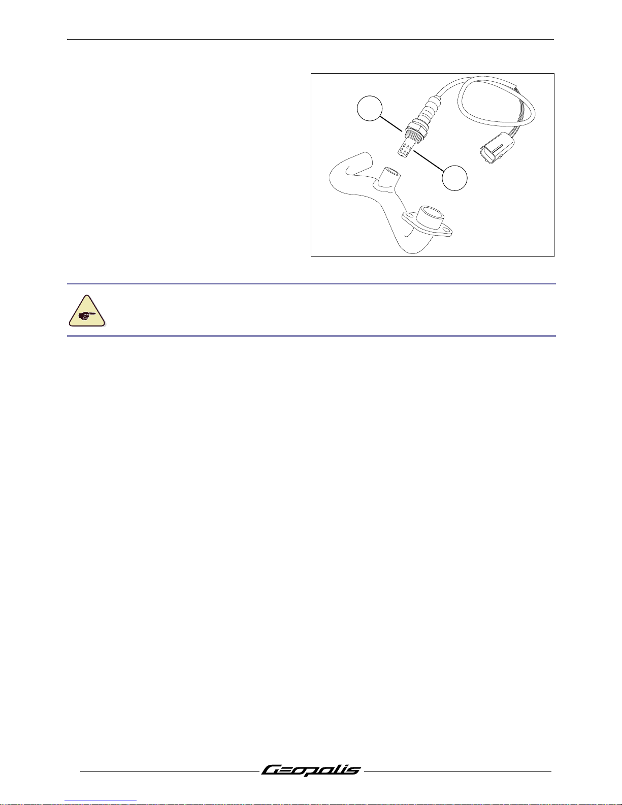
- Disconnect and remove the Lambda sensor.
Note: When reinstalling, lubricate the
threads (A) of the sensor with graphite grease.
In order not to damage the Lambda sensor, never lubricate or clean the end piece (B) which is
exposed to the exhaust gas.
A
B
Page 39
MISCELLANEOUS OPERATIONS
37
Reproduction ou traduction, même partielle, interdite sans autorisation écrite de Peugeot Motocycles
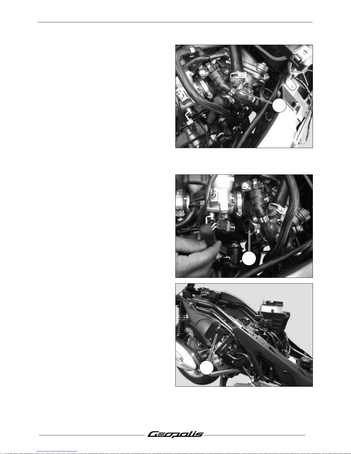
Removal of the thermostat
- Remove the storage compartment. See:
Procedure 1. page 18.
- Disconnect the battery.
- Remove the screw that secures the wiring
harness clamp and the fuel hose anchor
bracket.
- Disconnect the lower pump from the coolant
pump to drain the cooling system.
- Remove the top (1) from the thermostat (2
screws) without disconnecting the hose.
- Remove the thermostat.
Note: After refitting, bleed the engine cir-
cuit hot and check the coolant level
in the header tank. (Peugeot approved coolant).
Removal of the temperature sensor
- Remove the storage compartment. See:
Procedure 1. page 18.
- Disconnect the battery.
- Remove the screw that secures the wiring
harness clamp and the fuel hose anchor
bracket.
- Disconnect the temperature sensor. (1)
- Remove the engine temperature sensor.
Note: After refitting, bleed the engine cir-
cuit hot and check the coolant level
in the header tank.
Removal of the regulator
- Remove the tank cover panel. See:
Procedure 3. page 19.
- Remove the RH fairing. See: Procedure 2.
page 18.
- Disconnect and remove the regulator. (1)
1
1
1
Page 40
MISCELLANEOUS OPERATIONS
38
Reproduction ou traduction, même partielle, interdite sans autorisation écrite de Peugeot Motocycles
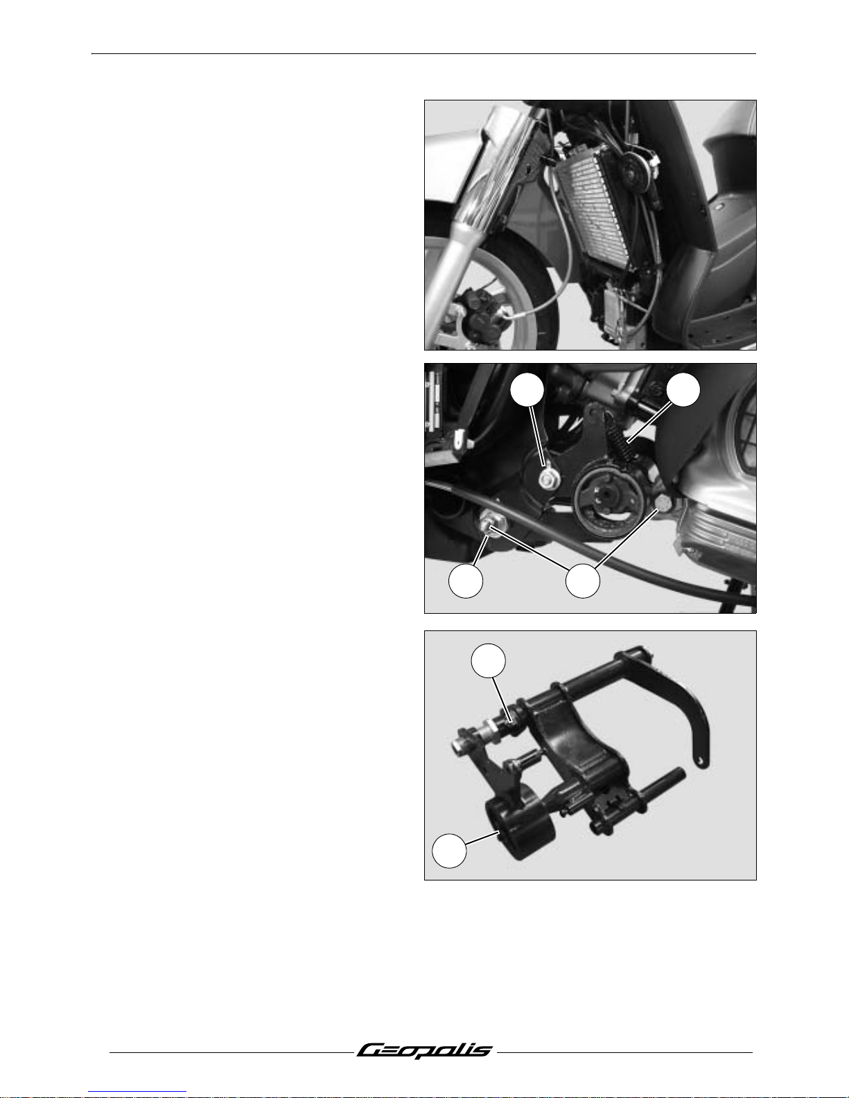
Removal of the radiator
- Remove the tank cover panel. See:
Procedure 3. page 19.
- Disconnect the fan.
- Remove the front shield panel. See:
Procedure 5. page 21.
- Remove the mudguard.
- Remove the upper fixing bolts.
- Drain the cooling circuit.
- Disconnect the 4 hoses of the radiator's
cooling circuit.
- Remove the radiator.
Removal of the engine mounting
assembly
- Remove the side fairings. See:
Procedure 2. page 18.
- Remove the bottom panel.
- Suspend or immobilize the machine
securely.
- Remove the tension spring. (1)
- Remove the adjusting ring locknut. (2)
- Remove the screw that secures the silent
block holder. (3)
- Remove the engine 2 pins securing it to
the frame linkrod and engine linkrod. (4)
- Remove the engine mounting assembly.
- Remove the circlip. (5)
- Remove the linkrod connecting pin. (6)
3
4
1
2
6
5
Page 41
MISCELLANEOUS OPERATIONS
39
Reproduction ou traduction, même partielle, interdite sans autorisation écrite de Peugeot Motocycles
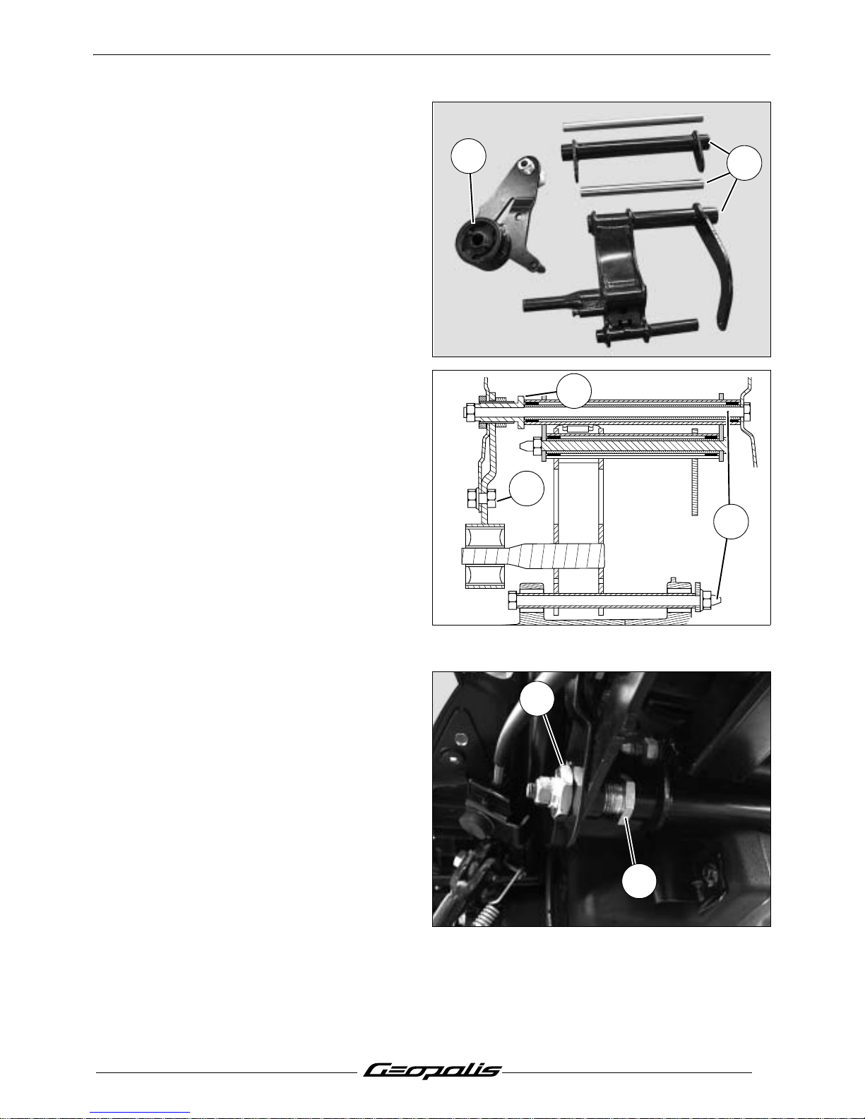
- Check the condition of the spacers and
needle bearings. (7)
- Make sure that the silent block is not
cracked.(8)
Note: We recommend greasing all needle
bearings when refitting these parts.
Installing the engine mounting assembly
- Assemble the engine linkrod assemmbly.
- Fit and tighten the linkrod connecting pin.
Note: Reinstall the pin using standard
thread lock.
Tightening torque: 3.6 m.daN.
- Install the engine mounting assembly in the
frame.
- Fit the 2 pins but do not tighten them. (1)
- Fit screw that secures the silent block
holder.(2)
- Screw but do not tighten the adjusting ring,
so that it comes against the linkrod.(3)
- Tighten the adjusting ring locknut.(4)
Tightening torque: 10 m.daN.
- Tighten the 2 securing pins.
Note: Reinstall the pins using standard
thread lock.
Tightening torque: 5.8 m.daN.
- Tighten the screw that secures the silent
block holder.
Tightening torque: 6.8 m.daN.
Note: When refitting, respect the way the
pins are installed as shown in the
figure.
6
5
8
7
2
1
3
4
3
Page 42
MISCELLANEOUS OPERATIONS
40
Reproduction ou traduction, même partielle, interdite sans autorisation écrite de Peugeot Motocycles
Removal of the cylinder head
Removal of the cylinder / piston
Note: To remove the cylinder head, remove the power propulsion unit.
- Remove the side fairings. See: Procedure 2. page 18.
- Remove the tank cover panel. See: Procedure 3. page 19.
- Carry out the procedure for lowering the pressure in the fuel system. See: Procedure7. page 33.
- Disconnect the 2 fuel injector supply hoses.
- Disconnect the lower pump from the coolant pump to drain the cooling system. (1)
- Disconnect the coolant outlet to the thermostat.
- Disconnect:
• The battery.
• The fuel injector.
• The throttle box.
• The temperature sensor.
• The lambda sensor.
• The magneto.
• The starter motor.
• The suppressor.
- Dieconnect the the throttle control cable from the throttle box.
- Remove the calliper.
- Remove the hydraulic control from its guides on the engine casing.
- Suspend or wedge the machine frame before removing the power unit.
- Remove the shock absorber lower mounts.
- Remove the linkrod-to-engine connecting pin.
- Remove the power propulsion unit from the frame.
Note: For removal of the cylinder head, cylinder and piston, see the workshop manual:
4 stroke engine. 4 valves. Reference: 758850.
Page 43
MISCELLANEOUS OPERATIONS
41
Reproduction ou traduction, même partielle, interdite sans autorisation écrite de Peugeot Motocycles
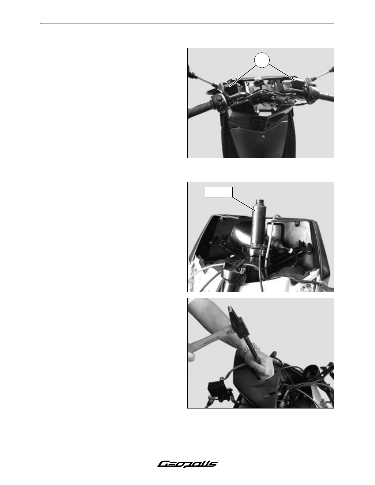
Removal of the fork
Replacing the bearings of the steering
system
- Remove the front top cover panel.
- Remove the handlebar front and rear
covers.
- Remove the 2 upper screws that secure the
rear shield panel.
- Remove the braking units on the
handlebars.(1)
- Remove the handlebars from the fork tube.
- Remove the front mudguard.
- Remove the front brake caliper from the fork
tube.
- Remove the front wheel.
- Using tool P/N 757860 remove the steering
locknut.
- Remove:
• The lock washer.
• the adjustable cone locknut.
• the rubber washer.
• the adjustable cone.
- Remove the fork.
- Remove the balls.
- Using a drift, remove the steering head
cups.
757860
1
757860
Page 44
MISCELLANEOUS OPERATIONS
42
Reproduction ou traduction, même partielle, interdite sans autorisation écrite de Peugeot Motocycles
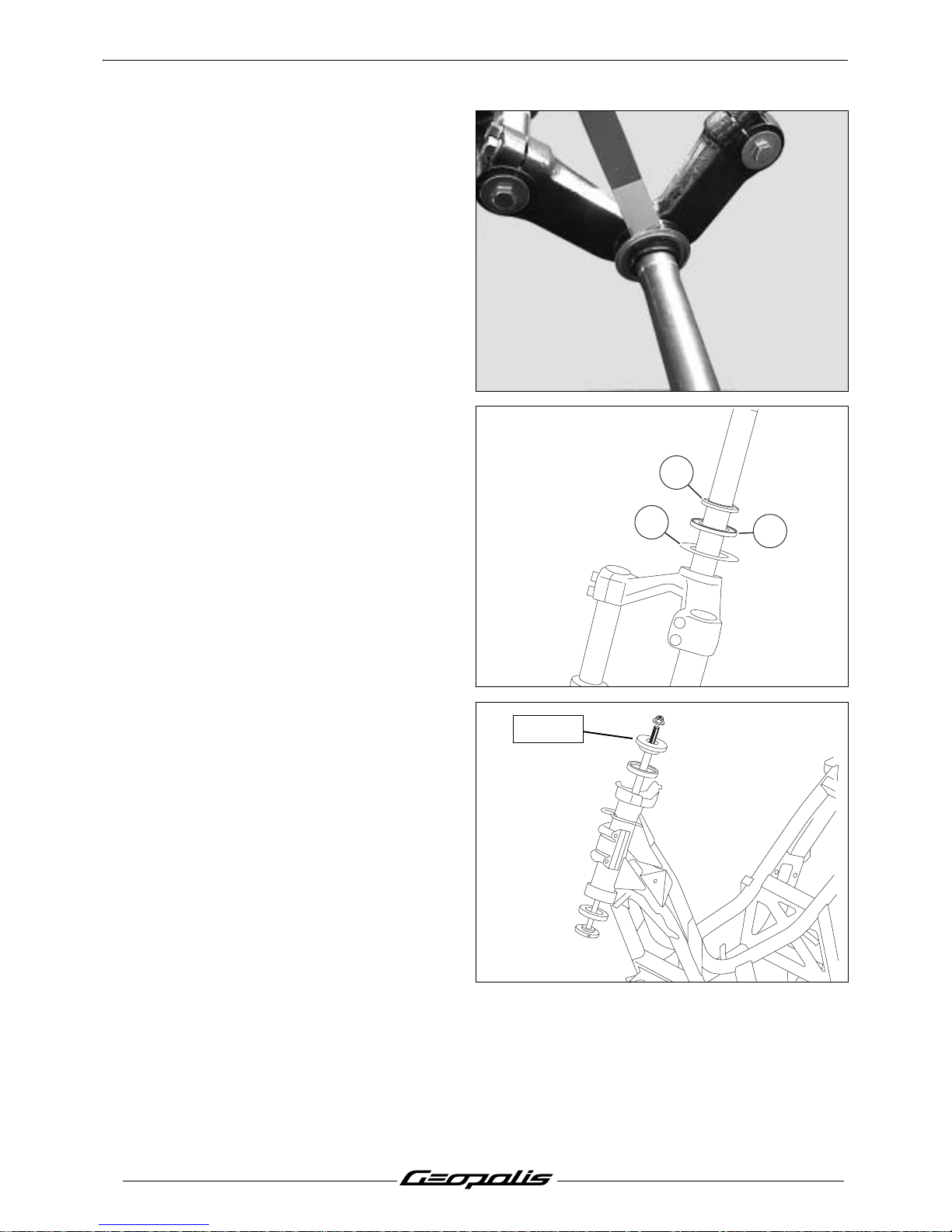
- Using a chisel, pry the steering head cup off
by pressing the tool behind the dust cover.
- Install the following new parts:
• The plain washer. (1)
• The dust cover. (2)
• The fork cone. (3)
- Install new steering head cups using tool
P/N 758810.
3
2
1
758810
Page 45
MISCELLANEOUS OPERATIONS
43
Reproduction ou traduction, même partielle, interdite sans autorisation écrite de Peugeot Motocycles
Steering system tightening method
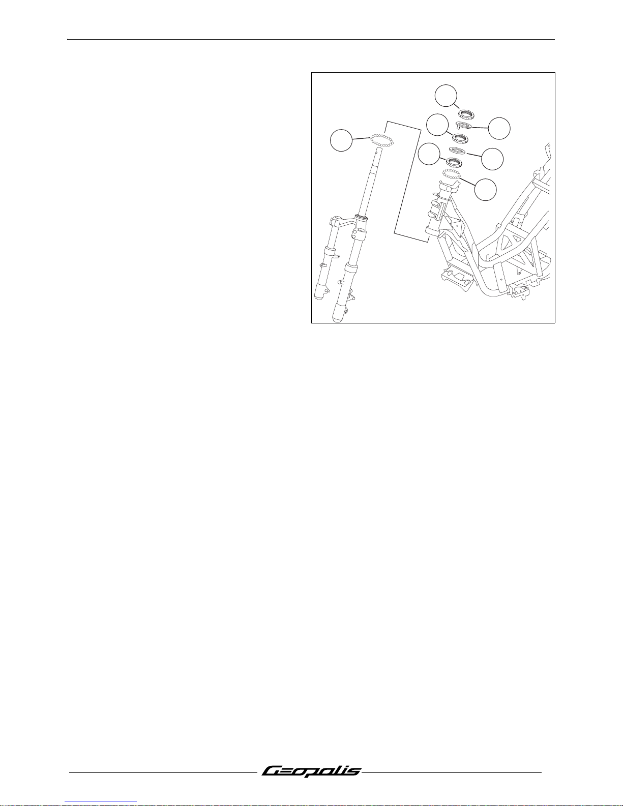
- Grease the cup bearing races.
- Fit the caged ball bearing. (1 and 2).
- Fit the fork into the steering column.
- Install the adjustable cone and tighten it. (3)
Tightening torque: 4 m.daN.
- Loosen and then retighten the adjustable
cone.
Tightening torque: 2.2 m.daN.
- Install the rubber washer. (4)
- Finger tighten the adjustable cone
locknut (5) so that its notches are aligned
with those of the adjustable cone.
- Fit the lock washer (6) in the notches of the
locknut and adjustable cone.
- Install the steering head locknut and tighten
it. (7)
Tightening torque: 7.5 m.daN.
2
1
4
6
5
7
3
Page 46
MISCELLANEOUS OPERATIONS
44
Reproduction ou traduction, même partielle, interdite sans autorisation écrite de Peugeot Motocycles
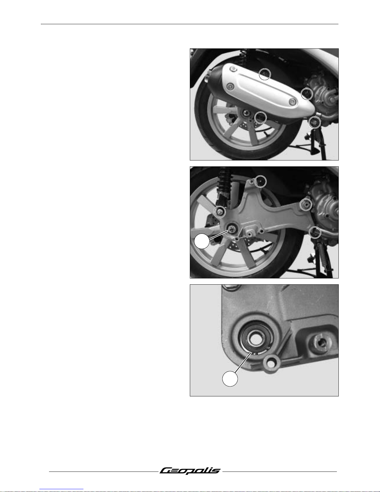
Removal of the suspension arm
- Remove the exhaust. (1 collar and
3screws)
- Remove the pin, the nut retainer and the
wheel nut. (1)
- Remove the suspension arm (3 screws and
1 nut).
- Remove the circlip. (2)
- Using a drift, remove the bearing.
1
2
Page 47
MISCELLANEOUS OPERATIONS
45
Reproduction ou traduction, même partielle, interdite sans autorisation écrite de Peugeot Motocycles
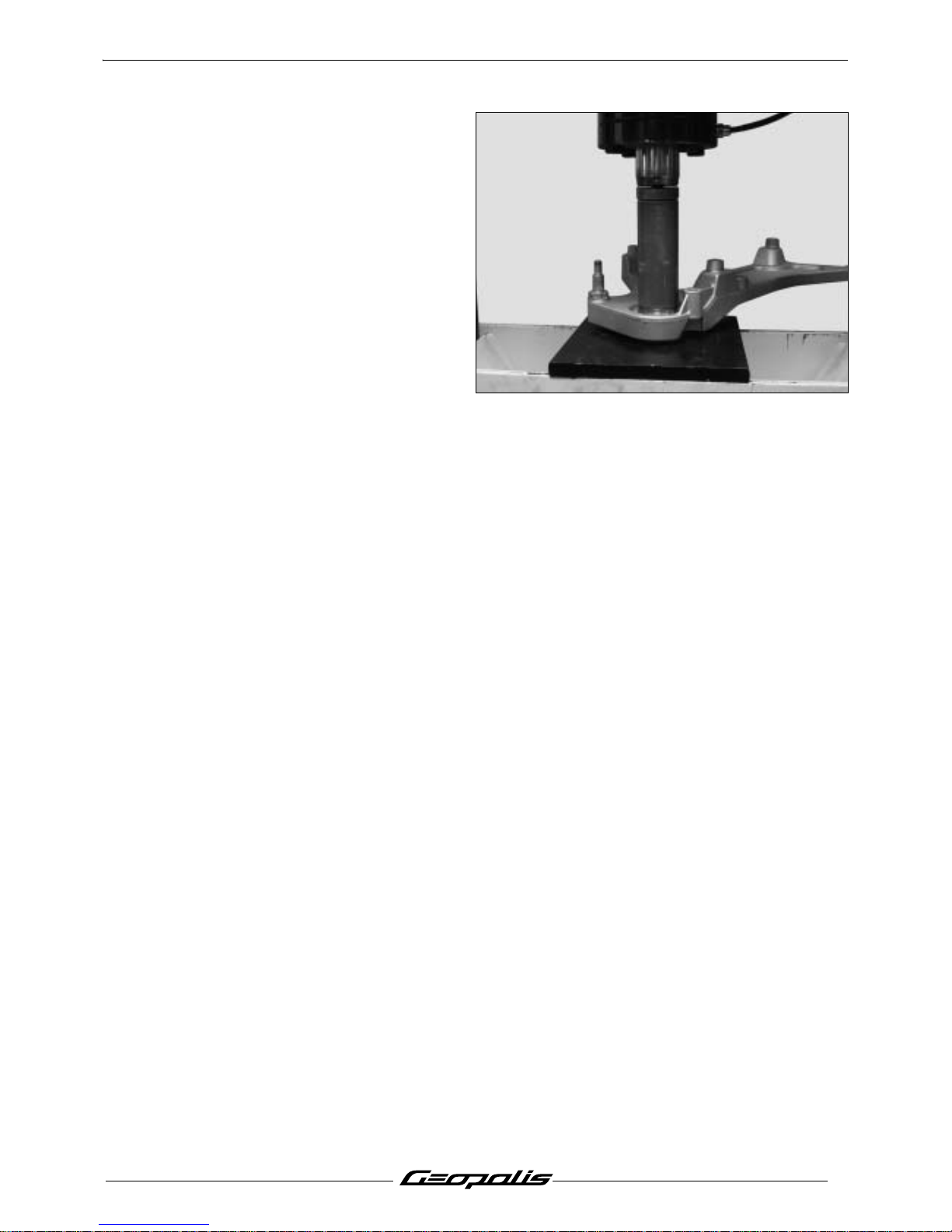
- Using a press and a drift driver, place a new
bearing in the suspension arm, by pushing
against the outer cage of the bearing.
- Install the circlips.
Page 48
MISCELLANEOUS OPERATIONS
46
Reproduction ou traduction, même partielle, interdite sans autorisation écrite de Peugeot Motocycles
Page 49
MISCELLANEOUS OPERATIONS
47
Reproduction ou traduction, même partielle, interdite sans autorisation écrite de Peugeot Motocycles
Page 50

Page 51

Page 52
P/N. 758915
Dans un souci constant d'amélioration Peugeot Motocycles se réserve le droit de supprimer, modifier, ou ajouter
toutes références citées.
DC/PS/APV Imprimé en E.U. 11/2006 (photos non contractuelles)
 Loading...