

Page 1

Quality department
After-Sales
WORKSHOP MANUAL
-
Page 2

TABLE OF CONTENTS
1
Reproduction or translation, even partial, is forbidden without the written consent of Peugeot Scooters
TABLE OF CONTENTS
TABLE OF CONTENTS.....................................................................................................................................1
PRODUCTS DANGER SYMBOLS USED.........................................................................................................4
CHARACTERISTICS.........................................................................................................................................6
Engine........................................................................................................................................................6
Capacities ..................................................................................................................................................6
Chassis ......................................................................................................................................................7
Dimensions and weight..............................................................................................................................7
Tyres ..........................................................................................................................................................7
Brakes........................................................................................................................................................8
SERVICE SCHEDULE AND COMMISSIONING...............................................................................................9
Battery preparation ..................................................................................................................................10
Installing the battery.................................................................................................................................11
New machine preparation........................................................................................................................11
Electricity..................................................................................................................................................11
SPECIAL IMPORTANT POINTS .....................................................................................................................12
TIGHTENING TORQUES ................................................................................................................................13
Engine part...............................................................................................................................................13
Body panels.............................................................................................................................................13
Cycle part.................................................................................................................................................14
Standard...................................................................................................................................................14
SPECIAL TOOLS ............................................................................................................................................15
STANDARD TOOLS........................................................................................................................................16
LOCATION OF COMPONENTS......................................................................................................................17
BODY PANELS ...............................................................................................................................................18
Location of body components..................................................................................................................18
Description...............................................................................................................................................18
Body component sequence of disassembly.............................................................................................19
Removal of the passenger's saddle.........................................................................................................20
Removal of the storage compartment......................................................................................................20
Removal of the battery holder..................................................................................................................20
Remove the central fairing under the saddle ...........................................................................................21
Removal of the central cover panel..........................................................................................................21
Removal of a lower RH or LH side fairing................................................................................................21
Page 3

TABLE OF CONTENTS
2
Reproduction or translation, even partial, is forbidden without the written consent of Peugeot Scooters
Removal of the grab handles...................................................................................................................22
Removal of the upper side fairing assembly............................................................................................23
Removal of the upper side fairing assembly............................................................................................23
Removal of the front shield panel.............................................................................................................23
Removal of the head light fairing .............................................................................................................25
Removal of the speedometer fairing........................................................................................................26
Removal of the footboard.........................................................................................................................26
Removal of the rear shield panel .............................................................................................................27
Removal of the door-locking system........................................................................................................27
Removal of a RH or LH door....................................................................................................................28
Removal of the RH or LH under body panel............................................................................................28
Removal of the front mudguard ...............................................................................................................29
Removal of the dirt shield ........................................................................................................................30
SERVICE OPERATIONS.................................................................................................................................31
Empty the oil from the engine..................................................................................................................31
Draining the relay box..............................................................................................................................32
Replacing the air filter with transmission maintenance .....................................................................................33
Reassembly....................................................................................................................................................... 33
Replacing the air filter without transmission maintenance ................................................................................33
Reassembly....................................................................................................................................................... 34
Removal of the spark plug.......................................................................................................................34
Idle setting................................................................................................................................................35
Removal of the primary transmission cover.............................................................................................36
Removal of the starter system...........................................................................................................................36
Fitting the starter system...................................................................................................................................38
Removal of the transmission air filter ................................................................................................................38
Removal of the drive pulley......................................................................................................................39
Removal of the driven pulley....................................................................................................................39
Changing the drive pulley bearings..........................................................................................................40
Checking the drive belt ............................................................................................................................40
Checking the thickness of the clutch linings ............................................................................................41
Removal of the clutch lining assembly.....................................................................................................41
Refitting the clutch lining assembly..........................................................................................................42
Installing the primary drive.......................................................................................................................43
Installing the valve clearance...................................................................................................................44
Checking the valve clearance..................................................................................................................46
Changing the fuel filter.............................................................................................................................46
Integral braking ........................................................................................................................................47
Brake pad wear........................................................................................................................................47
Front brake........................................................................................................................................................47
Rear brake......................................................................................................................................................... 48
Page 4

TABLE OF CONTENTS
3
Reproduction or translation, even partial, is forbidden without the written consent of Peugeot Scooters
Replacing the brake pads........................................................................................................................48
Front brake........................................................................................................................................................48
Rear brake......................................................................................................................................................... 49
Bleeding the integral circuit......................................................................................................................50
Draining the main brake circuit..........................................................................................................................50
Bleeding the emergency system......................................................................................................52
Conventional braking ...............................................................................................................................54
Brake pad wear........................................................................................................................................54
Front brake........................................................................................................................................................54
Rear brake......................................................................................................................................................... 55
Replacing the brake pads........................................................................................................................55
Front brake........................................................................................................................................................55
Rear brake......................................................................................................................................................... 56
Draining the rear brake circuit:.........................................................................................................57
Draining the front brake circuit:........................................................................................................58
Checking the brake fluid level..................................................................................................................59
Draining the front fork ..............................................................................................................................60
STEERING/FORK............................................................................................................................................61
Changing the front fork seals...................................................................................................................61
The fork and its components.............................................................................................................................64
Reassembly....................................................................................................................................................... 65
Removal of the fork..................................................................................................................................67
Replacing the bearings of the steering system........................................................................................69
Steering headset cups.......................................................................................................................................69
Steering cone ....................................................................................................................................................70
Installing the fork......................................................................................................................................70
FUEL SYSTEM ................................................................................................................................................72
Removal of the fuel gauge.......................................................................................................................72
Fuel gauge check.....................................................................................................................................72
Removal of the fuel pump........................................................................................................................72
ELECTRICITY..................................................................................................................................................74
Ignition principle schematic/Carburetor heater/Battery charge circuit......................................................74
Regulator/Temperature control unit/Starter motor relay/CDI unit/Starter resistor.....................................75
Checking the ignition system...................................................................................................................75
Checking the carburettor heating circuit ..................................................................................................76
Checking the starter circuit.......................................................................................................................76
Checking the indicators............................................................................................................................77
Checking the red light, the stop light and the side light............................................................................77
POWER UNIT ..................................................................................................................................................78
Removal of the power unit.......................................................................................................................78
Page 5
PRODUCTS DANGER SYMBOLS USED
4
Reproduction or translation, even partial, is forbidden without the written consent of Peugeot Scooters
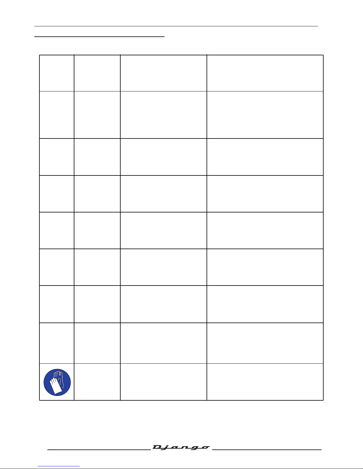
PRODUCTS DANGER SYMBOLS USED
Protection of individuals and of the environment.
Möbius band Recyclable.
Means that the product or the package
can be recycled. However, this does not
guarantee that the product will be
recycled.
Irritant
The product can irritate the
skin, eyes and respiratory
organs.
Avoid contact with skin and clothes. Wear
gloves, safety goggles and cotton
overalls.. Do not breath fumes. If in
contact, wash thoroughly with water.
Flammable The product is flammable.
Keep it away from flames or any heat
source (barbecue, radiator, heating, etc.).
Do not leave the product in the sun.
Corrosive
The product can damage living
tissues or other surfaces.
Avoid contact with skin and clothes. Wear
gloves, safety goggles and cotton
overalls.. Do not breath fumes.
Explosive
The product can explode under
certain circumstances (flame,
heat, impact, friction).
Avoid impacts, friction, sparks and heat.
Hazardous to
the environment
The product affects fauna and
flora. Do not dump it in
dustbins, sinks or in the
environment.
The ideal solution is to bring this product
to your nearest household waste recycling
centre.
Toxic
The product can seriously
affect health if it is inhaled,
ingested or in contact with skin.
Avoid direct contact with the body, even by
inhalation. If you feel unwell, seek medical
advice immediately.
Do not throw
away into a
garbage can
One of the product's
component is toxic and can be
hazardous to environment.
Example: Used batteries.
This symbol informs the consumer that the
used product shall not be thrown away into
a garbage can, but shall be brought back
to the merchant or dropped at a specific
collection point.
Compulsory
gloves
Operation that can be
dangerous for people.
People's safety can be seriously affected if
the recommendations are not fully
respected.
Page 6
PRODUCTS DANGER SYMBOLS USED
5
Reproduction or translation, even partial, is forbidden without the written consent of Peugeot Scooters
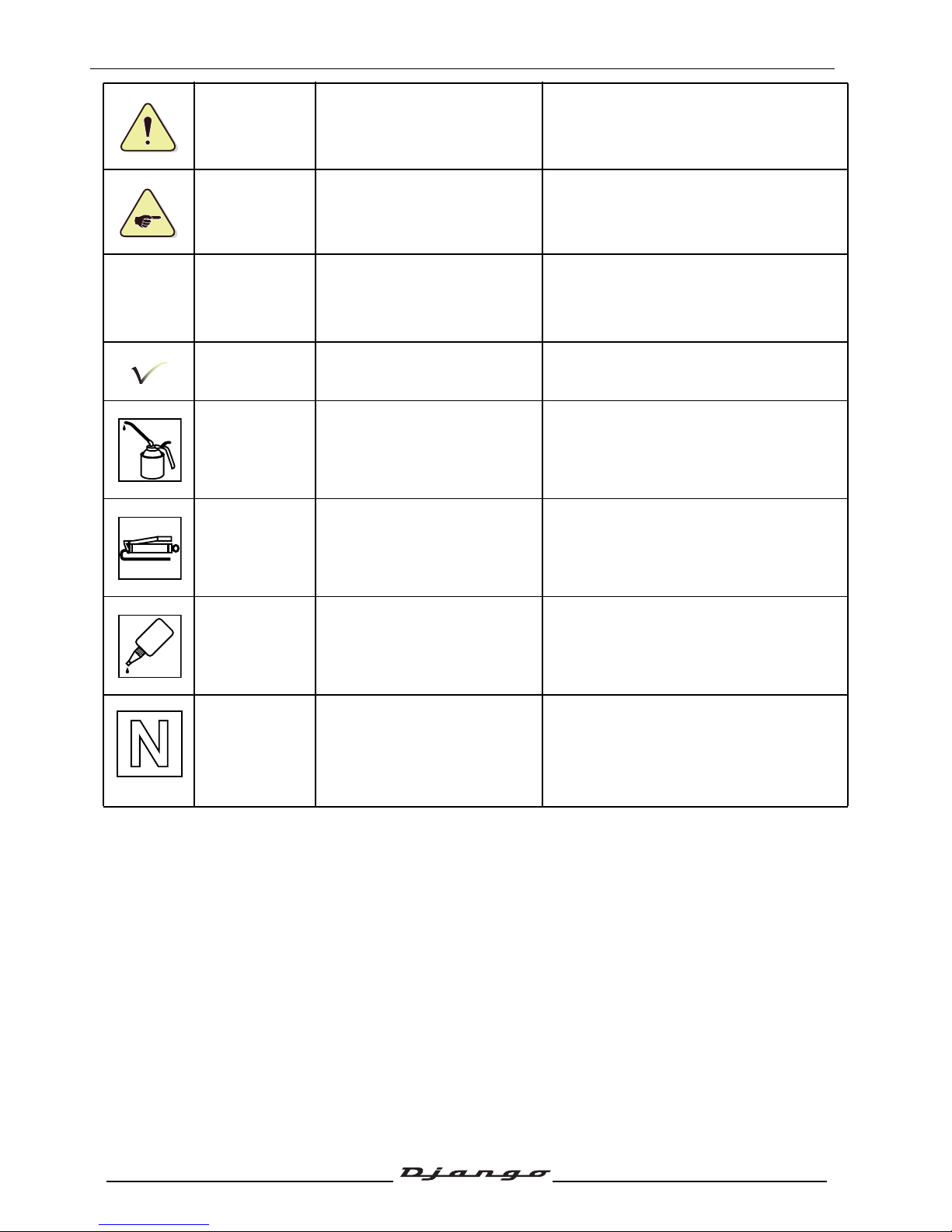
People's safety
Operation that can be
dangerous for people.
People's safety can be seriously affected if
the recommendations are not fully
respected.
Important
Operation that can be
hazardous to the vehicle.
Indicate the specific procedures that shall
be followed in order not to damage the
vehicle.
Good operating
condition of the
vehicle
The operation must be carried
out in strict compliance with the
documents.
Serious damage to the vehicle and in
certain cases a cancellation of the
warranty can be involved if the
recommendations are not fully respected.
Note Operation that can be difficult.
Indicate a note which gives key
information to make the procedure easier.
Lubricate
Lubricate the parts to be
assembled.
Indicate the specific procedures that shall
be followed in order not to damage the
vehicle.
Grease
Grease the parts to be
assembled.
Indicate the specific procedures that shall
be followed in order not to damage the
vehicle.
Glue
Glue the parts to be
assembled.
Indicate the specific procedures that shall
be followed in order not to damage the
vehicle.
New part Use a new part.
Indicate the specific procedures that shall
be followed in order not to damage the
vehicle.
GLUE
Page 7
CHARACTERISTICS
6
Reproduction or translation, even partial, is forbidden without the written consent of Peugeot Scooters
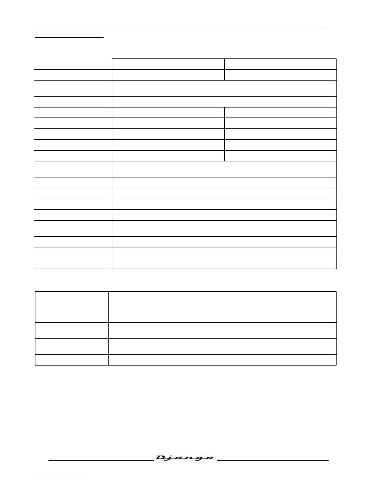
CHARACTERISTICS
Engine
Capacities
125 cc 150 cc
Marking XS1P52QMI-3B XS1P57QMJ-2B
Type
4-stroke single-cylinder
4 valves per cylinder with chain driven overhead camshaft
Cooling By a circulation of forced air by means of a turbine on the flywheel magneto
Bore x stroke 52.4 x 57.8 mm 57.4 x 58.2 mm
Cubic capacity 124.6 cc 150.6 cc
Max. power output 7.5 kW at 8500 rpm 8.3 kW at 8000 rpm
Max. torque rating 8.9 Nm at 7000 rpm 11 Nm at 6000 rpm
Compression
Compression ratio 10,6
±0.2
:1 Compression ratio 10,4
±0.2
:1
Compression ratio
11.4 bars at 700 rpm
7 bars Minimum.
Lubrication Trochoid pump driven by a chain from the crankshaft
Transmission By 2 variable pulleys and V-type belt
Clutch Centrifugal automatic
Exhaust Catalytic
Spark plug
NGK CR7HSA
Electrode gap: 0.7 - 0.8 mm
Magneto flywheel 80W
Fuel supply Deni DPD24J carburettor
Standards Euro3
Crankcase
0.95 L
(0.7 L at oïl change)
SAE 5W40 Synthetic
Minimum grade: API SJ
Relay box
0.18 L SAE 80W90 (0.17 L at oïl change)
Minimum grade: API GL4
Fuel tank
8.5 L
Unleaded 95 or 98
Fork oil 0.092 L per tube SAE 10W.
Page 8
CHARACTERISTICS
7
Reproduction or translation, even partial, is forbidden without the written consent of Peugeot Scooters
Chassis
Dimensions and weight
Tyres
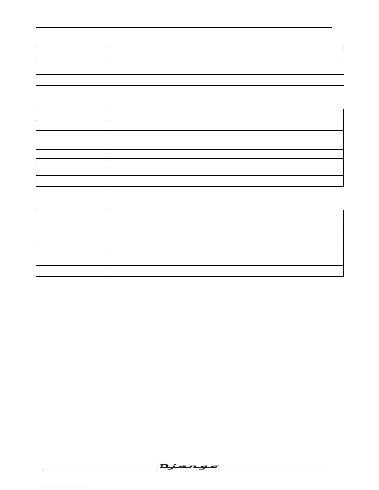
Chassis Steel tube
Front suspension
32 mm Ø telescopic front fork
Travel: 85 mm
Rear suspension Combined spring and hydraulically-damped shock absorber Travel: 88 mm
Overall length
1925 mm
Width at handlebar
710 mm
Height. (without rear-
view mirrors)
1190 mm
Wheelbase 1350 mm
Ground clearance 110 mm
Saddle height 770 mm
Unladen weight
129 kg
Front wheel rims 3"x12 inch aluminium alloy
Front tyre 120/70 - 12
Front tyre pressure 1.8 bars
Rear wheel rim 3"x12 inch aluminium alloy
Rear tyre 120/70 - 12
Rear tyre pressure 2 bars
Page 9
CHARACTERISTICS
8
Reproduction or translation, even partial, is forbidden without the written consent of Peugeot Scooters
Brakes
Version Conventional braking Integral braking
Front brake Single disc type, hydraulic control
Disc diameter and
thickness
200 mm - 3.5 mm
Mini. thickness: 3 mm
Front caliper
Floating calliper equipped with
2 pistons
Floating calliper equipped with
3 pistons
Rear brake Single disc type, hydraulic control
Disc diameter and
thickness
196 mm - 4 mm
Mini. thickness: 3.5 mm
190 mm - 4 mm
Mini. thickness: 3.5 mm
Rear caliper Fixed calliper with 2 pistons
Floating caliper equipped with one
piston
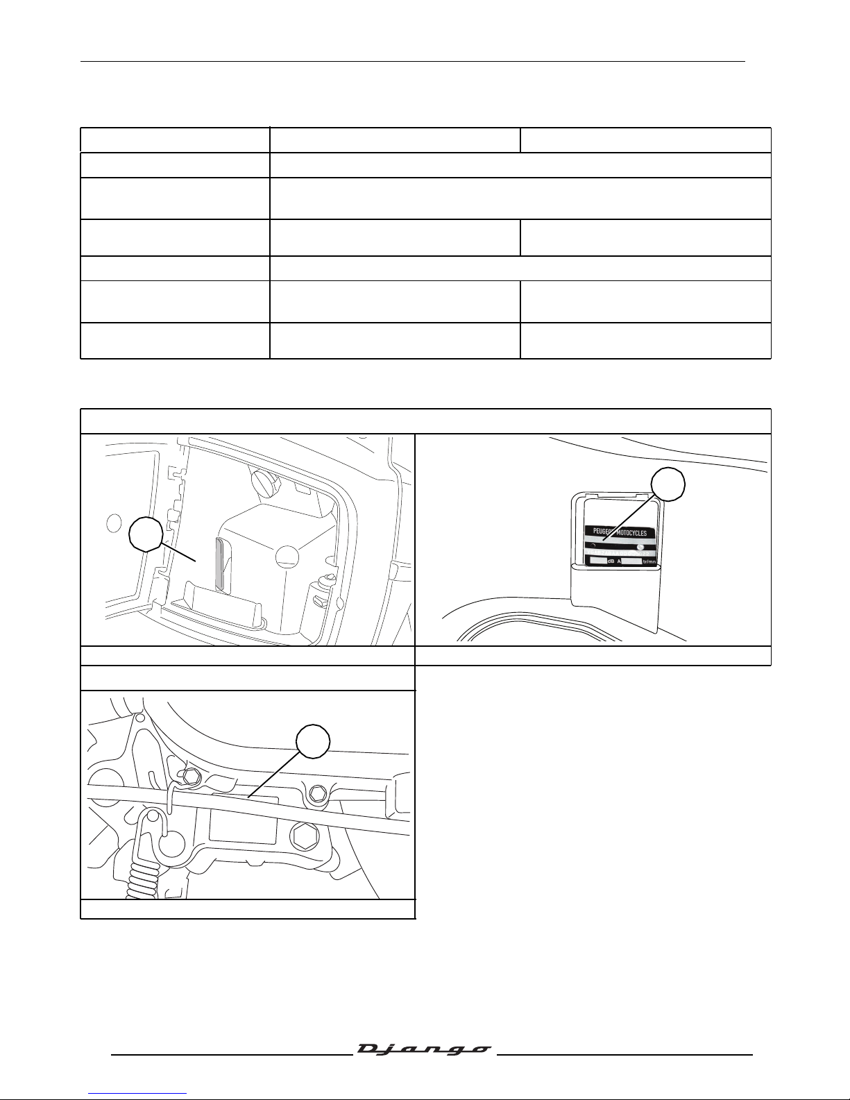
Chassis markings
1. VIN number 2. Manufacturer's plate
Engine marking
3. Engine number
xxxxxxxxxxxxxxxx
1
2
XXXXXX
*XXXXXXX
XX
*
3
Page 10
SERVICE SCHEDULE AND COMMISSIONING
9
Reproduction or translation, even partial, is forbidden without the written consent of Peugeot Scooters
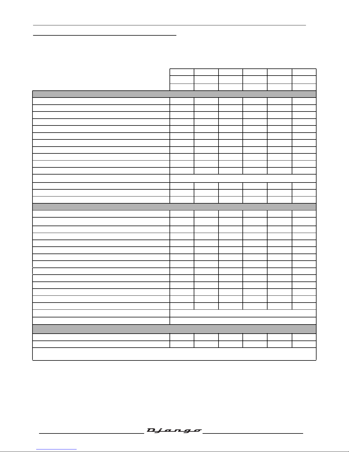
SERVICE SCHEDULE AND COMMISSIONING
Heavy duty servicing is for vehicles used under "harsh" conditions: door-to-door deliveries, intensive
urban use (courier), short journeys with engine cold, dusty areas, ambient temperature over 30°C.
Normal servicing in km 500 5000 10000 15000 20000 25000
Extensive servicing in km
a
a.Perform these maintenance operations if the vehicle is used in severe conditions: areas that are damp, dusty, or have high
températures, urban use only, etc
500 2500 5000 7500 10000 12500
Minimum servicing
1months 12months 24months 36months 48months 60months
To be checked at each service
Steering column play. V V V V V V
Wheel bearing play. C C C C C C
Throttle cable play. V V V V V V
Operation of electrical equipment. V V V V V V
Condition of front and rear brake hydraulic controls. V V V V V V
Brake fluid level. V V V V V V
Brake pad wear. C C C C C C
Condition of petrol pipes. C C C C C C
Tyre condition, pressure and wear. C C C C C C
Condition of the front suspension. Condition of the rear suspension.
V V V V V V
Battery charge. V V V V V V
Engine oil level.
Every 1000 km
Headlight height adjustment. V V V V V V
Tightness of nuts and bolts. V V V V V V
Overall operation. Road test. V V V V V V
Service operations
Spark plug. R R
Air filter.
R
a
R
R
a
R
R
a
Intake silencer drain. N N N N N
Drive pulley rollers and guides/Flange wear. C C
Driven pulley caged needle bearing. G G
Transmission belt. R R
Kick starter mechanism. G G
Valve clearances. V V V V V
Setting the carburettor. V V
Joints. (Central stand. Lateral stand) G G G G G
Petrol filter. R
Engine oil (+ clean strainer). R R R R R R
Relay box oil. R R R R R R
Fork oil. R
Petrol pipe.
R Once every 5 years
Brake fluid.
R Once every 2 years
Servicing time in tenths of an hour (0.5 h = 30 min)
Reception and Treatment 0.1 0.1 0.1 0.1 0.1 0.1
Django 125/150cc 0.9 1.9 2.3 1.9 3.3 1.9
V: Check, clean, adjust. R: Change. G: Check, clean, lubricate. C: Inspect and change if necessary. N: Clean.
After 20000 km, resume the service schedule again from 5000 km.
Page 11
SERVICE SCHEDULE AND COMMISSIONING
10
Reproduction or translation, even partial, is forbidden without the written consent of Peugeot Scooters
Battery preparation
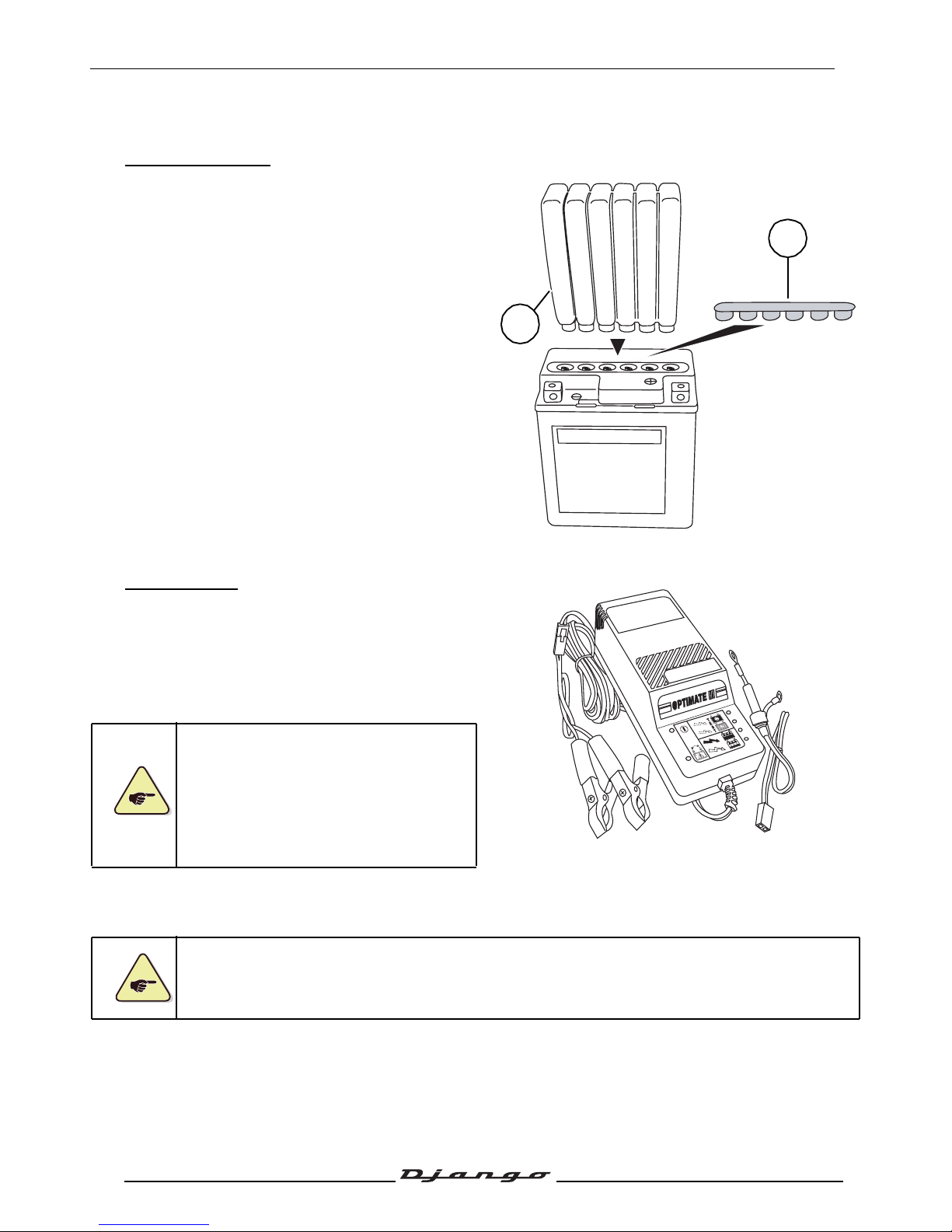
Battery preparation:
- Remove the battery's filler protector.
- Remove the strip of caps (1) from the
electrolyte bottle, which will be used as battery
caps (2).
- Place the electrolyte bottle upside down with
the 6 sealed zones in line with the 6 battery filler
holes.
- Press downwards to pierce the bottle's seal.
- Air bubbles must go up into the bottle.
- Tap on the bottle to help the air bubbles go up.
- Once the battery is filled with electrolyte,
remove the bottle.
- Leave the battery to stand for around half an
hour.
- Fit the strip of caps (1) over the battery's filler
holes.
Battery charge:
Once it is filled with electrolyte, a new battery is
charged up to approximately 80%.
The battery must be charged before being used
for the first time. If it is not charged in this way a
loss of 20% of its maximum nominal capacity and
30% of its life expectance will be permanent.
You must absolutely use a battery
charger provided with a charge regulator
which is suited to small capacities.
See documentation: Workshop tools
N° 2.
The battery's maximum charging
current is equal to 1 tenth of its capacity.
- Charge the battery for 5 to 10 hours.
- Leave the battery to stand for around half an
hour.
Never remove the battery's strip of caps, and never add water or electrolyte into the battery.
2
1
T
E
S
T
Page 12
SERVICE SCHEDULE AND COMMISSIONING
11
Reproduction or translation, even partial, is forbidden without the written consent of Peugeot Scooters
Installing the battery
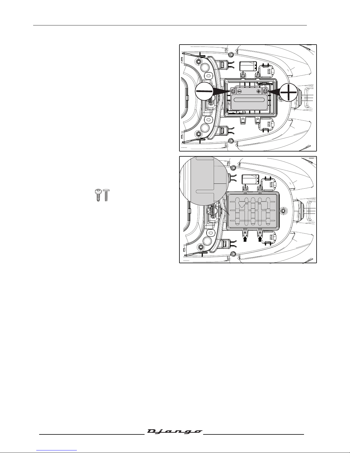
- Fit the battery.
- Connect the red wire lug to the battery's +
terminal, and the green wire lug to the battery's
- terminal.
- Fit the battery cover, ensuring it is the right way
round. The vehicle's cubic capacity must be
visible from the outside.
- 2 plastic screws.
New machine preparation
- See the new vehicle preparation sheet.
- Check the wheel nuts are tight.
- Check nuts and bolts are tight.
- Check brake adjustment and efficiency.
- Check the tyre pressures cold.
- Check operation of the lights, flashers, horn, and brake light.
- Check the different warning lights work.
- Carry out a road test.
Electricity
All components of the electrical system are powered with 12 volts DC.
The battery must not be disconnected while the engine is running and the voltage must be at least
8.5 volts for the ECU to function and enable engine starting.
125/151CC
125/151CC
Page 13
SPECIAL IMPORTANT POINTS
12
Reproduction or translation, even partial, is forbidden without the written consent of Peugeot Scooters
SPECIAL IMPORTANT POINTS
This engine is designed to run on 95 or 98 unleaded fuel only.
Fuel pipes must absolutely be changed if there are any signs of wear, cracks, etc.
The clips are specific, they must always be changed each time they are removed and replaced
with new genuine parts clips.
Petrol is highly inflammable, do not smoke in the working area and avoid proximity to flames or
sparks.
Before carrying out any work, leave the engine to cool for at least 2 hours.
Page 14
TIGHTENING TORQUES
13
Reproduction or translation, even partial, is forbidden without the written consent of Peugeot Scooters
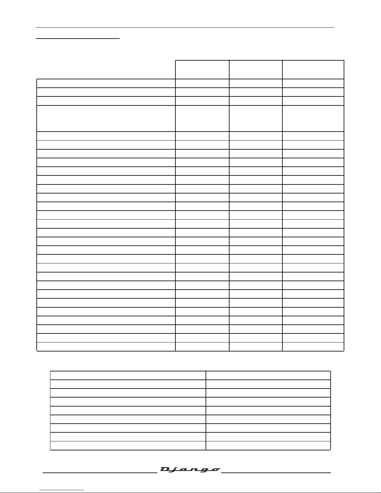
TIGHTENING TORQUES
Engine part
Body panels
Quantity Dimension
Tightening torque
125/151 cc
Spark plug 1 M10-1.5 10 to 12 Nm
Engine drain plug 1 M12 35 to 45 Nm
Screen 1 M30 10 to 20 Nm
Cylinder head
Nut Ø8 mm
Screw Ø6 mm
4
2
M8-1.25
M6-1.0
18 to 22 Nm
7 to 11 Nm
Cylinder head cover 4 M6-1.0 8 to 12 Nm
Camshaft gear 2 M6-1.0 10 to 15 Nm
Camshaft stopper plate 1 M6-1.0 10 to 15Nm
Automatic tensioner 2 M5-0.8 7 to 11 Nm
Automatic tensioner plug 2 M6-1.0 8 to 12 Nm
Camshaft gear 1 M6-1.0 8 to 12 Nm
Chain tensioner 1 M6-1.0 8 to 12 Nm
Inlet manifold 2 M6-1.0 8 to 12 Nm
Cylinder casings 2 M6-1.0 8 to 12 Nm
RH casing cover 10 M6-1.0 7 to 11 Nm
Freewheel 1 M22 90 to 100 Nm
Oil pump 2 M6-1.0 8 to 12 Nm
Anti-splash plate 2 M6-1.0 8 to 12 Nm
Transmission cover 8 M6-1.0 8 to 12 Nm
Relay box cover 7 M8-1.25 26 to 30Nm
Relay box drain plug 1 M8-1.25 10 to 15Nm
Relay box filler cap 1 M8-1.25 10 to 15Nm
Starter motor 2 M6-1.0 7 to 11 Nm
Rotor 1 M12 50 to 60Nm
Turbine 4 M6-1.0 8 to 12 Nm
Stator 2 M6-1.0 8 to 12 Nm
Engine speed sensor 2 M5-0.8 4 to 6 Nm
Drive pulley 1 M12 55 to 60 Nm
Driven pulley 1 M12 50 to 60Nm
Clutch plate and shoes 1 M28 55 to 60 Nm
Front mudguard
8 to 10 Nm
Handlebar cover
1 to 2 Nm
Front shield panels
1 to 2 Nm
Rear shield
1 to 2 Nm
Bottom panel
6 to 8 Nm
Floor panel
8 to 10 Nm
Saddle storage compartment
8 to 10 Nm
Rear body panels
1 to 2 Nm
Grab handle
20 to 25 Nm
Page 15
TIGHTENING TORQUES
14
Reproduction or translation, even partial, is forbidden without the written consent of Peugeot Scooters
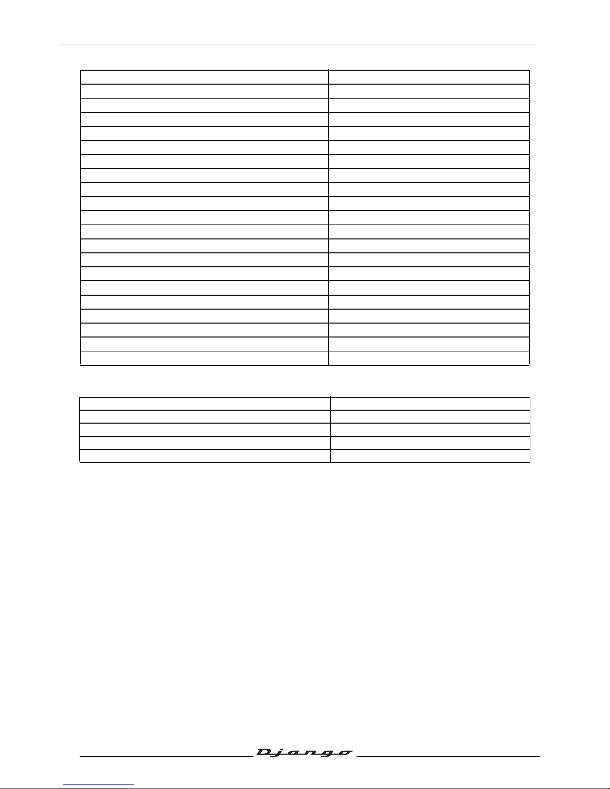
Cycle part
Standard
Front wheel spindle
60 to 70 Nm
Wheel hub pin
100 to 120 Nm
Rear wheel bolt
27 to 32 Nm
Engine/linkrod connecting pin
52 to 62 Nm
Linkrod/chassis connecting pin
52 to 62 Nm
Shock absorber top mount
43 to 50 Nm
Shock absorber bottom mount
20 to 25 Nm
Exhaust to cylinder head mounting nut
20 to 25 Nm
Exhaust to casing mounting bolt
20 to 25 Nm
Steering nut 1 (in 2 operations)
38 to 42 Nm/15 to 19Nm
Steering nut2
Hand tightened
Steering locknut
70 to 85 Nm
Front brake caliper
27 to 32 Nm
Brake pad pins
12 to 18 Nm
Front brake disc
27 to 32 Nm
Rear brake caliper
27 to 32 Nm
Rear brake disc
27 to 32 Nm
Brake unions
27 to 35 Nm
Handle bar
35 to 45 Nm
Fork tube
25 to 30 Nm
Fork tube cap
25 to 30 Nm
Nut and bolt 5 mm diameter 5Nm
Nut and bolt 6 mm diameter 10 Nm
Nut and bolt 8 mm diameter 22 Nm
Nut and bolt 10 mm diameter 35 Nm
Nut and bolt 12 mm diameter 55 Nm
Page 16
SPECIAL TOOLS
15
Reproduction or translation, even partial, is forbidden without the written consent of Peugeot Scooters
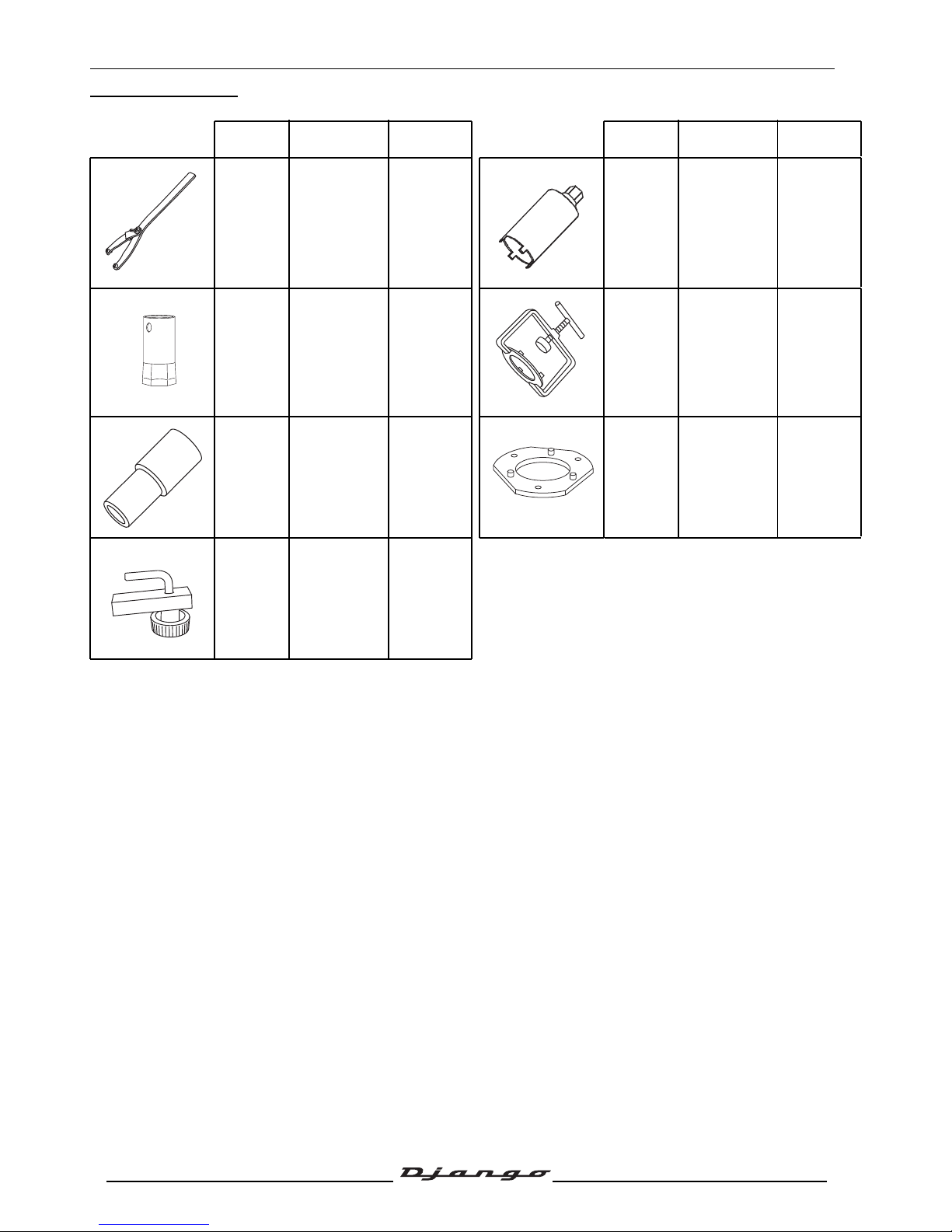
SPECIAL TOOLS
(*) New or modified tool
Tool N° Designation Used with Tool N° Designation Used with
752237
Adjustable
pin wrench
757860 Steering tool
752361
39 mm pipe
casing seal
drift
758008
Clutch
compression
tool
801682
759788
Steeing head
cup push tool
801682
Spacer
adaptor
758008
755996 Hose clamp
Page 17
STANDARD TOOLS
16
Reproduction or translation, even partial, is forbidden without the written consent of Peugeot Scooters
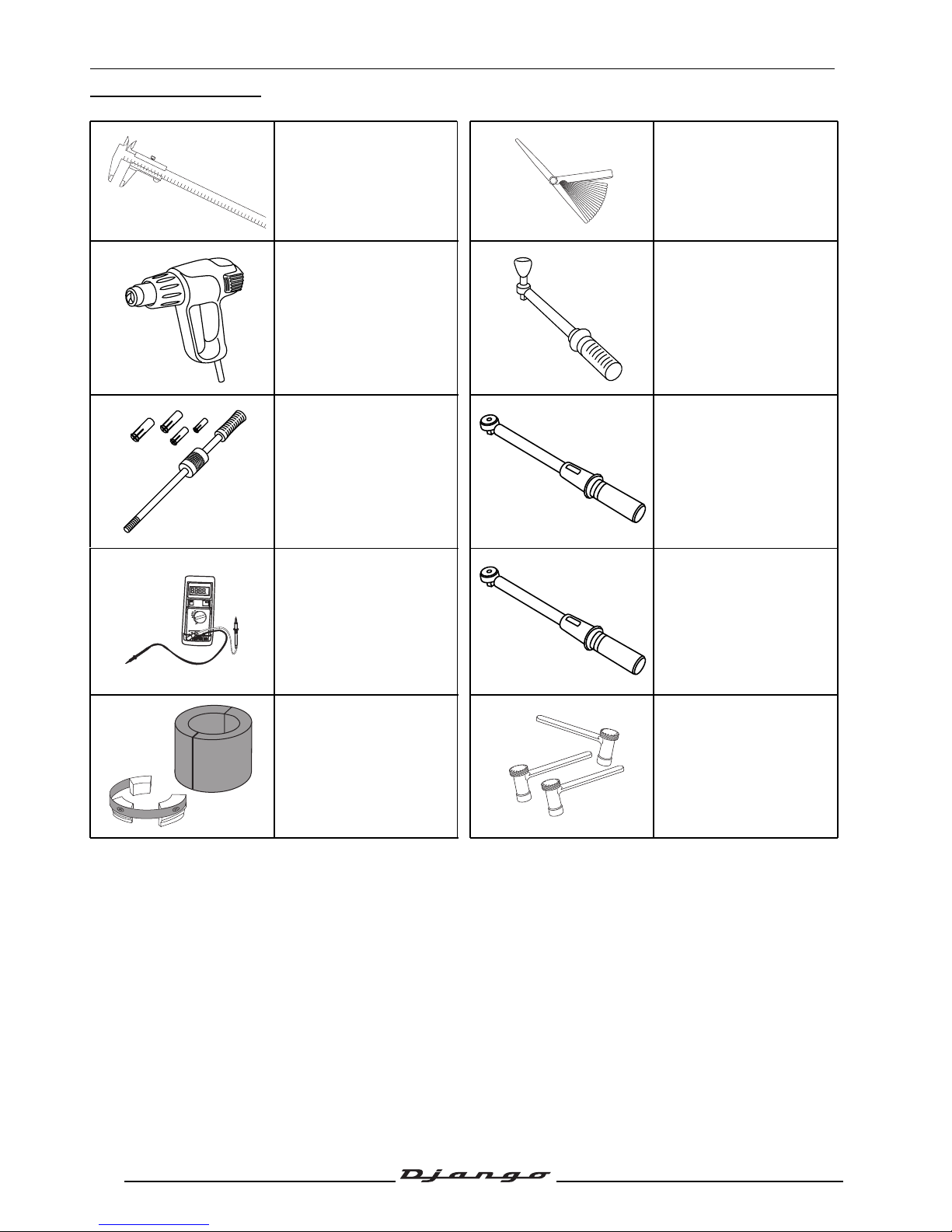
STANDARD TOOLS
Slide calipers Set of shims
Heat gun
Automatic resetting type
torque wrench
5 to 25 Nm
Type: Facom R.306A25
Intertia type extractor
tool for bearings from
6 to 18 mm
Type: Facom U.49PJ3
Automatic resetting type
torque wrench
10 to 50 Nm
Type: Facom J.208A50
Multimeter
Automatic resetting type
torque wrench
40 to 200 Nm
Type: Facom S.208A200
Fork seal insertion kit
Type: Marolotest 601055
Wrenches with
interchangeable end
fittings for valve
clearance adjustment
Type: Marolotest 500140
OFF
VDC
VAC
Ω
20 m
200 m
DC
10A
V
Ω
COM
mA
Ω
Page 18
LOCATION OF COMPONENTS
17
Reproduction or translation, even partial, is forbidden without the written consent of Peugeot Scooters
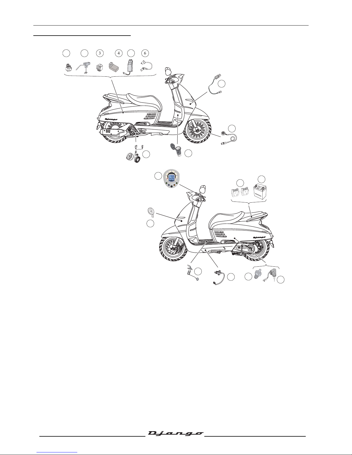
LOCATION OF COMPONENTS
1. Starter motor relay
2. Starter resistor
3. Regulator
4. CDI unit
5. Temperature control unit
6. HT coil
7. Outside temperature sensor
8. Speed sensor
9. 12-volt plug
10.Ignition sensor
11.Instrument panel
12.Fuses
13.Battery
14.Choke
15.Carburetor heater
16.Kickstand contact switch
17.Fuel gauge
18.Horn
FB
X
X
X
X
6
43
7
9
2
10
5
1
8
16
14
17
12
13
15
11
18
Page 19
BODY PANELS
18
Reproduction or translation, even partial, is forbidden without the written consent of Peugeot Scooters
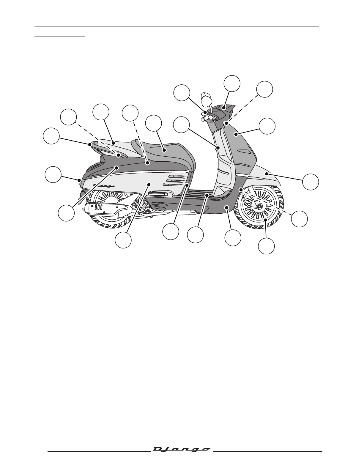
BODY PANELS
Location of body components
Description
1. Front shield panel
2. Front mudguard
3. Mudguard
4. Front wheel
5. Bottom panel
6. Floor panel
7. Central panel
8. Lower side fairing
9. Upper side fairing
10.Rear central fairing
11.Grab handle
12.Battery holder
13.Passenger backseat
14.Saddle storage compartment
15.Rider saddle
16.Rear shield
17.Counter panel
18.Headlight fairing
19.Sheath guide
FB
4
3
7
9
2
10
1
8
13
17
16
11
5
12
14
18
6
15
19
Page 20
BODY PANELS
19
Reproduction or translation, even partial, is forbidden without the written consent of Peugeot Scooters
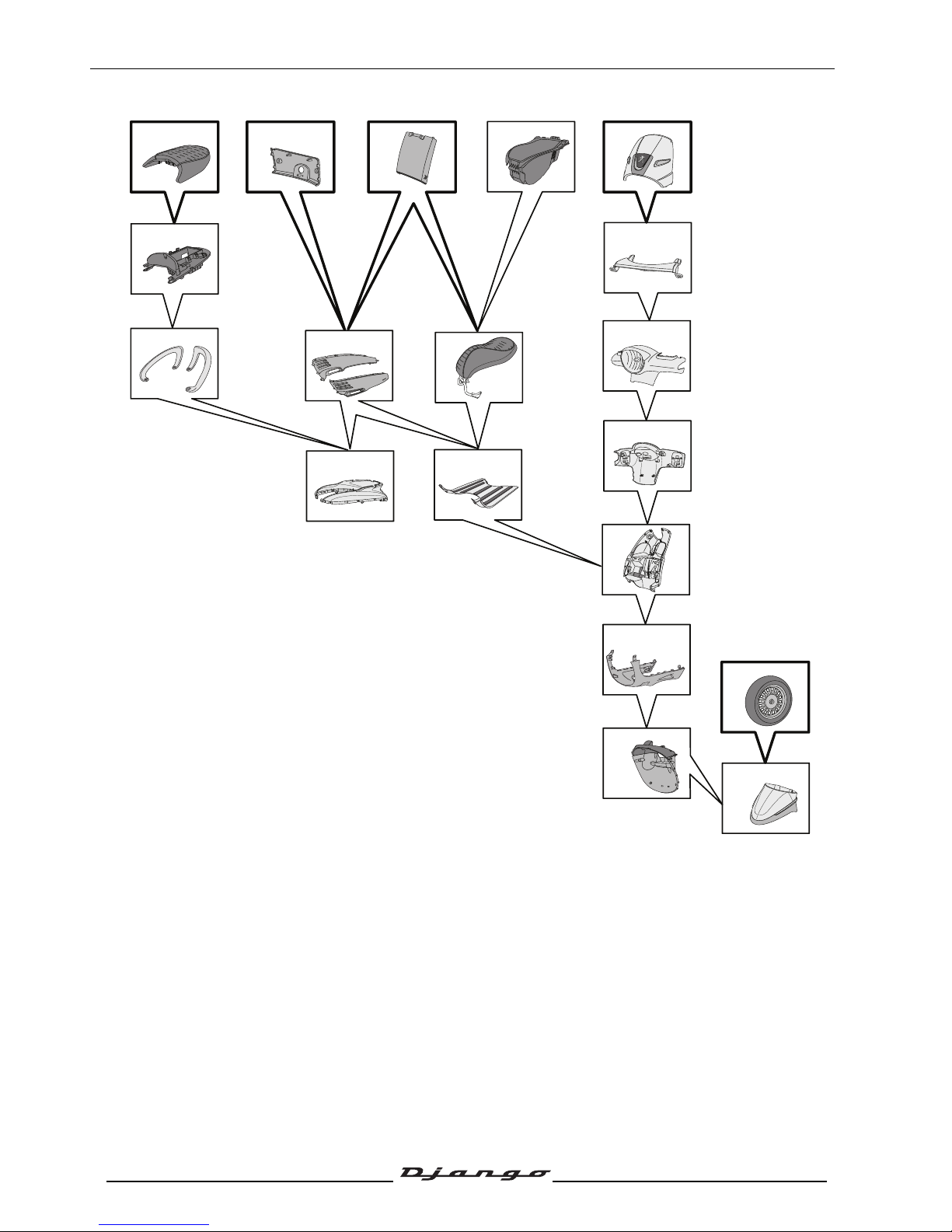
Body component sequence of disassembly
1. Front shield panel *
2. Front mudguard
3. Mudguard
4. Front wheel *
5. Bottom panel
6. Floor panel
7. Central panel *
8. Lower side fairing
9. Upper side fairing
10.Rear central fairing *
11.Grab handle
12.Battery holder
13.Passenger backseat *
14.Saddle storage compartment
15.Rider saddle
16.Rear shield
17.Handlebar rear fairing
18.Handlebar front fairing
19.Sheath guide
* This item may be removed on its own.
8
14
11
12
2
3
15
9
7*13* 10* 1*
18
17
19
16
6
4*
5
Page 21
BODY PANELS
20
Reproduction or translation, even partial, is forbidden without the written consent of Peugeot Scooters
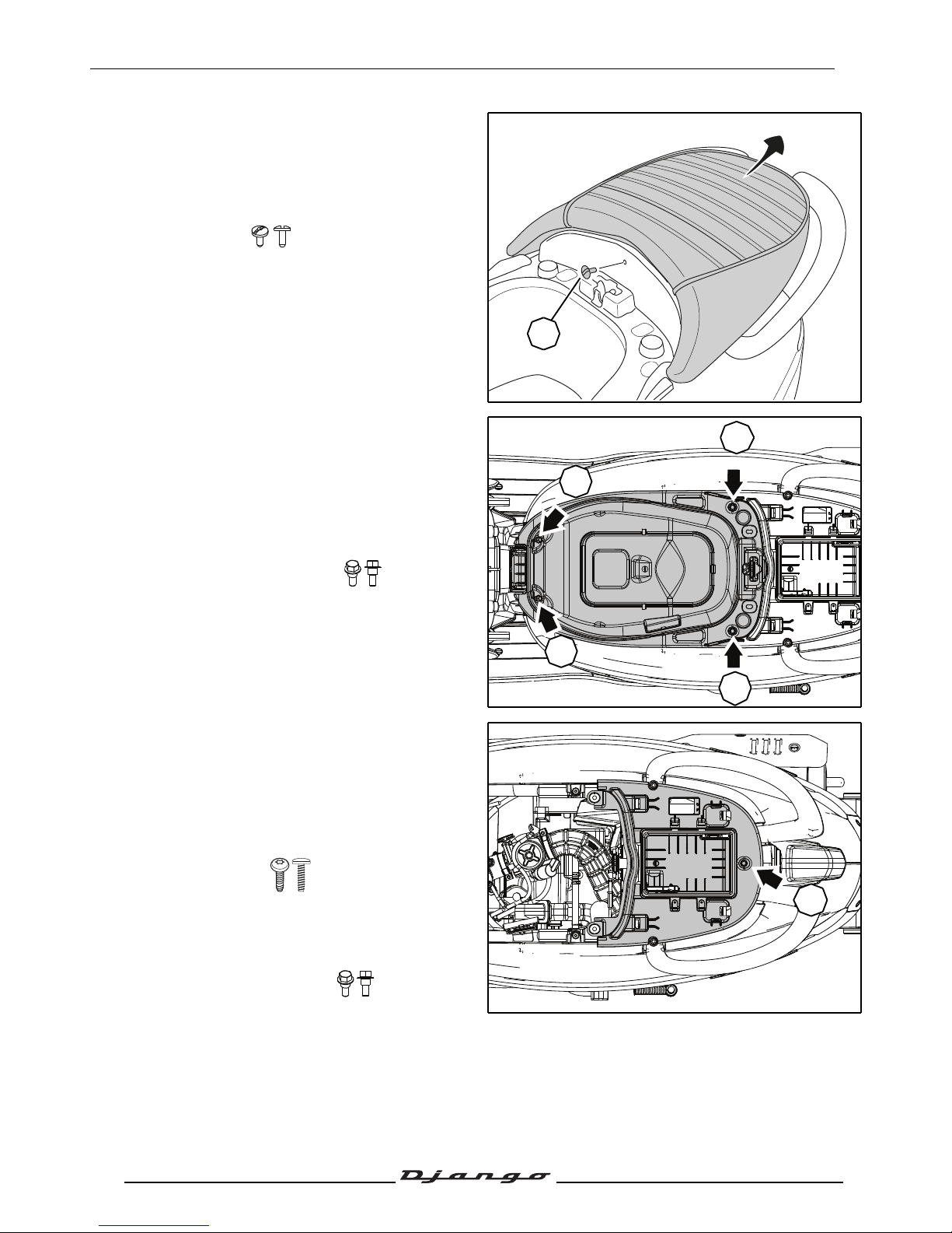
Removal of the passenger's saddle
Procedure 1.
- Open the saddle storage compartment.
- Remove the passenger seat.
• 1 (A) screws.
Removal of the storage compartment
Procedure 2.
- Remove the passenger seat. See: Procedure 1
page 20.
- Remove the storage compartment.
• 4 washer head screws (B).
Removal of the battery holder
Procedure 3.
- Remove the storage compartment. See:
Procedure 2 page 20.
- Remove the battery cover.
• 2 plastic screws.
- Disconnect and remove the battery.
- Remove the fuse holders.
- Remove the battery bracket.
• 1 washer head screw (C).
A
B
B
B
B
C
Page 22
BODY PANELS
21
Reproduction or translation, even partial, is forbidden without the written consent of Peugeot Scooters
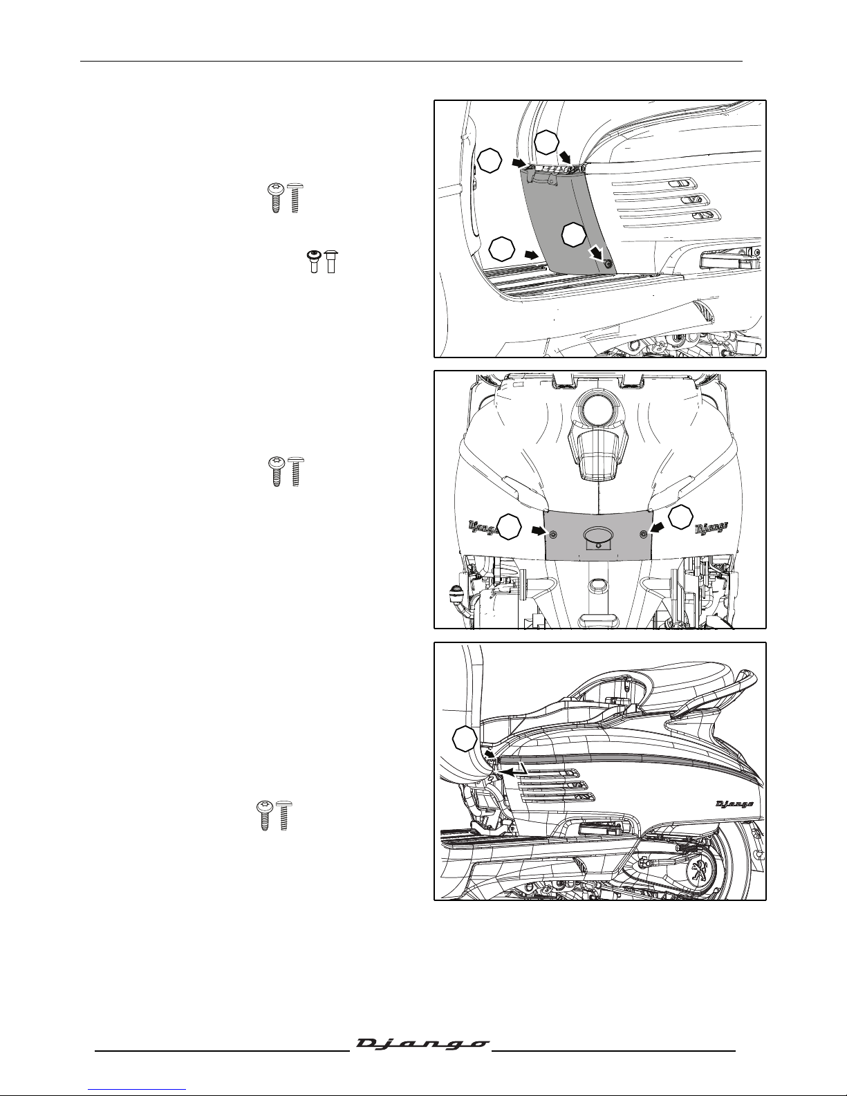
Remove the central fairing under the
saddle
Procedure 4.
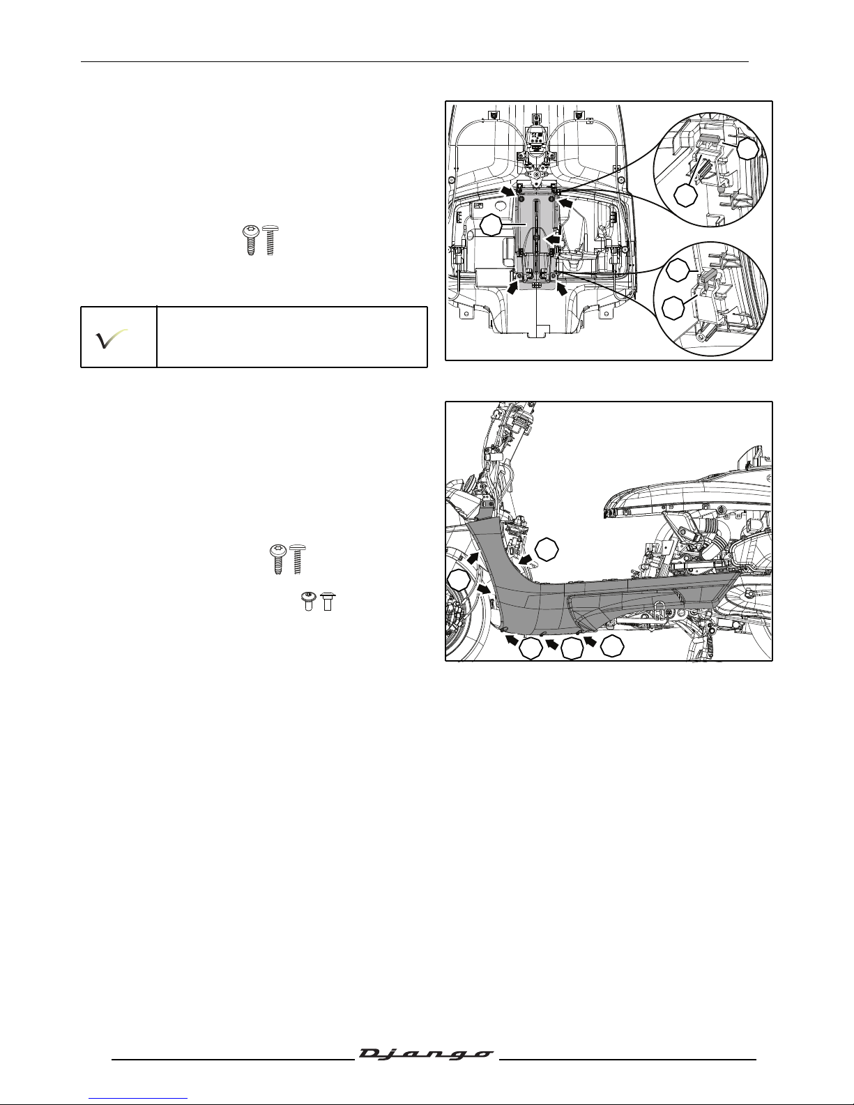
- Remove the central fairing under the saddle.
• 2 plastic screws (A).
• 2 washer head screws (B).
Removal of the central cover panel
Procedure 5.
- Remove the central cover panel.
• 2 plastic screws (C).
- Disconnect the license plate light.
Removal of a lower RH or LH side fairing
Procedure 6.
- Remove the central fairing under the saddle.
See: Procedure 4. page 21.
- Remove the central cover panel. See:
Procedure 5. page 21.
- Remove the chrome trim.
- 1 plastic screws (A).
- Push the front of the trim away slightly and then
slide it towards the front of the vehicle.
B
A
A
B
C
C
A
Page 23
BODY PANELS
22
Reproduction or translation, even partial, is forbidden without the written consent of Peugeot Scooters
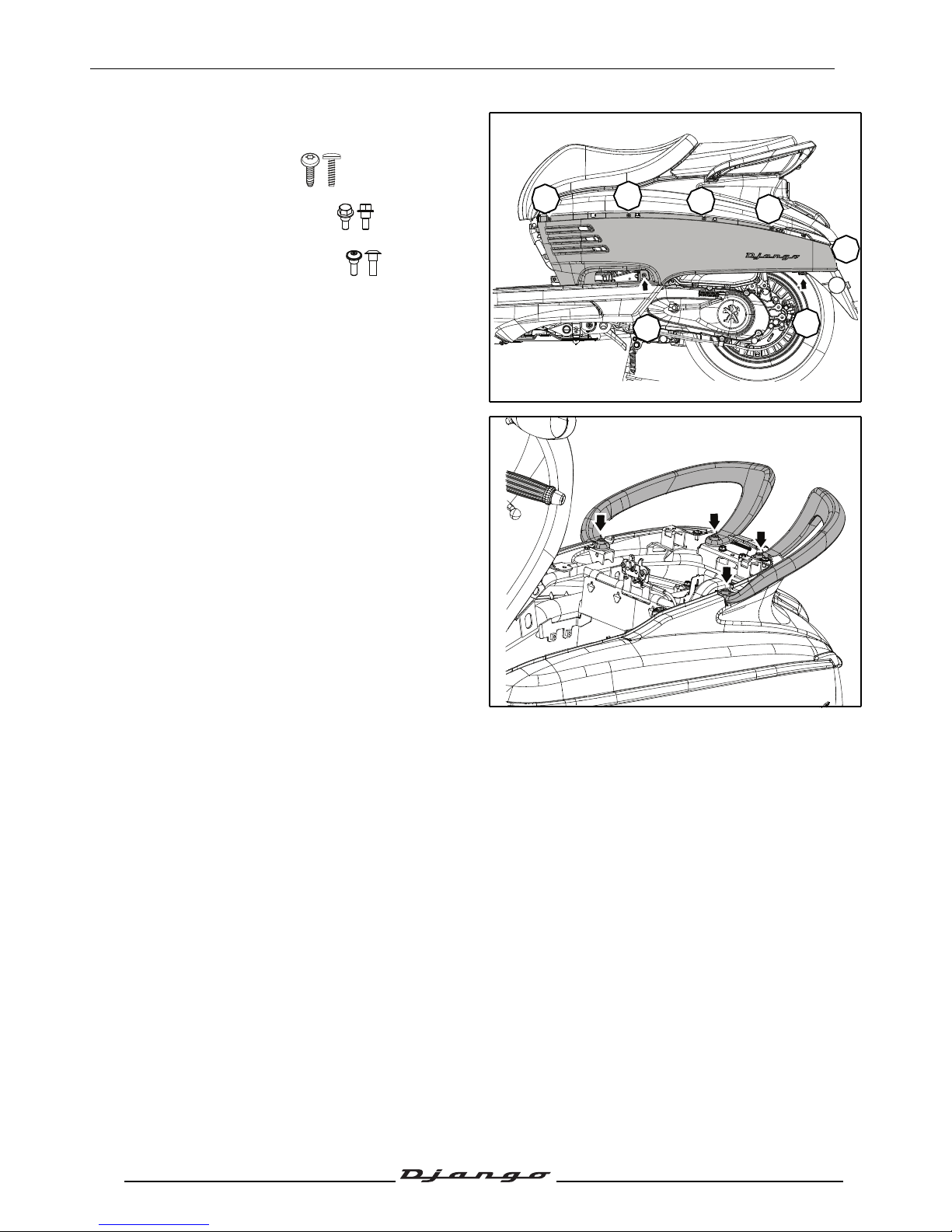
- Open the foot rest (1).
- Remove the lower side fairing.
• 4 plastic screws (B).
• 1 washer head screw (C).
• 2 washer head screws (D).
Removal of the grab handles
Procedure 7.
- Remove the battery bracket. See: Procedure 3.
page 20.
- Remove the grab handles.
• 4 Ø8 mm screw.
B
B
B
B
C
D
D
Page 24
BODY PANELS
23
Reproduction or translation, even partial, is forbidden without the written consent of Peugeot Scooters
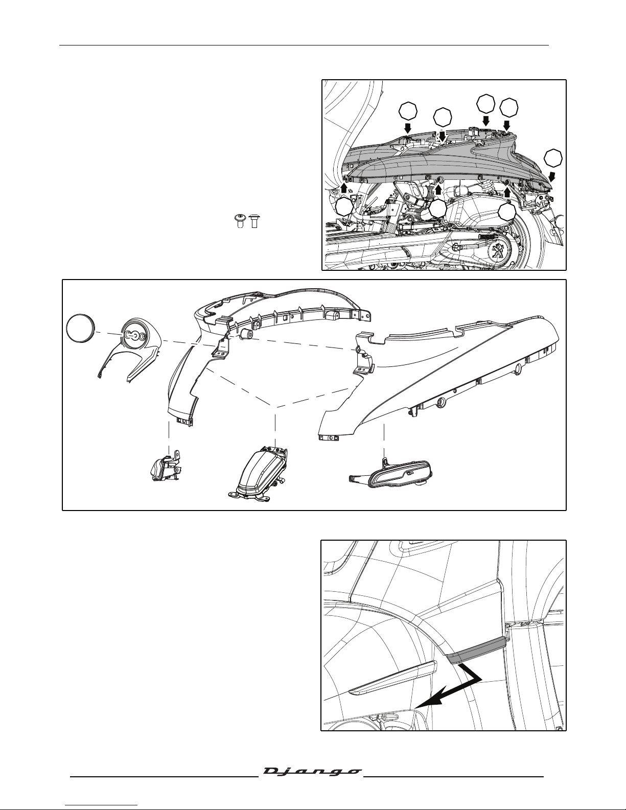
Removal of the upper side fairing
assembly
Procedure 8.
- Remove the lower side fairing. See:
Procedure 6. page 21.
- Remove the grab handles. See: Procedure 7.
page 22.
- Remove the upper side fairing assembly.
• 12 washer head screws (E).
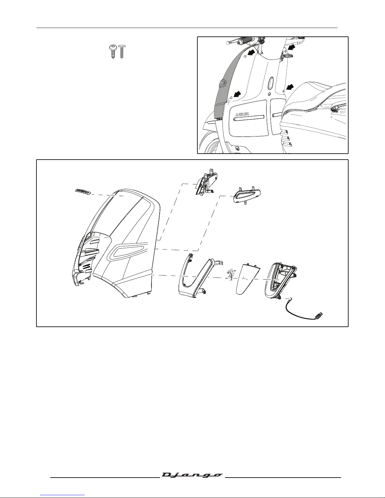
Removal of the front shield panel
Procedure 9.
- Unclip the front of the trim, then slide it towards
the front of the vehicle.
- Remove the 2 chrome trims.
E
E
E
E
E
E
E
E
Page 25
BODY PANELS
24
Reproduction or translation, even partial, is forbidden without the written consent of Peugeot Scooters
- Remove the front shield panel.
• 4 plastic screws.
- Disconnect:
• The indicators.
• The outside temperature probe.
• The side light (depending on the model).
Page 26
BODY PANELS
25
Reproduction or translation, even partial, is forbidden without the written consent of Peugeot Scooters
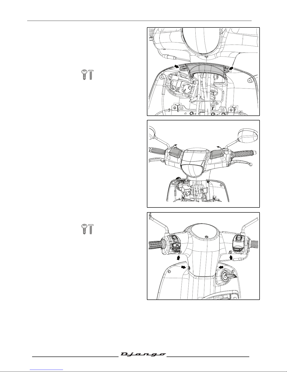
Removal of the head light fairing
Procedure 10.
- Remove the front shield panel. See:
Procedure 9. page 23.
- Remove the sheath guide.
• 2 plastic screws.
- Lever off the 2 master cylinder covers through
the rearview mirror holes.
- Carefully unclip the upper part and remove the
head light fairing.
• 4 plastic screws.
- Disconnect the lighting.
Page 27
BODY PANELS
26
Reproduction or translation, even partial, is forbidden without the written consent of Peugeot Scooters
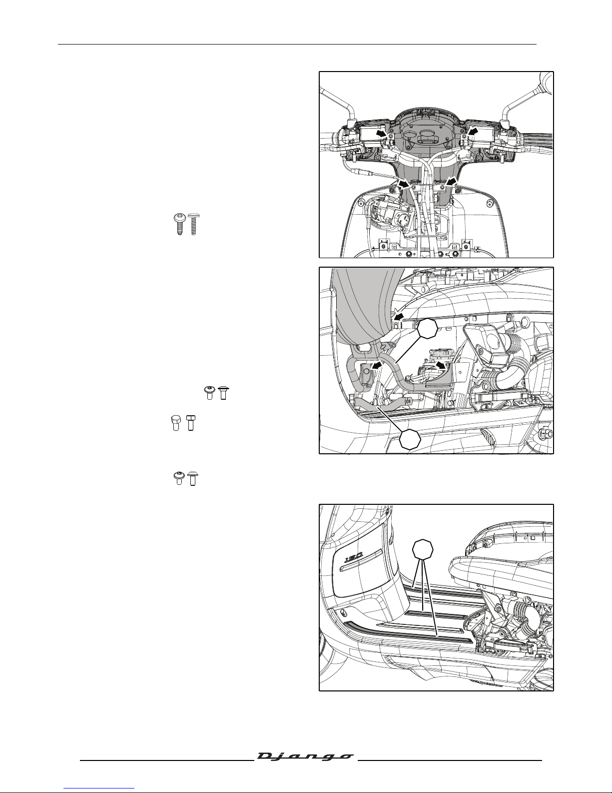
Removal of the speedometer fairing
Procedure 11.
- Remove the headlight fairing. See:
Procedure 10. page 25.
- Disconnect:
• The instrument panel.
• The control clusters.
• The brake light switches
- Remove the speedometer fairing.
• 4 plastic screws.
Removal of the footboard
Procedure 12.
- Remove the upper side fairings. See:
Procedure 6. page 21.
- Remove the storage compartment. See:
Procedure 2. page 20.
- Remove the bracket and the driver's saddle (1).
• 2 washer head screws.
• 2 Ø8 mm screw .
- Remove the central fairing bracket under the
saddle (2).
• 2 Ø5 mm screw
- Remove the 3 footboard mats (3).
2
1
3
Page 28
BODY PANELS
27
Reproduction or translation, even partial, is forbidden without the written consent of Peugeot Scooters
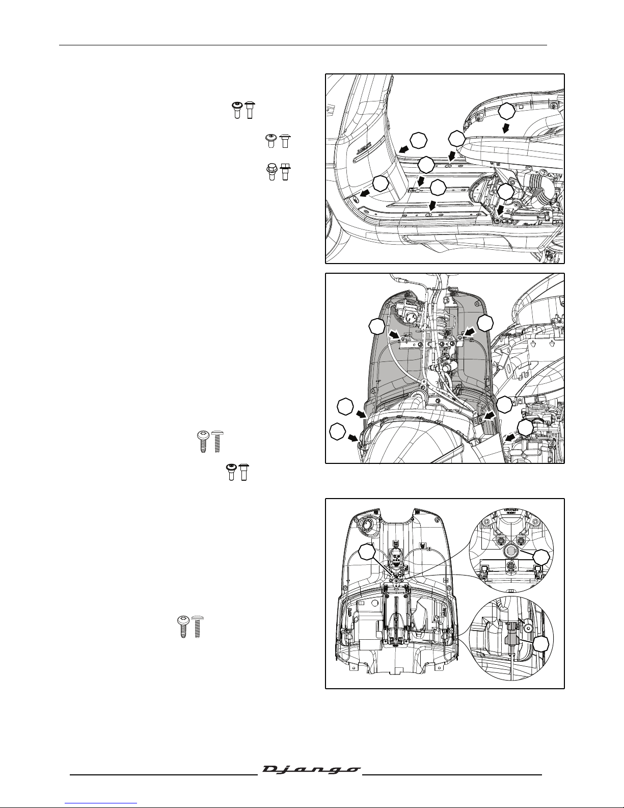
- Remove the footboard by sliding it towards the
rear of the vehicle and then lifting it.
• 2 washer head screws (A).
• 2 washer head screws Ø6 mm (B).
• 3 washer head screws Ø6 mm (C).
Removal of the rear shield panel
Procedure 13.
- Remove the front shield panel. See:
Procedure 9. page 23.
- Remove the footboard. See: Procedure 12.
page 26.
- Open the tank filler cap door.
- Remove the tank filler cap.
- Disconnect the accessory plug.
- Remove the rear shield panel.
• 4 plastic screws (A).
• 2 washer head screws (B).
Removal of the door-locking system
Procedure 14.
- Remove the rear shield panel. See:
Procedure 13. page 27.
- Remove the RH or LH door locking pin (1) and
its cable by turning it through a 1/4 turn.
- Remove the double-acting control plate (2).
• 3 plastic screws.
- Push back the locking ratchet (A) and extract
the barrel from the rear shield panel.
2
1
A
A
B
B
C
C
C
A
B
A
B
A
A
A
2
1
Page 29
BODY PANELS
28
Reproduction or translation, even partial, is forbidden without the written consent of Peugeot Scooters
Removal of a RH or LH door
Procedure 15.
- Remove the rear shield panel. See:
Procedure 13. page 27.
- Remove the rear shield panel plate (1).
• 5 plastic screws.
- Remove the RH or LH door.
• 2 pins (2).
When refitting the doors, position the pin
indexing in the orifices (A).
Removal of the RH or LH under body
panel
Procedure 16.
- Remove the rear shield panel. See:
Procedure 13. page 27.
- Remove the RH or LH under body panel.
• 5 plastic screws (A).
• 1 washer head screw (B).
A
A
2
2
1
B
A
AA
A
Page 30
BODY PANELS
29
Reproduction or translation, even partial, is forbidden without the written consent of Peugeot Scooters
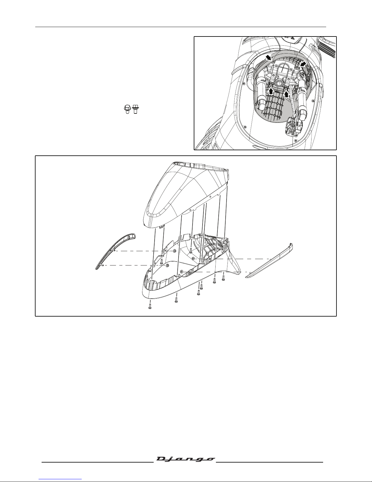
Removal of the front mudguard
Procedure 17.
- Suspend or immobilize the machine securely.
- Remove the front wheel.
Tightening torque :65 Nm.
- Remove the front mudguard.
• 4 washer head screws.
Page 31

BODY PANELS
30
Reproduction or translation, even partial, is forbidden without the written consent of Peugeot Scooters
Removal of the dirt shield
Procedure 18.
- Remove the RH and LH under body panel. See:
Procedure 16. page 28.
- Remove the front mudguard. See:
Procedure 17.page 29.
- Remove the lower mudguards.
• 4 plastic screws (A).
- Remove the upper mudguards.
A
A
A
A
Page 32
SERVICE OPERATIONS
31
Reproduction or translation, even partial, is forbidden without the written consent of Peugeot Scooters
SERVICE OPERATIONS
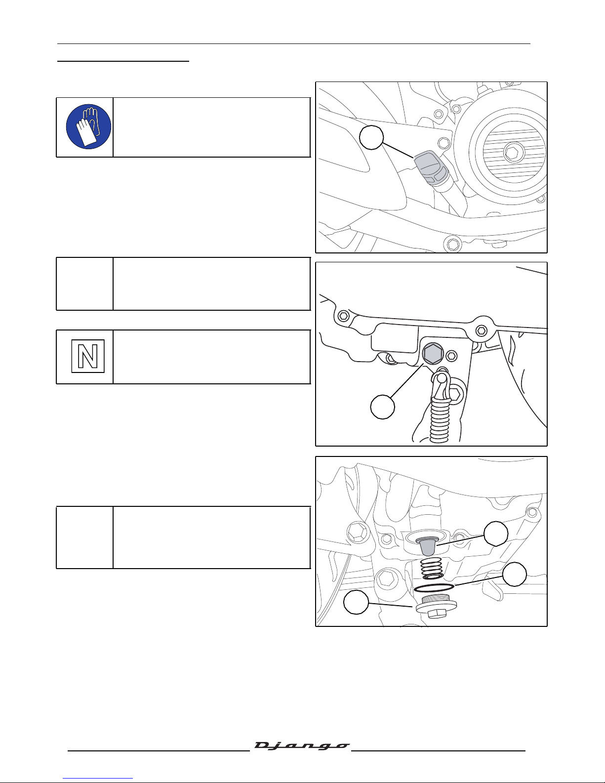
Empty the oil from the engine
The engine must be drained when it is
warm to allow the oil to run easier.
Wear gloves in order not to get burnt.
- Place the vehicle on its central stand on flat
ground.
- Remove the engine's oil filler cap (1).
Remove the drainage cap and its seal (2)
and allow the oil to drip into a recipient.
Tightening torque:40 Nm.
Replace the copper seal every time you
change oil.
- Remove the strainer cap (3) and clean the
strainer.
Tightening torque:15 Nm.
Every time oil is changed, the filter (4)
must be cleaned and the O-ring
changed (5).
1
2
4
5
3
Page 33
SERVICE OPERATIONS
32
Reproduction or translation, even partial, is forbidden without the written consent of Peugeot Scooters
- Put back the drainage cap and strainer cap, fitted
with a new seal.
Tightening torque: 40 Nm.
- Pour the required quantity of oil corresponding to
the manufacturer's standards into the filler hole:
• 0.95 L at oïl change.
- Fit the filler cap.
- Start the engine and let it run for a short while.
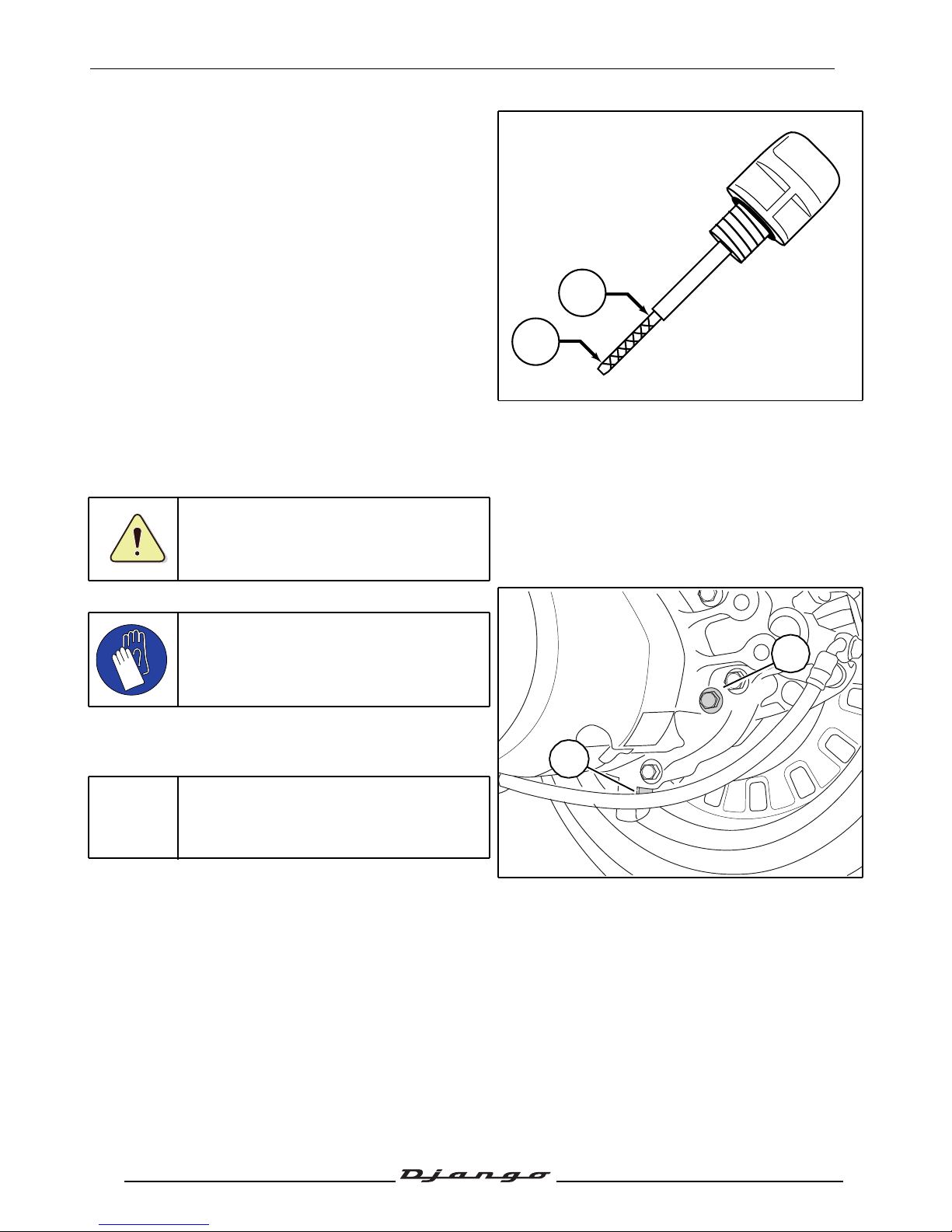
- Remove the engine's oil filler cap/gauge.
- Wipe dry the filler cap/gauge and fit it back but do
not screw it into the filler hole.
- Remove the filler cap/gauge and check the oil
level.
A. Oil level low.
B. Oil level high.
- Add oil if necessary.
Check the level with the machine parked
on its centre stand, on level ground.
Draining the relay box
The engine must be drained when it is
warm to allow the oil to run easier.
Wear gloves in order not to get burnt.
- Place the vehicle on its central stand on flat
ground.
- Remove the relay box filler cap (1)
Remove the drainage cap and its seal (2)
and allow the oil to drip into a recipient.
- Re-install the plug with a new seal.
- Pour the required quantity of oil corresponding to
the manufacturer's standards into the filler hole.
• 0.18 L at oïl change.
- Fit the filler cap.
Tightening torque: 10 Nm.
B
A
2
1
Page 34
SERVICE OPERATIONS
33
Reproduction or translation, even partial, is forbidden without the written consent of Peugeot Scooters
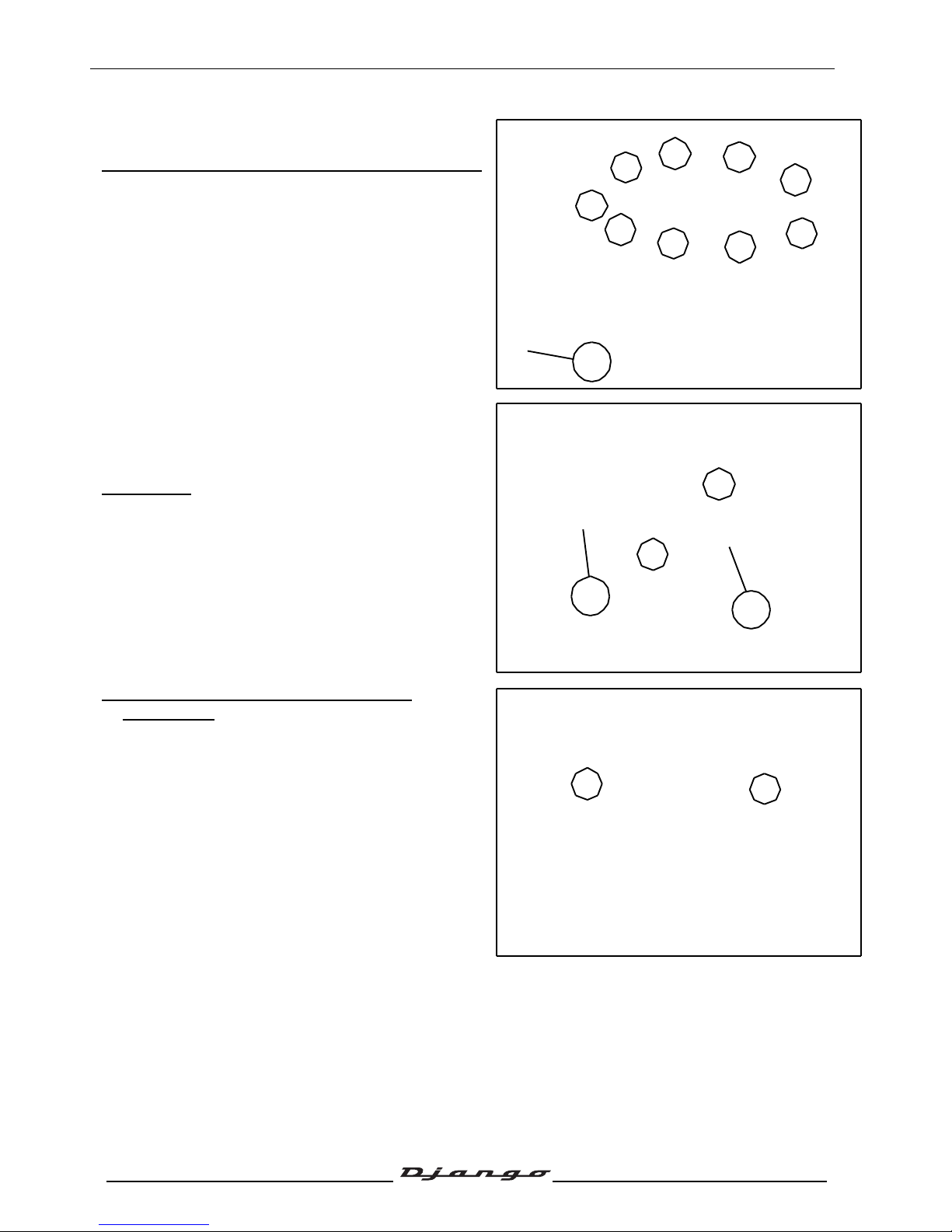
Replacing the air filter
Replacing the air filter with transmission maintenance
- Remove the lower LH side fairing. See:
Procedure 6. page 21.
- Remove the air filter cover (9 bolts) and its seal.
- Remove the inlet silencer drain plug to let
humidity and oil drip out (1).
- Remove the air filter (2).
- Clean inside the air filter box.
- Clean the oil vapour return filter (3).
Reassembly
- Fit a new air filter.
- Fit the gasket.
- Install the air filter cover.
Replacing the air filter without transmission
maintenance
- Remove the storage compartment. See:
Procedure 2. page 20.
- Remove the 2 screws that secure the air filter.
1
2
3
Page 35
SERVICE OPERATIONS
34
Reproduction or translation, even partial, is forbidden without the written consent of Peugeot Scooters
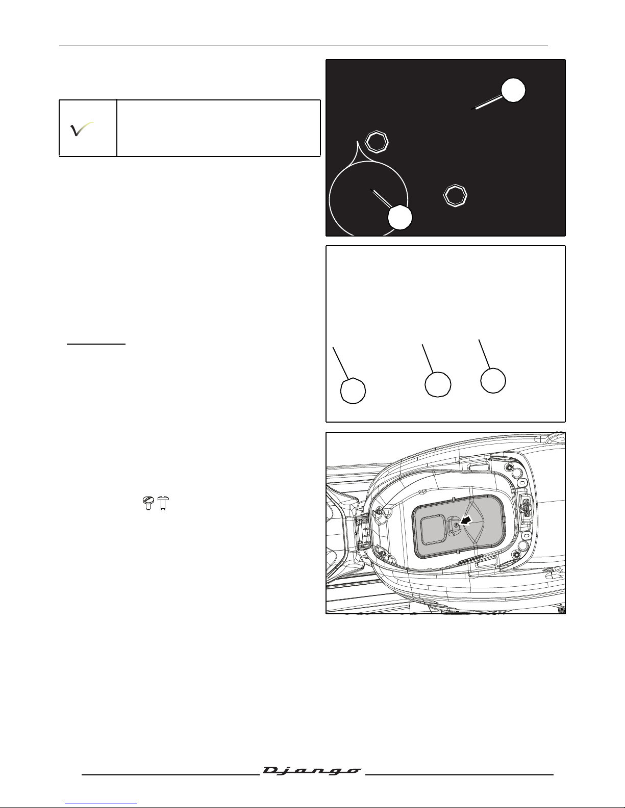
- Remove the air filter unit through the undersaddle storage compartment space. (1 collar and
1 screws)
Use a cloth to protect the cover of the air
unit.
Take care not to damage the throttle
control when bringing out the air unit.
- Disconnect the relay box air vent hose (1).
- Disconnect the oil vapour return pipe (2).
- Remove the air filter cover (9 bolts) and its seal.
- Remove the inlet silencer drain plug to let
humidity and oil drip out (3).
- Remove the air filter (4).
- Clean inside the air filter box.
- Clean the oil vapour return filter (5).
Reassembly
- Fit a new air filter.
- Fit the gasket.
- Install the air filter cover.
Removal of the spark plug
- The engine must be cold.
- Open the saddle.
- Remove the access door.
• 1 screw.
1
2
4
3
5
Page 36
SERVICE OPERATIONS
35
Reproduction or translation, even partial, is forbidden without the written consent of Peugeot Scooters
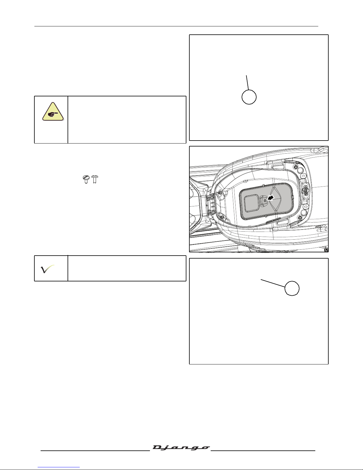
- Disconnect the suppressor (1).
- Remove the spark plug.
Tightening torque: 11 Nm.
- Recommended spark plug:
• NGK CR7 HSA.
• Electrode gap:0.7 to 0.8 mm.
Essential precautions: When re-installing,
srew in the spark plug (a few turns) by
hand.
Idle setting
- Open the saddle.
- Remove the access door.
• 1 screw.
Engine at operating temperature.
- Check the operating clearance in the throttle.
- Start the engine.
- Screw or unscrew the engine speed adjuster
screw (1) to alter the idle speed.
Idle setting: 1800
±100
rpm.
1
1
Page 37
SERVICE OPERATIONS
36
Reproduction or translation, even partial, is forbidden without the written consent of Peugeot Scooters
Removal of the primary transmission cover
- Remove the upper RH fairing. See: Procedure 6.
page 21
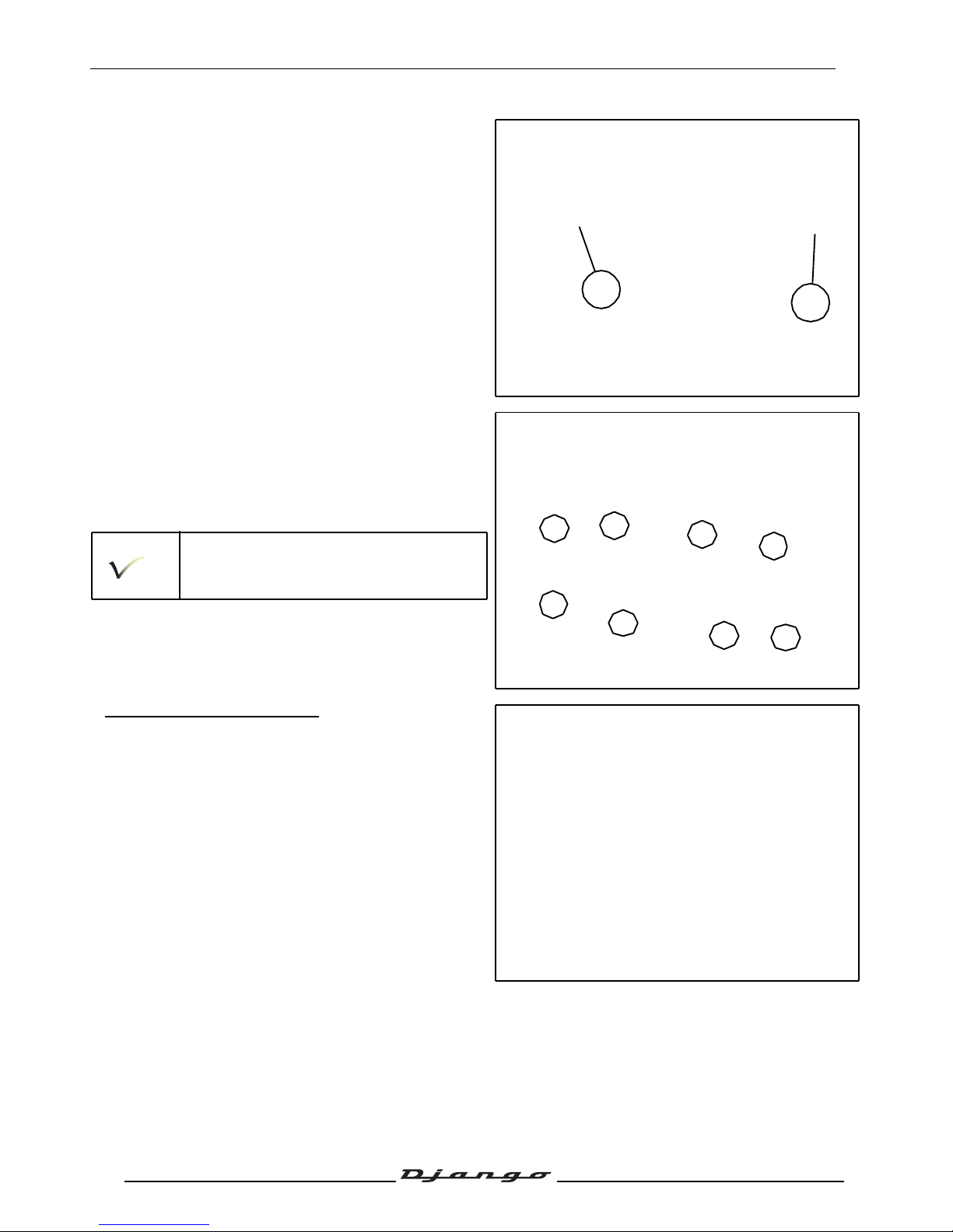
- Remove the 2 air filter box fixing bolts (A).
- Remove the transmission cover.
• 8 Ø6 mm screw.
Tightening torque: 10 Nm.
- Remove the paper gasket.
When re-installing, use a new gasket.
Removal of the starter system
- Remove the kickstart pedal.
• 1 Ø 8 mm screws.
A
A
Page 38
SERVICE OPERATIONS
37
Reproduction or translation, even partial, is forbidden without the written consent of Peugeot Scooters
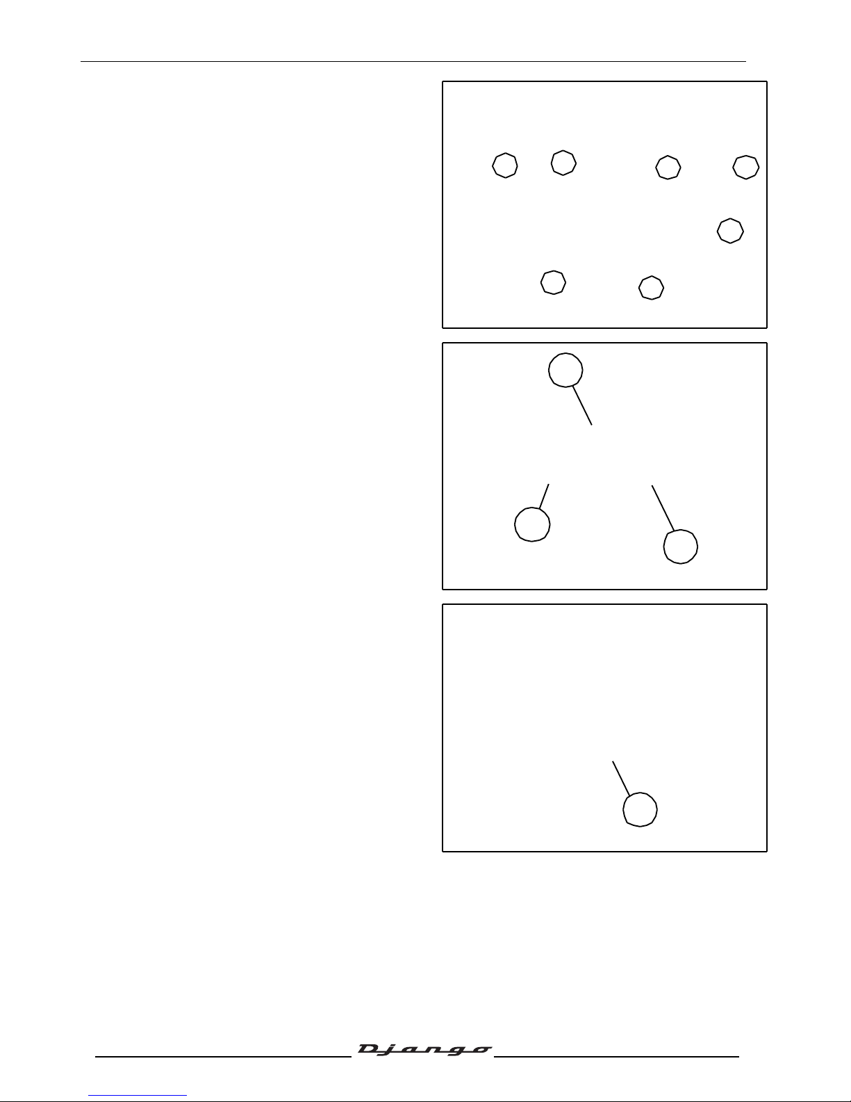
- Remove the plate.
• 7 Ø5 mm screws.
- Remove the paper gasket.
- Actuate the kick starter gear sector (1) by hand
and remove the kick starter drive piece (2) and
washer.
- Remove the lock ring (3), using circlip pliers.
- Remove the washer.
- Remove the elastic washer.
- Remove the starter gear sector (1) and the
washer (4) from the drive train cover.
4
2
1
3
Page 39
SERVICE OPERATIONS
38
Reproduction or translation, even partial, is forbidden without the written consent of Peugeot Scooters
Fitting the starter system
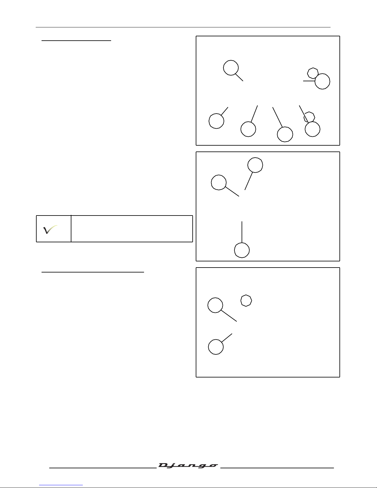
- Fit the washer (5) on the housing of the kick
starter drive piece.
- Fit the return spring (4), hook the longest buckle
on the cover's pin (A).
- Fit the starter gear sector (1) into the lubricated
bearing sleeve.
- Hook the second buckle (B) of the spring onto the
starter gear sector.
- Wind the spring so as to position the kick starter
sector on the stop (C) of the cover.
- Turn over the cover, fit the washer and the circlip
on the the gear sector spindle.
- Wind approximately 1/8th of a turn the gear
sector so as to place the kick starter drive
piece (2).
- Position the pin (6) on the kick starter drive piece
in the cover housing (D).
- Fit the paper gasket.
When re-installing, use a new gasket.
- Install the plate and the 7 screws.
Removal of the transmission air filter
- Remove the transmission air filter (1).
• 1 collar.
- Clean or change the filtering elment if
necessary (2).
1
C
A
4
B
5
2
D
6
1
2
Page 40
SERVICE OPERATIONS
39
Reproduction or translation, even partial, is forbidden without the written consent of Peugeot Scooters
Removal of the drive pulley
- Remove the upper RH fairing. See: Procedure 6.
page 21
- Removal of the primary transmission cover.
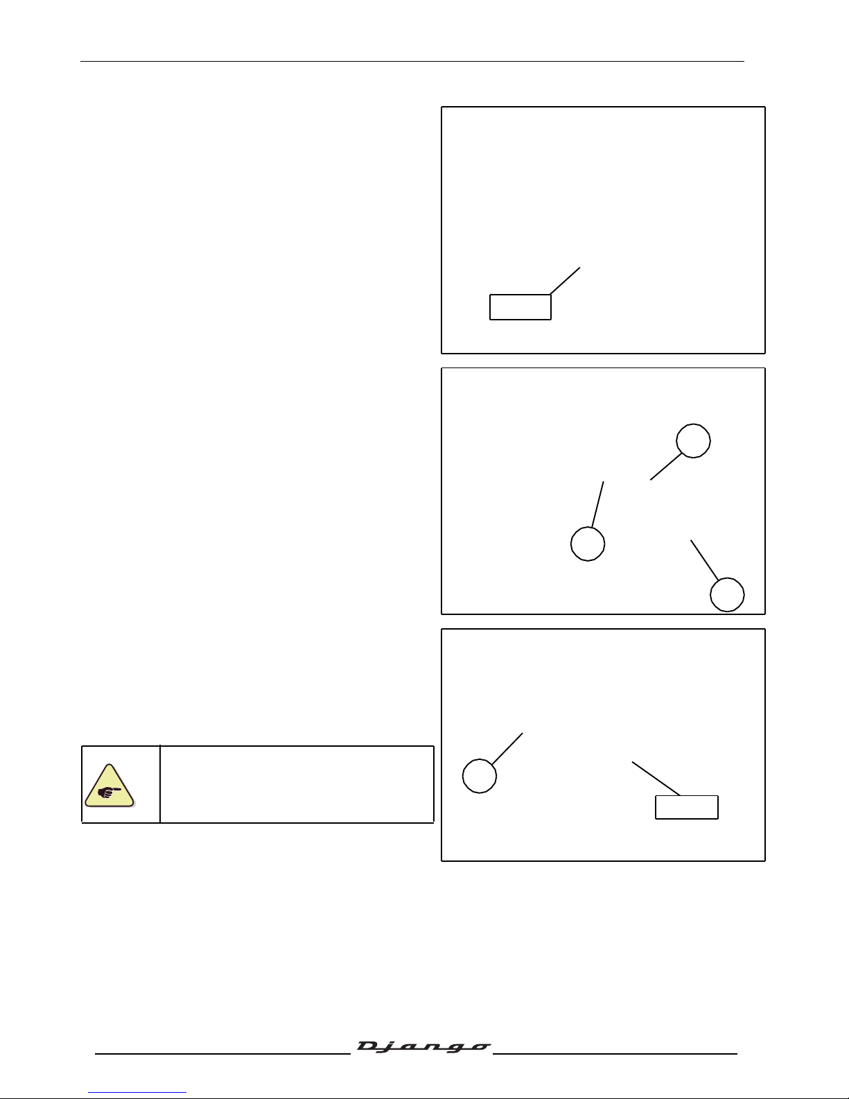
- Hold the fixed flange with tool P/N 752237.
- Remove the nut and the washer.
- Remove the fixed flange.
- Pull the belt aside (1).
- Remove the drive pulley (2) with the guide
hub (3).
Removal of the driven pulley
- Lock the clutch drum (1) with the pin wrench
P/N 752237.
- Remove the nut and the washer.
- Remove the clutch drum, the clutch drive pulley
and driven pulley assembly and belt.
Make a note of the direction of rotation of
the belt.
752237
3
2
1
1
752237
Page 41
SERVICE OPERATIONS
40
Reproduction or translation, even partial, is forbidden without the written consent of Peugeot Scooters
Changing the drive pulley bearings
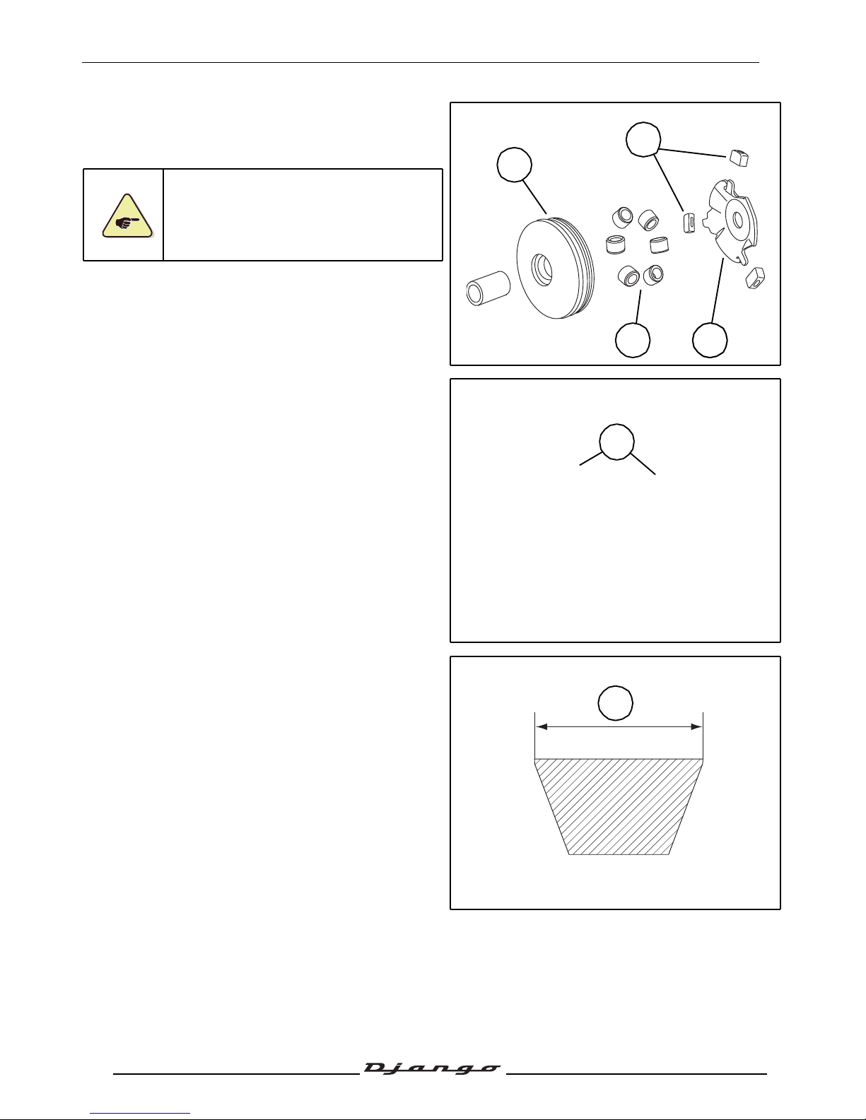
- Remove the ramp (1) and its 3 guides (2).
- Remove the moving flange (4) 6 bearings (3).
The bearings must be changed if they
show major signs of wear.
The guides shall be replaced if they show
signs of wear.
Make sure surface of the plates in contact with the belt
does not show any cracks or signs of abnormal
wear (A).
Checking the drive belt
- Measure the width of the belt (A).
Minimum width: 18.5 mm.
- Make sure the belt is not cracked.
4
3 21
1
A
A
Page 42
SERVICE OPERATIONS
41
Reproduction or translation, even partial, is forbidden without the written consent of Peugeot Scooters
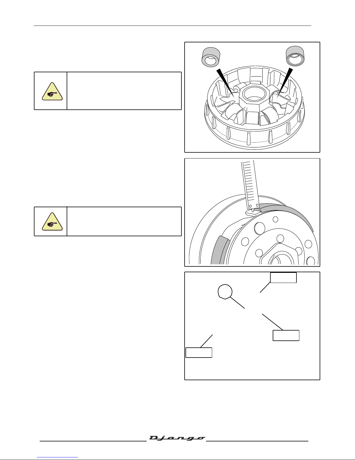
Reassembly:
- Proceed in reverse order to disassembly and do
not grease the bearings.
When refitting, respect the way the rollers
are installed.
- Grease the moving flange bore lightly (high
temperature grease).
Checking the thickness of the clutch
linings
- Using the depth calliper, measure the thickness
of the clutch linings.
Mini. thickness: 2 mm.
The balance of the clutch jaw assembly is
factory set, and therefore the assembly
cannot be dismantled.
Removal of the clutch lining assembly
- Compress the clutch and driven pulley assembly
using tool 758008 equipped with the protection
spacer P/N 801682.
- Remove nut (1) using spanner P/N 752361.
752361.
- Slacken tool P/N 758008.
752361
801682
758008
1
Page 43
SERVICE OPERATIONS
42
Reproduction or translation, even partial, is forbidden without the written consent of Peugeot Scooters
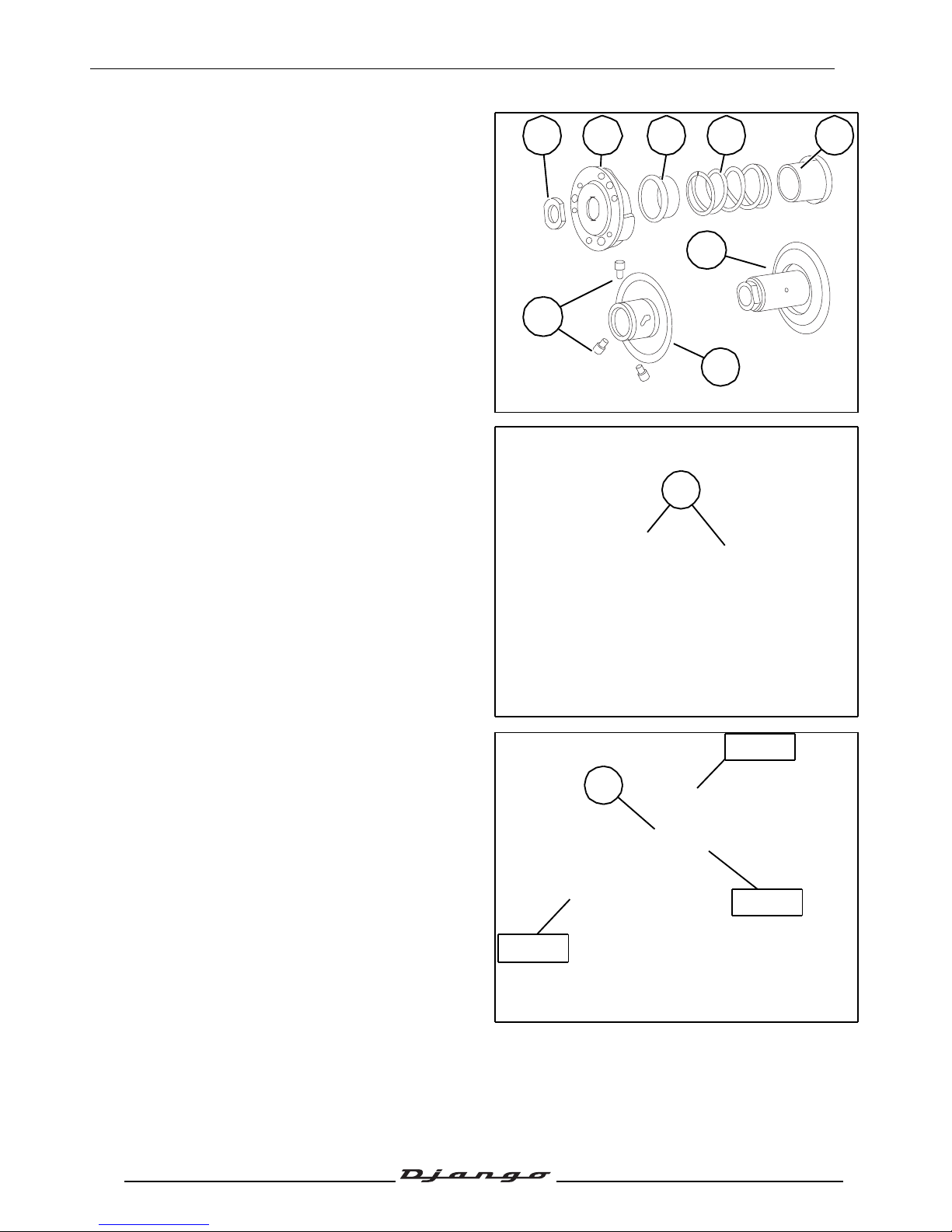
- Remove the clutch linings (2), the upper centring
sleeve (3), the spring (4), and the lower centring
sleeve (5).
- Remove the 3 pins (6) from the variable speed
drive seat.
- Separate the fixed (7) and rotating (8) flanges.
- Make sure surface of the plates in contact with
the belt does not show any cracks or signs of
abnormal wear.
Refitting the clutch lining assembly
- Make sure surface of the plates in contact with
the belt does not show any cracks or signs of
abnormal wear (A).
- Compress the clutch drive pulley and driven
pulley assembly with the tool P/N 758008.
- Tighten the nut (1).
Tightening torque: 58 Nm.
2 3
6
4 5
7
8
1
A
752361
801682
758008
1
Page 44
SERVICE OPERATIONS
43
Reproduction or translation, even partial, is forbidden without the written consent of Peugeot Scooters
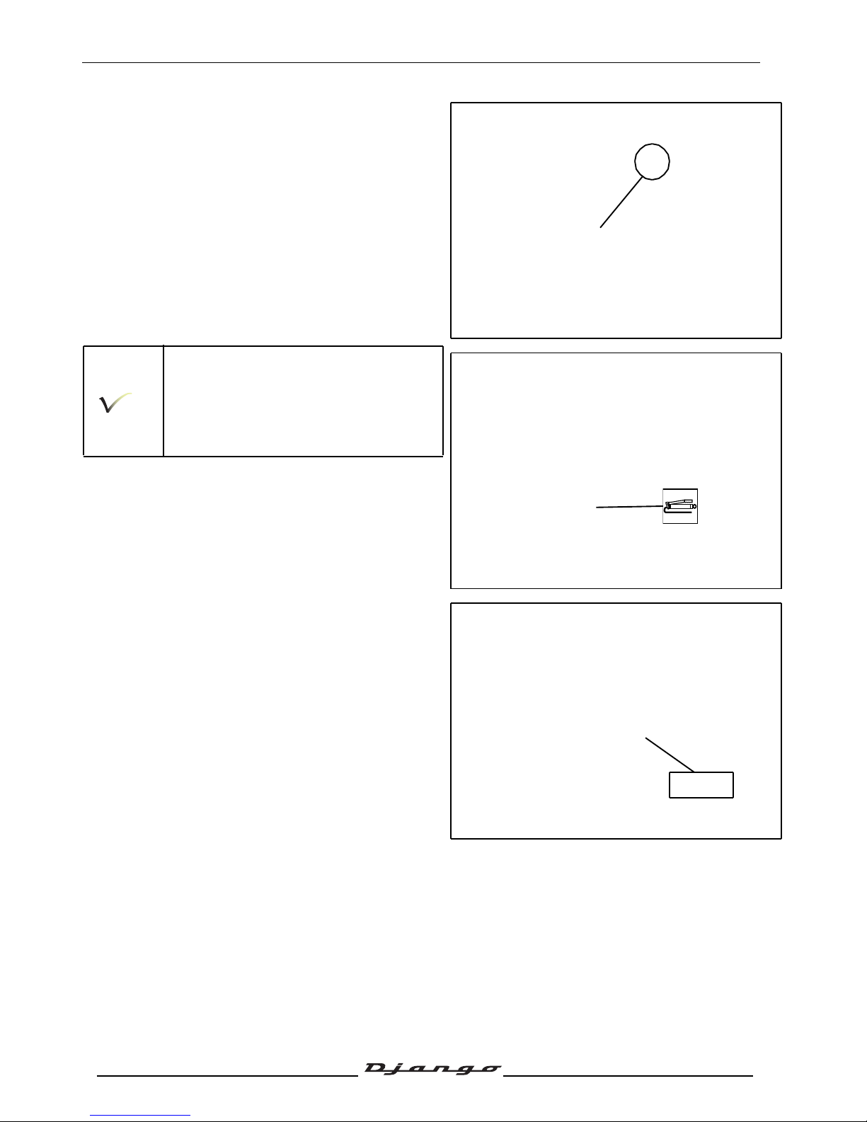
Installing the primary drive
- Fit the drive pulley with its guide hub (3) onto the
crank assembly.
Before fitting the clutch drive pulley and
driven pulley to the input shaft, fit the belt
into the pulley bottom by opening the
flanges by hand.
Respect the direction of rotation of the
belt which is shown by an arrow.
- Lightly grease the drawn cup needle roller
bearing of the driven pulley.
- Fit the clutch drive pulley and driven pulley
assembly.
- Fit the clutch cover.
- Fit washer.
- Lock the clutch drum (1) with the pin wrench
P/N 752237.
- Fit and tighten the nut.
Tightening torque: 58 Nm.
3
752237
Page 45
SERVICE OPERATIONS
44
Reproduction or translation, even partial, is forbidden without the written consent of Peugeot Scooters
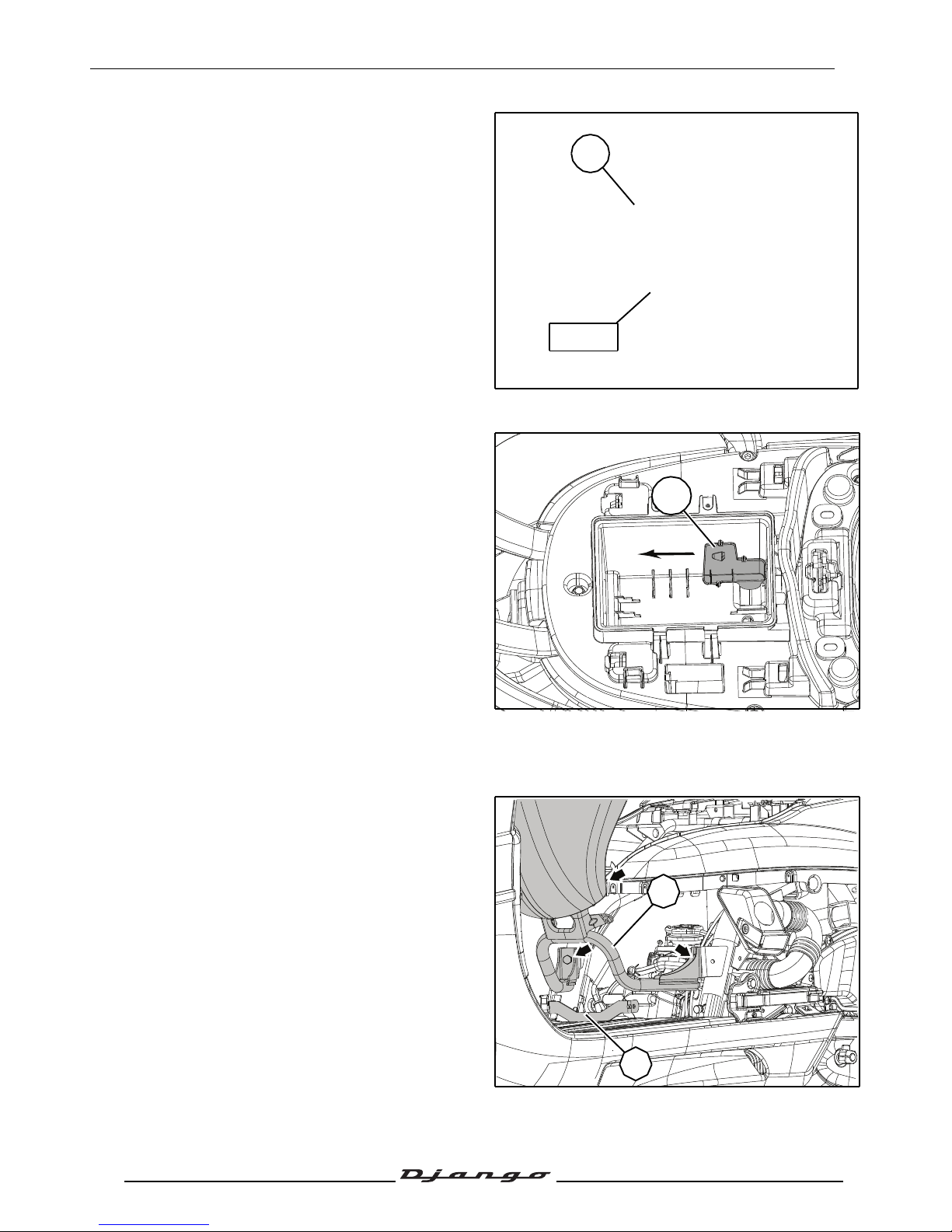
- Fit the fixed flange (3) to the crank assembly,
ensuring that it is properly positioned on the
crank assembly splines and checking that it is in
contact with the hub guide of the mobile flange.
- Fit the plain washer.
- Hold the fixed flange with tool P/N 752237.
- Fit and tighten the nut.
Tightening torque: 58 Nm.
Installing the valve clearance
- Remove the saddle storage compartment. See:
Range 2. page 20.
- Remove the central fairing under the saddle.
See: Procedure 4. page 21.
- Remove the passenger seat. See: Procedure 1.
page 20.
- Remove the battery cover.
- Disconnect and remove the battery.
- Suspend the rear of the machine.
- Remove the hatch giving access to the shock
absorber upper screw (1).
- Lift the rear of the machine.
- Remove the shock absorber upper fixing bolt.
Tightening torque: 47 Nm.
- Remove the bracket and the driver's saddle (1).
• 2 washer head screws Ø6 mm.
• 2 Ø8mm screw.
- Remove the central fairing bracket under the
saddle (2).
• 2 Ø6mm screw.
752237
3
1
2
1
Page 46
SERVICE OPERATIONS
45
Reproduction or translation, even partial, is forbidden without the written consent of Peugeot Scooters
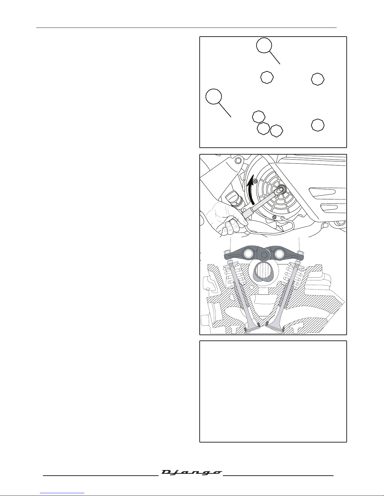
- Disconnect the oil vapour return pipe (2).
- Remove the pneumatic valve(3).
• 2 nutsØ6 mm
- Remove the rocker cover.
• 4 Ø6mm screw.
Tightening torque: 10 Nm.
- Rotate the engine by hand in the operating
direction in order to bring the rocker bearings on
the back of the cams.
- Using the set of feeler gauges, measure the
clearance of each valve.
Clearances:
• 0.12±0.02 mm at the intake.
• 0.12±0.02 mm at the exhaust.
3
2
Page 47
SERVICE OPERATIONS
46
Reproduction or translation, even partial, is forbidden without the written consent of Peugeot Scooters
Checking the valve clearance
- At the intake a 0.15 mm feeler gauge shouldn't
go.
- At the exhaust a 0.15 mm feeler gauge shouldn't
go.
- On the contrary, if the fealer gauge goes, reset
the clearances.
- Tighten the nock nut.
Tightening torque: 10 Nm.
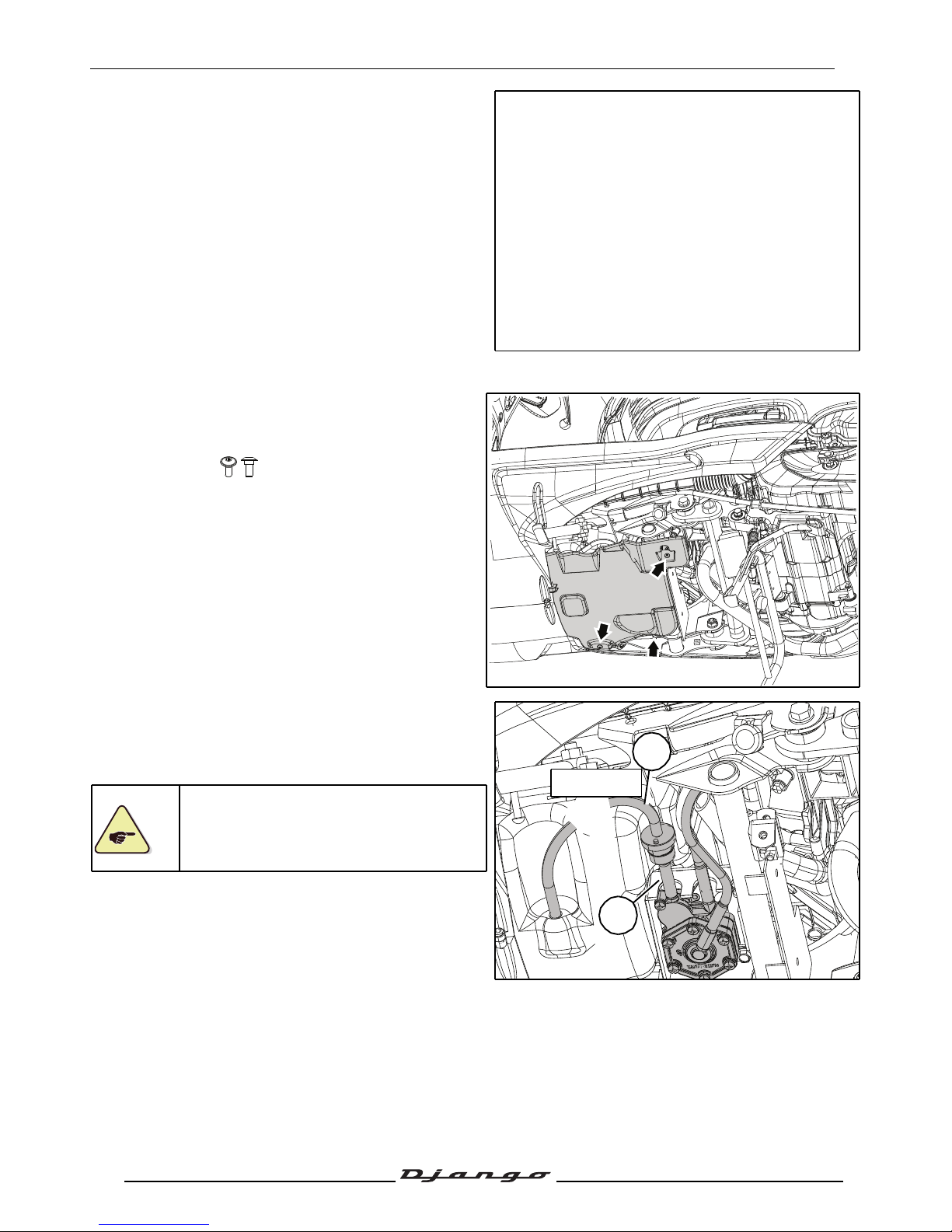
Changing the fuel filter
- Remove the protective shoe.
• 3 screw.
- Using tool part number 755996 clamp the fuel
supply hose between the tank and the fuel pump.
- Disconnect the 2 fuel pipes (1).
- Remove the fuel filter.
When re-installing, respect the direction
of installation of the filter shown by the
arrow which indicates in which direction
the fuel flows.
1
1
755996
Page 48
SERVICE OPERATIONS
47
Reproduction or translation, even partial, is forbidden without the written consent of Peugeot Scooters
Integral braking
Brake pad wear
Front brake
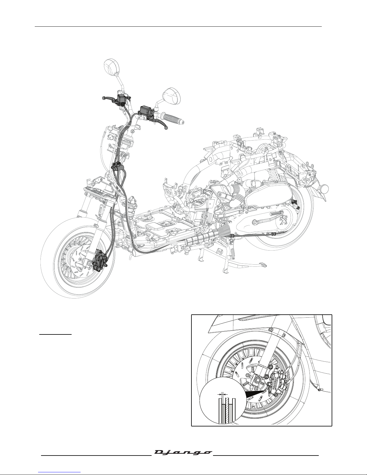
- If one of the 2 brake pads is worn down to the
minimum dimensions (A), the 2 brake pads must
be changed.
A. Mini. thickness: 1.5 mm.
- If it shows signs of wear, change the shaft.
A = 1.5mm
Page 49
SERVICE OPERATIONS
48
Reproduction or translation, even partial, is forbidden without the written consent of Peugeot Scooters
Rear brake
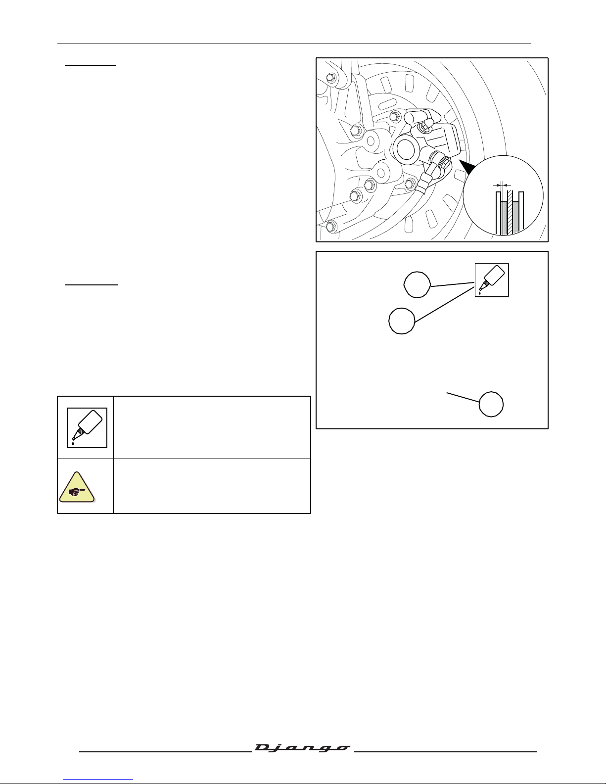
- If one of the 2 brake pads is worn down to the
minimum dimensions (A), the 2 brake pads must
be changed.
A. Mini. thickness: 1.5 mm.
Replacing the brake pads
Front brake
- Remove the brake pad pin cap (1).
- Loosen the brake pad pin first.
Tightening torque: 10 Nm.
- Remove the calliper (2 screw).
Tightening torque: 30 Nm.
When refitting the brake caliper, spread
standard thread lock on the bolts.
When changing the brake pads, it is
essential to replace the brake pad
attachment system (spindle, pin, clips, ...)
A = 1.5mm
1
GLUE
GLUE
Page 50
SERVICE OPERATIONS
49
Reproduction or translation, even partial, is forbidden without the written consent of Peugeot Scooters
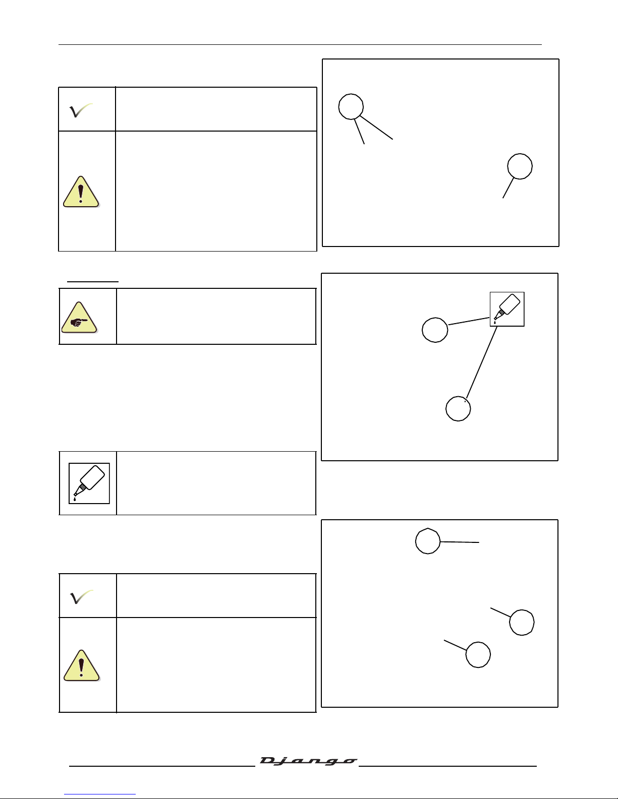
- Remove the brake pad pin (2).
- Remove the brake pads (3).
When refitting the brake pads, push the
pistons all the way into their housing.
After refitting, actuate the brake levers
several times to bring the brake pads
against the brake disc.
Rear brake
When changing the brake pads, it is
essential to replace the brake pad
attachment system (spindle, pin, clips, ...)
- Remove the wheel trim.
- Remove the 5screws fastening the rear wheel.
Tightening torque: 30 Nm.
- Remove the brake caliper (2 screw).
Tightening torque: 30 Nm.
When refitting the brake caliper, spread
standard thread lock on the bolts.
- Squeeze the caliper holder in order to remove the
first brake pad(1).
- Remove the second brake pad(2).
- Remove the brake pad spring (3).
When refitting the brake pads, push the
pistons all the way into their housing.
After refitting, actuate the brake levers
several times to bring the brake pads
against the brake disc.
2
3
GLUE
GLUE
1
2
3
Page 51
SERVICE OPERATIONS
50
Reproduction or translation, even partial, is forbidden without the written consent of Peugeot Scooters
Bleeding the integral circuit
Draining the main brake circuit
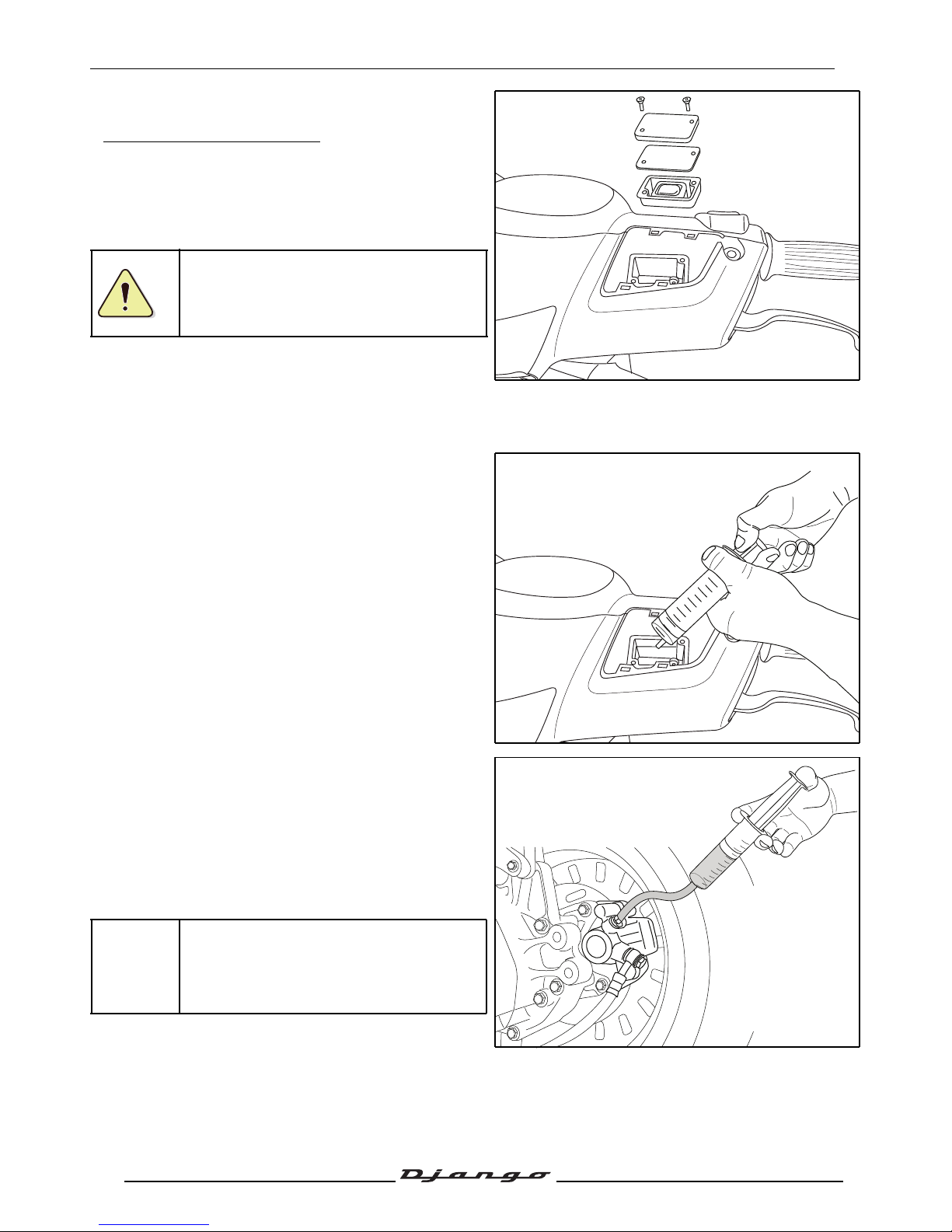
- Remove the master-cylinder cover. See:
Procedure10. page 25.
- Remove the front shield panel. See:
Procedure9.page 23.
Protect plastic parts that can be splashed
by brake fluid.
- Position the handlebars so that the master
cylinder will be horizontal.
- Remove the cover and the diaphragm from the
master cylinder.
• 2 screw.
- Using the syringe, empty the LH master cylinder.
- Fill the syringe with brake fluid.
- Connect the syringe to the bleed screw of the rear
calliper.
- Open the bleed screw by 1 to 2 turns.
- Inject the brake fluid slowly into the circuit until
the level inside the reservoir of the master
cylinder is halfway up.
- Close the bleeder screw.
Add brake fluid until it reaches the
maximum level.
Page 52
SERVICE OPERATIONS
51
Reproduction or translation, even partial, is forbidden without the written consent of Peugeot Scooters
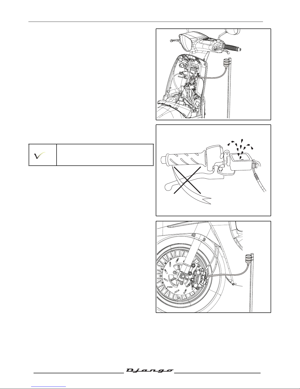
- Connect the reservoir containing brake fluid to
the modulator bleed screw using a transparent
pipe. The reservoir must be kept higher than the
modulator to easily check that the air bubbles are
being expelled.
- Open the bleed screw by 1 to 2 turns.
- Actuate the LH brake lever in an even way and
without undue haste while topping up with brake
fluid in the master cylinder.
Don't lean over the master cylinder when
bleeding the circuit in order not to get
splashed by brake fluid
- Stop the operation when no more bubbles are
expelled from the modulator bleeder screw.
- Close the bleeder screw.
- Connect the reservoir containing brake fluid to
the front brake calliper bleed screw using a
transparent pipe. The reservoir must be kept
higher than the brake calliper to easily check that
the air bubbles are being expelled.
- Open the bleed screw by 1 to 2 turns.
Page 53
SERVICE OPERATIONS
52
Reproduction or translation, even partial, is forbidden without the written consent of Peugeot Scooters
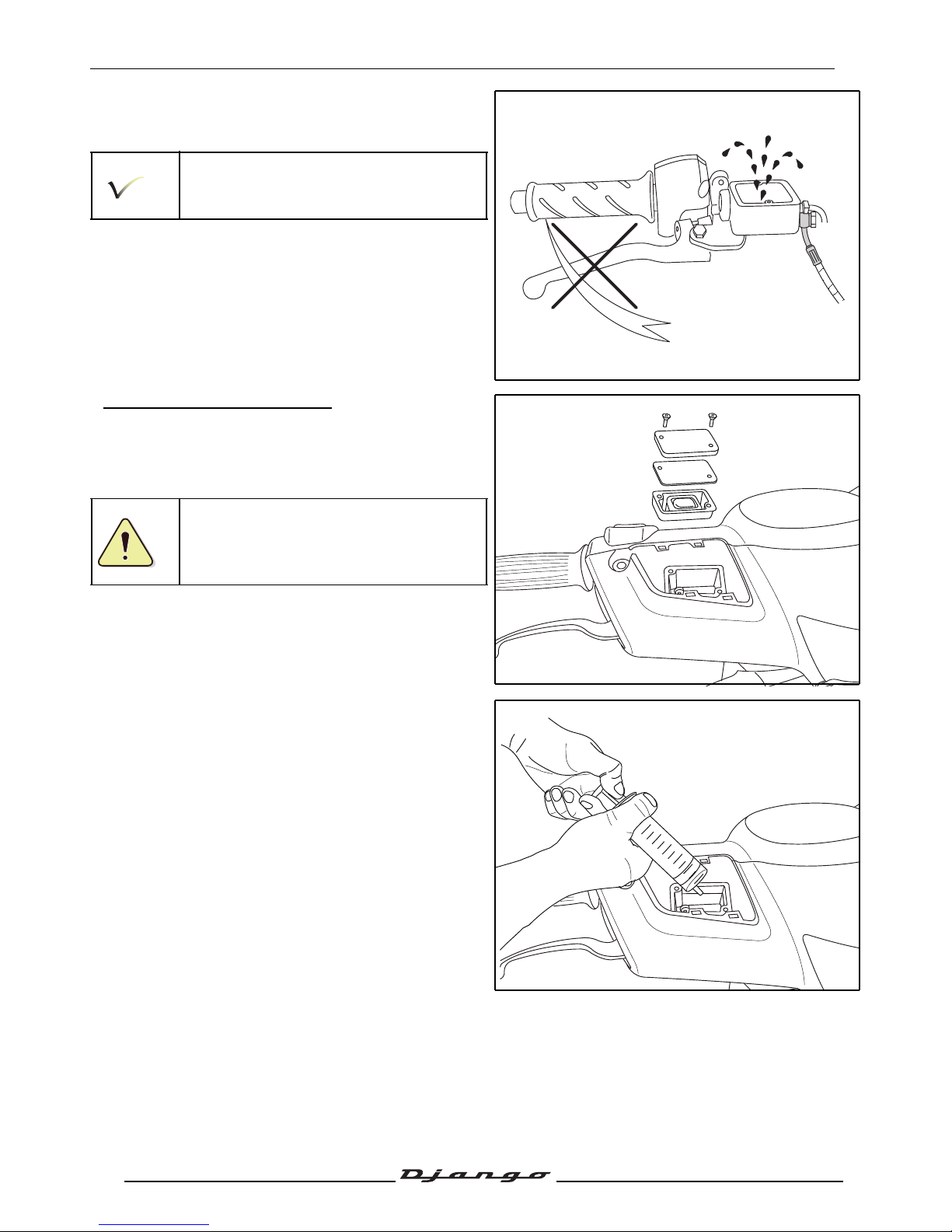
- Actuate the LH brake lever in an even way and
without undue haste while topping up with brake
fluid in the master cylinder.
Don't lean over the master cylinder when
bleeding the circuit in order not to get
splashed by brake fluid
- Stop the operation when no more bubbles are
expelled from the calliper bleeder screw.
- Close the bleeder screw.
Bleeding the emergency system
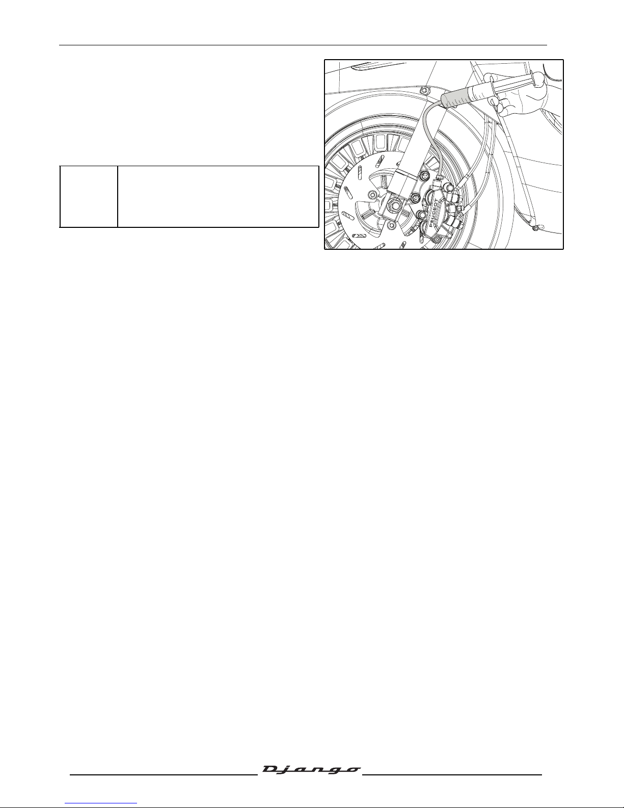
- Remove the master-cylinder cover. See:
Procedure10. page 25.
Protect plastic parts that can be splashed
by brake fluid.
- Remove the cover and the diaphragm from the
master cylinder.
• 2 screw.
- Using the syringe, empty the LH master cylinder.
- Position the handlebars so that the master
cylinder will be horizontal.
Page 54
SERVICE OPERATIONS
53
Reproduction or translation, even partial, is forbidden without the written consent of Peugeot Scooters
- Fill the syringe with brake fluid.
- Connect the syringe to the bleed screw of the rear
calliper.
- Open the bleed screw by 1 to 2 turns.
- Inject the brake fluid slowly into the circuit until
the level inside the reservoir of the master
cylinder is halfway up.
- Close the bleeder screw.
Add brake fluid until it reaches the
maximum level.
Page 55
SERVICE OPERATIONS
54
Reproduction or translation, even partial, is forbidden without the written consent of Peugeot Scooters
Conventional braking
Brake pad wear
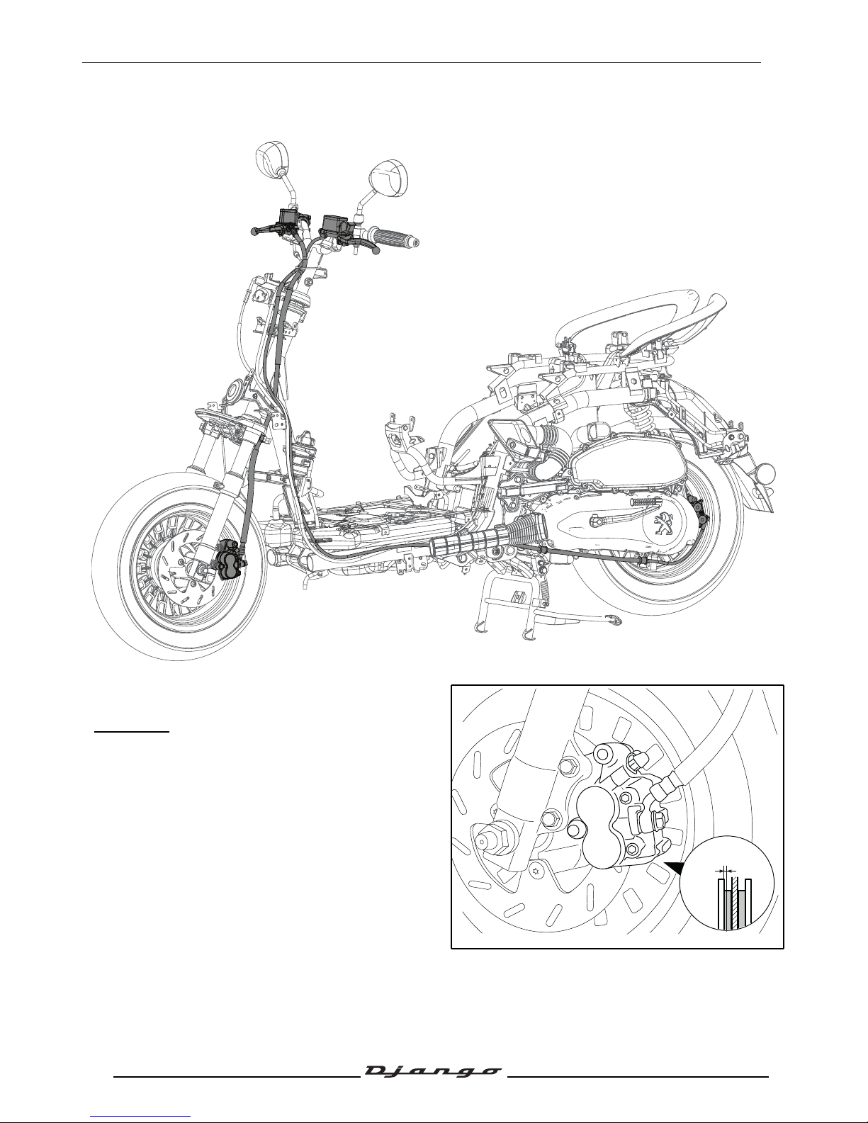
Front brake
- If one of the2 brake pads is worn down to the
minimum dimensions(A), the 2 brake pads must
be changed.
A. Mini. thickness: 1.5 mm.
- If it shows signs of wear, change the shaft.
A = 1.5mm
Page 56
SERVICE OPERATIONS
55
Reproduction or translation, even partial, is forbidden without the written consent of Peugeot Scooters
Rear brake
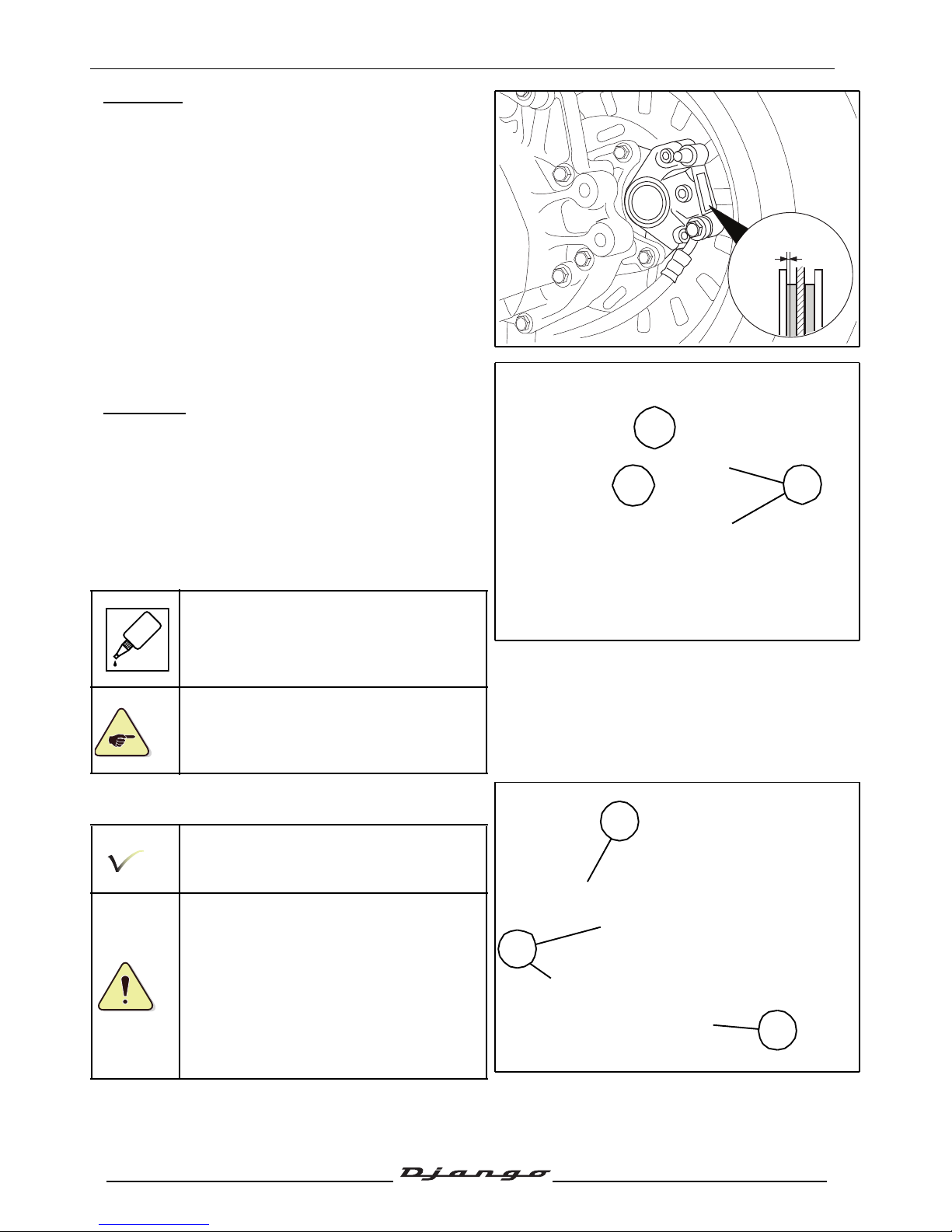
- If one of the2 brake pads is worn down to the
minimum dimensions(A), the 2 brake pads must
be changed.
A. Mini. thickness: 1.5 mm.
Replacing the brake pads
Front brake
- Remove the caps (1) on the brake pad pins.
- Loosen the brake pad pins beforehand.
Tightening torque: 10 Nm.
- Remove the calliper (2 screw).
Tightening torque: 30 Nm.
When refitting the brake caliper, spread
standard thread lock on the bolts.
When changing the brake pads, it is
essential to replace the brake pad
attachment system (spindle, pin, clips, ...)
- Remove the 2 spindles from the brake pads (2).
- Remove the brake pads(3).
When refitting the brake pads, push the
pistons all the way into their housing.
After refitting, actuate the brake levers
several times to bring the brake pads
against the brake disc.
A = 1.5mm
1
GLUE
2
2
3
Page 57
SERVICE OPERATIONS
56
Reproduction or translation, even partial, is forbidden without the written consent of Peugeot Scooters
Rear brake
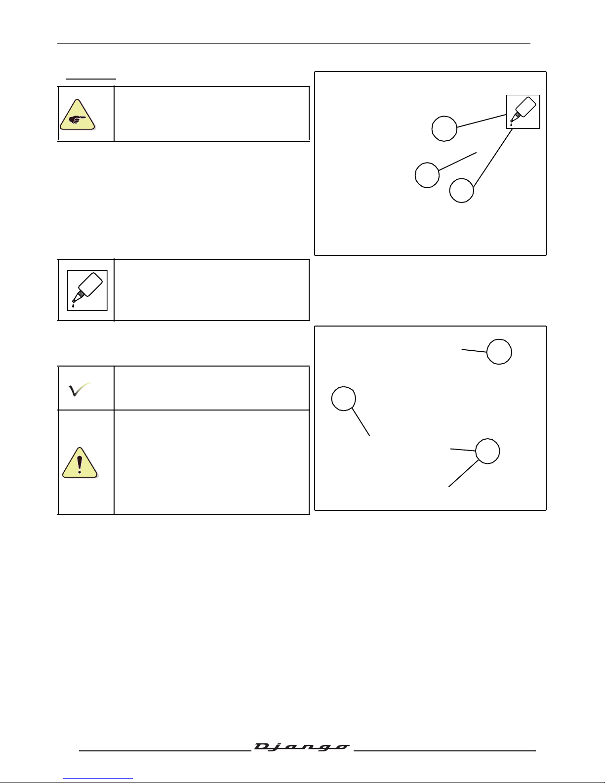
When changing the brake pads, it is
essential to replace the brake pad
attachment system (spindle, pin, clips, ...)
- Remove the wheel trim.
- Remove the 5screws fastening the rear wheel.
Tightening torque: 30 Nm.
- Loosen the brake pad pin first. (1)
- Remove the brake caliper (2 screw).
Tightening torque: 30 Nm.
When refitting the brake caliper, spread
standard thread lock on the bolts.
- Remove the brake pad pin (2).
- Remove the tension spring (3).
- Remove the brake pads(4).
When refitting the brake pads, push the
pistons all the way into their housing.
After refitting, actuate the brake levers
several times to bring the brake pads
against the brake disc.
GLUE
1
GLUE
2
3
4
Page 58
SERVICE OPERATIONS
57
Reproduction or translation, even partial, is forbidden without the written consent of Peugeot Scooters
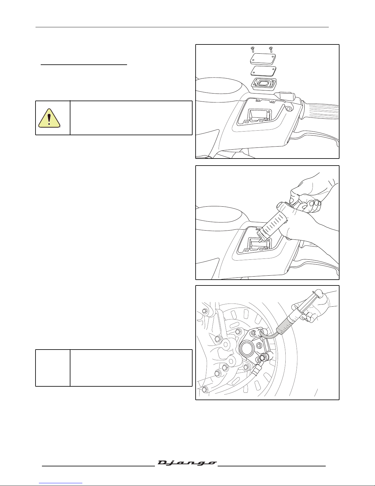
Drain the braking circuit
Draining the rear brake circuit:
- Remove the master-cylinder cover. See:
Procedure 10. page 25.
Protect plastic parts that can be splashed
by brake fluid.
- Remove the cover and the diaphragm from the
master cylinder.
• 2 screw.
- Using the syringe, empty the LH master cylinder.
- Position the handlebars so that the master
cylinder will be horizontal.
- Fill the syringe with brake fluid.
- Connect the syringe to the bleed screw of the rear
calliper.
- Open the bleed screw by 1 to 2 turns.
- Inject the brake fluid slowly into the circuit until the
level inside the reservoir of the master cylinder is
halfway up.
- Close the bleeder screw.
Add brake fluid until it reaches the
maximum level.
Page 59

SERVICE OPERATIONS
58
Reproduction or translation, even partial, is forbidden without the written consent of Peugeot Scooters
Draining the front brake circuit:
- Remove the master-cylinder cover. See:
Procedure 10.page 25.
Protect plastic parts that can be splashed
by brake fluid.
- Remove the cover and the diaphragm from the
master cylinder.
• 2 screw.
- Using the syringe, empty the LH master cylinder.
- Position the handlebars so that the master
cylinder will be horizontal.
- Fill the syringe with brake fluid.
- Connect the syringe to the bleed screw of the rear
calliper.
- Open the bleed screw by 1 to 2 turns.
- Inject the brake fluid slowly into the circuit until the
level inside the reservoir of the master cylinder is
halfway up.
- Close the bleeder screw.
Add brake fluid until it reaches the
maximum level.
Page 60
SERVICE OPERATIONS
59
Reproduction or translation, even partial, is forbidden without the written consent of Peugeot Scooters
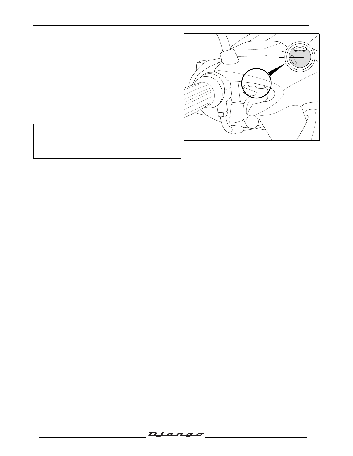
Checking the brake fluid level
- Position the handlebars so that the master
cylinder will be horizontal.
- Check the brake fluid level and if necessary top
up in the master cylinder.
- Remove the master-cylinder cover. See:
Procedure 10. page 25.
- Remove the cover and the diaphragm from the
master cylinder (2 screw).
Add brake fluid until it reaches the
maximum level.
LOW
MIN
Page 61
SERVICE OPERATIONS
60
Reproduction or translation, even partial, is forbidden without the written consent of Peugeot Scooters
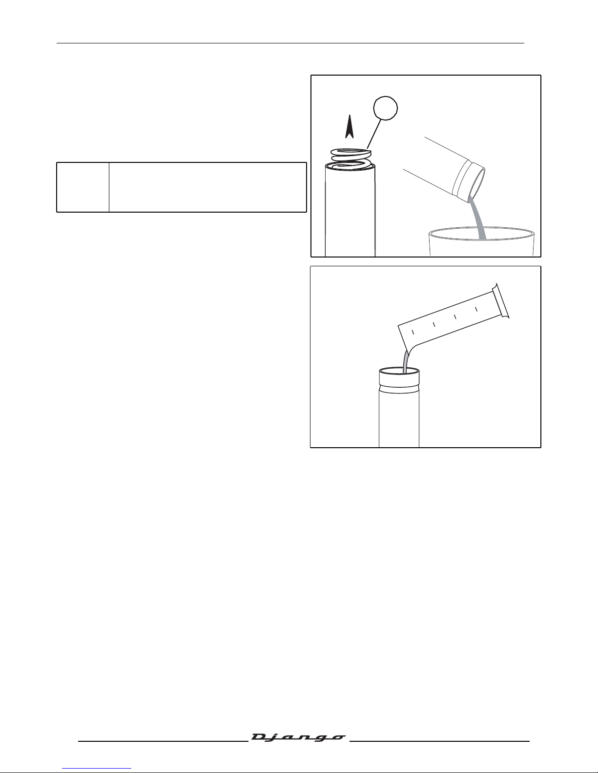
Draining the front fork
- Remove the fork tubes. See chapter : Changing
the front fork seals, page 61.
- Remove the fork tube cap (A).
- Remove the spring (C).
Turn the fork tube upside down to drain the
oil into a recipient.
- Pour 0.092l SAE10W hydraulic oil into the fork
tube.
- Refit the other items in the reverse order to
disassembly.
- Repeat the operation with the other stanchion.
C
Page 62
STEERING/FORK
61
Reproduction or translation, even partial, is forbidden without the written consent of Peugeot Scooters
STEERING/FORK
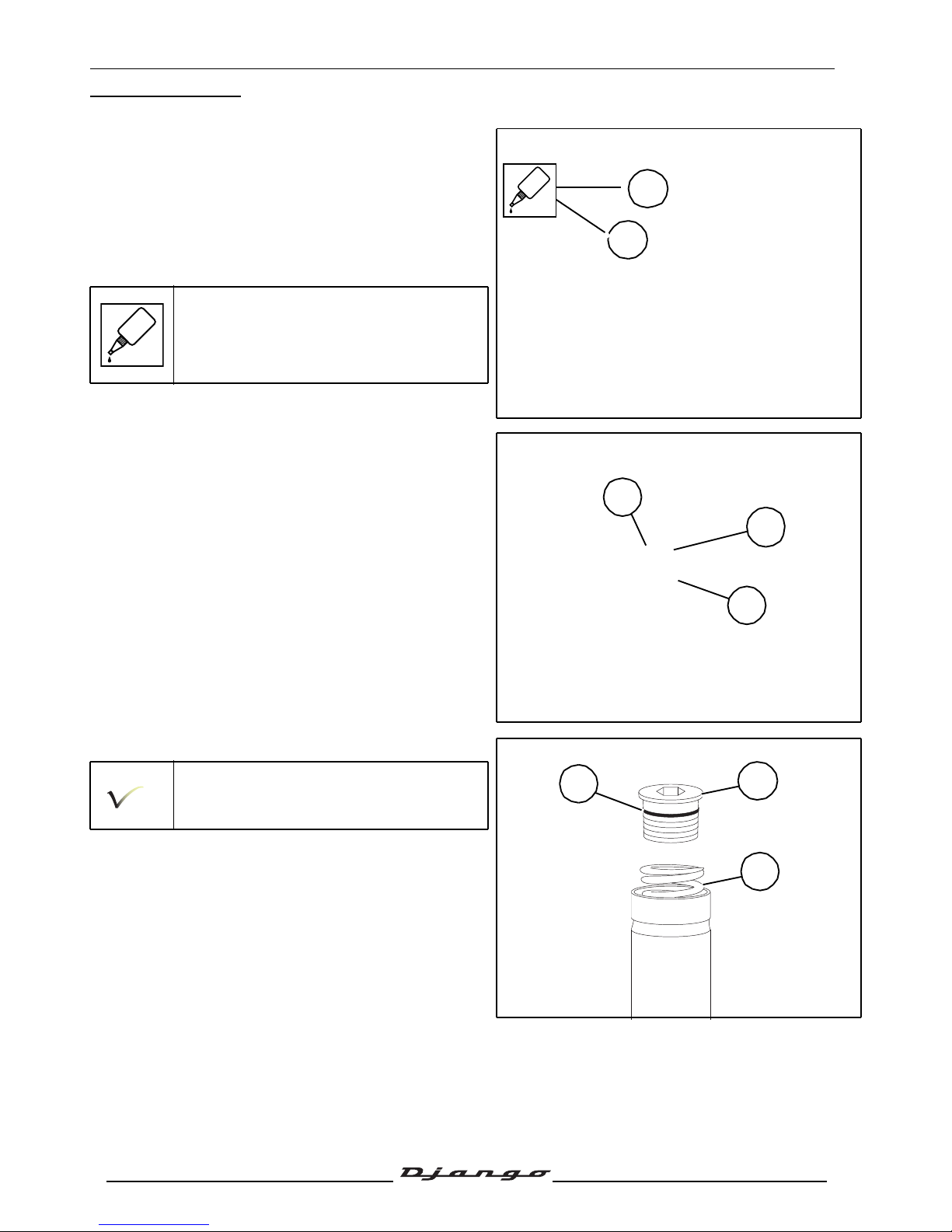
Changing the front fork seals
- Remove the front mudguard. See: Procedure 17.
page 29.
- Remove the brake caliper without disconnecting
it.
• 2 Ø 8 mm screw.
When refitting the brake caliper, spread
standard thread lock on the bolts.
- Unscrew and remove the 2 upper screws(1) from
the fork Tee.
- Before, loosen the fork tube caps (A).
- Unscrew the 2 lower screws (2) from the fork
Tee.
- Remove the fork stanchions.
- Remove the fork tube cap (A).
Check the condition of the O-rings(B).
- Remove the spring (C).
- Drain the front fork. See chapter : Draining the
front fork, page 60.
GLUE
GLUE
2
A
1
A
B
C
Page 63
STEERING/FORK
62
Reproduction or translation, even partial, is forbidden without the written consent of Peugeot Scooters
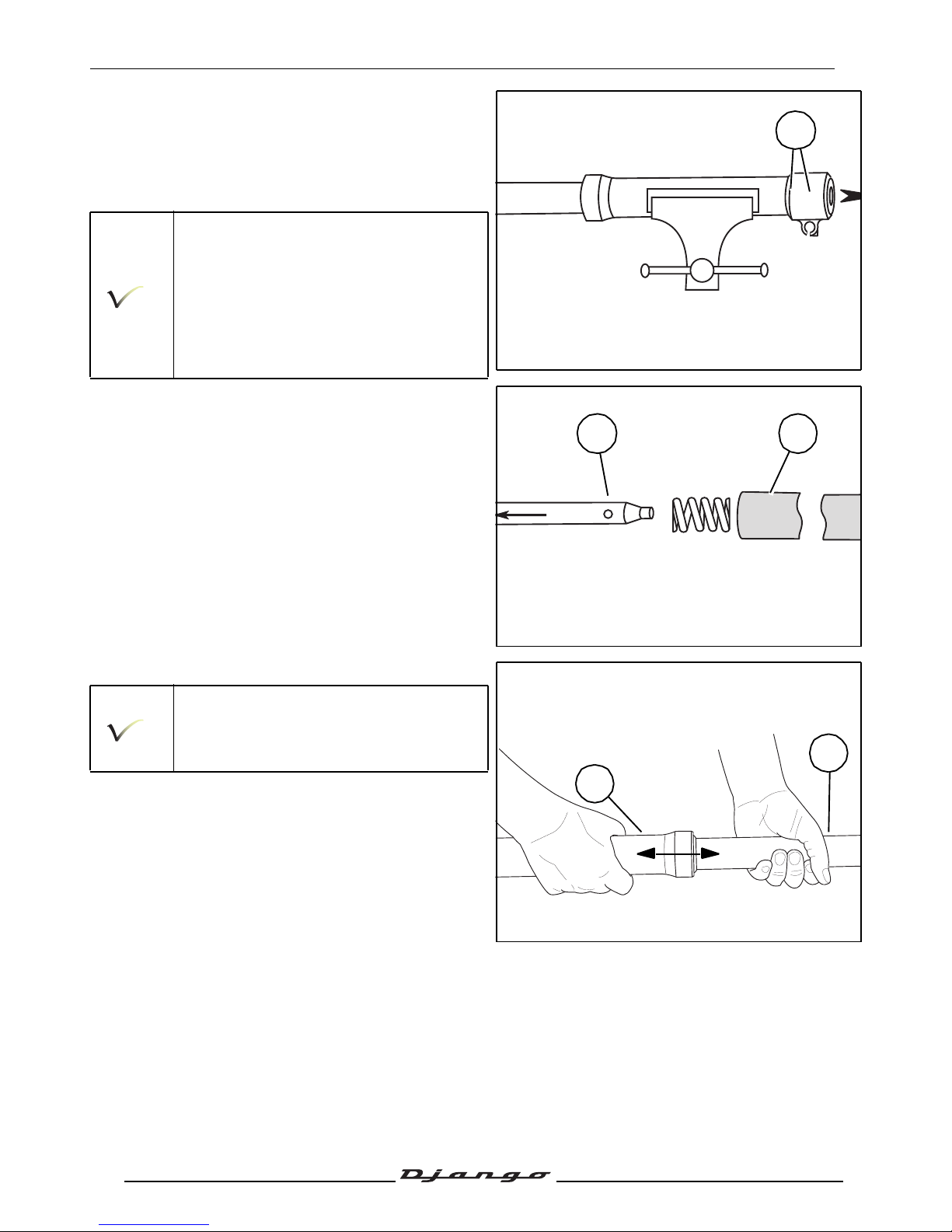
- Secure the stanchion in a vice fitted with
protection.
- Remove the tightening screw from the internal
tube and its seal (LM).
- If necessary use a mallet to dislodge the
screws.
If the screw is hard to remove, temporarily
refit the spring and the plug. Get someone
to help you and compress the fork unit to
block the calibrated hydraulic tube.
- Remove the calibrated hydraulic tube (D).
- Remove the expansion stop spring (E).
- Separate the fork's tube (F) from the cover (K).
Gently work the tube free from the hollow
shaft whose lip seal, washer and guide ring
should still be in place.
Operation that can be difficult.
LM
ED
K
F
Page 64
STEERING/FORK
63
Reproduction or translation, even partial, is forbidden without the written consent of Peugeot Scooters
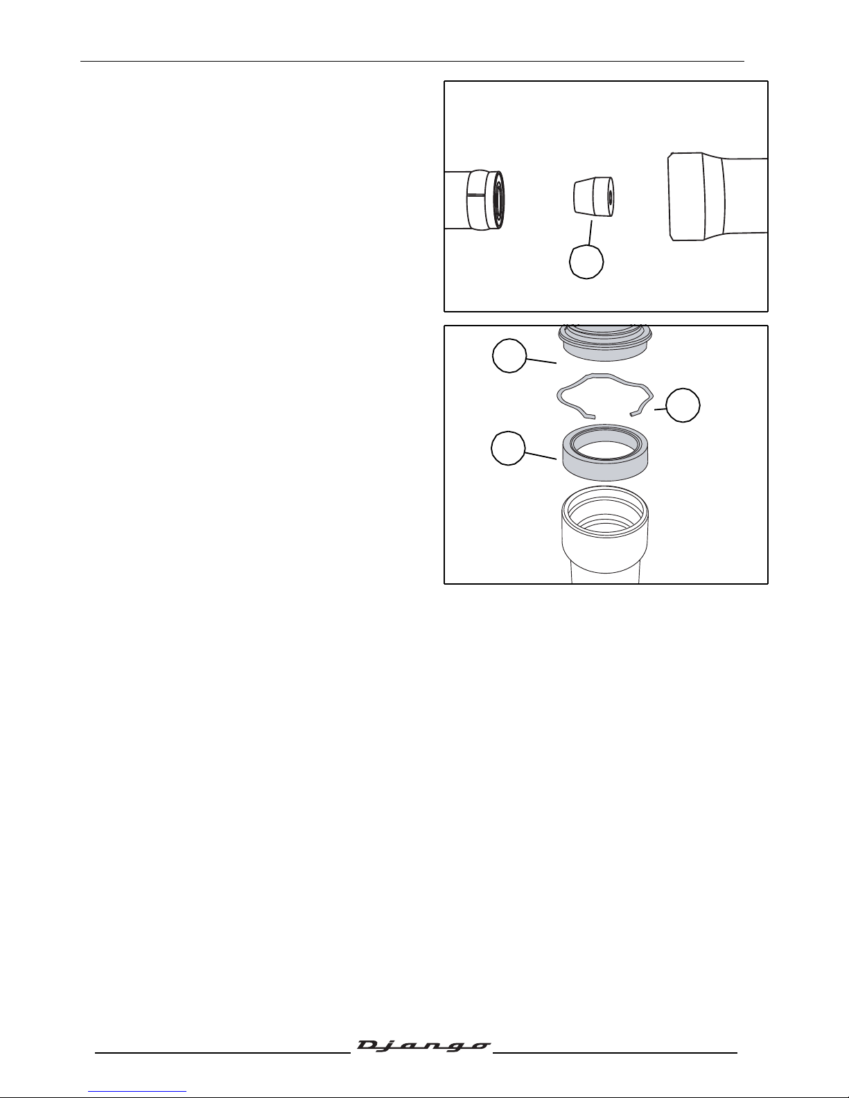
- Remove the compression stop cone (G).
- Remove the dust cover (H).
- Remove the retaining clip (I).
- Remove the seal (J).
G
J
H
I
Page 65
STEERING/FORK
64
Reproduction or translation, even partial, is forbidden without the written consent of Peugeot Scooters
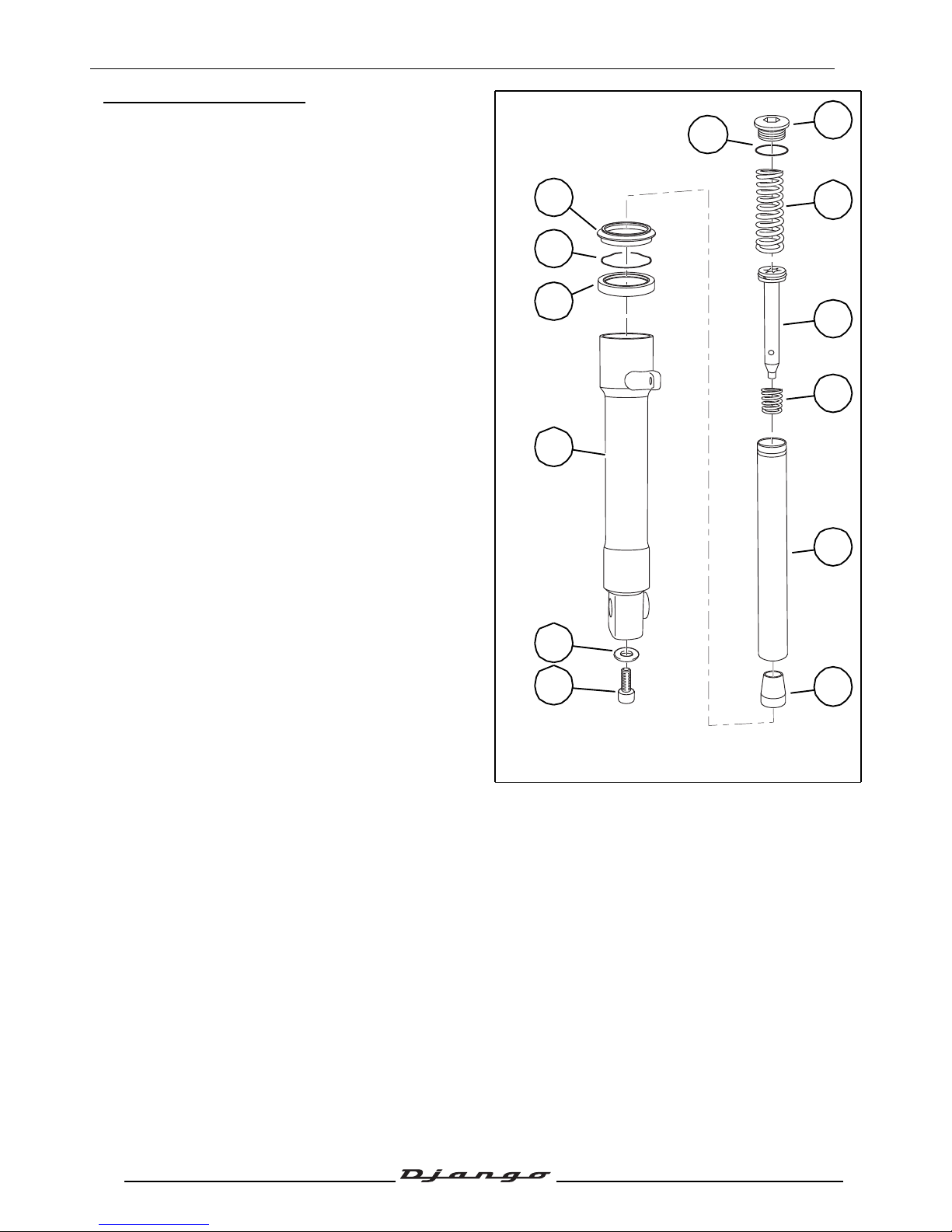
The fork and its components
A. Fork tube cap.
B. O-ring.
C. Spring.
D. Calibrated hydraulic tube.
E. Expansion stop spring.
F. Fork tube.
G. End of compression cone.
H. Dust cover.
I. Retaining clip.
J. Tightness seal.
K. Hollow shaft.
L. Tightness seal.
M. Stanchion assembly screw.
Pre-assembly checks
- Clean all the parts with a degreasing agent:
• Biosane type ref. 754748.
• Or use an ultrasonic cleaning tank.
- Check the condition of the fork tube, there shall be no corrosion or impact marks, and the tube shall
be perfectly straight and clean.
A
H
B
C
D
E
F
G
I
J
K
L
M
Page 66
STEERING/FORK
65
Reproduction or translation, even partial, is forbidden without the written consent of Peugeot Scooters
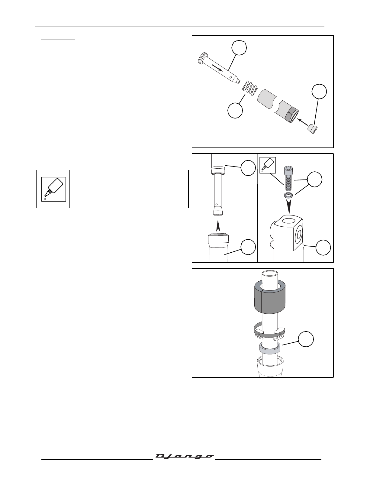
Reassembly
- Install the expansion stop spring (E).
- Install the calibrated hydraulic tube (D).
- Install the compression stop cone (G) on the
calibrated hydraulic tube.
- Fit the fork sleeve(K) to the slightly oiled fork
tube(F).
Install the stanchion assembly screw and
its seal (LM).
Tightening torque: 25 Nm.
- Using the marolotest lip seal insertion kit tool,
push the seal(J) under the groove in the
retaining ring.
D
E
G
F
K
LM
K
GLUE
GLUE
J
Page 67
STEERING/FORK
66
Reproduction or translation, even partial, is forbidden without the written consent of Peugeot Scooters
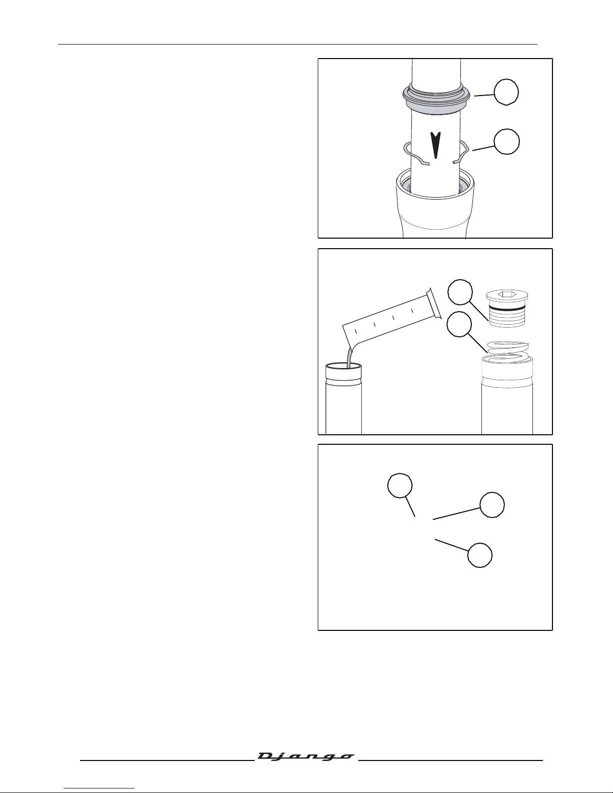
- Install the retaining ring (I).
- Fit a new, lightly greased dust cover (H).
- Pour 0.092 l SAE10W hydraulic oil into the fork
tube.
- Install the spring (C).
- Fit the fork tube cap (A).
Tightening torque: 28 Nm.
- Fit the fork tubes into the fork triple clamps.
- Fit and tighten the upper screws on the fork
tee (1).
Tightening torque: 28 Nm.
- Tighten the lower screws on the fork tee (2).
Tightening torque: 28 Nm.
H
I
A
C
2
A
1
Page 68
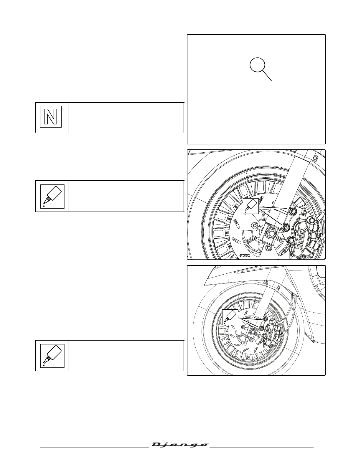
STEERING/FORK
67
Reproduction or translation, even partial, is forbidden without the written consent of Peugeot Scooters
- Fit the front mudguard.
- Fit the speedometer drive gear assembly to the
wheel drive pins.
- Fit the wheel, matching the speedometer drive
gear assembly to the pin(A) on the fork
stanchion.
- Fit the wheel spindle and tighten.
Tightening torque: 65 Nm.
When re-installing, use a new nut.
- Fit the brake calliper.
• 2 Ø 8 mm screws.
Tightening torque: 30 Nm.
When refitting the brake caliper, spread
standard thread lock on the bolts.
Removal of the fork
- Remove the front mudguard. See: Procedure17.
page29.
- Remove the brake caliper without disconnecting
it.
Tightening torque: 30 Nm.
When refitting the brake caliper, spread
standard thread lock on the bolts.
A
GLUE
GLUE
GLUE
GLUE
Page 69
STEERING/FORK
68
Reproduction or translation, even partial, is forbidden without the written consent of Peugeot Scooters
- Unclip the hydraulic controls and the speedometer
control.
- Remove the speedometer fairing. Voir:
Procedure 11.page 26
- Remove the handlebars from the fork tube.
(1 screws and 1 nut)(1).
Tightening torque: 40 Nm.
When re-installing, use a new nut.
- Using tool P/N 757860 remove the steering
locknut.
1
757860
Page 70
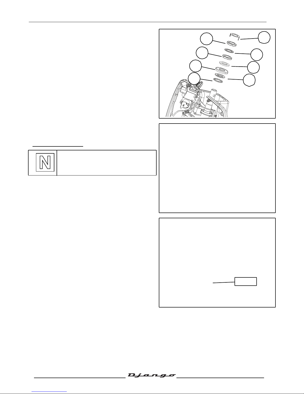
STEERING/FORK
69
Reproduction or translation, even partial, is forbidden without the written consent of Peugeot Scooters
- Remove:
• the lock washer (2).
• The nut (3).
• The rubber washer (4).
• The nut (5).
• The flat washer (6).
• The dust cover (7).
• The upper cone (8).
• Remove the caged ball bearings (9).
- Remove the fork.
Replacing the bearings of the steering
system
Steering headset cups
If the steering head cups are changed, the
cones and ball bearings must also be
changed.
- Using a drift, remove the steering head cups.
- Install new steering head cups using tool
P/N 759788.
2
3
4
5
7
9
6
8
759788
Page 71
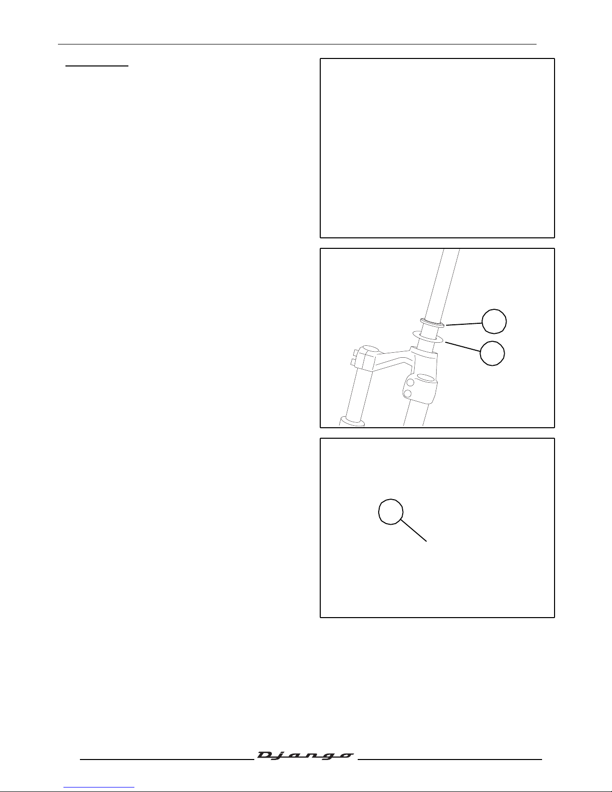
STEERING/FORK
70
Reproduction or translation, even partial, is forbidden without the written consent of Peugeot Scooters
Steering cone
- Tap out the steering cone using a drift placed
behind the flat washer.
- Install the following new parts:
• The flat washer (1).
• The fork cone (2).
Installing the fork
- Grease the cup bearing races.
- Install new ball cage bearings (7) (respect the
right way of installation).
- Fit the fork into the steering column.
2
1
7
Page 72
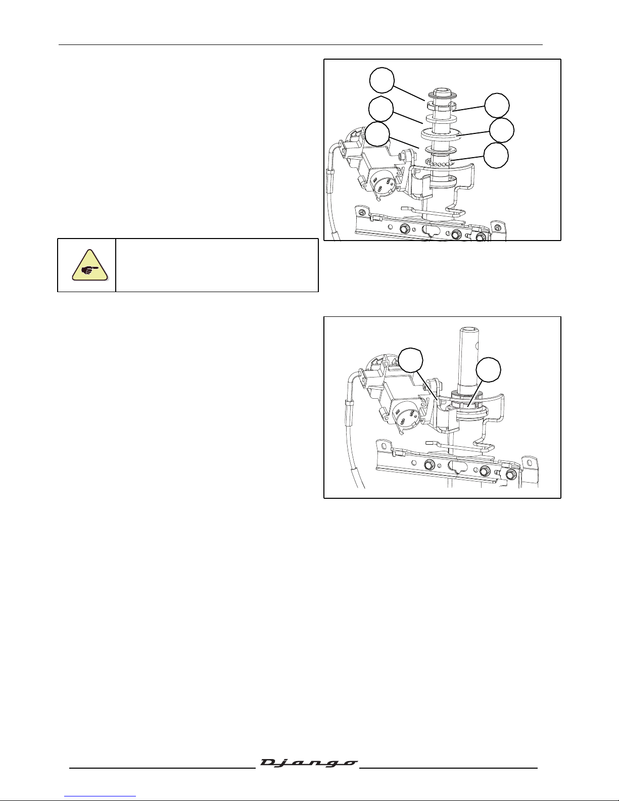
STEERING/FORK
71
Reproduction or translation, even partial, is forbidden without the written consent of Peugeot Scooters
- Install new ball cage bearings (no special
direction).
- Install the upper cone (8).
- Install the dust cover (7).
- Fit the plain washer (6).
- Fit the first nut (5).
Tightening torque: 40 Nm.
- Loosen and re-tighten the steering head nut (5).
Tightening torque: 18 Nm.
- Install the rubber washer (4).
Do not tighten the steering nut beyond the
recommended value to avoid damanging
the steering bearings.
- Fit and finger tighten the nut (3) so that its notches
are aligned with those of the nut.
- Fit the lock washer (2) in the notches of the
locknut and adjustable cone.
- Install the steering head locknut and tighten it.
Tightening torque: 75 Nm.
- Check that there is no play in the fork.
- Turn the fork from left to right to check that there
are no tight spots.
- Refit the other items in the reverse order to
disassembly.
8
9
7
6
4
5
3
2
Page 73
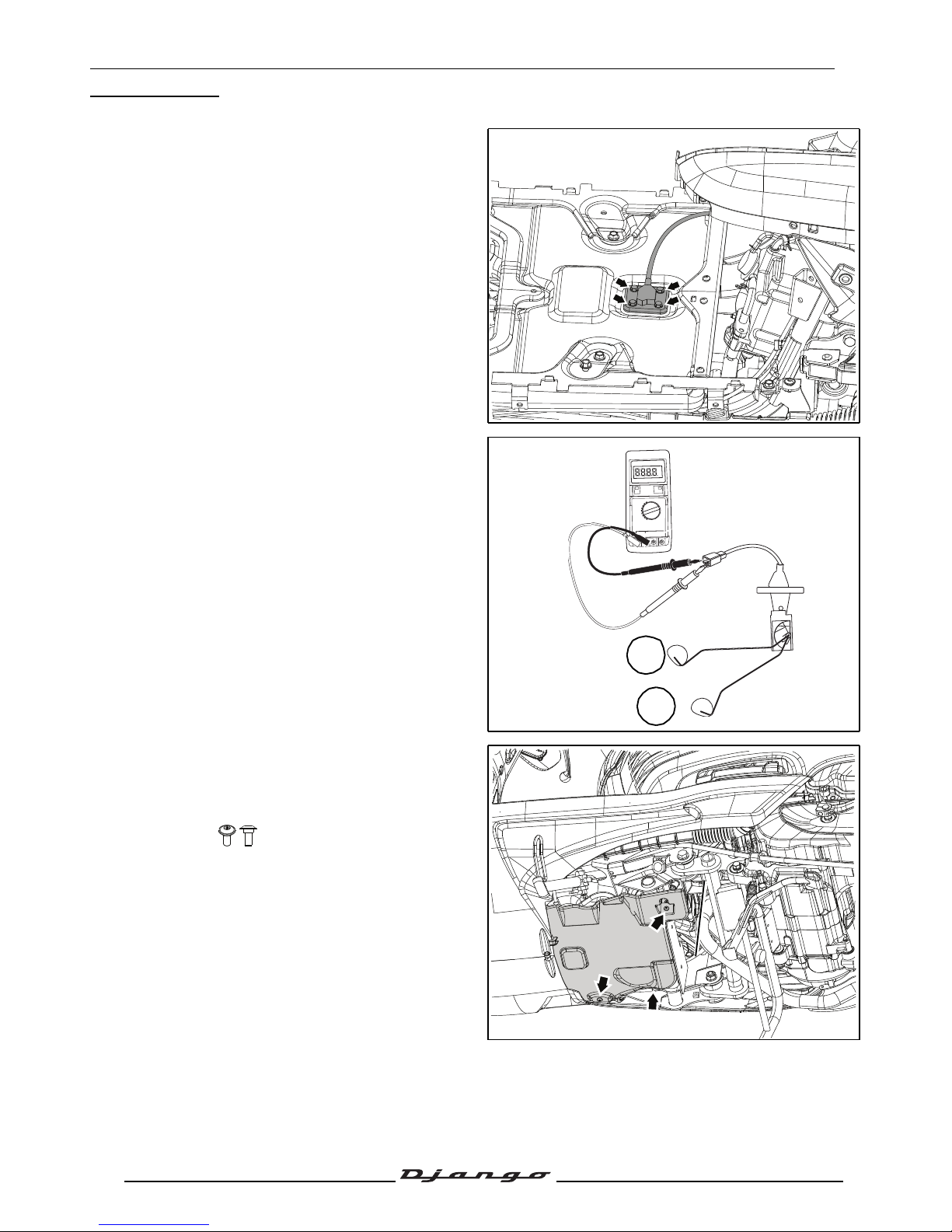
FUEL SYSTEM
72
Reproduction or translation, even partial, is forbidden without the written consent of Peugeot Scooters
FUEL SYSTEM
Removal of the fuel gauge
- Remove the footboard. See: Procedure 12.
page 26.
- Remove the fuel gauge.
• 4 Ø5 mm screw.
Fuel gauge check
A. Full fuel tank: 10 Ω
±20%
B. Empty fuel tank: 95 Ω
±20%
Removal of the fuel pump
- Remove the protective shoe.
• 3 screw.
Ω
A
B
Page 74
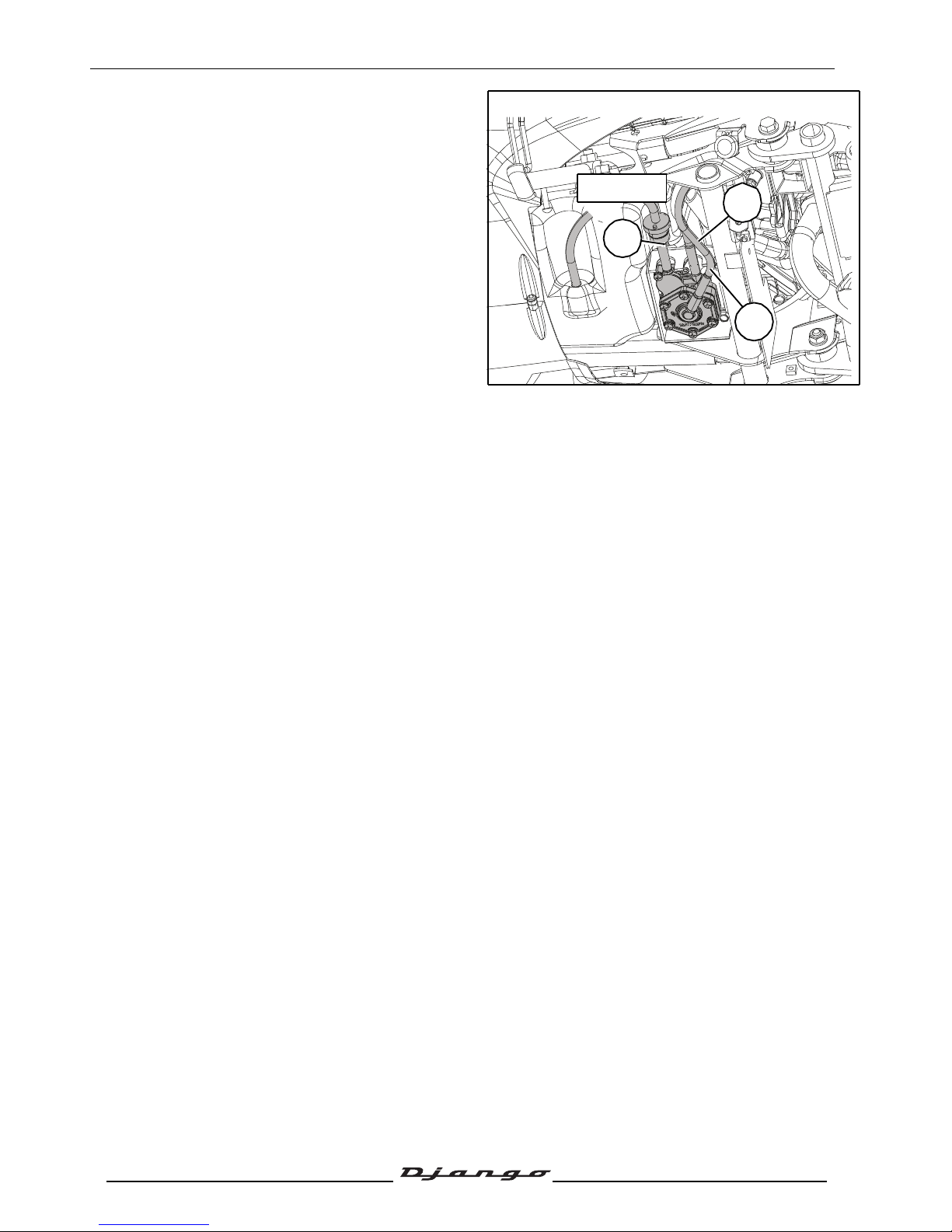
FUEL SYSTEM
73
Reproduction or translation, even partial, is forbidden without the written consent of Peugeot Scooters
- Using tool part number 755996 clamp the fuel
supply hose between the tank and the fuel
pump.
- Disconnect the fuel pump:
1. The vacuum pressure hose.
2. The fuel inlet pipe.
3. The carburetor fuel supply hose.
1
2
3
755996
Page 75
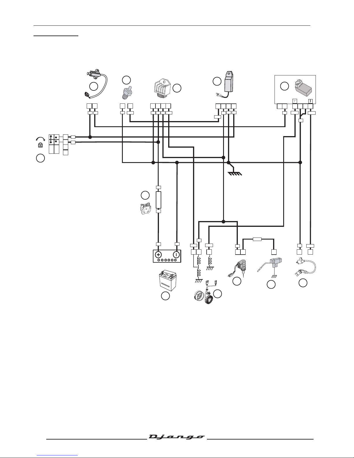
ELECTRICITY
74
Reproduction or translation, even partial, is forbidden without the written consent of Peugeot Scooters
ELECTRICITY
Ignition principle schematic/Carburetor heater/Battery charge circuit
1. Ignition switch.
2. Kickstand contact switch.
3. Resistor warming carburator.
4. Voltage regulator.
5. Temperature control unit.
6. Ignition unit.
7. HT coil.
8. Starter resistor.
9. Automatic starter.
10.Magneto flywheel.
11.Battery.
12.7.5A fuse
7.5A
F1
OFF
ON
2
1
4
3
X
X
RG
VE
RG
RG
VE
VE
VE-BA
VE
JN
NR
VE
VE-NR
JN
JN-NR
VE
RG
NRNRNR
NR
VE-NR
JN-NR
JN-BA
JN-BAJN-BA
JN-BA
JN
JN
RG
8
10
6
11
12
1
9
7
2
3
5
4
Page 76
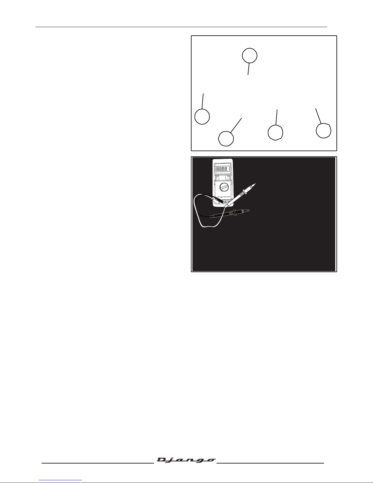
ELECTRICITY
75
Reproduction or translation, even partial, is forbidden without the written consent of Peugeot Scooters
Regulator/Temperature control
unit/Starter motor relay/CDI unit/Starter
resistor
- Remove the upper RH fairing. See:
Procedure 6. page 21.
- Removal:
• Regulator (1)
• The starter motor relay (2)
• The temperature control unit (3)
• The ignition module (4)
• The starter resistor (5)
Checking the ignition system
Disconnect the ignition unit and take the
measurements on the harness side.
- Between the green wire and the ground: 0 Ω.
- Between the green/black wire and the ground
(Ignition sensor) : 195 Ω
±20%
.
- Between the yellow/black wire and the earth
(High voltage primary coil) : 0.5 Ω
±20%
.
- Between the black wire and the ground, ignition
on: 12V (Battery voltage).
If the values are correct, replace the ignition
module.
If the values are incorrect, check:
- The harness.
- The ignition switch.
- The kickstand contactor.
- The high voltage coil:
• Primary: 0.5 Ω
±20%
.
• Secondary: 3.7 KΩ
±20%
.
• Spark plug socket: 5 KΩ
±20%
. Low voltage
coil:
- The ignition sensor: Between the green/black
wire and the ground: 195 Ω
±20%
.
3
4
1
5
2
Ω
Page 77
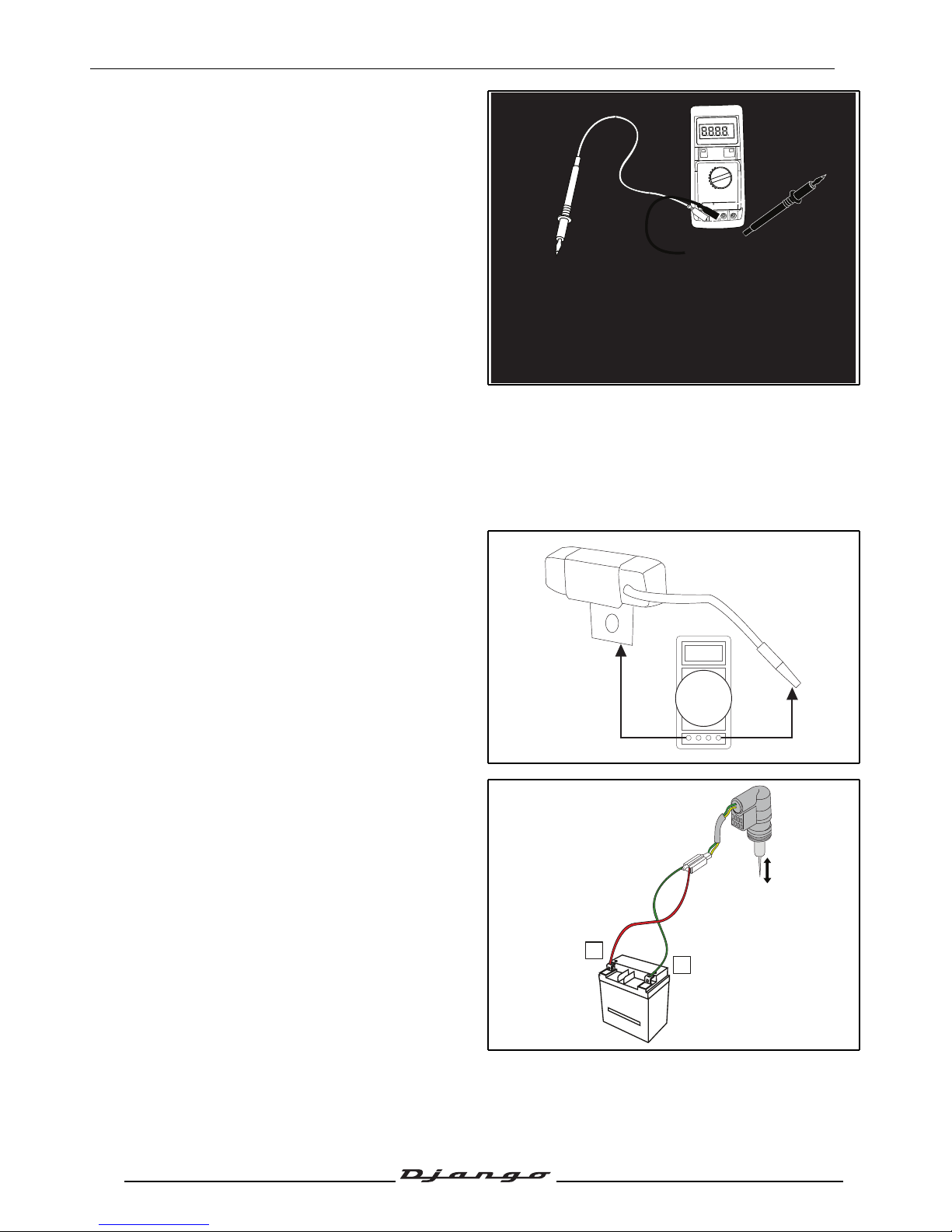
ELECTRICITY
76
Reproduction or translation, even partial, is forbidden without the written consent of Peugeot Scooters
Checking the carburettor heating circuit
Power supply range of the carburettor heating
resistor:
between 10±2 and 20±2 °C.
Disconnect the temperature control unit and
take the measurements on the harness side.
- Between the green wire and the ground: 0 Ω
- Between the white/yellow wire and the ground
(Resistor warming carburator):9.5 Ω
±20%
.
- Between the black wire and the ground, ignition
on: 12V (Battery voltage).
- Between the yellow wire and the ground, engine
running: 13.5V (Regulated alternating current).
If the values are correct, replace the
temperature control unit.
If the values are incorrect, check:
• The harness.
• The ignition switch.
• The carburettor heating resistor : 9.5 Ω
±20%
.
Checking the starter circuit.
Checking the starter resistance:
- Disconnect the limiting resistance.
- Measure the value of the resistance between
the resistor wire and the earth: 5 Ω
±20%
.
Checking the electric starter
- Removal of the electric choke.
- Connect the starter to a battery. The starter
piston should retract.
Ω
Ω
-
+
Page 78
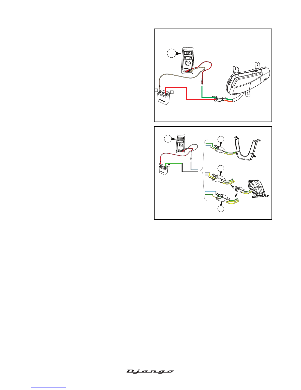
ELECTRICITY
77
Reproduction or translation, even partial, is forbidden without the written consent of Peugeot Scooters
Checking the indicators
- Removing an indicator.
- Connect the indicator in series with a battery
and a ammeter.
Normal consumption: 0.30 - 0.40 A.
- If consumption is outside this range, change the
indicator.
- Carry out the same operation with the other
indicators.
- If the consumption of the indicators is correct,
check the wiring harness.
Checking the red light, the stop light and
the side light
- Remove the side light or the rear light.
1. Connect the side light in series with a
battery and an ammeter.
Normal consumption: 0.25 - 0.35 A.
2. Connect the stop light in series with a
battery and an ammeter.
Normal consumption: 0.25 - 0.35 A.
3. Connect the red light in series with a battery
and an ammeter.
Normal consumption: 0.60 - 0.70 mA.
- If the consumption is outside this range, change
the side light or the rear light.
- If the consumption of the side light or the rear
light is correct:
Check:
• The main harness.
• The stop light contactors.
• The magneto.
• The regulator.
+
OFF
VDC
VAC
Ω
20 m
200 m
DC
10A
VΩ
COM
mA
A
-
+
OFF
VDC
VAC
Ω
20 m
200 m
DC
10A
VΩ
COM
mA
A
3
2
1
Page 79
POWER UNIT
78
Reproduction or translation, even partial, is forbidden without the written consent of Peugeot Scooters
POWER UNIT
Removal of the power unit
Note: To remove the cylinder head, remove the power propulsion unit.
For removal of the cylinder head, cylinder and piston, see the workshop
manual : MA0020/MA0050.
- Remove the storage compartment. See: Procedure 2. page 20.
Disconnect:
• The carburettor heater (1).
• The choke (2).
• The magneto (3).
• The starter motor (4).
• The engine ground (5).
• The suppressor (6).
- Disconnect:
• The throttle control (7).
• The fuel hose (8).
• The vacuum pressure hose (9).
4
5
6
1
2
3
7
8
9
Page 80
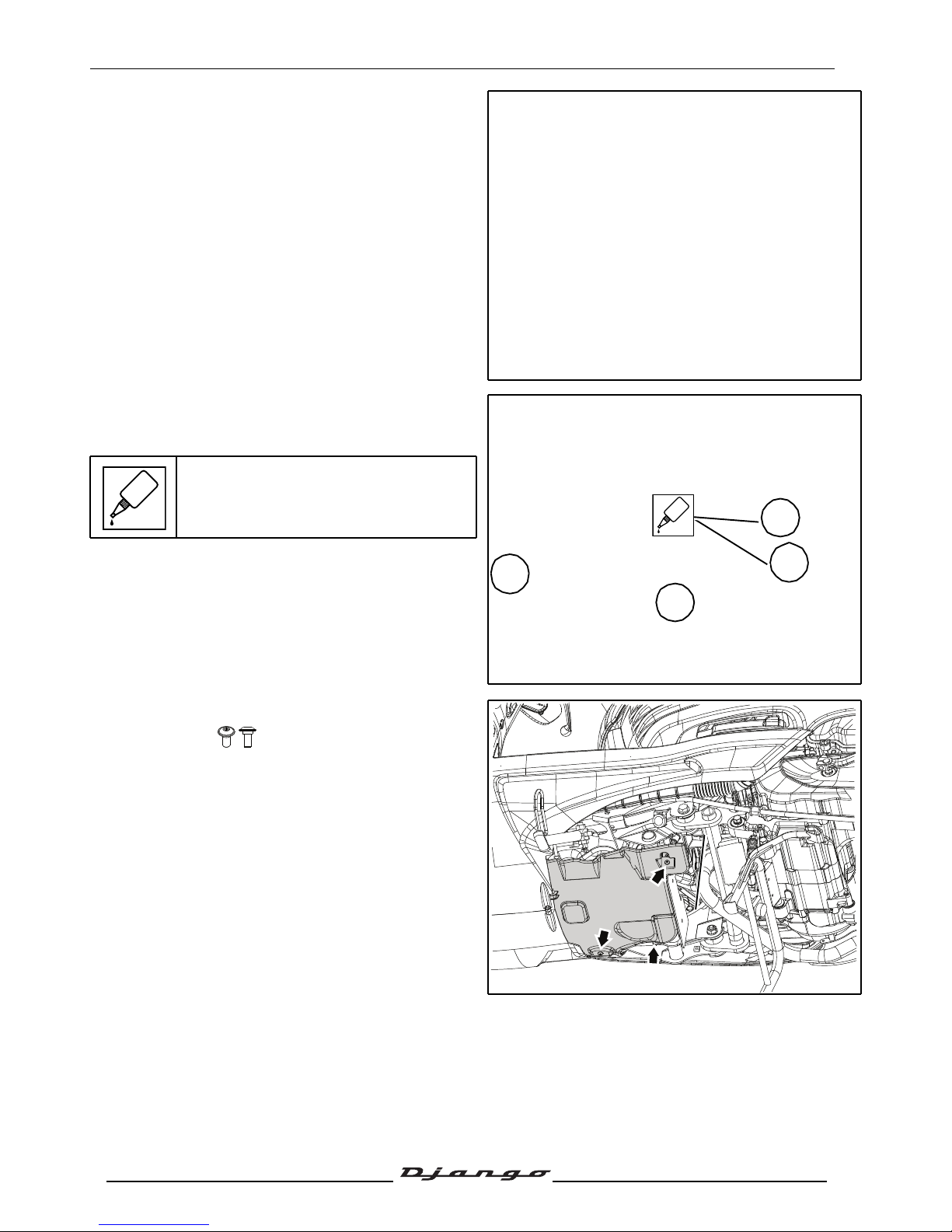
POWER UNIT
79
Reproduction or translation, even partial, is forbidden without the written consent of Peugeot Scooters
- Remove the wheel trim.
- Remove the wheel (5 screw).
Tightening torque: 30 Nm.
- Remove the brake calliper (2 screw).
Tightening torque: 30 Nm.
When refitting the brake caliper, spread
standard thread lock on the bolts.
- Unclip the hydraulic control.
- Temporarily reinstall the wheel.
- Remove the protective shoe.
• 3 screw.
GLUE
GLUE
Page 81
POWER UNIT
80
Reproduction or translation, even partial, is forbidden without the written consent of Peugeot Scooters
- Remove the passenger seat. See: Procedure 1.
page 20.
- Remove the battery cover.
- Disconnect and remove the battery.
- Suspend the rear of the machine.
- Remove the hatch giving access to the shock
absorber upper screw (1).
- Remove the shock absorber upper fixing bolt.
Tightening torque: 48 Nm.
• Remove the 2 connecting-rod/chassis
fastening screws (2).
Tightening torque: 60 Nm.
Use new nuts when refitting.
1
2
2
Page 82
POWER UNIT
81
Reproduction or translation, even partial, is forbidden without the written consent of Peugeot Scooters
- Remove the power propulsion unit from the
frame.
- Remove the covers from the power unit.
Page 83
P/N. MA0051GB
In our permanent concern to make improvements PEUGEOT Scooters reserves the right to suppress, modify,
or add any reference mentioned.
DQ/APV Printed in E.U. July 16, 2014. (non contractual pictures)
 Loading...