

PEUGEOT Coupe 406 Handbook


3
• Contents
• ALPHABETICAL INDEX . . . .. .
4
to
5
• EQUIPMENT - COMFORT - SAFETY 7 to
51
• SETTING OFF - DRIVING.. .. .. .. .. . . .
53
to
70
• INTERIOR EQUIPMENT AND LOADING
71
to
75
• MAINTENANCE.. . . . .. . . . .. . .. . .. . .. 77 to
87
• RECYCLING AND THE ENVIRONMENT . . . . . . . . . . . . . . . . . . . . . . . ...
89to91'
• BASIC REPAIRS . . . . . . . . . . . . . . . . . . . . . . . . . . . . . . . . . . . . . . . . . . . . . . . . . . . . . . . . . . . . . . . .
93
to
111
• TECHNICAL DATA
113
to
117
• RADIO/CASSETTE/CD
119
to
161
• LUBRICANTS AND ACCESSORIES
163
to
166
• ALARM SYSTEM. . . .. .. . .. . . . . . . . . . . . . .
167
to
169
Pages
The functions described in this document may vary according to the specification and destination of your vehicle.
4
ALPHABETICAL INDEX
.................
~
.
A ABS .. 60
Access to rear seats. . .72-73
Accessories. . . . . 166
Adjustable steering wheel '.. 27
Adjusting seat belts . . . . 38
Adjusting seats 71 to 75
Airbags . . . . . . . . . . . . . 40-43
Air conditioning. . .. 32-38
Air filter. . . . . . . . . . . . . . . . . 66-83
Air recirculation . . 32 to 37
Alarm system. . . . . 167 to 169
Armrests. . . . . . . . . . .... 74
Ashtrays. .. . 49
Audio 4030 .119 to 136
Audio 4050 .......•..... 137 to 161
Automatic gearbox .. 61 to 63
B Battery.. . . 83-100-101
Battery charge (waming light) ... 22
Battery failure. . . 100-101
Bodywork maintenance 86-87
Bonnet (opening) 12
Brake light (additional) 46
Brakes. . . . .60-67-82
Bulbs (replacement) ... 102 to 104
C Capacities........ . 114
Catalytic converter 15
Chains .. . . . . . . . . . . . . . .. - 84
Changing a wheel. . . 106-107
Changing bulbs. . .. 102 to 104
Checks before setting off . . .. 54
Child safety. . . 39
C Child seats. . . . . . . . . . . . . 39
Coat hooks. . 49
Coded anti-start. . .. 55 to 57
Coin storage. . . . . ... 48
Consumption . . . . . . . . . . 115
Coolant temperature gauge 22
Cooling circuit. . . . .. 82
Courtesy lights. . . ... 46
Courtesy mirror. . . .. 47
Cruise control. . . . ... 65
F Filling up with fuel. . . . 13
Fitting loud speakers . 51
Fog lights . . . 24
Folding rear seats 75
Front airbags. . . . 40-41
Front seat belt pretensioners 38
Front seats .. 72-73
Fuel. . . . . ... 13 to 15
Fuel gauge . 18 to 20, 23
Fuel economy. . . . . . .... 66
Fuel filler flap. . . . . . 13
Fuel quality. . . 14
Fuel supply cut-off switch. . . . 13
Fuses. . . .. 94 to 99
D Deadlocking (locking) .. 8-9
Demisting - de-icing .. 30-31
Digital clock. . . . . . . . . . . . . . . .47
Dimensions. . . 116
Dipped headlights. . .. 24
Direction indicators. . .. 25
Door sill lighting . . . . . . . . . ... 46
Doors. . . .. 10
Driving 66 to 68
E Electric central locking . . . 8
Electric windows. . 44
Electronic suspension 64
Engine oil. . 82-164-165
Engine oil gauge. . .. 21
Engine oil temperature
and level gauge. . .. 21
Engine:
2 litre 16 valve 78-79
V6 injection 24 valve. . 80-81
Exterior air temperature display 49
Exterior mirrors. . . . . . . . . . .. 29
G Glove compartment
... 48
H Handbrake.. . .. 60
Hazard warning lights. . .... 25
Headlight adjustment. . .. 102
Headlight wash 26
Headlights (control) . . . . . . . . . 24
Headrests. . . 72
Heated mirrors. . . .. . 29
Heating and ventilation . 30 to 37
Horn. . . . . . . . . . . . . . . . . .. 25
Ignition 58
Instrument panel. . 16 to 20
Instruments and controls 16 to 29
Interior lighting. . . . ..... 46
ALPHABETICAL INDEX
Interior mirror. . . . . . . . . . . .. . .... 28
J Jack .................•.... 106-107
K Keys 8
L Levels and checks 78 to 83
Lighting. . . . . . . . 24
Lighting rheostat 46
Lighting stalk . . . . . . . .. . 24
Locking (coded anti-start) 55 to 57
Locking doors. . 8 to 10
Locking the rear seat 75
Loud speakers. . . . . . 51
Lubricants. . . . . . . . . . . . . 164-165
Luggage compartment. . . 46
M Main beam headlights . . . 24
Manual gearbox 61
Mapreading light 46
o Oil filter 82
Opening the fuel filler flap 13
Openings. . . . . . . . . . . . . . .8 to 11
P Passenger compartment
maintenance 85
Pollen filter 31
Power steering 60
Punctures 106 to 109
R Radio 50-51
R Rain sensor 26
Rear screen demisting. . . 26
Rear seats 74-75
Rear parcel shelf . . . . . . . . . . . . . 48
Rear windows 45
Recycling 90
Regular checks 82-83
Remote control 9
Replacing a wheel . . . . . .. 106
Replacing bulbs 102 to 104
Replacing fuses . . . . . . . . . . . 94
Replacing remote control batteries 9
Replacing the battery 100
Reverse gear 61
S Safety advice . . . . . . . . . . . . . . 67
Seat belts . . . 38
Seats, electrical adjustment. . .... 73
Setting off 54 to 65
Side airbags ' 42-43
Sidelights 24
Signalling 24-25
Ski flap 74
Spare wheel 106
Spotlight 46
Starting 58
Steering wheel adjustment 27
Storage compartment 48
Sun roof 45
Sun visor 47
5
T Technical data 113 to 117
Temperature regulation 34 to 37
T Temporary spare wheel 106
Tilting the backrest 72-73
Tools............. . 106
Towing 68,110-111
Towing loads. . . . . . . . . . . . . . 114
Tyres 105 to 109
V Variable suspension '.' 64
Vehicle identification. . 117
Ventilation 30-31
Vents 30-31
W Warning lights. . . . ..... 18 to 23
Warning lights:
- Anti-lock braking system ABS 23
- Battery charge 22
- Central warning. . 21
- Engine auto-diagnostics 22
- Engine oil pressure 21
- Front airbags 23
- Front brake pad wear 23
- Handbrake 22
- Low brake fluid level 22
- Low coolant level 22
- Low windscreen wash level 23
- Side airbags . . . . 23
Washing 85 to 87
Weights 114
Wheel brace 106
Windscreen wash. . . . . . . . . . 26
Winter precautions 84
6
Openings and access
• Keys and remote control.
• Doors and boot ..
• Bonnet.
• Fuel filler flap and filling with fuel.
• Fuel quality.
• Catalytic converter ....
0 •• 0 •• 0 ••
.0.0.00 ••• 00.0.
'0' .00.
o'
0.00.
o.
00 •• 0 •••••
po
8
•••••• 0 •• 0.0 •••• 0 •• 0 •••••
po
10
••• 00. 0" 0 •••••
o.0o. o.
0"
o. • ••••
po
12
.. po
13
• •• 0 •••••••
o.0o.
0.00 •••
po
14
0 •••• 0 ••••••••
po
15
Instruments and controls
•••• 0o.0" 0o.0000.0.0 ••o.0 0 000. 0"
.po
17
• Dials. . . . . . . . . . . . . . . .
0 • • 0 • 0 •••• 0 •••••••••••
p,
18
• Warning lights. .
0 •• 0 •••••••• 0 0 • 0 0 •• 0 • 0 0 0 0 0 • 0 • 0 • 0 0 ••• 0 0 •• 0 •• 0
p.
21
• Indicators. . .. .
0 0 • 0 •••• 0 0 • 0 0 0 0 0 0 0 0 • 0 0 • 0 •••• 0 • • • • • ••
po
24
• Visibility. . . . .
0 •••• 0 •• 0 •••
po
26
• Adjusting the steering wheel
0 • 0 •• 0 • • • • ••• 0 ••
o. •
po
27
• Mirrors. . .
0 •• 0 • 0 •• 0 • • • 0 ••• 0 0 •• 0 •••
po
28
• Instruments and controls ....
Comfort and safety
• Ventilation
o ••
0 • • • • • ••••• 0 • • • • •
po
30
• Air conditioning.
0 ••••• 0 • • • • ••••• 0 • • •
p.
32
• Air conditioning with temperature and air flow regulation. . .po34
• Seat belts
0 • • • • • • • • • •• 0 • 0 • 0 • 0 0 • • •
p.
38
• Child safety
0 • 0 • 0 00. • 0 •• 0 • 0 • • •
po
39
• Front airbags . .
o' •
0 • • •• 0. 0 0 • • 0 •• 0 • 0 0 0 • 00.000.0.
p.
40
• Side airbags
0 • 0 0 0 0 • 0 0 •• 0 • 0 ••••••••• 0 • • • • •••••
p.
42
• Window controls. . .
0 •• 0 •••• 0 • • • • .00 ••••
p.
44
• Practical comfort. . . .
0 0 • 0 0 • 0 0 0 •• 0 • 0 0 00000 0 • 0 • • • 0 • 0 • 0 • • ••
p.
46
• Radio pre-equipment ....
0 •••• 0 •• 0 • 0 ••••• 0 • 0 • • • 0 •• 0 ••••
p.
50
7
EQUIPMENT
COMFORT - SAFETY
8
OPENINGS AND ACCESS: Keys
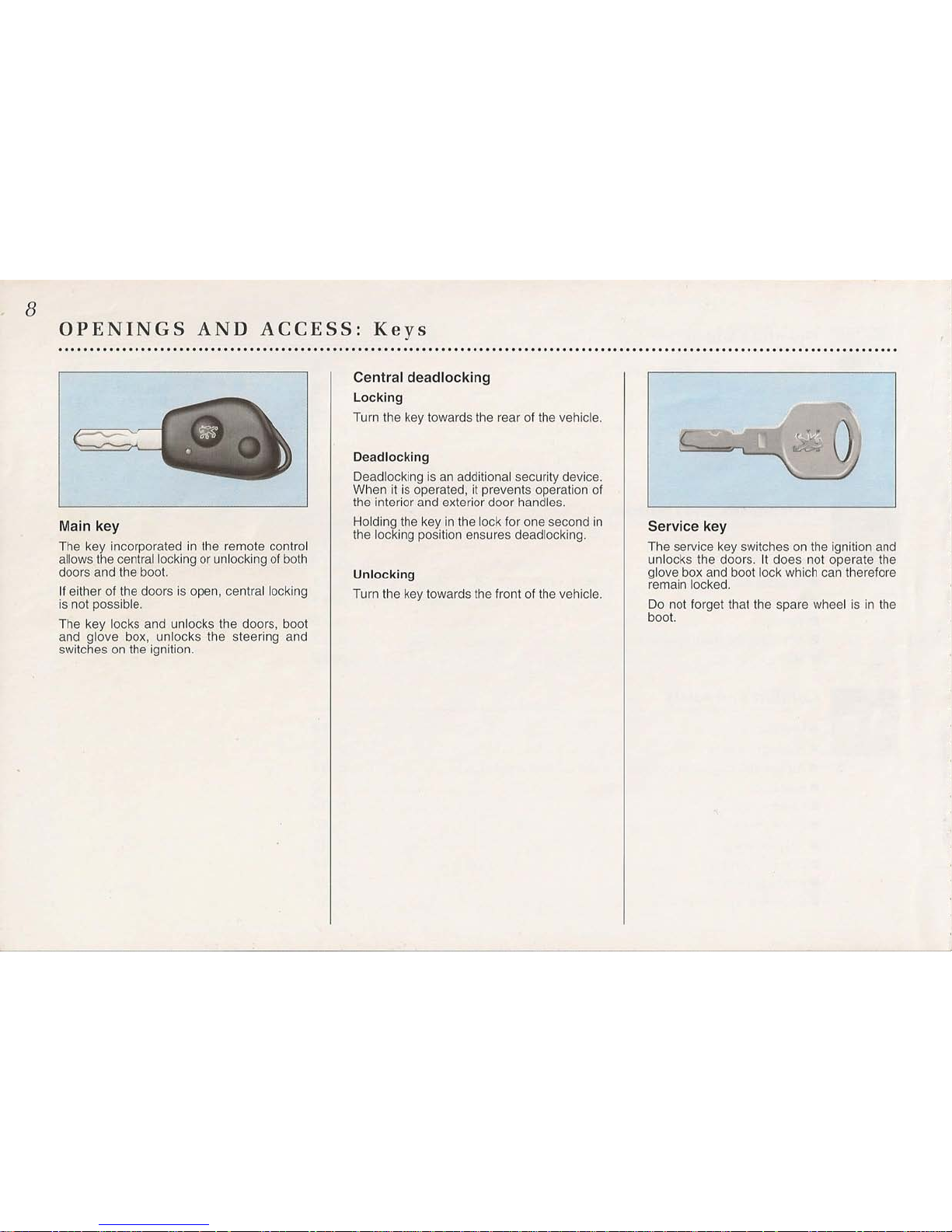
Main key
The key incorporated in the remote control
allows the central locking or unlocking of both
doors and the boot.
If either of the doors is open, central locking
is not possible.
The key locks and unlocks the doors, boot
and glove box, unlocks the steering and
switches on the ignition.
Central deadlocking
Locking
Turn the key towards the rear of the vehicle.
Deadlocking
Deadlocking is an additional security device.
When it is operated, it prevents operation of
the interior and exterior door handles.
Holding the key in the lock for one second in
the locking position ensures deadlocking.
Unlocking
Turn tile key towards the front of the vehicle.
Service key
The service key switches on the ignition and
unlocks the doors. It does not operate the
glove box and boot lock which can therefore
remain locked.
Do not forget that the spare wheel is in the
boot.
Remote control
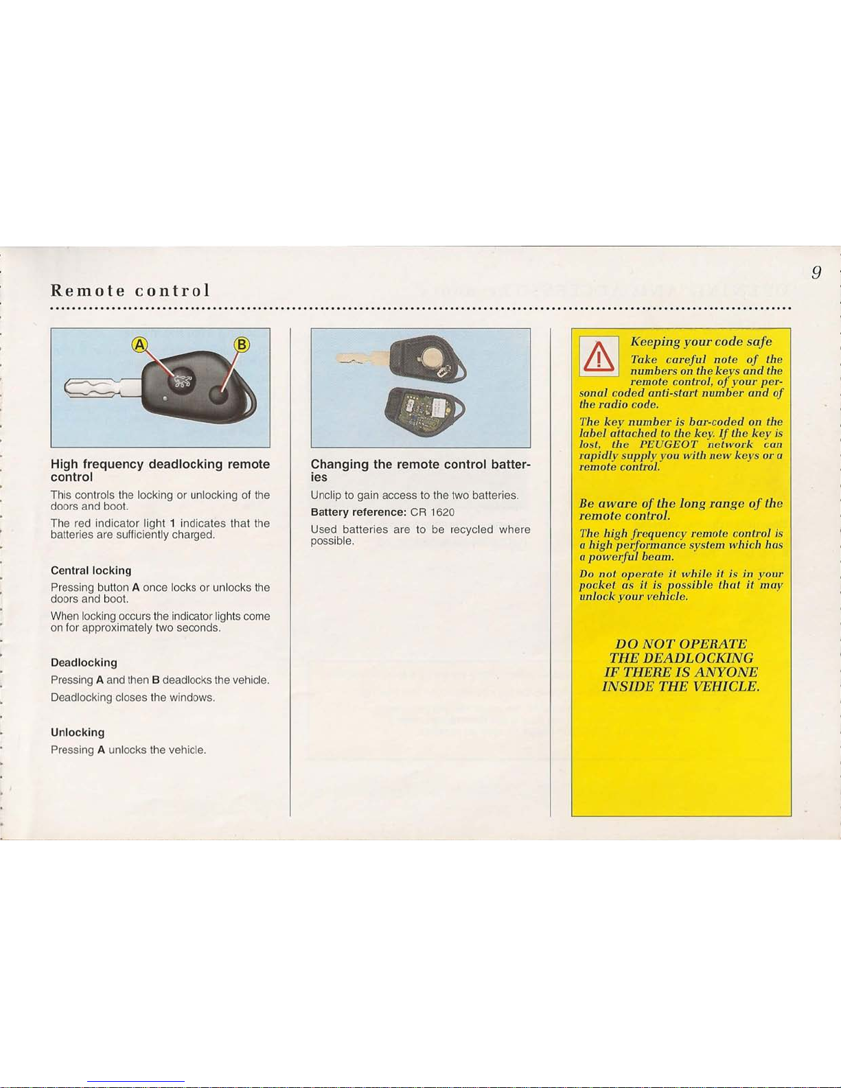
High frequency deadlocking remote
control
This controls the locking or unlocking of the
doors and boot.
The red indicator light 1 indicates that the
batteries are sufficiently charged.
Central locking
Pressing button A once locks or unlocks the
doors and boot.
When locking occurs the indicator lights come
on for approximately two seconds.
Deadlocking
Pressing A and then B deadlocks the vehicle.
Deadlocking closes the windows.
Unlocking
Pressing A unlocks the vehicle.
Changing the remote control batter-
ies
Unclip to gain access to the two batteries.
Battery reference: CR 1620
Used batteries are to be recycled where
possible.
9
I
/1\
I
Keeping your code safe
I
Take careful note of the
• numbers on the keys and the
remote control,oJyour per-
sonal coded anti-start number and of
the radio code.
The key number is bar-codedonthe
label attached to the key. If the key is
lost, the PEUGEOT network can
rapidly supply you with new keys
01'
a
remote control.
Be aware of the long range of the
remote control.
The high frequency remote control is
a
high performance system which has
a
powerful
beam.
Do
not operate it while it
is ill
your
pocket
as it is
possible thatitmay
unlock your vehicle.
DO
NOT OPERATE
THE DEADLOCKING
IF THERE IS ANYONE
INSIDE THE VEHICLE.
10
OPENING AND ACCESS: The doors
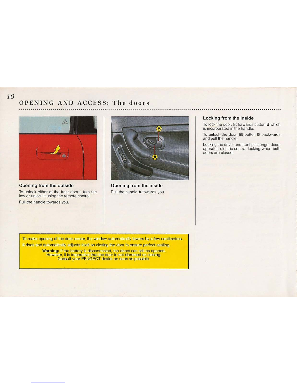
Opening from the outside
To unlock either of the front doors, turn the
key or unlock it using the remote control.
Pull the handle towards you.
Opening from the inside
Pull the handle A towards you.
To make opening of the door easier, the window automatically lowers by a few centimetres.
It rises and automatically adjusts itself on closing the door to ensure perfect sealing.
Warning: If the battery is disconnected, the doors can still be opened.
However, it is imperative that the door is not slammed on closing.
Consult your PEUGEOT dealer as soon as possible.
Locking from the inside
To lock the door, tilt forwards button B which
is incorporated in the handle.
To unlock the door, tilt button B backwards
and pull the handle.
Locking the driver and front passenger doors
operates electric central locking when both
doors are closed.

The boot
Locking or unlocking the boot at the
same time as the doors
Turn the key a quarter turn from A towards B
(the key returns to position A).
The boot locking is then controlled by the
remote control or the door locks.
The boot light is controlled by opening the
boot.
Locking or unlocking the boot inde-
pendently of the doors
These operations are only possible using the
main key. If you have to hand your vehicle to
a user to whom you do not wish to allow
access to the boot and the glove box, lock
them beforehand.
To lock the boot independently: lock the seat
backs (see page 75), turn the key a quarter
turn from A towards C (the key returns to
position A).
To revert to simultaneous operation with the
doors: turn the key to position B.
11
Before carrying out any work
which involves disconnection
of the battery, lower the
windows to permit opening
and closing of tile doors.
12
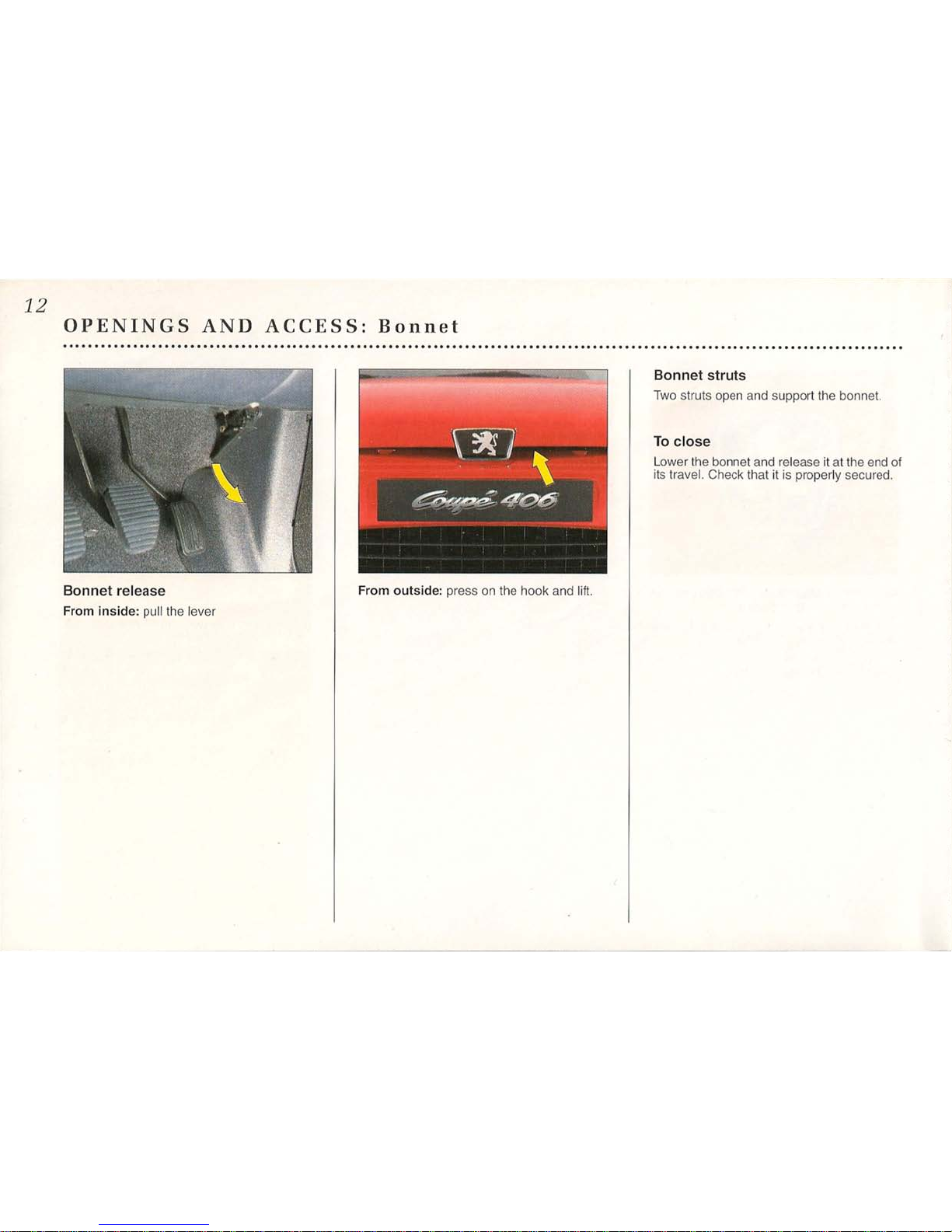
OPENINGS AND ACCESS: Bonnet
....................................................................................................................................
Bonnet release
From inside: pull the lever
Bonnet struts
Two struts open and support the bonnet.
To close
Lower the bonnet and release it at the end of
its travel. Check that it is properly secured.
From outside: press on the hook and lift.
Fuel filler flap and filling up with fuel
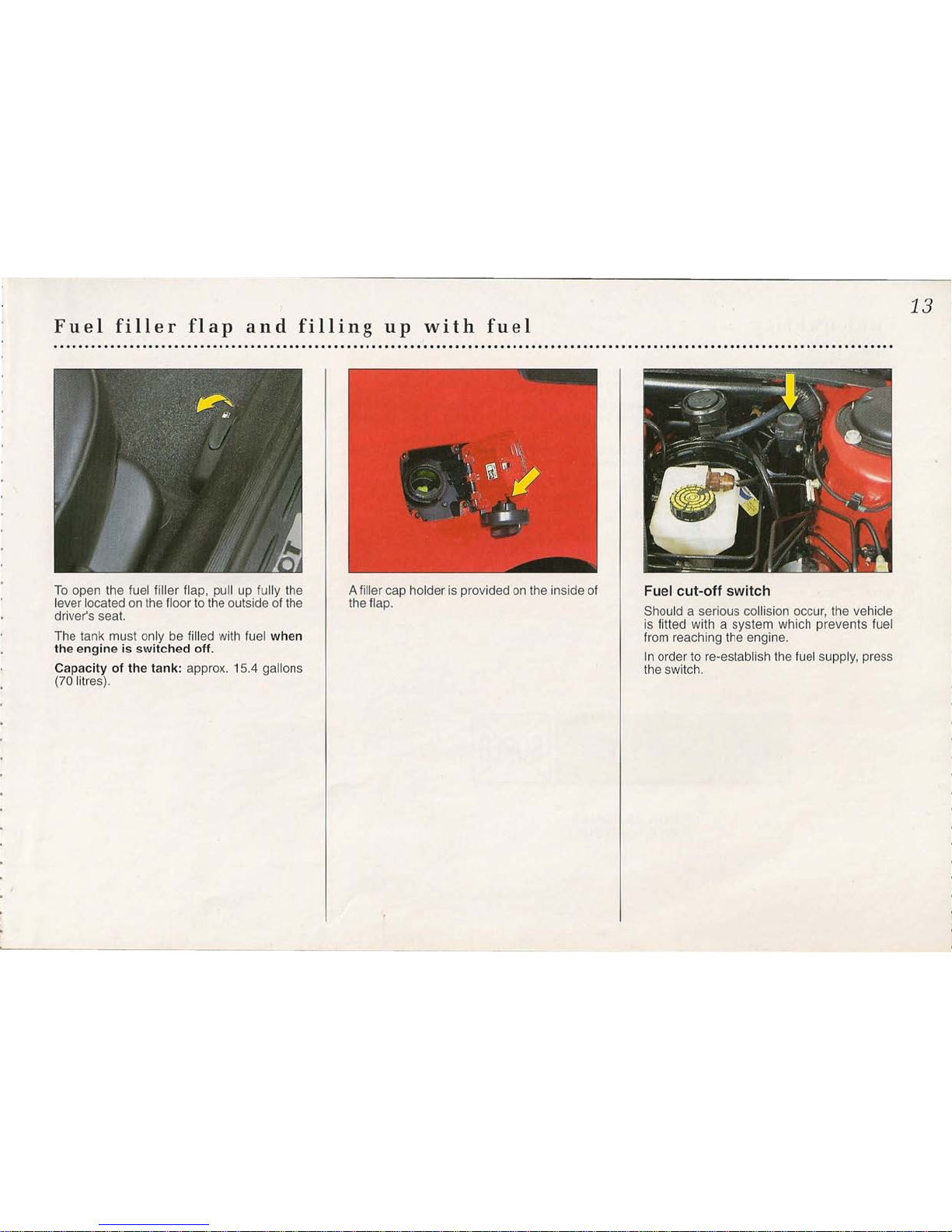
To open the fuel filler flap, pull up fully the
lever located on the floor to the outside of the
driver's seat.
The tank must only be filled with fuel when
the engine is switched off.
Capacity of the tank: approx. 15.4 gallons
(70 litres).
A filler cap holder is provided on the inside of
the flap.
13
Fuel cut-off switch
Should a serious collision occur, the vehicle
is fitted with a system which prevents fuel
from reaching the engine.
In order to re-establish the fuel supply, press
the switch.
14
Fuel quality
Automobiles PEUGEOT try to provide their engines not only with optimum performance coupled
with minimum consumption, but also to ensure long-term performance and driving pleasure.
The quality of the fuel used directly influences these factors. Manufacturers, inciudingAutomobiles
PEUGEOT, have recommended in a specification the characteristics which define the fuels best
suited to current engines.
The use of fuels conforming to the vehicle manufacturers' specification will therefore enable you
to appreciate better the dynamic qualities of your vehicle.
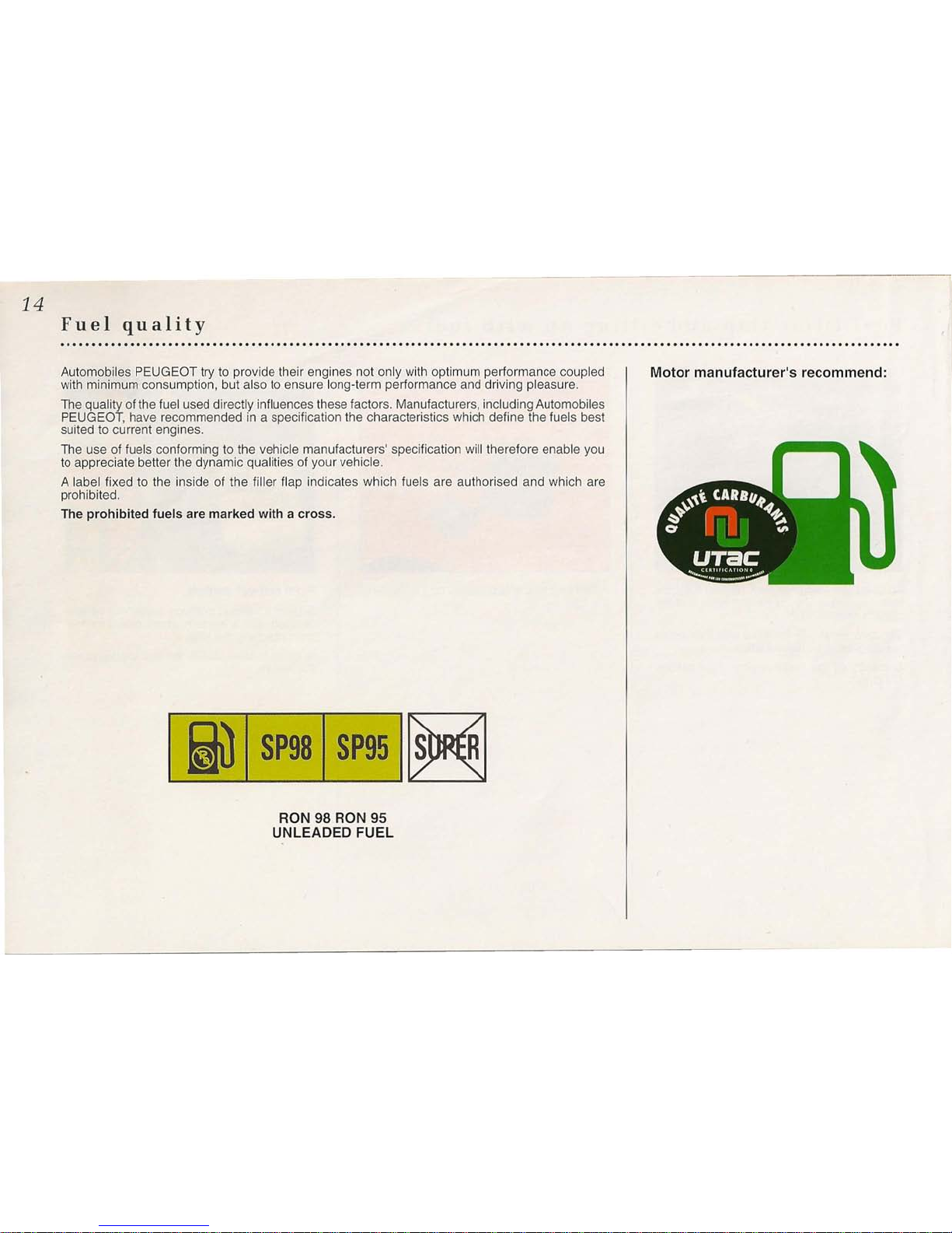
A label fixed to the inside of the filler flap indicates which fuels are authorised and which are
prohibited.
The prohibited fuels are marked with a cross.
I
fill
I SP9s1
SP951~
RON 98 RON
95
UNLEADED FUEL
Motor manufacturer's recommend:
The
catalytic converter
The catalytic converter is a delicate unit.
Pay attention to the instructions below.
Fuel:
- Only use unleaded fuel.
- Fill up as soon as the low fuel warning lamp comes on: driving with too Iowa fuel level can
cause the engine to misfire.
- Never put any additives into the engine oil: this can cause considerable damage to the catalytic
converter.
- Only use fuel additives recommended by the manufacturer.
Driving:
Starting from cold:
- Avoid successive cold starts where possible.
- Do not rev the engine.
While driving:
- Do not rev the engine just before switching off the ignition.
- Avoid parking or driving on easily inflammable materials such as dry leaves and/or dry grass ...
If you notice ...
- Starting difficulties, DO NOT PERSIST, consult your PEUGEOT dealer.
- Misfiring or a loss of power: reduce your speed and have your vehicle checked as quickly as
possible.
- Excessive noise: have the exhaust system checked.
15
I
A
I
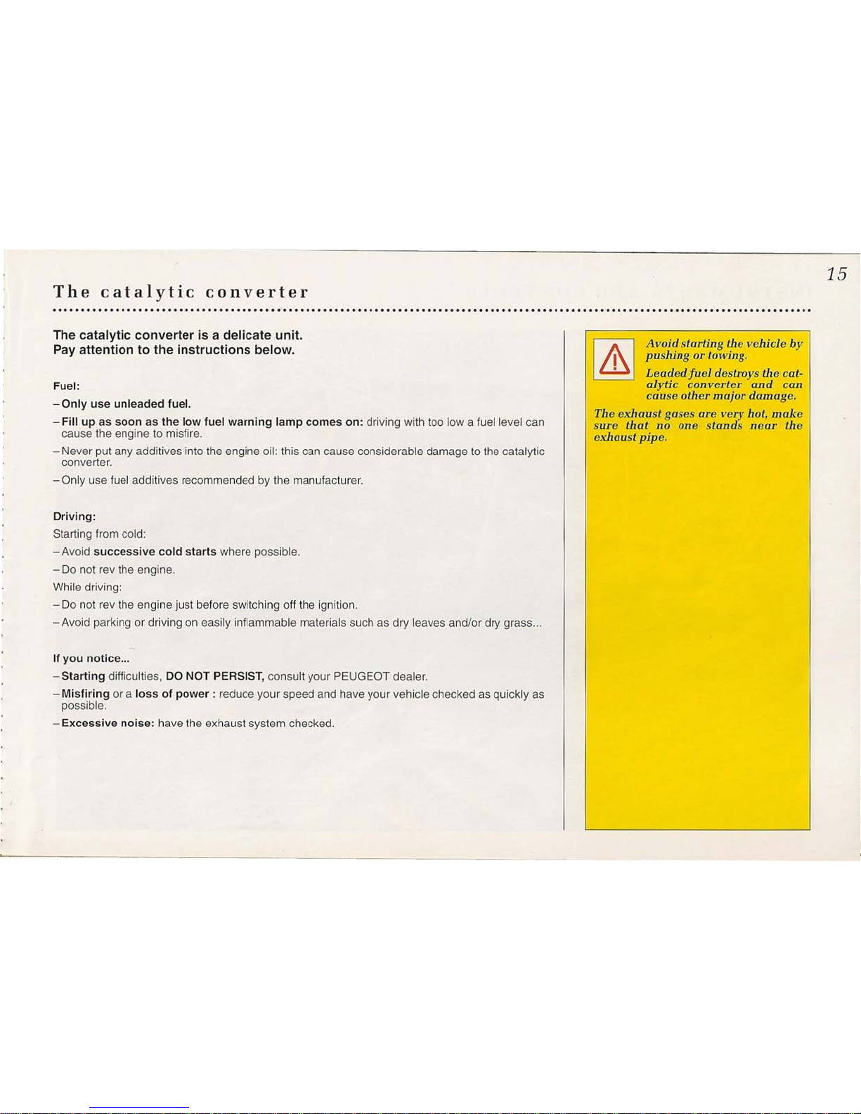
Avoj~ starting
0
e
vehicle by
I
pushmg or towing.
• Leadedfuel destroys the cat-
alytic converter and can
cause other major damage.
The exhaust gases are very hot, make
sure that no one stands near the
exhaust pipe.
16
INSTRUMENTS AND CONTROLS
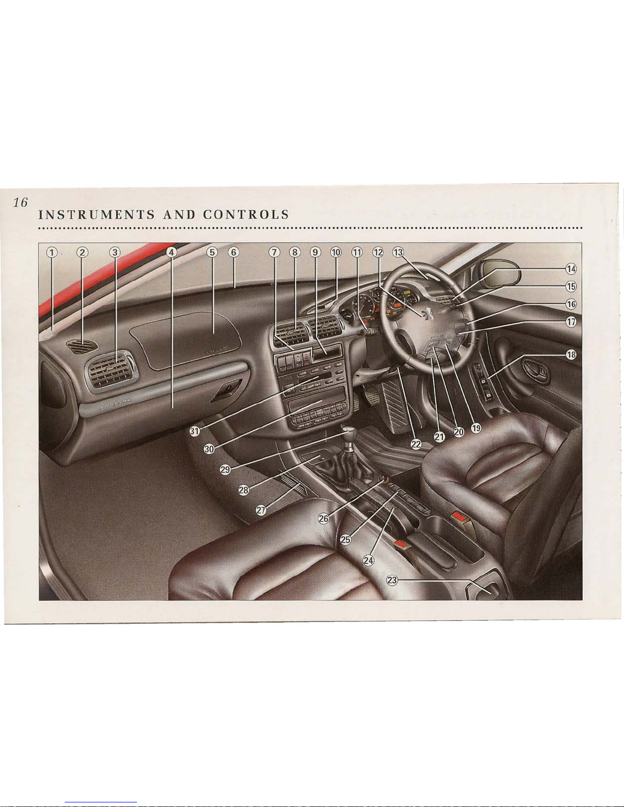
INSTRUMENTS AND CONTROLS*
1 - Left hand speaker location (tweeter).
2 - Left window demisting vent.
3 - Left hand directable side heating/venti-
lation vent and air flow control.
4 - Glove compartment.
5 - Passenger airbag.
6 - Windscreen demisting vents.
7 - Coded anti-start warning lamp.
Electronic suspension control.
Hazard warning lights control.
Heated rear screen control.
8 - Central directable heating/ventilation
vents and air flow control.
9 - Multi-function display.
10 - Digital clock.
11 - Lighting stalk, horn and direction indi-
cators.
Front and rear fog lights control'.
12 - Driver's airbag.
13 - Right hand speaker location (tweeter).
14 - Right hand directable side heating/ven-
tilation vent and flow control.
15 - Windscreen wash-wipe stalk.
16 - Radio control.
17 - Ignition switch.
18 -
Electric rear view mirror controls.
Window mechanism controls.
19 -
Cruise control switch.
Alarm switch.
20 -
Headlight height adjustment.
17
21 - Fusebox and coded anti-start keypad.
22 - Steering wheel adjustment control.
23 -
Rear ashtray.
24 -
Handbrake.
25 - Left hand heated seat control.
Right hand heated seat control.
26 - Lighter.
27 -
Rear passenger footwell heating vent.
28 - Front ashtray.
29 -
Gear lever.
30 -
Radio location.
31 - Air conditioning controls.
, According to specification
18
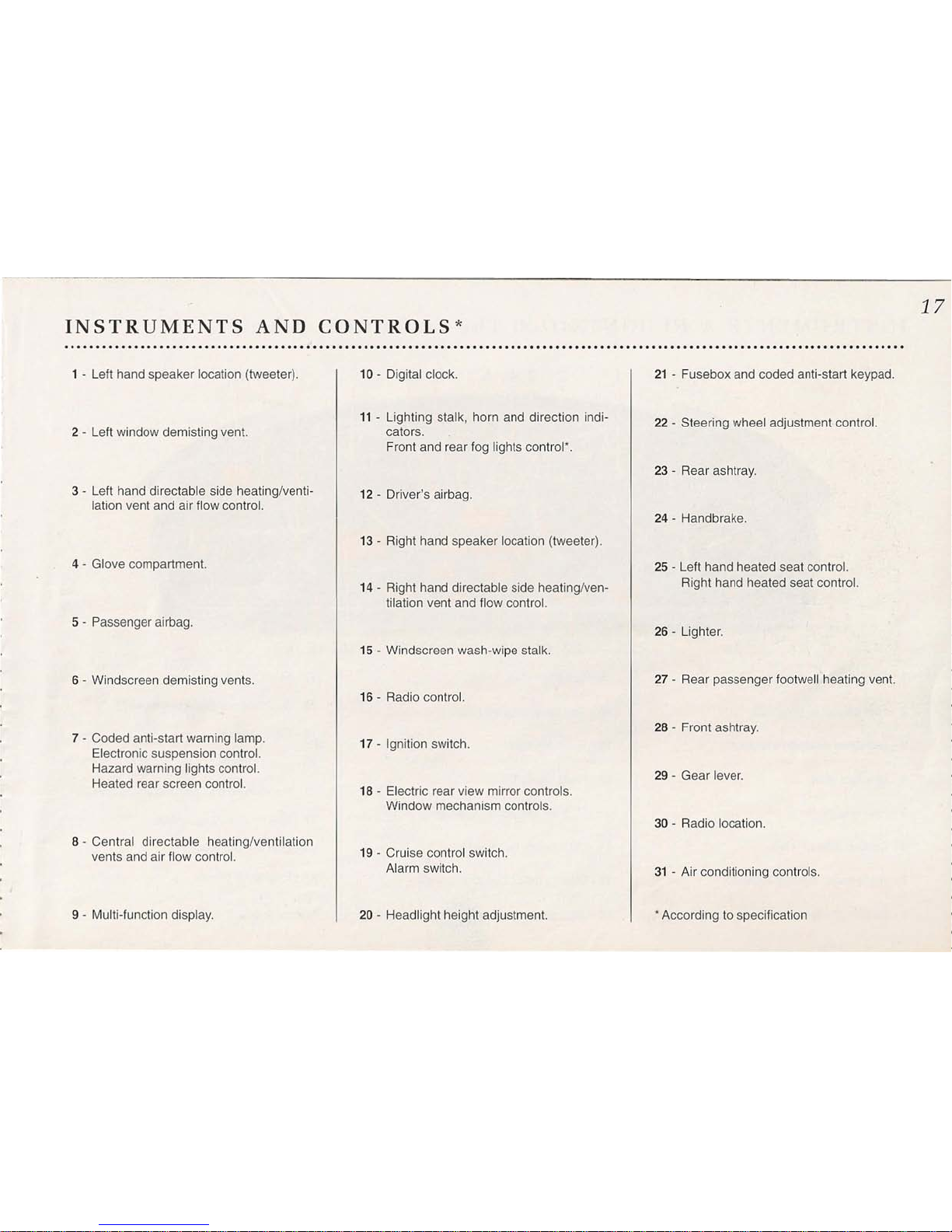
INSTRUMENTS AND CONTROLS: The instrument p a n e l "
....................................................................................................................................
1
2345678
9
10 11 12
24
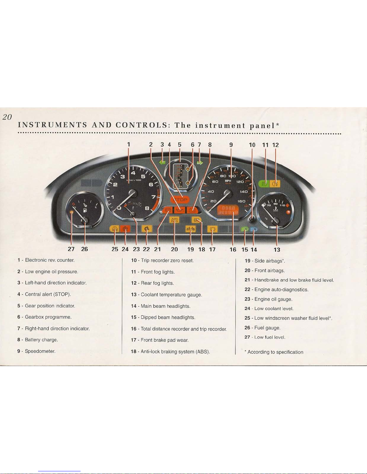
1 - Electronic rev. counter.
2 - Low engine oil pressure.
3 - Left-hand direction indicator.
4 - Low fuel level.
5 - Fuel gauge.
6 - Central alert (STOP).
7 - Right-hand direction indicator.
8 - Battery charge.
23
22 21
20
19 18 17
16 15
14
13
9 - Speedometer.
10 - Trip recorder zero reset.
11 - Front fog lights.
12 - Rear fog lights.
13 - Coolant temperature gauge.
14 - Main beam headlights.
15 - Dipped beam headlights.
16 - Total distance recorder and trip recorder.
17 - Front brake pad wear.
18 - Anti-lock braking system (ABS).
19 - Side airbags*.
20 - Front airbags.
21 - Handbrake and low brake fluid level.
22 - Engine auto-diagnostics.
23 - Low coolant level.
24 - Engine oil gauge.
* According to specification
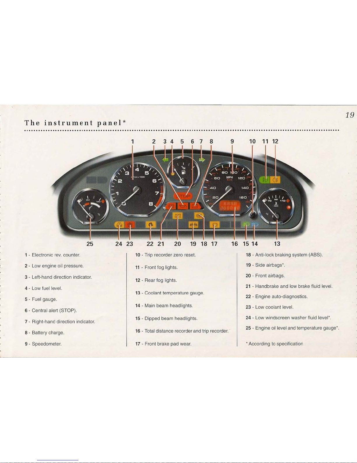
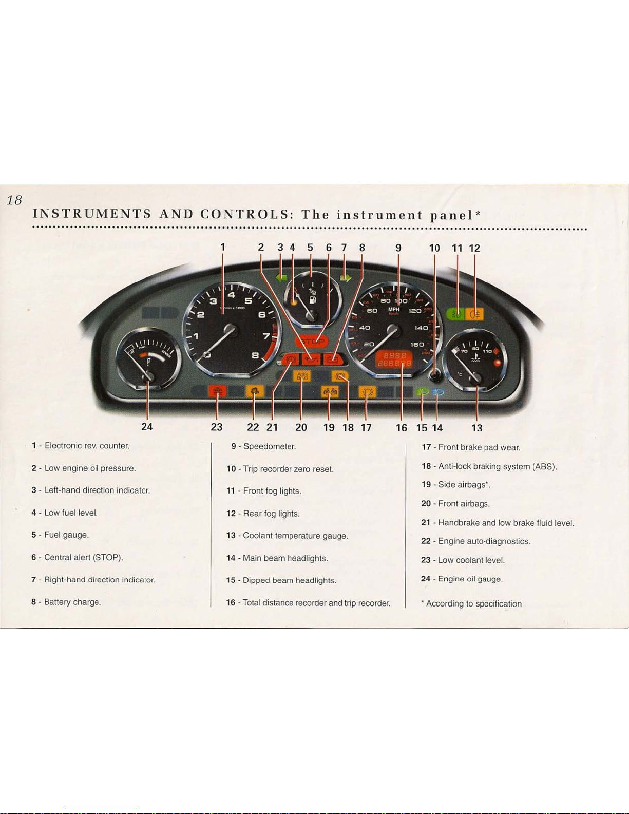
The instrument panel*
1
2345678
19
9
10 11 12
25 24 23
1 - Electronic rev. counter.
2 - Low engine oil pressure.
3 - Left-hand direction indicator.
4 - Low fuel level.
5 - Fuel gauge.
6 - Central alert (STOP).
7 - Right-hand direction indicator.
8 - Battery charge.
9 - Speedometer.
22 21
20
19 18 17
10 - Trip recorder zero reset.
11 - Front fog lights.
12 - Rear fog lights.
13 - Coolant temperature gauge.
14 - Main beam headlights.
15 - Dipped beam headlights.
16 - Total distance recorder and trip recorder.
17 - Front brake pad wear.
16 15 14 13
18 - Anti-lock braking system (ABS).
19 - Side airbags*.
20 - Front airbags.
21 - Handbrake and low brake fluid level.
22 - Engine auto-diagnostics.
23 - Low coolant level.
24 - Low windscreen washer fluid level'.
25 - Engine oil level and temperature gauge'.
, According to specification
20
INSTRUMENTS AND CONTROLS: The instrument panel
*
....................................................................................................................................
1
2 3 4 5
678
9 10 11 12
27 26
25 24 23 22 21
10 - Trip recorder zero reset.
. 1 - Electronic rev. counter.
2 - Low engine oil pressure.
3 - Left-hand direction indicator.
4 - Central alert (STOP).
5 - Gear position indicator.
6 - Gearbox programme.
7 - Right-hand direction indicator.
8 - Battery charge.
9 - Speedometer.
20 19 18 17
16 15 14
13
11 - Front fog lights.
12 - Rear fog lights.
13 - Coolant temperature gauge.
14 - Main beam headlights.
15 - Dipped beam headlights.
16 - Total distance recorder and trip recorder.
17 - Front brake pad wear.
18 - Anti-lock braking system (ABS).
19 - Side airbags*.
20 - Front airbags.
21 - Handbrake and low brake fluid level.
22 - Engine auto-diagnostics.
23 - Engine oil gauge.
24 - Low coolant level.
25 - Low windscreen washer fluid level*.
26 - Fuel gauge.
27 - Low fuel level.
* According to specification
INSTRUMENTS AND CONTROLS: Warning lights
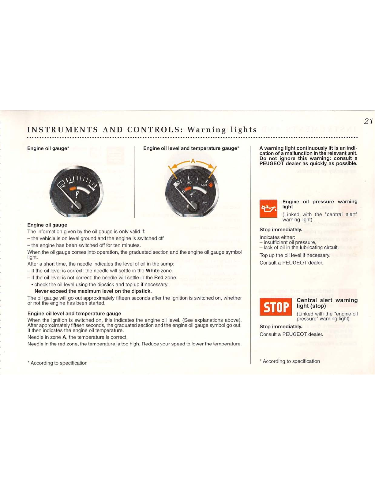
Engine oil gauge* Engine oil level and temperature gauge*
Engine oil gauge
The information given by the oil gauge is only valid if:
- the vehicle is on level ground and the engine is switched off
- the engine has been switched off for ten minutes.
When the oil gauge comes into operation, the graduated section and the engine oil gauge symbol
light.
After a short time, the needle indicates the level of oil in the sump:
- If the oil level is correct: the needle will settle in the White zone.
- If the oil level is not correct: the needle will settle in the Red zone:
• check the oil level using the dipstick and top up if necessary.
Never exceed the maximum level on the dipstick.
The oil gauge will go out approximately fifteen seconds after the ignition is switched on, whether
or not the engine has been started.
Engine oil level and temperature gauge
When the ignition is switched on, this indicates the engine oil level. (See explanations above).
After approximately fifteen seconds, the graduated section and the engine oil gauge symbol go out.
It then indicates the engine oil temperature.
Needle in zone A, the temperature is correct.
Needle in the red zone, the temperature is too high. Reduce your speed to lower the temperature.
• According to specification
21
A warning light continuously lit is an indi-
cation of a malfunction in the relevant unit.
Do not ignore this warning: consult a
PEUGEOT dealer as quickly as possible.
rI
Engine oil pressure warning
'--.; light
(Linked with the "central alert"
warning light).
Stop immediately.
Indicates either:
- insufficient oil pressure,
- lack of oil in the lubricating circuit.
Top up the oil level if necessary.
Consult a PEUGEOT dealer.
Em
Central alert warning
I'
light (stop)
(Linked with the "engine oil
pressure" warning light).
Stop immediately.
Consult a PEUGEOT dealer.
• According to specification
22
INSTRUMENTS AND CONTROLS: Warning lights
*
....................................................................................................................................
A warning light continuously lit is an
indication of amalfunction in the rel-
evant unit. Do not ignore this
warning: consult a PEUGEOT dealer
as quickly as possible.
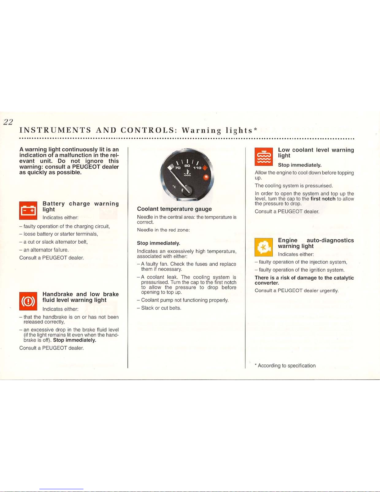
re
Battery charge warning
_ light
Indicates either:
- faulty operation of the charging circuit,
- loose battery or starter terminals,
- a cut or slack alternator belt,
- an alternator failure.
Consult a PEUGEOT dealer.
m
Handbrake and low brake
o
fluid level warning light
Indicates either:
- that the handbrake is on or has not been
released correctly,
- an excessive drop in the brake fluid level
(if the light remains lit even when the hand-
brake is off). Stop immediately.
Consult a PEUGEOT dealer.
Coolant temperature gauge
Needle in the central area: the temperature is
correct.
Needle in the red zone:
Stop immediately.
Indicates an excessively high temperature,
associated with either:
- A faulty fan. Check the fuses and replace
them if necessary.
- A coolant leak. The cooling system is
pressurised. Turn the cap to the first notch
to allow the pressure to drop before
opening to top up.
- Coolant pump not functioning properly.
- Slack or cut belts.
liD
Low coolant level warning
-- light
Stop immediately.
Allow the engine to cool down before topping
up.
The cooling system is pressurised.
In order to open the system and top up the
level, turn the cap to the first notch to allow
the pressure to drop.
Consult a PEUGEOT dealer.
Engine auto-diagnostics
-K
warning light
Indicates either:
- faulty operation of the injection system,
- faulty operation of the ignition system.
There is a risk of damage to the catalytic
converter.
Consult a PEUGEOT dealer urgently.
*
According to specification
23
INSTRUMENTS AND CONTROLS: Warning lights*
..................................................................................................................................................................
......
'
.
A warning light continuously lit is an indi-
cation of a malfunction in the relevant unit.
Do not ignore this warning: consult
a
PEUGEOT dealer as quickly as possible.
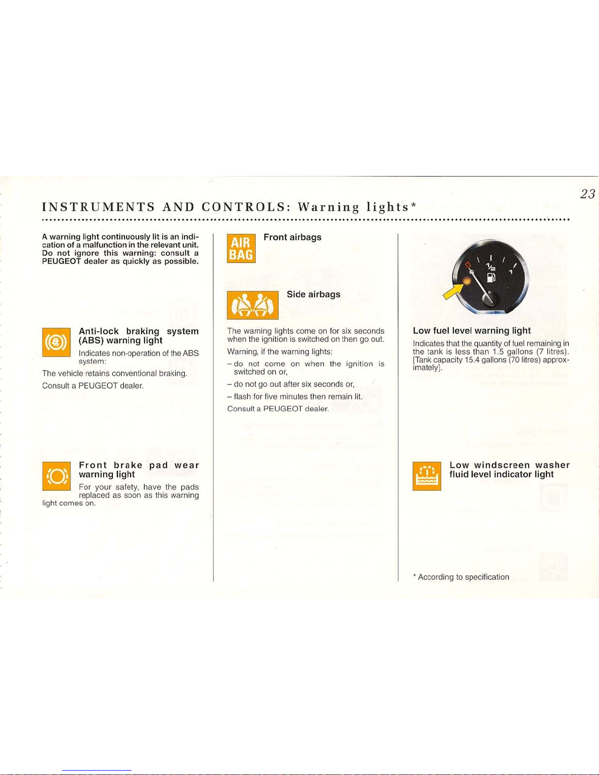
~
Anti-lock braking system
o
(ASS) warning light
Indicates non-operation of the ABS
system:
The vehicle retains conventional braking.
Co~uHaPEUGEOTdea~~
Front brake pad wear
• warning light
For your safety, have the pads
replaced as soon as this warning
light comes on.
j •
Front airbags
: I
Side airbags
The warning lights come on for six seconds
when the ignition is switched on then go out.
Warning, if the warning lights:
- do not come on when the ignition is
switched on or,
- do not go out after six seconds or,
- flash for five minutes then remain lit.
Consult a PEUGEOT dealer.
\ I ,.
r._\ ~ "
.~
.
Low fuel level warning light
Indicates that the quantity of fuel remaining in
the tank is less than 1.5 gallons (7 litres).
[Tank capacity 15.4 gallons (70 litres) approx-
imately).
Low windscreen washer
fluid level indicator light
*
According to specification

24
INSTRUMENTS AND CONTROLS: Signalling
The steering wheel stalk permits opera-
tion of the lighting, the front and rear fog
lights, the headlamp flash, the direction
indicators and the horn.
Front lights
Selection is by turning ring A.
All lights off
[11]
Turn the ring one notch forwards
Side lights
B
Turn the ';09
0"'
notch forwards,
~ Dipped beam/main
~beam
Dipped, beam/main beam change
Pull the stalk towards you until it clicks to
change between dipped and main beam.
Lights-on buzzer
Operates on opening a door, with the ignition
off, to indicate that the lights are still on. Stops
on closing the doors, on switching off the
lights or on switching on the ignition.
Adjusting the headlamps
Depending on the load carried, see page 102.
Front and rear fog lights
To switch on, turn ring B. The position is con-
firmed by the warning lights on the fascia.
[11]
Lights off
Em
Front fog lights lit
These operate with the side lights and the
main/dipped beam headlights.
lE
Front and rear fog
•• lights lit
These operate with the side
lights and the dipped/main
beam headlights. Switching off the side lights
switches off the rear fog light and reverts to
the front fog lights position.
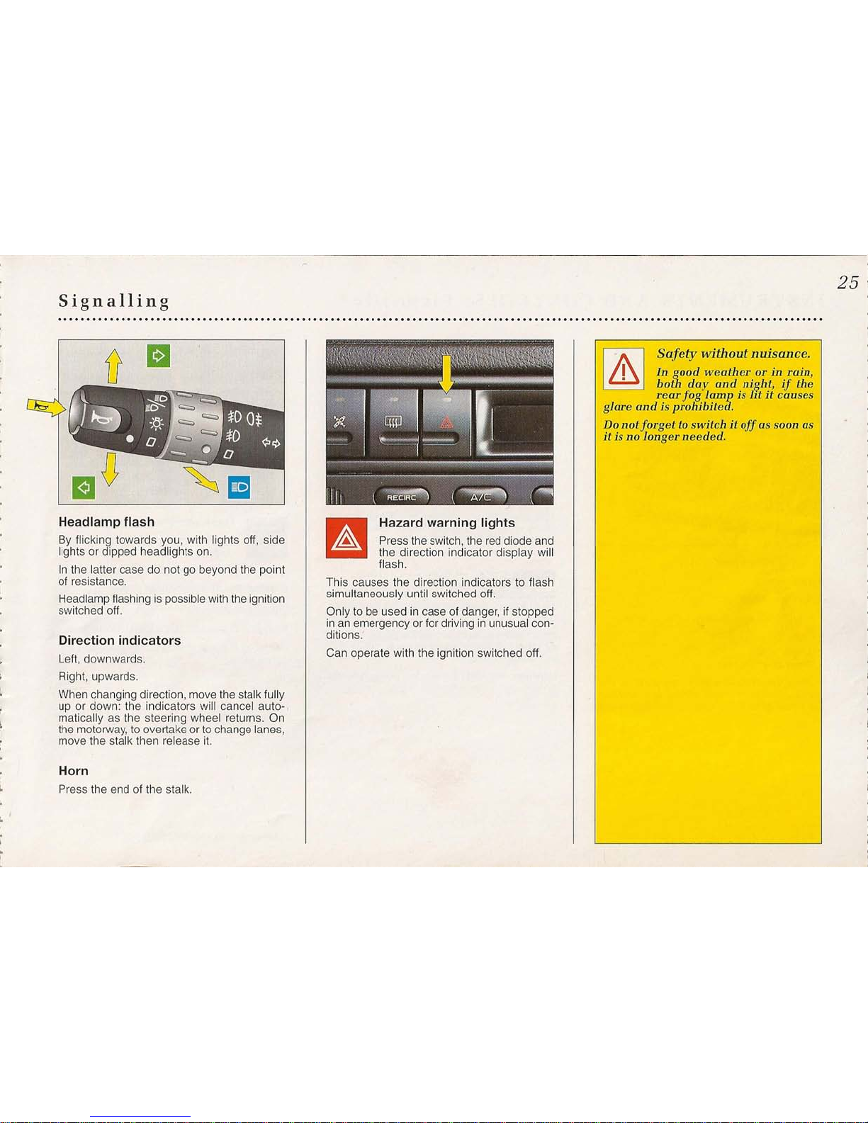
Signalling
Headlamp flash
By flicking towards you, with lights off, side
lights or dipped headlights on.
In the latter case do not go beyond the point
of resistance.
Headlamp flashing is possible with the ignition
switched off.
Direction indicators
Left, downwards.
Right, upwards.
When changing direction, move the stalk fully
up or down: the indicators will cancel auto-,
matically as the steering wheel returns. On
the motorway, to overtake or to change lanes,
move the stalk then release it.
Horn
Press the end of the stalk.
Hazard warning lights
Press the switch, the red diode and
the direction indicator display will
flash.
This causes the direction indicators to flash
simultaneously until switched off.
Only to be used in case of danger, if stopped
in an emergency or for driving in unusual con-
ditions.
Can operate with the ignition switched off.
25
I
&
I
Safety without nuisance.
I
In qood weather or in rain,
• both day and night, if the
rear fog lamp is lit it causes
glare and is prohibited.
Do
notforget to switch it of!assoon
as
it isnolonger needed.
26
INSTRUMENTS AND CONTROLS: Visibility*
....................................................................................................................................
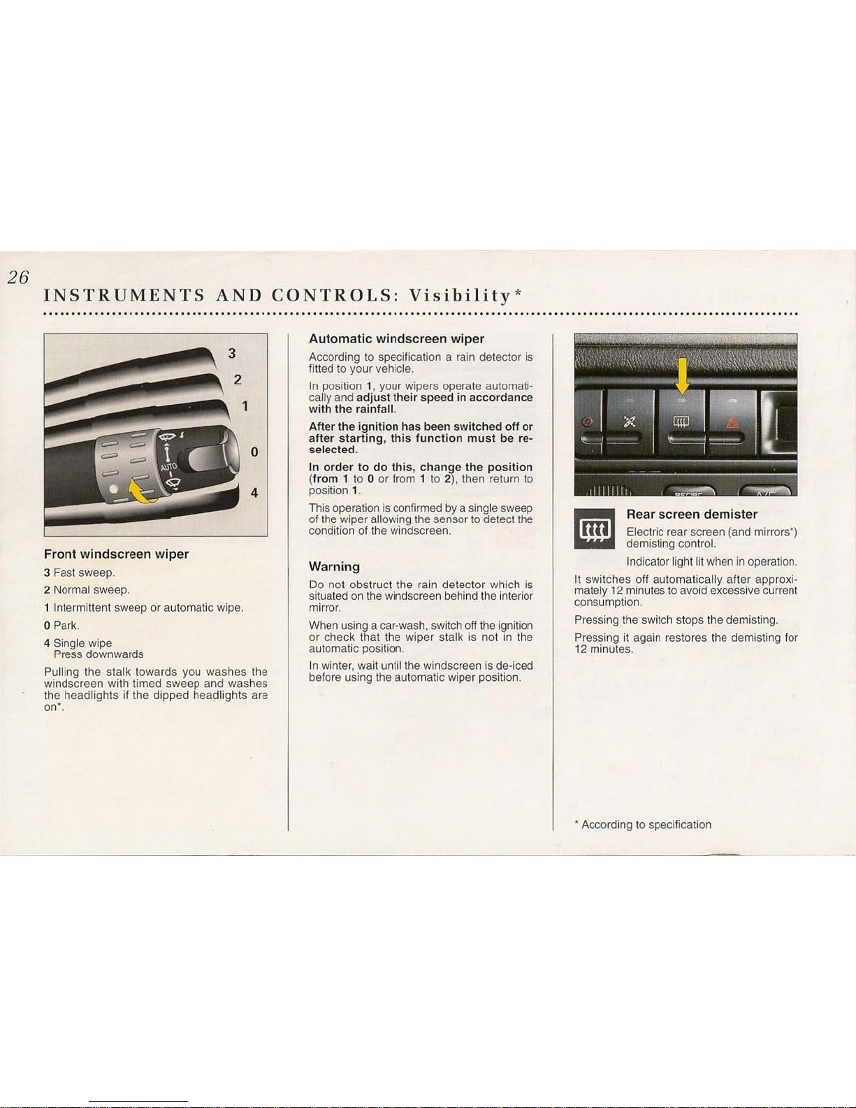
Front windscreen wiper
3
Fast sweep.
2 Normal sweep.
1
Intermittent sweep or automatic wipe.
o
Park.
4 Single wipe
Press downwards
Pulling the stalk towards you washes the
windscreen with timed sweep and washes
the headlights if the dipped headlights are
on>.
o
Automatic windscreen wiper
According to specification a rain detector is
fitted to your vehicle.
In position 1, your wipers operate automati-
cally and adjust their speed in accordance
with the rainfall.
After the ignition has been switched off or
after starting, this function must be re-
selected.
In order to do this, change the position
(from1to0or from1to
2),
then return to
position
1.
This operation is confirmed by a single sweep
of the wiper allowing the sensor to detect the
condition of the windscreen.
Warning
Do not obstruct the rain detector which is
situated on the windscreen behind the interior
mirror.
When using a car-wash, switch off the ignition
or check that the wiper stalk is not in the
automatic position.
In winter, wait until the windscreen is de-iced
before using the automatic wiper position.
4
Rear screen demister
Electric rear screen (and mirrors»
demisting control.
Indicator light lit when in operation.
It switches off automatically after approxi-
mately12minutes to avoid excessive current
consumption.
Pressing the switch stops the demisting.
Pressing it again restores the demisting for
12
minutes.
>
According to specification
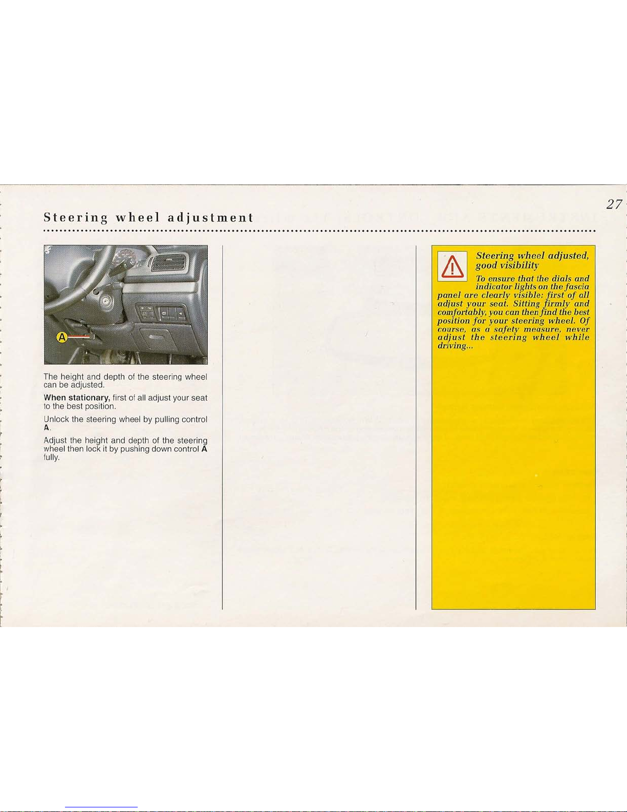
Steering wheel adjustment
The height and depth of the steering wheel
can be adjusted.
When stationary, first of all adjust your seat
to the best position.
Unlock the steering wheel by pulling control
A.
Adjust the height and depth of the steering
wheel then lock it by pushing down control A
fully.
27
I
11\
I
Steering wheel adjusted,
I
good visibility
• To ensure that the dials and
indicator lights
OIl
the fascia
panel are clearly visible~. irst of all
adjust your seat. Sitting irmly and
comfortably, you call then 'ind the best
position for your steering wheel. Of
course,
as a
safety measure, never
adjust the steering wheel while
driving ...
28
INSTRUMENTS AND CONTROLS: The mirrors
m\
. '
•• _ , ~ Co»
, ~, ,- ,I .•/"
.
\
..
\,;
~
..•.•.•.
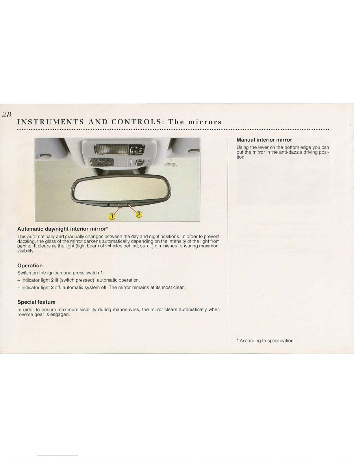
Automatic day/night interior mirror*
This automatically and gradually changes between the day and night positions. In order to prevent
dazzling, the glass of the mirror darkens automatically depending on the intensity of the light from
behind. It clears as the light (light beam of vehicles behind, sun ...) diminishes, ensuring maximum
. visibility.
Operation
Switch on the ignition and press switch 1:
- Indicator light 2 lit (switch pressed): automatic operation.
- Indicator light 2 off: automatic system off. The mirror remains at its most clear.
Special feature
In order to ensure maximum visibility during manoeuvres, the mirror clears automatically when
reverse
gear is engaged.
Manual interior mirror
Using the
lever
on the bottom edge you can
put the mirror in the anti-dazzle driving posi-
tion.
* According to specification
-----------------------------------------------------------------------------------------------------
The mirrors
29
....................................................................................................................................
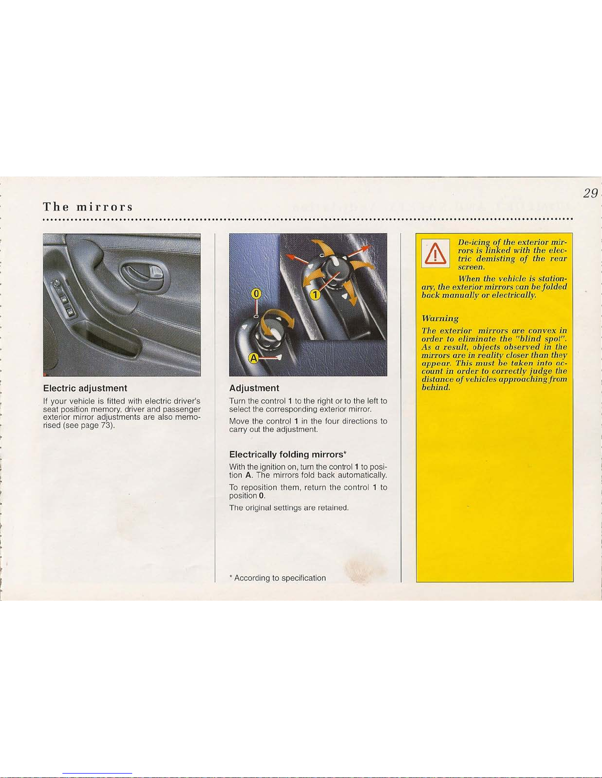
Electric adjustment
If your vehicle is fitted with electric driver's
seat position memory, driver and passenger
exterior mirror adjustments are also memo-
rised (see page 73).
Adjustment
Turn the control 1 to the right or to the left to
select the corresponding exterior mirror.
Move the control 1 in the four directions to
carry out the adjustment.
Electrically folding mirrors*
With the ignition on, turn the control 1 to posi-
tion A. The mirrors fold back automatically.
To reposition them, return the control 1 to
position O.
The original settings are retained.
*
According to specification
Warning
The exterior mirrors are convex in
order to eliminate the "blind spot".
Asaresult, objects observed in the
mirrors
are in reality closer than tlley
appeal'. This
must
be taken into ac-
countinorder to correctly judge the
distance of vehicles approaching from
behind.
I
A
I
De-icingofthe
exterior
mir-
I
rors is linked with the elec-
• tric demisting of the rear
screen.
When the vehicle is station-
my,
the exterior mirrors can be folded
back manuallyorelectrically.
 Loading...