

Page 1
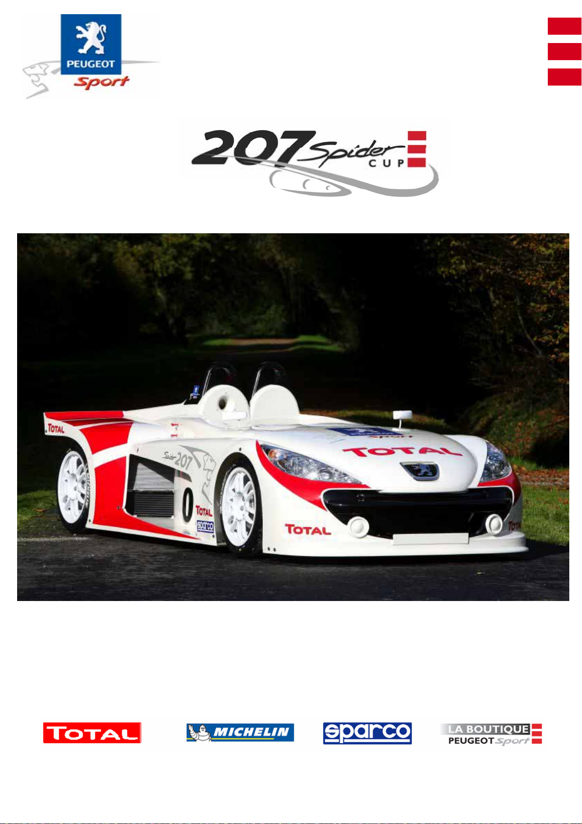
TECHNICAL INSTRUCTIONS
Page 2
Ce document est la propriété de Peugeot Sport et ne peut être reproduit ou communiqué sans autorisation.
This document is the property of Peugeot Sport and may not be copied o r circulated without permission .
TECHNICAL INSTRUCTIONS
TECHNICAL INSTRUCTIONS
Pages
2019181716151413121110987654321
D
O
N
D
O
N
01010101010101
E
I
T
I
S
Pages
E
I
T
I
S
01010101010101010101010101
4039383736353433323130292827262524232221
0101010101010101010101010101010101010101
StudyVer.
Date
OCM
W.Briand01StudyVer.
14/03/2007Date
?OCM
207 Spider Technical Instructions
NOT 207 SPI-80
1
Page 3
Ce document est la propriété de Peugeot Sport et ne peut être reproduit ou communiqué sans autorisation.
This document is the property of Peugeot Sport and may not be copied o r circulated without permission .
Pages
6059585756555453525150494847464544434241
D
O
N
D
O
N
0101
010101010101010101010101010101010101
E
I
T
I
S
Pages
7776757473727170696867666564636261
0101010101010101010101010101010101
E
I
T
I
S
01Ed. :
207 Spider Technical Instructions
NOT 207 SPI-80
2
Page 4

Ce document est la propriété de Peugeot Sport et ne peut être reproduit ou communiqué sans autorisation.
This document is the property of Peugeot Sport and may not be copied o r circulated without permission .
Table of contents
General points page 4
Equipment page 13
Body page 17
Electrical page 24
Engine page 43
Gearbox page 50
Running gear page 58
Steering page 66
Brakes page 68
Roadholding page 74
01Ed. :
207 Spider Technical Instructions
NOT 207 SPI-80
3
Page 5
Ce document est la propriété de Peugeot Sport et ne peut être reproduit ou communiqué sans autorisation.
This document is the property of Peugeot Sport and may not be copied o r circulated without permission .
General points
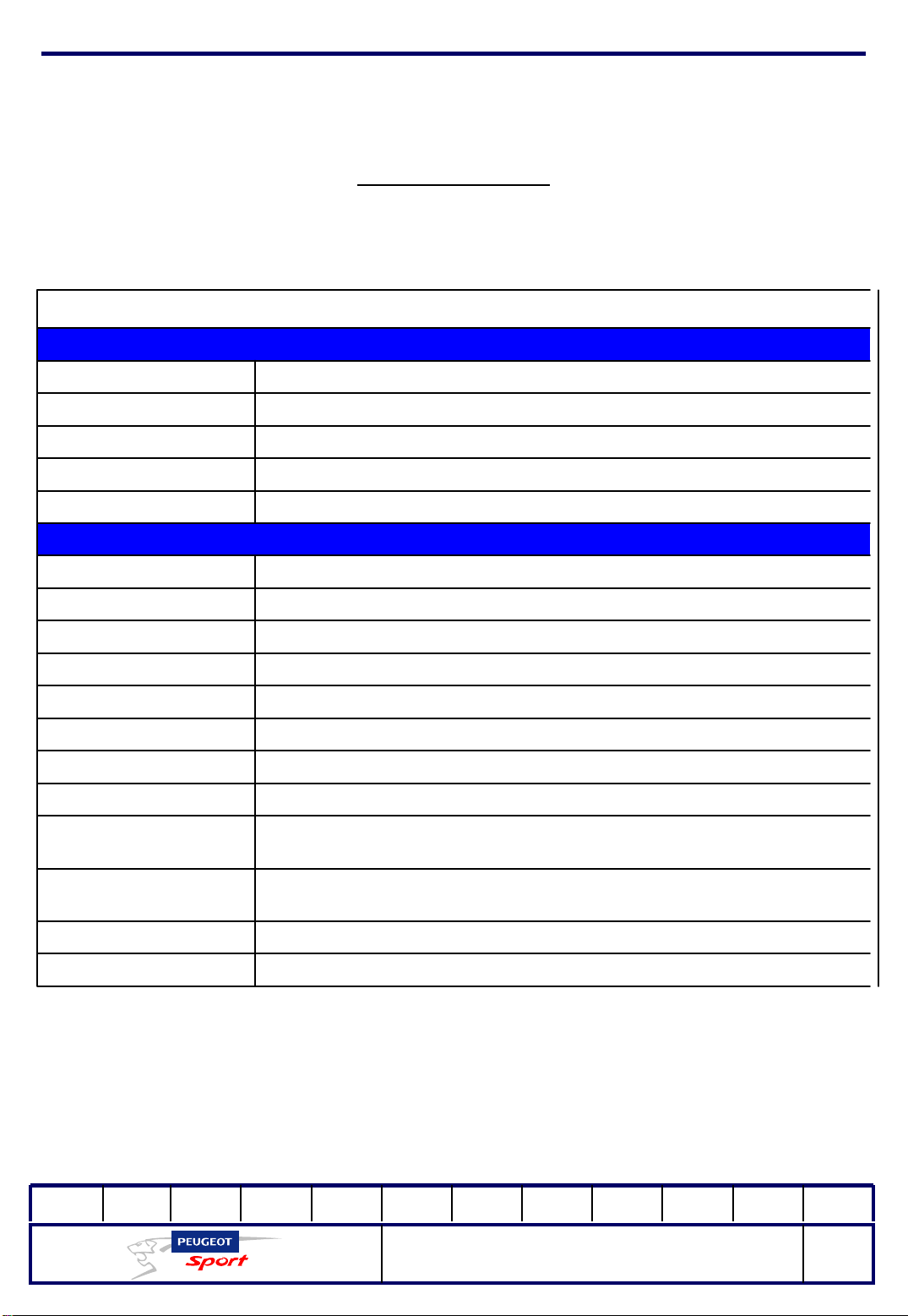
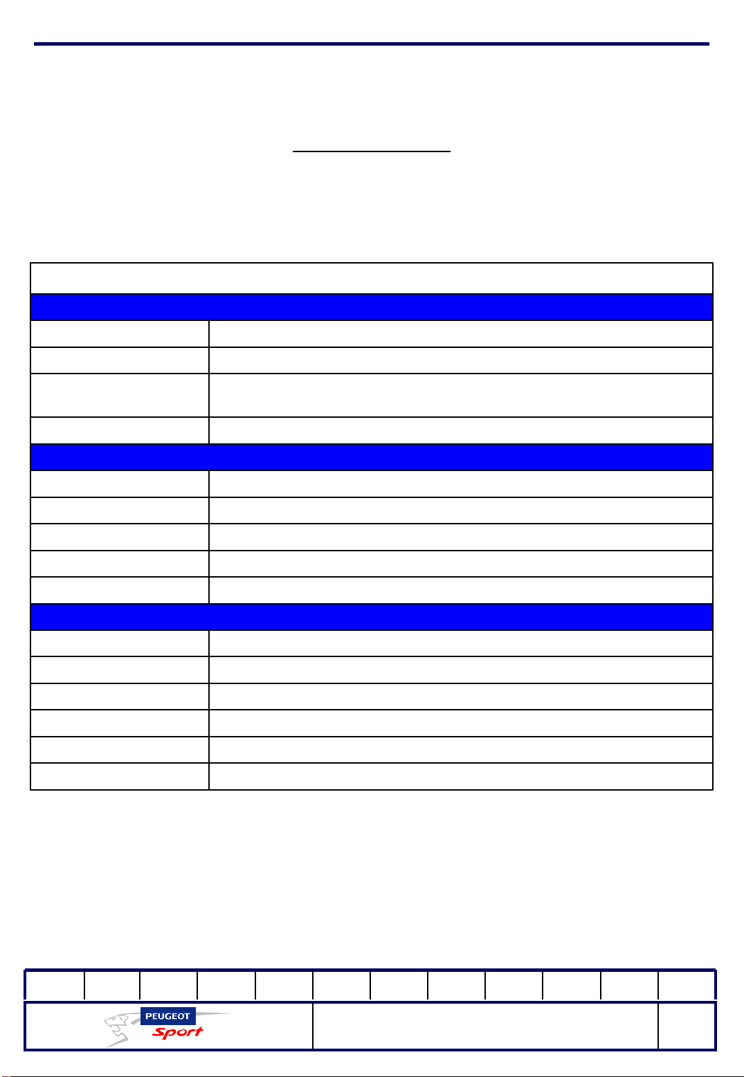
207 SPIDER TECHNICAL SPECIFICATIONS
CHASSIS
Two-seater, bucket seats Type
Structure
Type of turbo
injection/control
Three-part tubular chassis
Double-wishboneFront and rear axle
Combined spring-shock absorber unit with adjustable rocker arms and tie rods Front/rear shock absorber
Front and rearAnti-roll bars
ENGINE
EP6DTS Central rear transverse positionType/Positioning
Twin scroll, fixed-geometry
1598 cm3CC:
128kWPower
240 N.mMax torque
6,500rpmMax engine speed
4No. of cylinders
16No. of valves
Chain-driven/2 ACC (variable intake timing device/hydraulic tappetsTiming
Direct injection/BOSCH MED 17.4Type of
(front cradle, cockpit chassis, rear cradle)
Wet sump with anti-buoyancy metal panelLubrication
WaterCooling
01Ed. :
207 Spider Technical Instructions
NOT 207 SPI-80
4
Page 6
wheel rims
Ce document est la propriété de Peugeot Sport et ne peut être reproduit ou communiqué sans autorisation.
This document is the property of Peugeot Sport and may not be copied o r circulated without permission .
General points
207 SPIDER TECHNICAL SPECIFICATIONS
STEERING/BRAKES
Assisted steering rack as standardSteering
Ventilated disk Ø 283mm/26 mm thick/single-piston calliperFront and rear brakes
8J x 18''Single-unit, aluminium
Overall length/Overall
width
Front/rear axle
assembly
Minimum unladen weight
MICHELIN 21/65-18: slick S8B - rain P2C Front/rear tyres
TRANSMISSION
Two drive wheels/rear wheel driveTransmission
Sadev ST75-14 + Mar 6-speed, dog clutch Gearbox
Sequential using steering-wheel mounted paddlesGear changes
Self-locking, three-disk, 45°/80°slopesDifferential
Standard mechanism and single fritted diskClutch
DIMENSIONS / WEIGHT / CAPACITY
4,131 mm/1,854 mm
953 mm/578 mm Front/rear overhang
1,505 mm/1,615 mm
2,600 mmWheelbase
720 kg
60-litre petrolTank capacity
01Ed. :
207 Spider Technical Instructions
NOT 207 SPI-80
5
Page 7
Ce document est la propriété de Peugeot Sport et ne peut être reproduit ou communiqué sans autorisation.
This document is the property of Peugeot Sport and may not be copied o r circulated without permission .
General points
The left-hand drive 207 Spider meets the requirements of FIA regulations.
It is sold by the Peugeot Sport Boutique and intended exclusively for use on
competitive racing circuits.
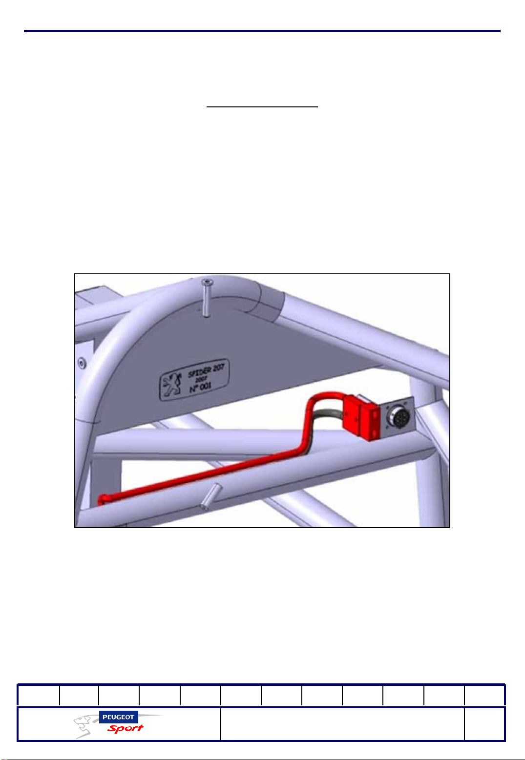
The Peugeot plate is compulsory on the 207 Spider and is welded onto the
cockpit chassis directly opposite the multifunction screen.
The example above illustrates the manufacturer's plate on 207 Spider with:
- the name of the car
- the year of manufacture
- chassis number
01Ed. :
207 Spider Technical Instructions
NOT 207 SPI-80
6
Page 8
Ce document est la propriété de Peugeot Sport et ne peut être reproduit ou communiqué sans autorisation.
This document is the property of Peugeot Sport and may not be copied o r circulated without permission .
General points
In addition to the manufacturer's plate, the serial numbers given below must be
legible on a permanent basis:
- engine serial number
- gearbox serial number
- engine ECU serial number
- gearbox ECU serial number
- data logger serial number
Worn or damaged parts must be replaced with Genuine PEUGEOT or PEUGEOT
SPORT parts, referenced by AUTOMOBILES PEUGEOT or PEUGEOT SPORT (see the
207 Spider Spare Parts catalogue.
The methods specified by AUTOMOBILES PEUGEOT or PEUGEOT SPORT as well as
the technical regulations must be followed for all work or repairs carried out on
the car.
The car must be presented for each race in meticulous
condition and meeting the requirements in terms of
mechanics, body and identification.
01Ed. :
207 Spider Technical Instructions
NOT 207 SPI-80
7
Page 9
Ce document est la propriété de Peugeot Sport et ne peut être reproduit ou communiqué sans autorisation.
This document is the property of Peugeot Sport and may not be copied o r circulated without permission .
General points
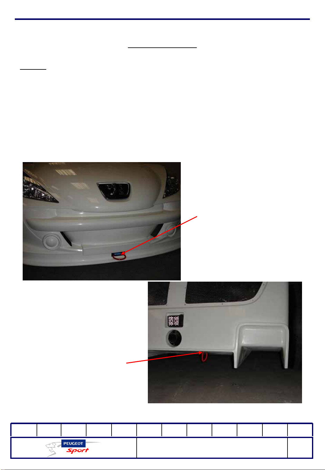
Towing:
207 Spider has two towing rings:
- in the front, fixed to the chassis with a strap.
- at the rear, located under the diffuser (on the right).
These rings must be identified with stickers approved by the FIA and must be
legible at all times.
Rear ring
Front ring
01Ed. :
207 Spider Technical Instructions
NOT 207 SPI-80
8
Page 10
Ce document est la propriété de Peugeot Sport et ne peut être reproduit ou communiqué sans autorisation.
This document is the property of Peugeot Sport and may not be copied o r circulated without permission .
General points
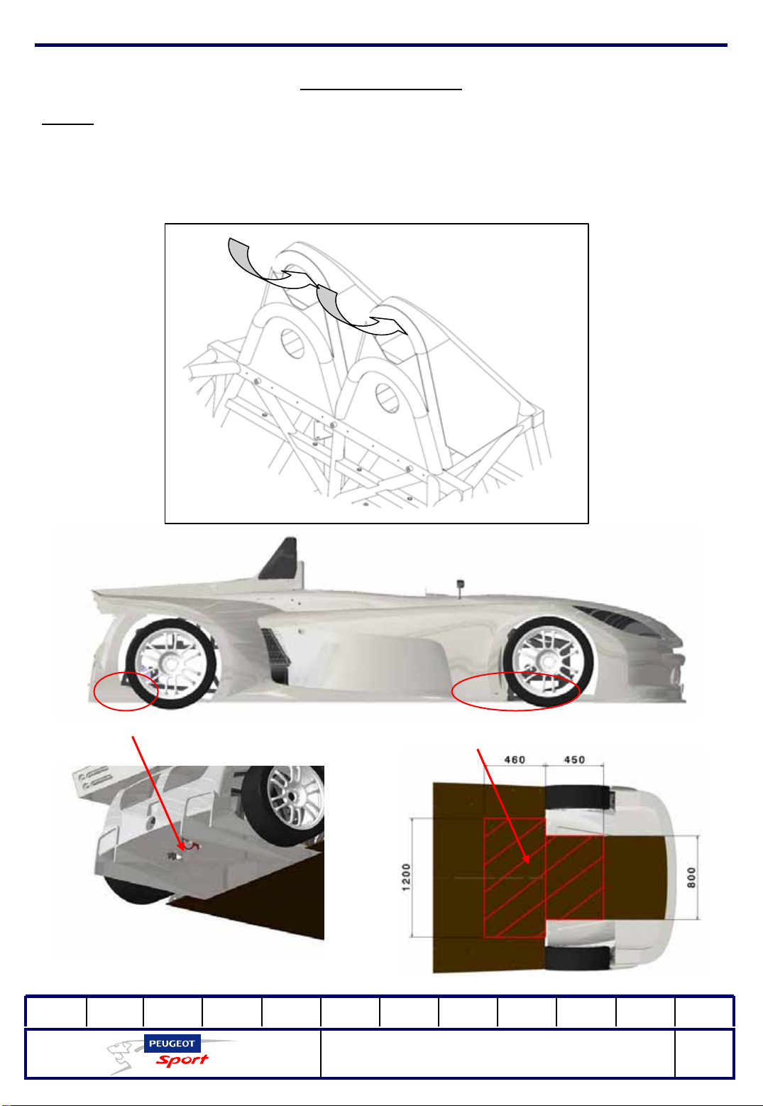
Lifting:
The Spider can be raised with a jib crane, by passing a strap through the
opening of the two main arches or with a "quick lift" (sold separately), following
the areas shown below.
Lifting from the
rear
01Ed. :
Lifting from the
front
207 Spider Technical Instructions
NOT 207 SPI-80
9
Page 11
Ce document est la propriété de Peugeot Sport et ne peut être reproduit ou communiqué sans autorisation.
This document is the property of Peugeot Sport and may not be copied o r circulated without permission .
General points
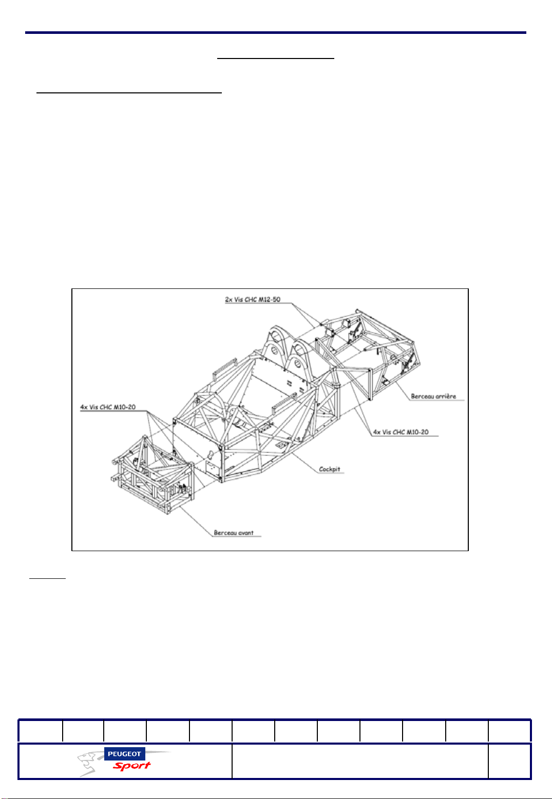
Assembling the tubular chassis:
207 Spider's tubular chassis consists of three parts:
-front cradle
- cockpit chassis
-rear cradle.
No modifications or repairs of any type whatsoever are authorised on the three
parts that make up the tubular chassis.
You must go to the service provider approved by Peugeot Sport for repairs to
these three parts.
Note:
use a product such as Loctite 248 to fit the screws when assembling these
parts together.
Assembling the front cradle onto the cockpit:
- 4 CHC M10-20 screws Tightening torque = 7.6 m.daN
Assembl ing the rear cradle onto the cockpit:
-4 CHC M10-20 screws Tightening torque = 7.6 m.daN
-2 CHC M10-50 screws Tightening torque = 13.3 m.daN
01Ed. :
207 Spider Technical Instructions
NOT 207 SPI-80
10
Page 12
Ce document est la propriété de Peugeot Sport et ne peut être reproduit ou communiqué sans autorisation.
This document is the property of Peugeot Sport and may not be copied o r circulated without permission .
General points
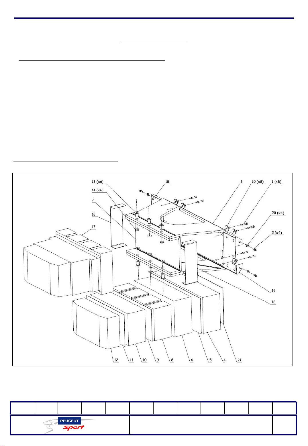
Front impact-absorbent structure (crash box
):
The structure of 207 Spider is impact-absorbent in the front and is joined to the
chassis. This is attached to the front cradle using the following fastenings:
-Crash box front attachment on the front cradle:
8 CHC M8x60 screws tightening torque = 3.5 m. daN
-Crash box side attachment on the front cradle:
4 CHC M8x25 screws tightening torque = 3.5 m. daN
4 alignment washers
Exploded view of the crash box
Important note: The NIDA blocks (4 and 6) are stuck with silicone.
01Ed. :
207 Spider Technical Instructions
NOT 207 SPI-80
11
Page 13
Ce document est la propriété de Peugeot Sport et ne peut être reproduit ou communiqué sans autorisation.
This document is the property of Peugeot Sport and may not be copied o r circulated without permission .
General points
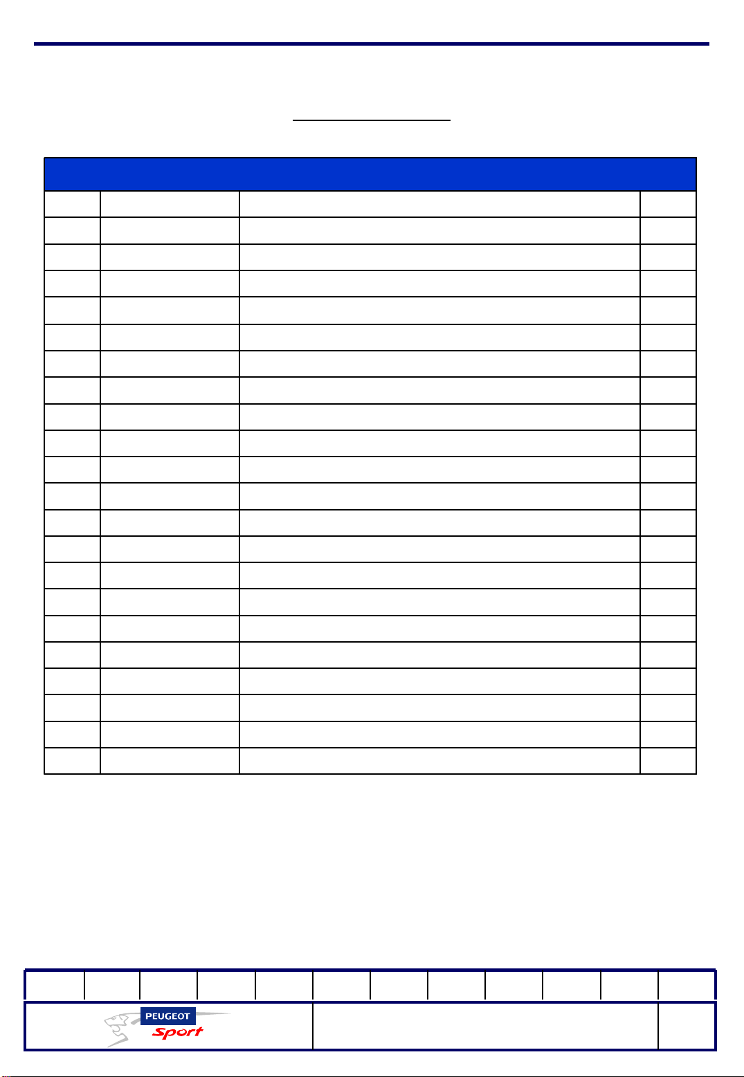
Crash box
QtyPartReferenceNo
8CHC M8 x 60 ISO 4762 SCREW903940128A1
4M8x25 ISO 4762 SCREW903917138A2
1CRASH BOX SHELL903912148D3
1CRASH BOX 5903912158B4
1CRASH BOX SEPARATION PLATE 3903912168B5
1CRASH BOX 4903912178B6
1CRASH BOX MOBILE PLATE903912188A7
1CRASH BOX 3903912198B8
1CRASH BOX SEPARATION PLATE 2903912208B9
1CRASH BOX 2903912218B10
1CRASH BOX SEPARATION PLATE 1903912228B11
1CRASH BOX 1903912238B12
6COIL WASHER OF THE CRASH BOX MOBILE PLATE903912248B13
6COIL WASHER OF THE SHELL MOBILE PLATE 903915348B14
8CRASH BOX ATTACHMENT COIL903912258B15
2CRASH BOX SIDE REINFORCING PLATE903912268A16
1CRASH BOX SHELL903912448A17
1CRASH BOX INSIDE RIGHT REINFORCING PLATE903915288C18
903915338C19
903915358A20
CRASH BOX INSIDE LEFT REINFORCING PLATE
COIL ON THE INTERIOR REINFORCEMENT SIDE OF
CRASH BOX
1
4
1CRASH BOX BOTTOM PLATE903917918A21
NB: in the event of even minimum impact to the front absorbent structure, it must be
expertly assessed by Peugeot Sport.
01Ed. :
207 Spider Technical Instructions
NOT 207 SPI-80
12
Page 14
Ce document est la propriété de Peugeot Sport et ne peut être reproduit ou communiqué sans autorisation.
This document is the property of Peugeot Sport and may not be copied o r circulated without permission .
Equipment
Seat moulding:
207 Spider is sold without a seat. Therefore, the seat must be moulded to the
driver's size from expanding, dual-component polyurethane foam according
to the process outline below. Approximately 1 kg of each component is used;
they are mixed in equal proportions. For your information, you should multiply
the quantity by 25 for the final volume.
Operating procedure:
With the vehicle on a flat surface, have the driver sit in and adjust his height with
one or more hard foam bolsters. Make sure that the regulations explained
below are complied with.
Place a plastic bag with a capacity of at least 130 litres (such as a refuse sack)
under the driver's body in the driving position for moulding, with the opening
to the top and insert the foam bolsters into the bag.
Loosen the harness straps so that you do not obstruct the foam from expanding.
Mix the two reagents in a bucket and pour the liquid into the liner.
Make sure that the foam spreads correctly, especially under the driver's legs and
around the back, then maintain the driver in his position for about ten
minutes.
As soon as the foam has hardened sufficiently (15 to 20 minutes), the driver can
get out of the car. Use a marker to mark up where to cut out for the harness
straps.
Take out the marked up parts and the plastic seat liner.
The foam can be covered with reinforced Scotch guard.
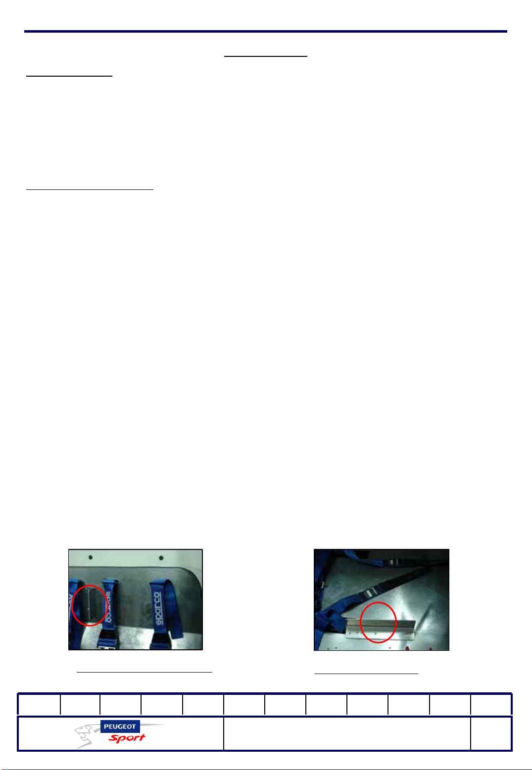
The seat can be locked sideways with angles riveted to the seat back and the
floor.
Angle on the seat back
01Ed. :
Angle on the floor
207 Spider Technical Instructions
NOT 207 SPI-80
13
Page 15
Ce document est la propriété de Peugeot Sport et ne peut être reproduit ou communiqué sans autorisation.
This document is the property of Peugeot Sport and may not be copied o r circulated without permission .
Equipment
Important:
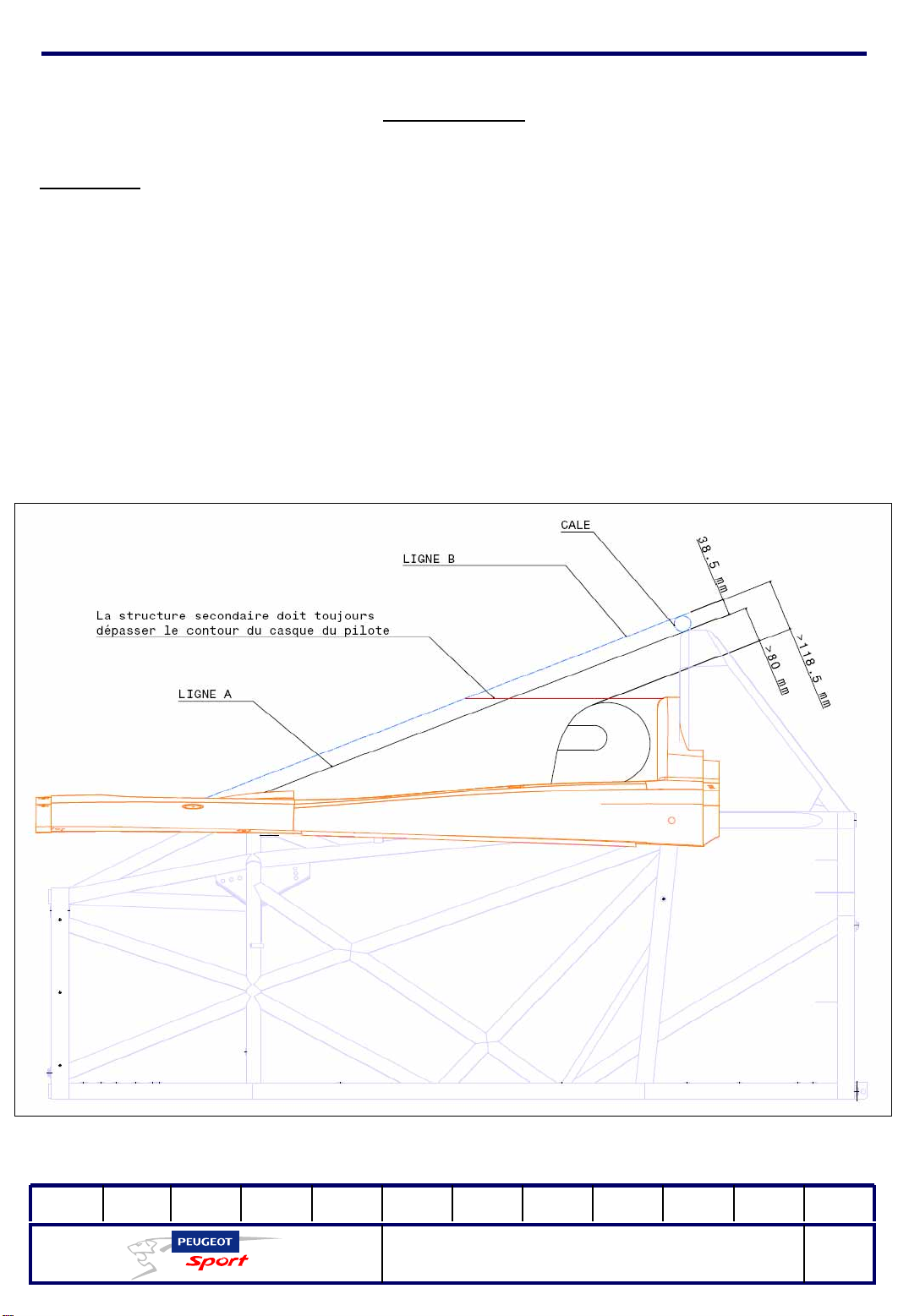
When moulding the seat, the helmet of the driver seated behind the wheel must be
at least 80 mm distant from Line A linking the top of the front and rear structures (Art.
258A.16.1.1). To mould the bucket seat with the car body installed, you can take the
line linking the camber of the body (above the front bow) to the rear bow, using a
38.5mm shim, of about the same thickness (Line B). In this case, the helmet must be
at least 118.5mm from this line.
Furthermore, viewed from the front, the secondary structure must always exceed
the contour of the driver's helmet. (Art. 258A.16.1.2)
01Ed. :
207 Spider Technical Instructions
NOT 207 SPI-80
14
Page 16
Ce document est la propriété de Peugeot Sport et ne peut être reproduit ou communiqué sans autorisation.
This document is the property of Peugeot Sport and may not be copied o r circulated without permission .
Equipment
Harness:
207 Spider is equipped with a SPARCO 04796H 6-point harness.
The shoulder straps are attached with 2 M8 nuts on the frame of the seat back.
Depending on the size of the driver, the straps can be attached in either the top or
bottom position, using the openings on the aluminium cladding of the seat back.
The two lap straps and the two leg straps are also attached to the chassis base with
M8 nuts. Each strap has 3 length attachment positions. A spacer is fitted to the leg
strap nuts to ensure rotation.
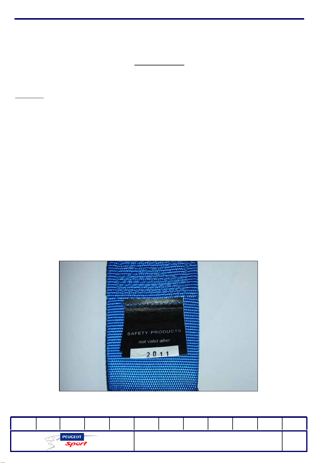
The validity date and condition of the harness must be checked (see regulations in
force).
See the manufacturer's label (photo below)
01Ed. :
207 Spider Technical Instructions
NOT 207 SPI-80
15
Page 17
Ce document est la propriété de Peugeot Sport et ne peut être reproduit ou communiqué sans autorisation.
This document is the property of Peugeot Sport and may not be copied o r circulated without permission .
Equipment
Fire extinguisher
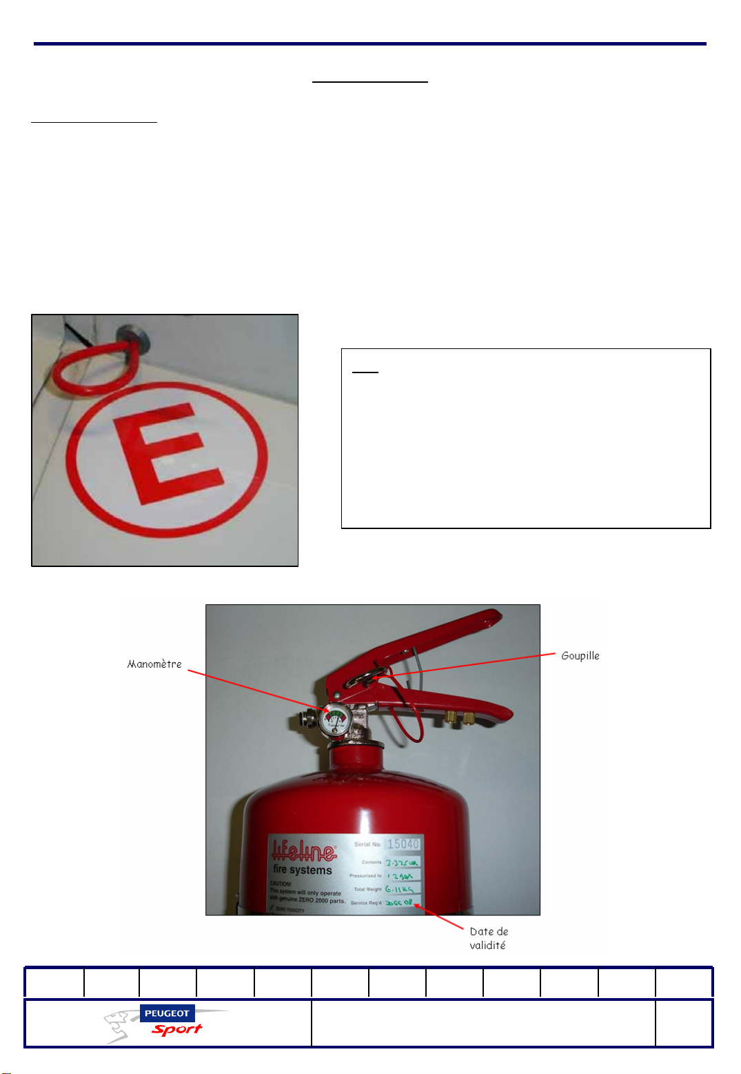
The fire extinguisher provided as standard on 207 Spider is a mechanically-
triggered 4-litre LIFELINE ZERO 2000.
The driver can activate the extinguisher from the inside with the handle. It is
activated from the outside by a pull cable shown by a decal (white E on a red
background) on the right-hand side of the car, near the rear bo w.
NB:
The pin on the handle must be removed
before each race.
The extinguisher validity date and pressure
(pressure gauge) should be checked for
each race.
01Ed. :
207 Spider Technical Instructions
NOT 207 SPI-80
16
Page 18
Ce document est la propriété de Peugeot Sport et ne peut être reproduit ou communiqué sans autorisation.
This document is the property of Peugeot Sport and may not be copied o r circulated without permission .
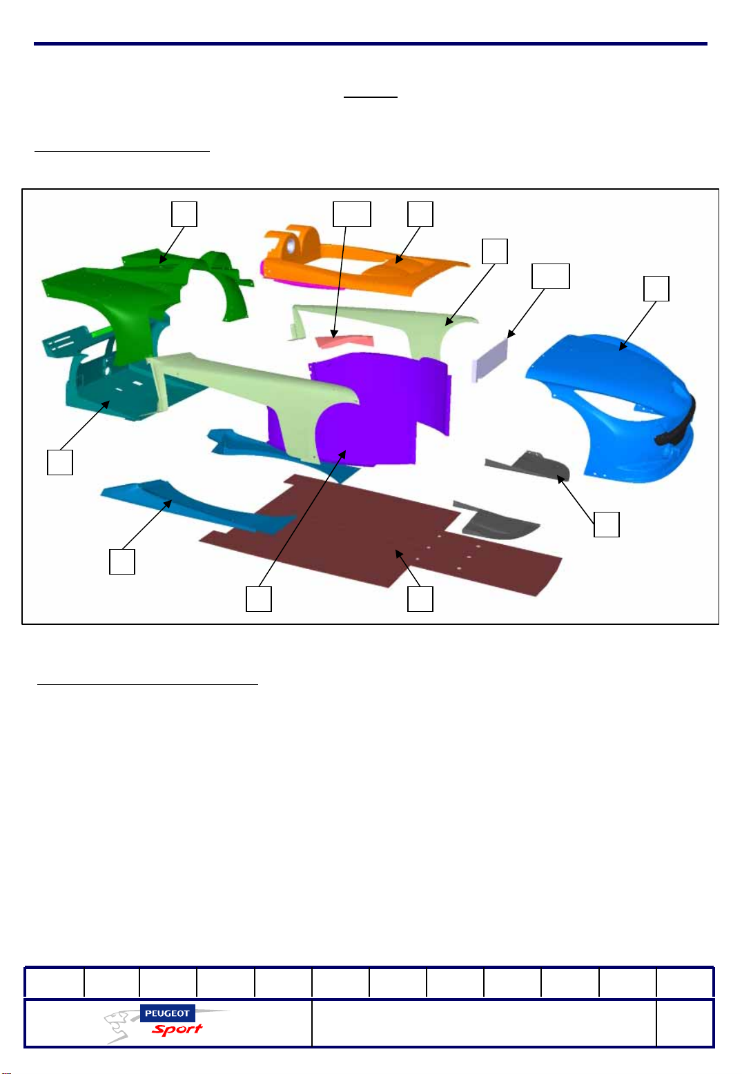
The parts of the body:
Body
9
3
5
10 6
7
11
8
2
14
Exploded view of the body:
1: Flat base
2: Front diffusers
3: Extractor
4: Side radiator ducts
5: Lower radiator ducts
6: Cockpit
7: Wings
8: Bonnet
9: Hood
10: Upper radiator duct
11: Cockpit cover plate
01Ed. :
207 Spider Technical Instructions
NOT 207 SPI-80
17
Page 19
Ce document est la propriété de Peugeot Sport et ne peut être reproduit ou communiqué sans autorisation.
This document is the property of Peugeot Sport and may not be copied o r circulated without permission .
Body
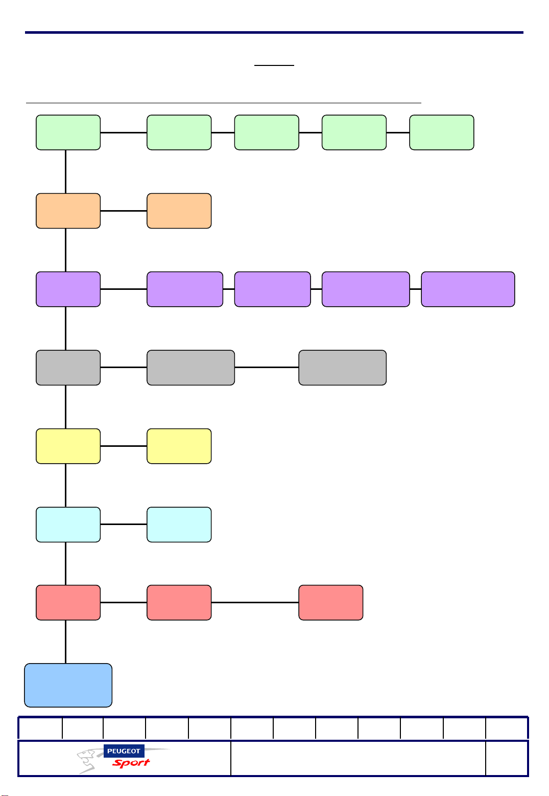
The following is the order for assembling and dismantling the body:
1
3 Front
4 Lower rad
Front
cradle
Flat base2
diffusers
ducts
Cockpit
chassis
Extractor Side rad ducts Cockpit cover
Upper rad duct
Rear
cradle
Crash box
plate
5 Cockpit
6 Wings
7 Bonnet Hood
8
207 Spider
01Ed. :
207 Spider Technical Instructions
NOT 207 SPI-80
18
Page 20
Ce document est la propriété de Peugeot Sport et ne peut être reproduit ou communiqué sans autorisation.
This document is the property of Peugeot Sport and may not be copied o r circulated without permission .
Body
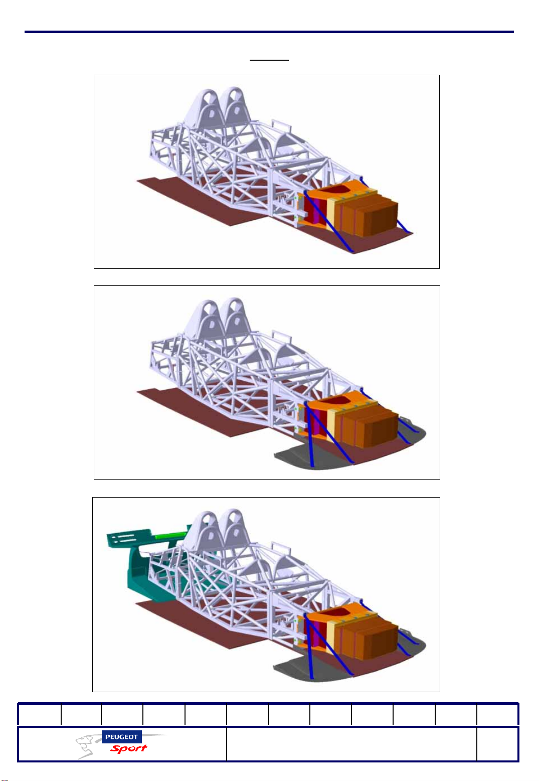
1: Flat base
2: Front diffusers
3: extractor
01Ed. :
207 Spider Technical Instructions
NOT 207 SPI-80
19
Page 21
Ce document est la propriété de Peugeot Sport et ne peut être reproduit ou communiqué sans autorisation.
This document is the property of Peugeot Sport and may not be copied o r circulated without permission .
Body
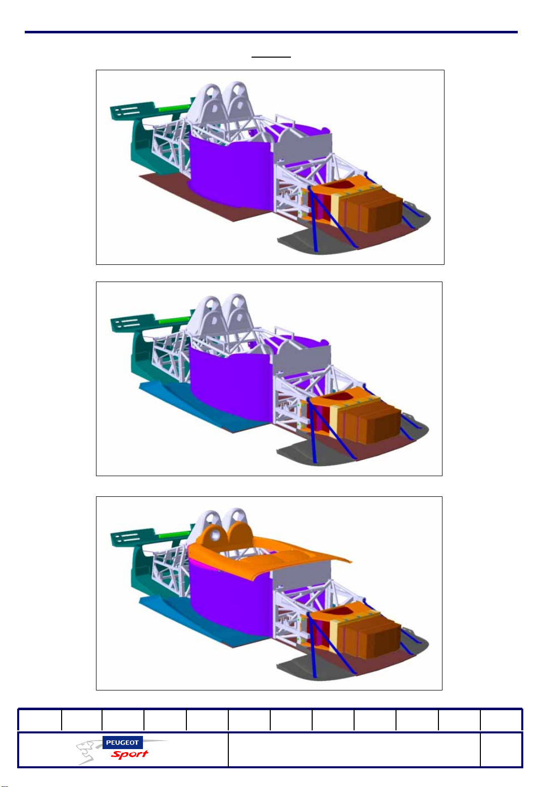
4: Side radiator ducts
5: Lower radiator ducts
6: Cockpit
01Ed. :
207 Spider Technical Instructions
NOT 207 SPI-80
20
Page 22
Ce document est la propriété de Peugeot Sport et ne peut être reproduit ou communiqué sans autorisation.
This document is the property of Peugeot Sport and may not be copied o r circulated without permission .
Body
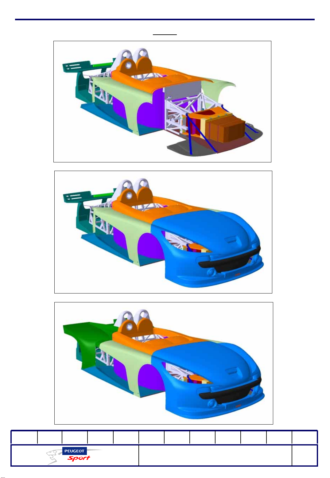
7: Wings
01Ed. :
8: Bonnet
9: Hood
207 Spider Technical Instructions
NOT 207 SPI-80
21
Page 23
Ce document est la propriété de Peugeot Sport et ne peut être reproduit ou communiqué sans autorisation.
This document is the property of Peugeot Sport and may not be copied o r circulated without permission .
Body
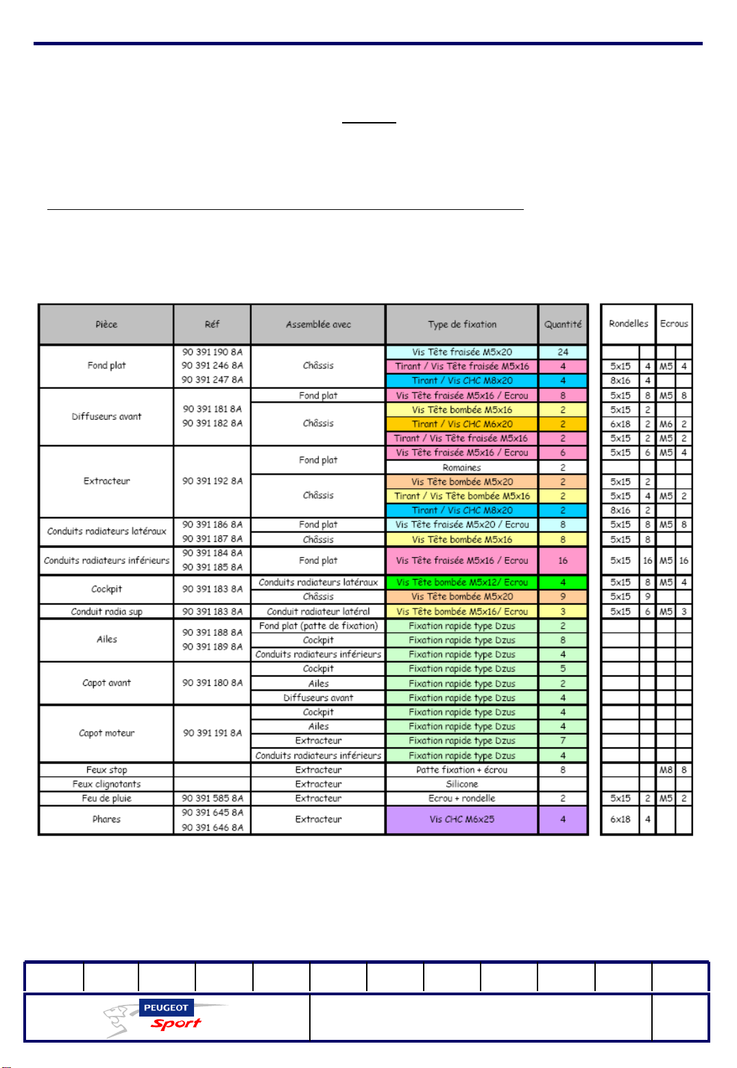
Overview of the fastenings to use to attach the body parts:
01Ed. :
207 Spider Technical Instructions
NOT 207 SPI-80
22
Page 24
Ce document est la propriété de Peugeot Sport et ne peut être reproduit ou communiqué sans autorisation.
This document is the property of Peugeot Sport and may not be copied o r circulated without permission .
Body
Unlike the genuine body parts, the spare parts given above are sold pre-drilled, but
without the fittings (quarter turn).
Please follow the following recommendations for their use.
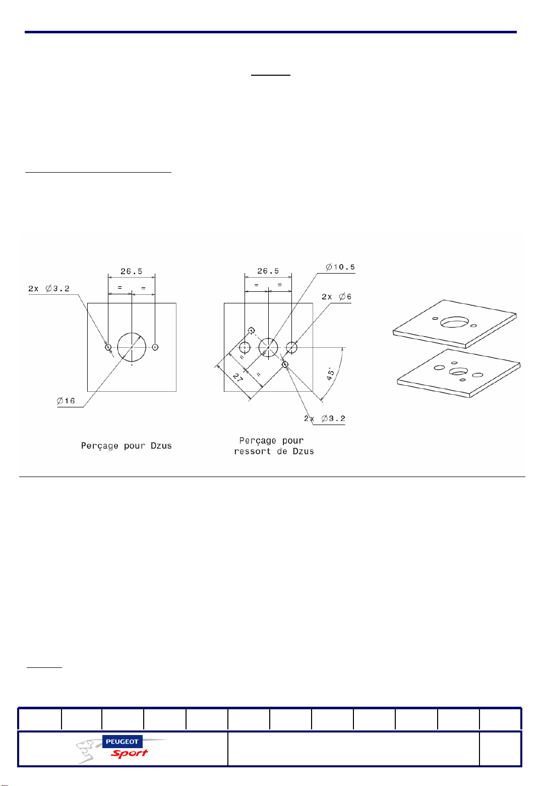
Fitting the dzus (1/4 turn):
The body mountings on the 207 Spider are Dzus EHF 55 with S5-375 springs. The
recommended drillings are:
Each part is attached to the body with the following rivets:
- Dzus: 2 standard 3x8 aluminium rivets
-Dzus springs: 2 countersunk head 3x12 aluminium rivets
The springs are mounted on a 45° or 90° axis relative to the Dzus axis (depending on
the part).
Do a joint test after assembling the two parts. If the Dzus is too hard to tighten,
compress the spring slightly.
Note:
The Dzus rivet head can be flattened.
01Ed. :
207 Spider Technical Instructions
NOT 207 SPI-80
23
Page 25
Ce document est la propriété de Peugeot Sport et ne peut être reproduit ou communiqué sans autorisation.
This document is the property of Peugeot Sport and may not be copied o r circulated without permission .
Electrical
Assembly of the electrical accessories:
Battery:
The battery on the 207 Spider is a RED TOP 20. It is located inside the cockpit
(against the front plate) on the passenger side and held in place with foam.
It is protected by an aluminium housing screwed to the chassis with 3 M8 screws
with a cover made from a fibreglass/polyester composite fibre to ensure the seal.
Cut-out switch:
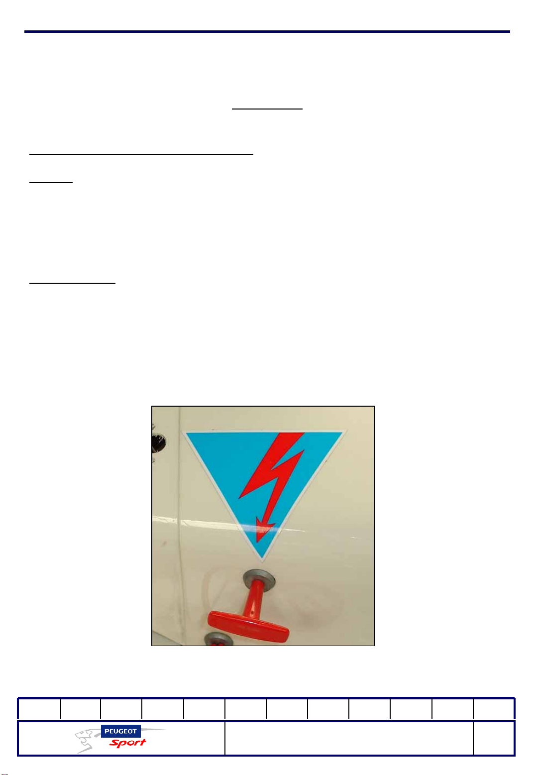
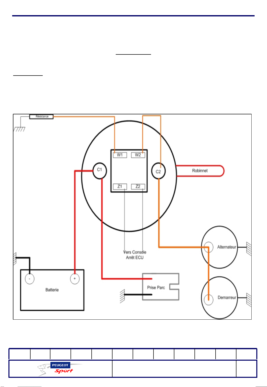
There is a cut-out switch located inside the cockpit, within easy reach of the driver.
The power supply can be cut off either from the inside by turning the red key, or
from the outside, by pulling the handle marked with a decal (red lightning bolt in a
blue triangle) on the right-hand side of the car, near the rear bow.
01Ed. :
207 Spider Technical Instructions
NOT 207 SPI-80
24
Page 26
Ce document est la propriété de Peugeot Sport et ne peut être reproduit ou communiqué sans autorisation.
This document is the property of Peugeot Sport and may not be copied o r circulated without permission .
Electrical
Important:
It is compulsory to fit the resistor provided with the cut-out switch.
01Ed. :
207 Spider Technical Instructions
NOT 207 SPI-80
25
Page 27
Ce document est la propriété de Peugeot Sport et ne peut être reproduit ou communiqué sans autorisation.
This document is the property of Peugeot Sport and may not be copied o r circulated without permission .
Electrical
Infrared sensor:
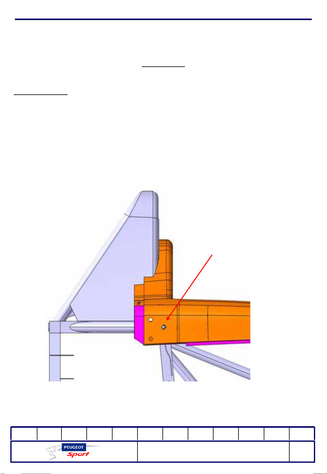
The Spider is fitted with an on-board chronometer (not official). Depending on the
direction of the race circuits, position t he infrared sensor on the right side for the
system to function.
The cockpit has two holes symmetrically opposite each other (see the diagram
below) for this purpose.
For each Peugeot Sport event, place a unit at the side of the track (stand side).
Infrared sensor
01Ed. :
207 Spider Technical Instructions
NOT 207 SPI-80
26
Page 28
Ce document est la propriété de Peugeot Sport et ne peut être reproduit ou communiqué sans autorisation.
This document is the property of Peugeot Sport and may not be copied o r circulated without permission .
Electrical
Data socket:
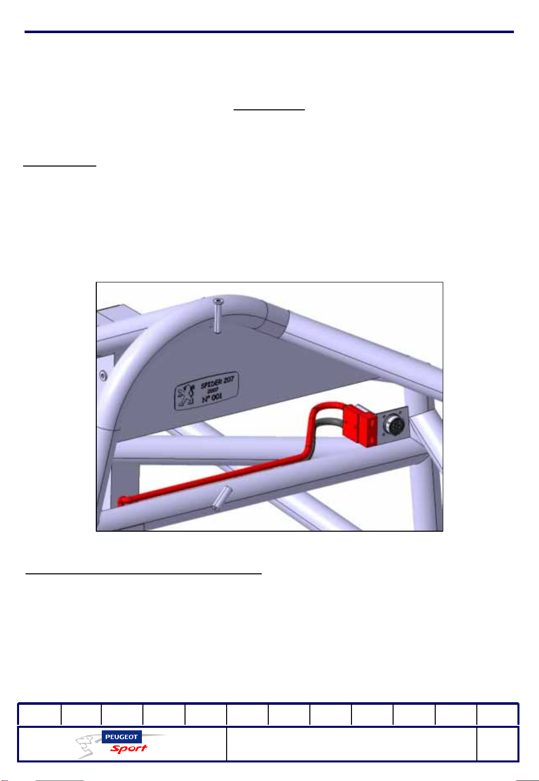
Spider is fitted with a data socket and a socket for a park battery. They are fitted on
the front right bow.
The data socket is reserved exclusively for use by Peugeot Sport technical officers.
Transponder for the official chronometer:
It is compulsory to have a transponder for the official timing
of the qualifying rounds and races (see the technical rule for the type and supplier
of this product).
Use the wiring bundle and its connector provided to power the transponder.
It is located under the bonnet (on the right in the front around the upper clevis area
of the shock absorber).
01Ed. :
207 Spider Technical Instructions
NOT 207 SPI-80
27
Page 29
Ce document est la propriété de Peugeot Sport et ne peut être reproduit ou communiqué sans autorisation.
This document is the property of Peugeot Sport and may not be copied o r circulated without permission .
Electrical
Multifunction screen:
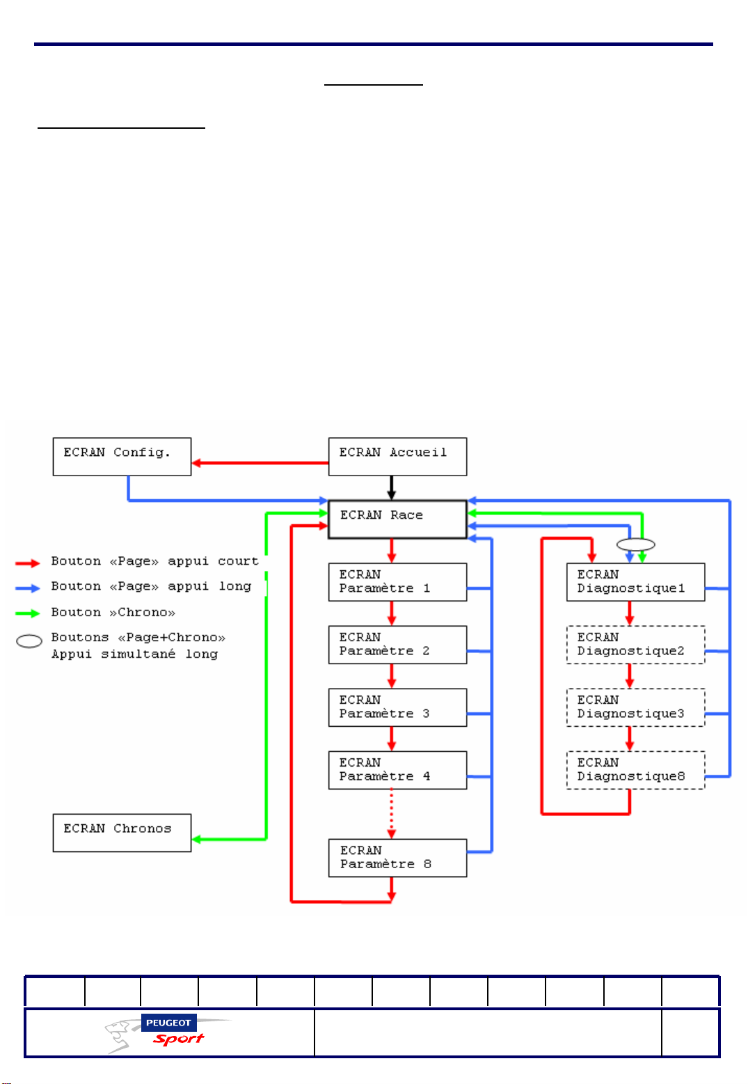
The 207 Spider welcome screen is displayed for 3 seconds when you turn on the
system, if the engine speed is zero.
This is followed by the race screen.
There are three additional types of screen that can be accessed using the Menu
and Chrono buttons:
-Chrono
- parameters
-diagnostic
Screen sequencing diagram:
01Ed. :
207 Spider Technical Instructions
NOT 207 SPI-80
28
Page 30
Ce document est la propriété de Peugeot Sport et ne peut être reproduit ou communiqué sans autorisation.
This document is the property of Peugeot Sport and may not be copied o r circulated without permission .
Electrical
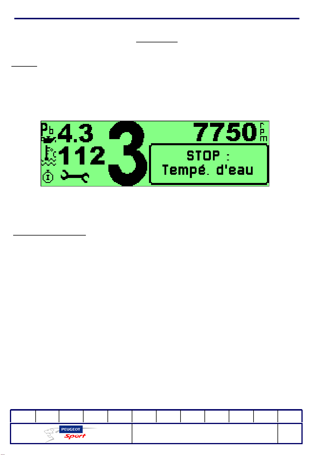
Race screen:
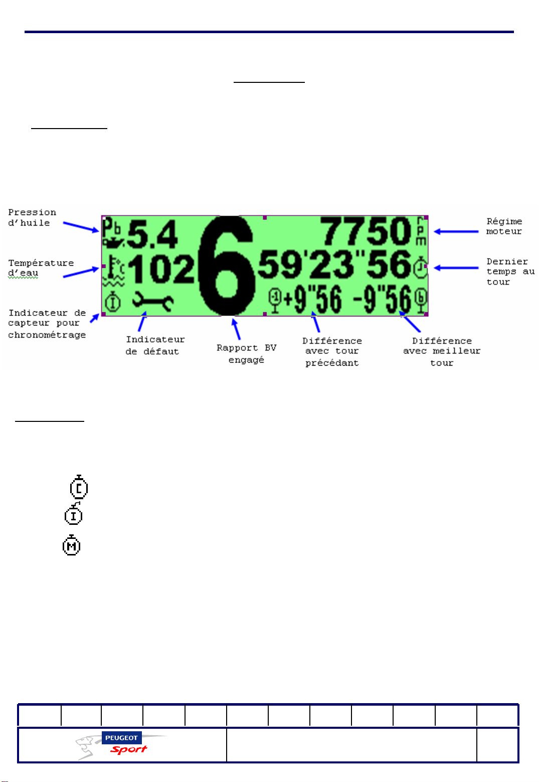
This screen is displayed automatically after the welcome screen or the
configuration screen.
Parameters:
The Water Temperature or Oil Pressure icons flash when there is an abnormal reading.
The four icons below are used by the sensor indicator for the chronometer:
A sensor is connected to the data logger and the display is configured to
time from a CAN frame received from the data logger.
An infrared sensor is connected to the display and a CAN frame is sent to
the data logger at each top marker.
A magnetic sensor is connected to the display and a CAN frame is sent to
the data logger at each top marker.
01Ed. :
207 Spider Technical Instructions
NOT 207 SPI-80
29
Page 31
Ce document est la propriété de Peugeot Sport et ne peut être reproduit ou communiqué sans autorisation.
This document is the property of Peugeot Sport and may not be copied o r circulated without permission .
Electrical
The display has not detected any sensor connected and therefore
the chronometer is not active.
The key plate display indicates that the system has detected a fault (at least one
fault code present in the diagnostic system).
The fault code must be located using the diag screen when you next return to the
stand.
If the default requires you to stop immediately, the system will display a warning
pop-up message (chronometer field) showing the exact nature of the fault.
EMF displays the icon corresponding to the gear: ‘R’,’N’,’1’, ‘2’, ‘3’, ‘4’, ‘5’, ‘6’, ’?’.
R = reverse
N = neutral
?= gear not determined
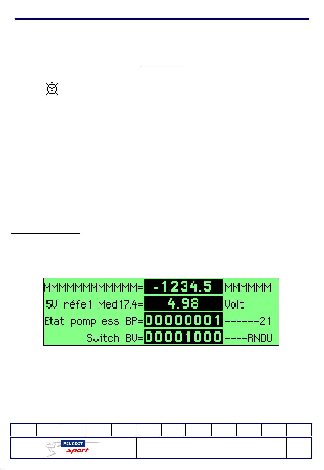
Screen parameters:
This screen displays 4 parameters on 4 lines:
You use the 8 "Parameters" screens to view the 32 engine or gearbox parameters.
01Ed. :
207 Spider Technical Instructions
NOT 207 SPI-80
30
Page 32

Ce document est la propriété de Peugeot Sport et ne peut être reproduit ou communiqué sans autorisation.
This document is the property of Peugeot Sport and may not be copied o r circulated without permission .
Electrical
Parameter details:
The detail of the 30 parameters displayed on the 8 pages of the DIAGS screen is
accessible from the Race screen: simply press the Menu key.
1-Diags
The diagnostic frame is input by the ECU.
If the frame is at zero, there are no faults detected. If not, the number of faults
detected is shown cyclically.
2-VBatt
Battery voltage in Volts.
3-Switches
Information to check the correct operati on of all the digital inputs to the ECU .
- 0: no digital input activated, nominal value for the car while running.
- 1: digi tal input no. 1 of the GEARBOX UP SHIFT switch is activated (request to
move up gears).
- 2: digi tal input no. 2 of the GEARBOX DOWN SHIFT switch is activated (request
to move down gears).
- 4: GEARBOX Neutral switch digital input is activated (put in neutral)
- 8: Console GEARBOX Reverse switch digital input is activated (reverse)
- 16: Console MENU key digital input is activated.
When the ignition is switched off, the SWITCHES information is at 3 (inputs 1 and 2 of
the CONTACT switch are activated; 1 + 2 = 3).
If you pull the gear lever (which activates the GEARBOX switch), the information
changes to 7 (1+2+4 ), and so on for all the possible combinations.
4-PosPed
Position of the accelerator pedal as a % of pedal depression.
01Ed. :
207 Spider Technical Instructions
NOT 207 SPI-80
31
Page 33

Ce document est la propriété de Peugeot Sport et ne peut être reproduit ou communiqué sans autorisation.
This document is the property of Peugeot Sport and may not be copied o r circulated without permission .
Electrical
5 – PosPap
Position of the electronic throttle valve in ° of opening.
6 – Posbar
Position of the cylinder in mV.
7 - Gearbox compression
Gear selected. If the gear is not properly selected (in between two gears), the gear
7 will be displayed (which is ?on the Race screen)
8 - Med17.4 5Vref1
Value in volts of the no. 1 5-V power supply to the ECU
9 - MED17.4 5Vref2
Value in volts of the no. 2 5-V power supply to the ECU.
10 – PSural
Intake pressure in mbar.
11 - TSural
Temperature in the intake in °C
12 – PAdm
Reference intake pressure in mbar
13 – TEngine Oil
Engine oil temperature in °C.
14 - TMED17.4
Internal temperature of the BOSCH ECU in °C.
15 – Twater
Temperature of the cooling circuit water in °C
16 - Gmv Status
Status of the cooling fan control.
0: The ECU is not controlling the fan.
1: The ECU is controlling the fan.
01Ed. :
207 Spider Technical Instructions
NOT 207 SPI-80
32
Page 34

Ce document est la propriété de Peugeot Sport et ne peut être reproduit ou communiqué sans autorisation.
This document is the property of Peugeot Sport and may not be copied o r circulated without permission .
Electrical
17 - PetPmpStat
Control status of the low-pressure petro l pump
0: The ECU is not controlling the petrol pump.
1: The ECU is controlling the petrol pump.
18 -PosVVT
Position of the VVT (phase shifter) in crankshaft °.
19 - ConsVVT
VVT reading in crankshaft °.
20 - CmdVVT
Value in % of the Cyclical Opening Ratio of the VVT solenoid valve.
21 -PosPap1
Electrical value of track 1 of the electronic throttle valve in volts.
22 - PosPap2
Electrical value of track 2 of the electronic throttle valve in volts.
23 - PosPed1
Electrical value of track 1 of the accelerator pedal in volts.
24 - PosPed2
Electrical value of track 2 of the accelerator pedal in volts.
25 - MED17.X serial no.
BOSCH ECU serial number
26 - Ptyre
Pressure of the gearbox pneumatic circuit
27 - Ppet
High-pressure petrol pressure
28 - Lambda
Value in mV of the lambda sensor
29 - CplMotDem
Torque requested by the driver
30 - CplmotRéel
Actual torque applied to the engine
31 - TECU
Internal temperature of the Bosch ECM
01Ed. :
207 Spider Technical Instructions
NOT 207 SPI-80
33
Page 35
Ce document est la propriété de Peugeot Sport et ne peut être reproduit ou communiqué sans autorisation.
This document is the property of Peugeot Sport and may not be copied o r circulated without permission .
Electrical
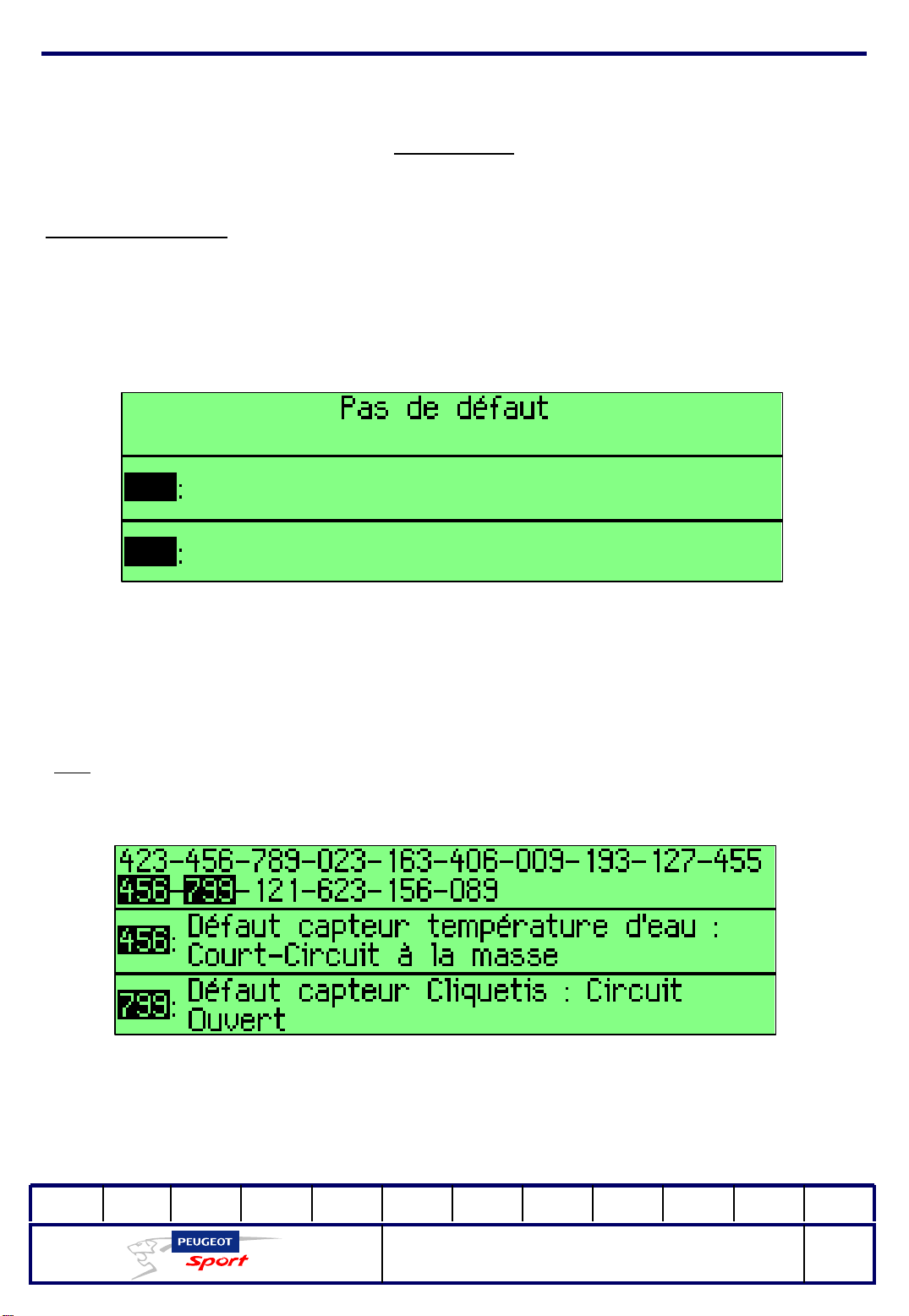
Diagnostic screen:
Use this mode to display and decode the fault code numbers (Diag)
If there are no faults, the "No faults" screen is displayed (see below).
If there is at least one fault, the key is displayed on the Race screen along with a
fault code and relevant decoding.
: if there are 16 faults:
E.g.
Each time you press the "Page" key, the system displays the following two fault codes.
01Ed. :
207 Spider Technical Instructions
NOT 207 SPI-80
34
Page 36
Ce document est la propriété de Peugeot Sport et ne peut être reproduit ou communiqué sans autorisation.
This document is the property of Peugeot Sport and may not be copied o r circulated without permission .
Electrical
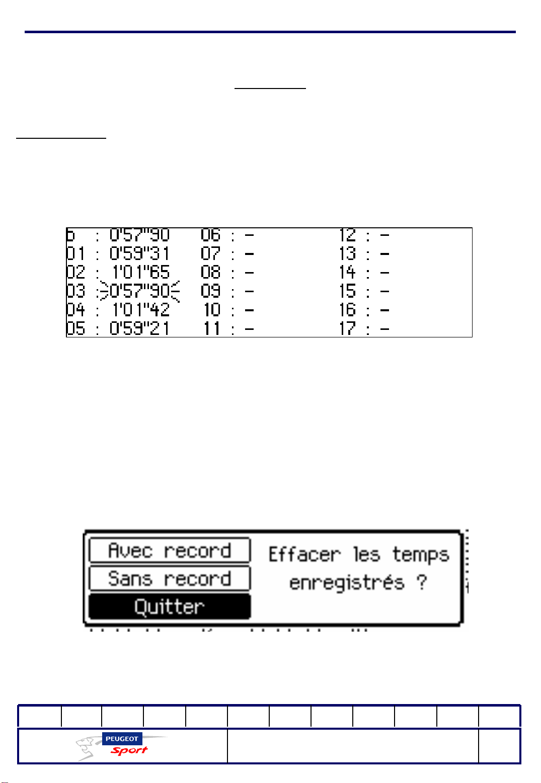
Chrono screen:
The last 17 times along with the best time are stored and displayed on this screen.
The first time "b", is the best reference time.
The best time for the series flashes. This is not necessarily the best reference time.
Press and hold "page" to display a pop-up window to delete the stored times, with or
without the best time. Move the selection with the "chrono" button and press and
hold "page" to validate your selection:
01Ed. :
207 Spider Technical Instructions
NOT 207 SPI-80
35
Page 37
Ce document est la propriété de Peugeot Sport et ne peut être reproduit ou communiqué sans autorisation.
This document is the property of Peugeot Sport and may not be copied o r circulated without permission .
Electrical
Pop up:
The system displays a pop-up window instead of the chrono window, which is useful
for warnings. In the Race screen only: (oil pressure, water temperature, oil
temperature and battery voltage).
Press the "page" button to delete the active pop-up window.
Configuration screen:
Use this screen to modify the following parameters:
- display text language (French or English),
- best round time? ? ?
- delete time for warning pop-up messages,
- screen brightness,
- type of chrono sensor (positive or negative logic magnetic sensor,
infrared, CAN frame from the data logger),
- duration of chrono inhibition (to make sure to only take one top
marker per round, even if there are several markers on the circuit).
Press "chrono" to increment the current parameter.
Press and hold "chrono" to decrement the current parameter.
Press "page" to display the next parameter (loops around again when you reach
the end of the list).
Press and hold "page" to store the configuration and to go to the Race screen.
01Ed. :
207 Spider Technical Instructions
NOT 207 SPI-80
36
Page 38

Ce document est la propriété de Peugeot Sport et ne peut être reproduit ou communiqué sans autorisation.
This document is the property of Peugeot Sport and may not be copied o r circulated without permission .
Electrical
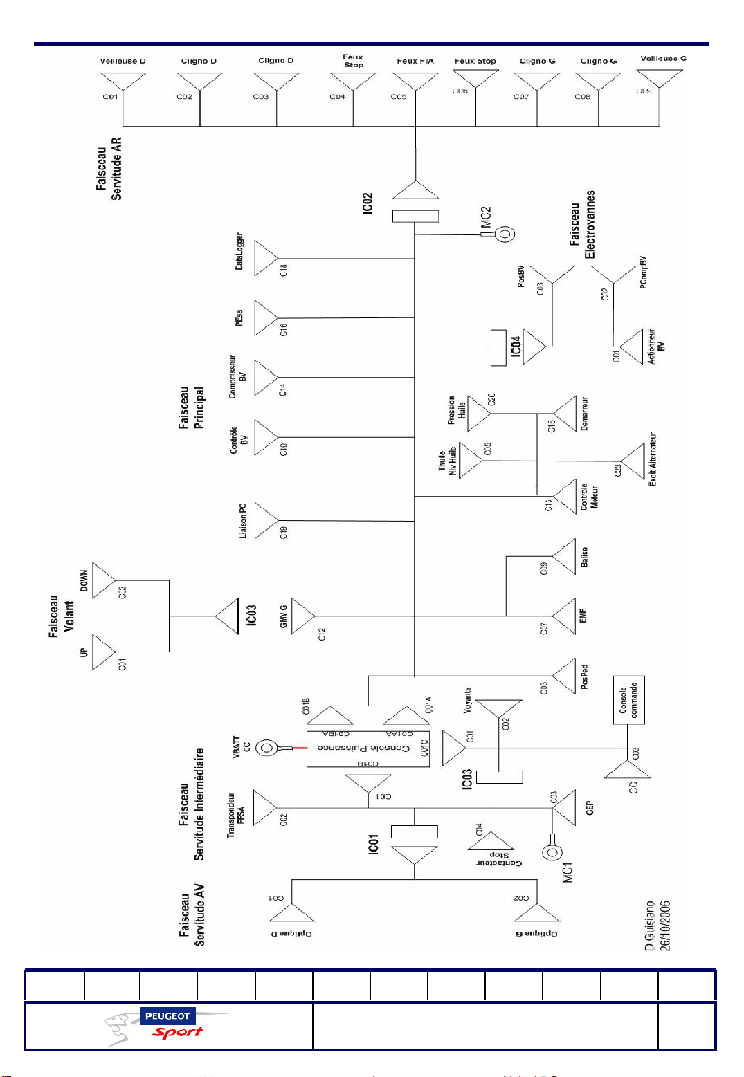
Electrical bundles
The wiring bundles on the 207 Spider are specific to the car. Under no circumstances
may they be changed or modified.
Splicing or the addition of additional bundles not delivered with the vehicle are not
authorised.
207 Spider has 9 system bundles:
-front servo bundle
- intermediate servo bundle
- steering wheel bundle
- servo-command bundle
- solenoid valves bundle
- main wiring bundle
- rear servo bundle
- power console bundle
- engine bundle
Wiring bundle diagram:
See the diagram on the next page.
01Ed. :
207 Spider Technical Instructions
NOT 207 SPI-80
37
Page 39
Ce document est la propriété de Peugeot Sport et ne peut être reproduit ou communiqué sans autorisation.
This document is the property of Peugeot Sport and may not be copied o r circulated without permission .
01Ed. :
207 Spider Technical Instructions
NOT 207 SPI-80
38
Page 40
Ce document est la propriété de Peugeot Sport et ne peut être reproduit ou communiqué sans autorisation.
This document is the property of Peugeot Sport and may not be copied o r circulated without permission .
Electrical
Power console
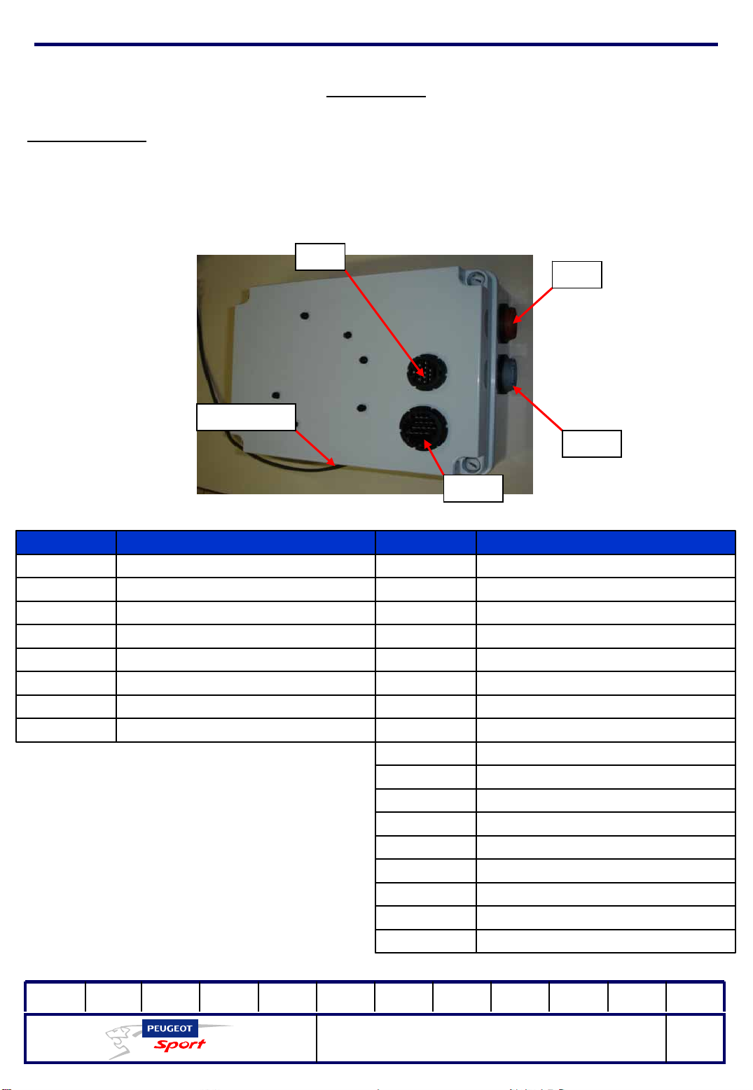
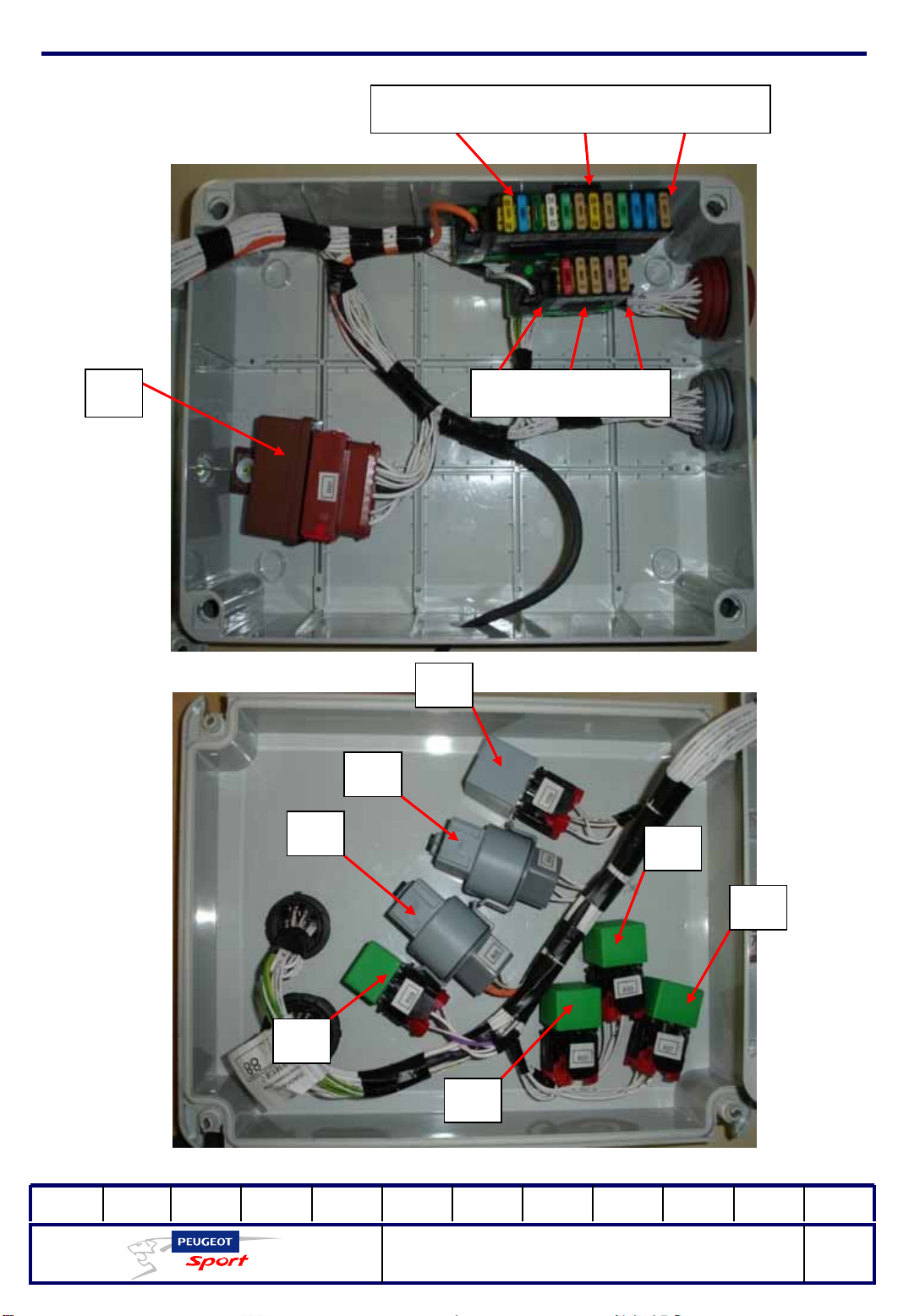
The power console on 207 Spider is a sealed plastic box containing the car's fuses
and relays. It is connected to the system wiring bundles through 4 connectors and
supplied by the V+BATT wire connected to the cut-out switch output.
C01
B
V+BATT
(CC)
C01
C
C01B
A
C01A
A
FuseRefRelayRef
Fan unit G 30A fuseF1Double 2000 relayR01
+APC 15A fuseF2Fan unit G 35A relayR03
Electro-hydraulic steering 40A fuseF3+APC 45A fuseR05
Lights 25A fuseF4Electro-hydraulic steering 45A relayR06
Gearbox compressor 30A fuseF5Lights 25A relayR07
Indicator 5A fuseF6Gearbox compressor 25A fuseR08
Gearbox control 10A fuseF725A warning relayR09
EMF - 5A fuseF8Starter 25A fuseR10
Data-Logger - 5A fuseF9
Position 5A fuseF10
AVC A-main - 20A fuseF12
+12V. ECM - 30A fuseF13
+12V. ECM - 15A fuseF14
15A PPet f useF15
3A transponder fuseF16
5A stop fuseF17
FIA - 5A fire fuseF18
01Ed. :
207 Spider Technical Instructions
NOT 207 SPI-80
39
Page 41
Ce document est la propriété de Peugeot Sport et ne peut être reproduit ou communiqué sans autorisation.
This document is the property of Peugeot Sport and may not be copied o r circulated without permission .
F01-F02-F03-F04-F05-F06-F12-F13-F14-F15-
F18
R01 F07-F08-F09-F16-
F17
R06
R08
R09
R05
R10
R07
R03
01Ed. :
207 Spider Technical Instructions
NOT 207 SPI-80
40
Page 42
Ce document est la propriété de Peugeot Sport et ne peut être reproduit ou communiqué sans autorisation.
This document is the property of Peugeot Sport and may not be copied o r circulated without permission .
Electrical
Controls console:
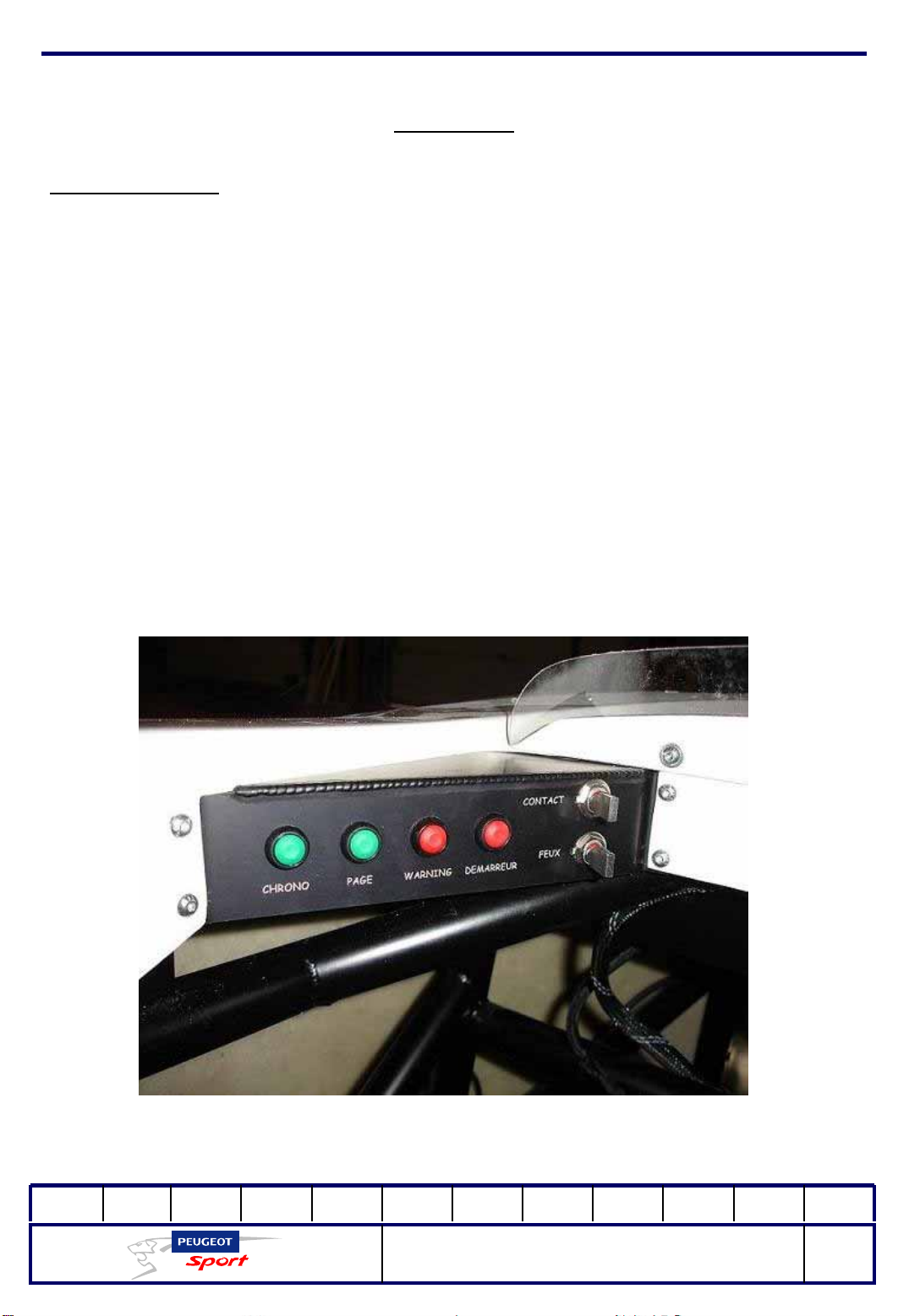
The 207 Spider dashboard consists of 4 sub-units:
- a control panel, to the driver's left
- a multi-function screen at the level of the steering wheel
- an indicator light panel, also at the level of the steering wheel
- A central console along the line of the car's axis
The control panel includes the following functions:
-chrono
- page (see the section on the operation of the multi-function screen)
- warning
-starter
-lights
-switch
01Ed. :
207 Spider Technical Instructions
NOT 207 SPI-80
41
Page 43

Ce document est la propriété de Peugeot Sport et ne peut être reproduit ou communiqué sans autorisation.
This document is the property of Peugeot Sport and may not be copied o r circulated without permission .
Electrical
Presentation of the dash, indicators and central console:
There are three indicators on the dash: Upshift, Alarm and Warning),
the central console consists of 3 push buttons: Neutral, Reverse and Lever (refer to
the section on the gearbox).
Planche de voyants Console centrale
The resistors (150 ohms, 3W) located behind each indicator may not be removed
under any circumstances.
This would cause the indicator lights to stay on permanently. We strongly recommend
coating the welds behind each component with silicone.
01Ed. :
207 Spider Technical Instructions
NOT 207 SPI-80
42
Page 44
Ce document est la propriété de Peugeot Sport et ne peut être reproduit ou communiqué sans autorisation.
This document is the property of Peugeot Sport and may not be copied o r circulated without permission .
Engine
Identification:
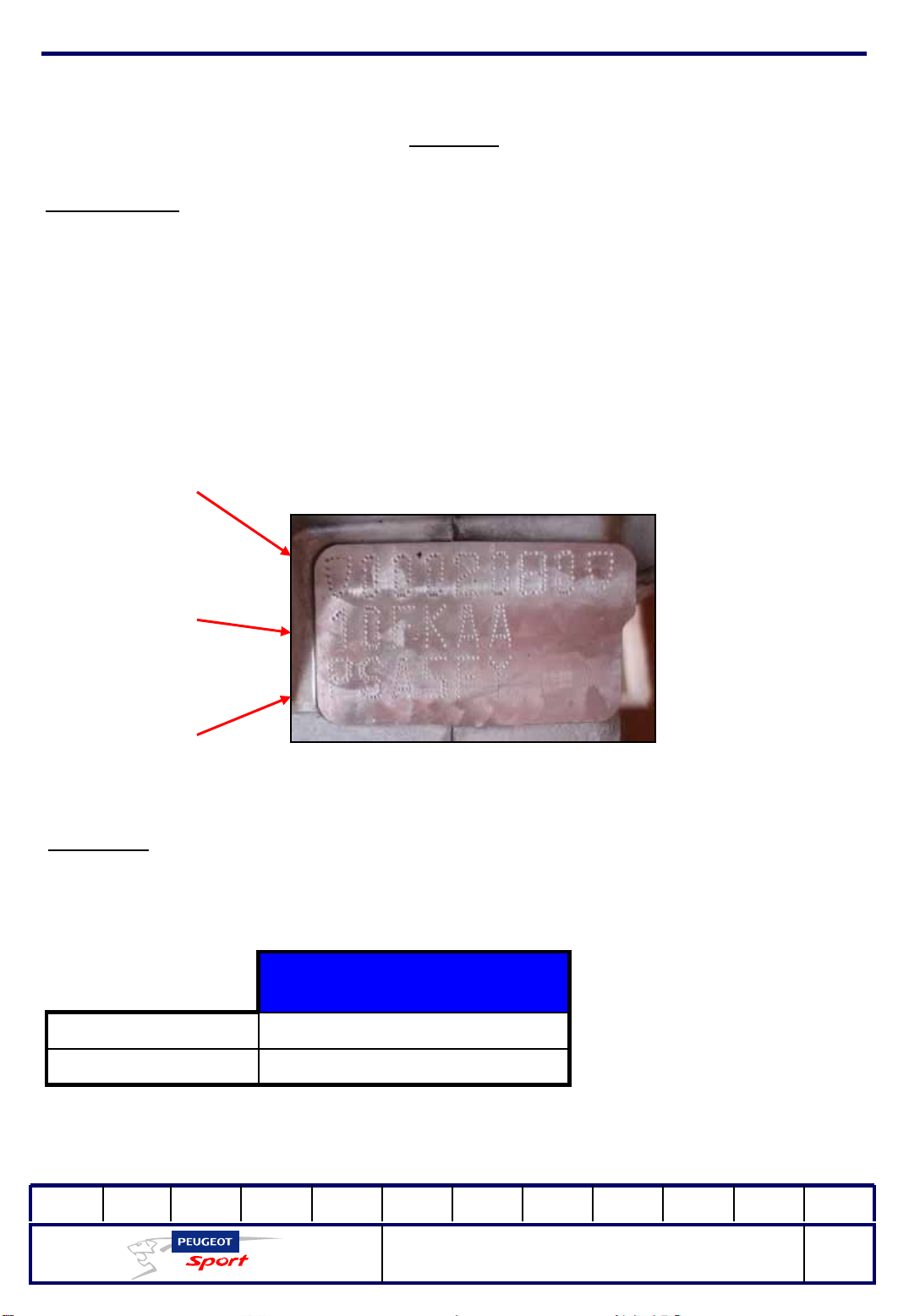
The identification is engraved on the front of the cap housing.
It includes:
- A Regulatory type
- B: Part marking
- C. Serial number
C
B
A
Engine oil:
Only Total 5W30 is allowed.
Capacity of the oil sump
(litres)
4With oil filter
3.7Without oil filter
01Ed. :
207 Spider Technical Instructions
NOT 207 SPI-80
43
Page 45
Ce document est la propriété de Peugeot Sport et ne peut être reproduit ou communiqué sans autorisation.
This document is the property of Peugeot Sport and may not be copied o r circulated without permission .
Engine
Cooling circuit:
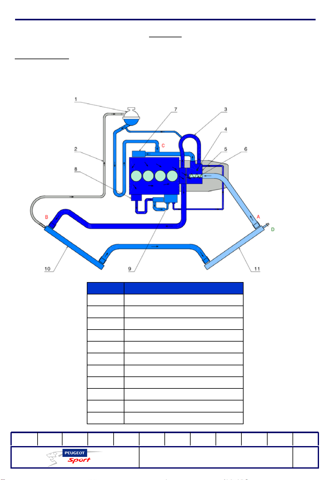
2 radiators placed in series but not symmetrically on either side of the vehicle cool
the car.
Total circuit volume: 6 litres
Composite partMarker
Degassing tank1
Degassing hose2
Heating bridging hose3
Water temperature probe4
Water output unit5
Electronically-controlled thermostat6
Water pump7
Water-oil exchanger8
Additional water pump (turbo)9
Right-hand radiator10
Left-hand radiator11
01Ed. :
207 Spider Technical Instructions
NOT 207 SPI-80
44
Page 46
Ce document est la propriété de Peugeot Sport et ne peut être reproduit ou communiqué sans autorisation.
This document is the property of Peugeot Sport and may not be copied o r circulated without permission .
Engine
Drain/purge the circuit:
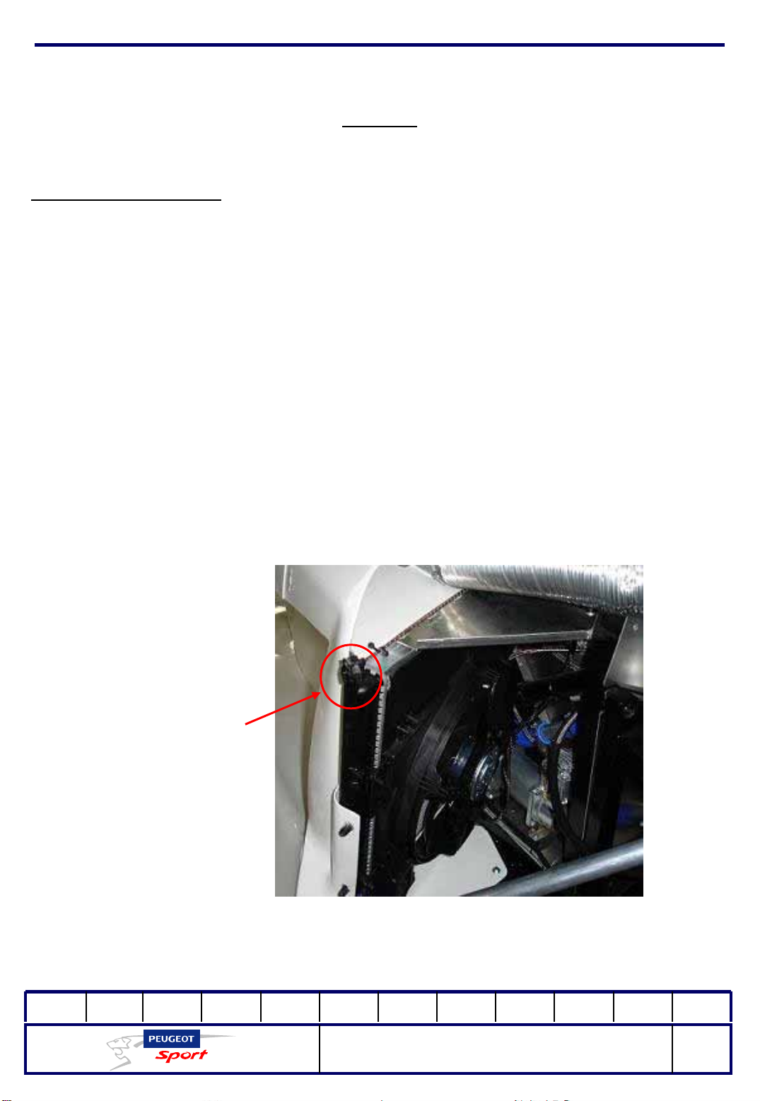
To drain the cooling circuit, disconnect t he 2 radiator hoses located at the outside of
the car (A and B) as well as the water pump input hose (C). You should drain
practically all the coolant from the system.
When reassembling, make sure that the guide bearings are tightened properly,
dismantle the drain hose from the left-hand radiator (as shown in the photo below)
and then refill the circuit through the degassing tank until the liquid comes out
through the drain (with no air). Close the drain and refill the degassing tank . Start the
engine and allow it to heat to the normal temperature, as you gradually fill the
container as it empties. When you reach the point where the level remains the same
and does not lower, fill it to the mark on the container.
Tuyau de purge
01Ed. :
207 Spider Technical Instructions
NOT 207 SPI-80
45
Page 47
Ce document est la propriété de Peugeot Sport et ne peut être reproduit ou communiqué sans autorisation.
This document is the property of Peugeot Sport and may not be copied o r circulated without permission .
Engine
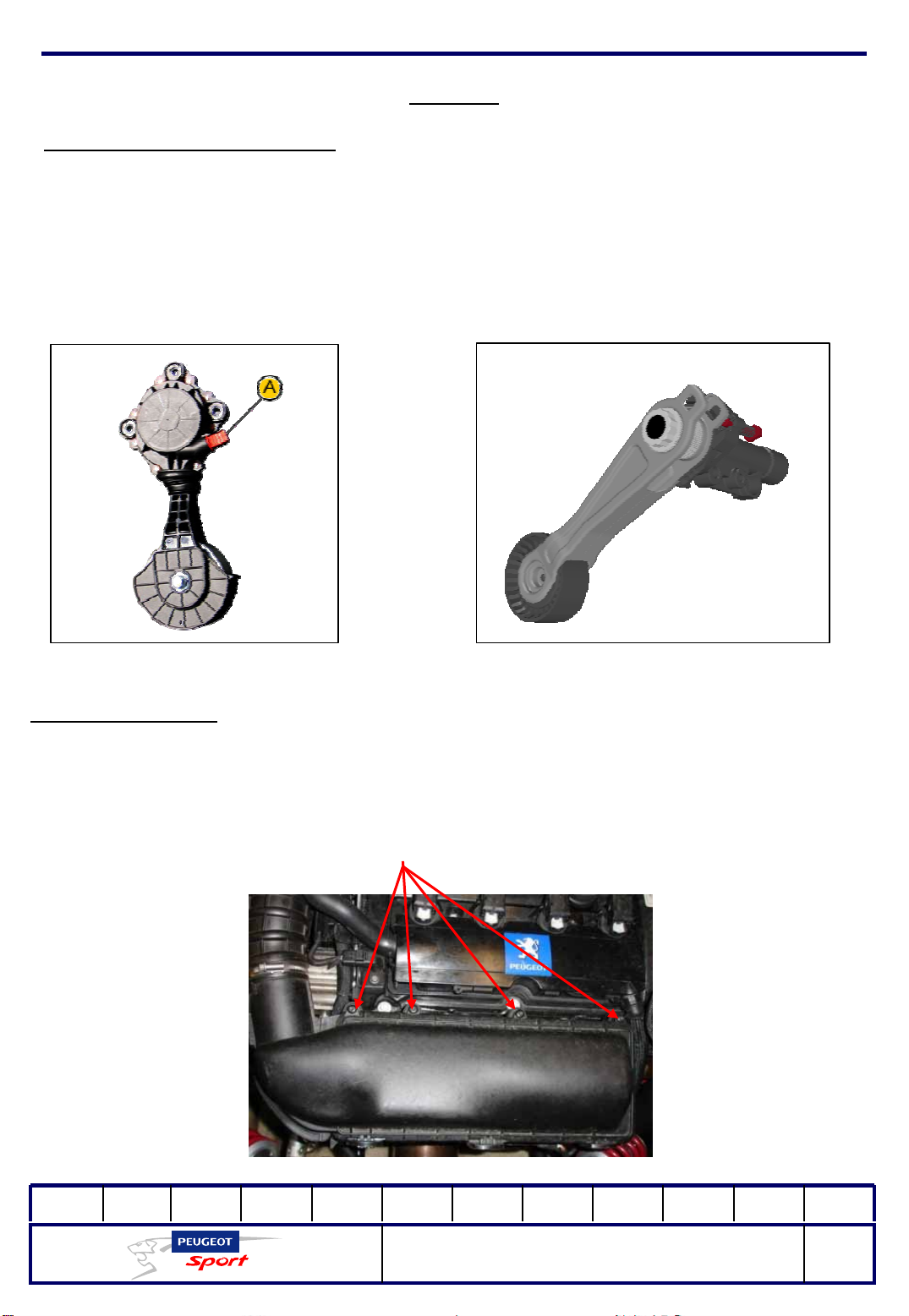
Replacing the accessory belt:
To dismantle the belt, use (A) to disengage the water pump drive roller.
A torsion bar integrated in the automatic tension regulator regulates the belt
tension. A pin (in red on the right-hand drawing) maintains the belt in the idle
position while the belt is put in place.
Changing the filter:
The air filter on 207 Spider is a GREEN.
To replace the air filter, unscrew the 4 torque-head screws from the cover of the air
tank and remove it; remove the filter and replace it with a new one; replace the
cover and the 4 screws.
01Ed. :
Retirer les 4
vis étoiles
207 Spider Technical Instructions
NOT 207 SPI-80
46
Page 48

Ce document est la propriété de Peugeot Sport et ne peut être reproduit ou communiqué sans autorisation.
This document is the property of Peugeot Sport and may not be copied o r circulated without permission .
Engine
Dismantling the power train unit:
Before commencing any dismantling operation, make sure that the engine
(especially the turbo-catalytic converter unit) has cooled sufficiently.
You must secure the vehicle on a vehicle lift or a tripod support so that it remains
stable before dismantling the engine.
Take apart the following parts of the car body:
- rear casing
-Extractor
Disconnect the engine housing, the wiring bundles connected to the engine and
the gearbox, the various power train sensors and probes (oil sensor, catalytic
converter probe, and so on).
Drain the water circuit and disconnect all the engine hoses.
Remove the wheels and dismantle the 2 rear hub carriers, the shock absorbers and
brake hoses.
Take out the transmissions from the tulip housings.
Disconnect the petrol intake pipe on the engine.
Dismantle the air intake pipe and the plastic connections connected to the turbo
exchanger.
Dismantle the exhaust pipe at the hose and take it out.
Disconnect the air intake coupling and the lugs and dismantle the solenoid valve
from the chassis.
Dismantle the cylinder at the two ends and remove it at the same time as the
solenoid valve (you do not have to take out the hoses).
Take out the clutch cable and the reverse cable.
Loosen the two attachment screws from the clutch housing on the anti-torque
cross member.
01Ed. :
207 Spider Technical Instructions
NOT 207 SPI-80
47
Page 49

Ce document est la propriété de Peugeot Sport et ne peut être reproduit ou communiqué sans autorisation.
This document is the property of Peugeot Sport and may not be copied o r circulated without permission .
Engine
Remove the screw located on the end of the cross member (on the rear cradle
side), the nut (on the cockpit side) and take out the cross member from the bottom.
From this point, you should suspend the engine on a hoist (max load of 250 kg)
Loosen the retaining screws on the gearbox positioning cylinders on the rear cradle.
Loosen the cylinder head mounting screws on the rear cradle. The power train is
disconnected from the chassis.
Using the hoist, take out the engine from the top by raising the right side of the
engine. Make sure that the car remains well balanced on the vehicle lift or the
tripod stand.
Reassembling the Power train unit:
Repeat the steps above, but in reverse.
Use a little grease when replacing all the fastenings, with the exception of the
screws for the power train cross member, for which you should use Loctite 248 or
similar.
Fill, drain and check the brake circuit and cooling circuit levels.
Fuel circuit:
The petrol tank is a flexible bladder (maximum capacity of 60 litres) that meets the
requirements of FIA standard FIA FT 3-1999, and an aluminium shell. In accordance
with the regulation, the tank is sealed with a cover made from a composite
material.
The validity date and the manufacturer's data are visible when the shell plate is
taken out (loosen the 4 M6 nuts).
01Ed. :
207 Spider Technical Instructions
NOT 207 SPI-80
48
Page 50
Ce document est la propriété de Peugeot Sport et ne peut être reproduit ou communiqué sans autorisation.
This document is the property of Peugeot Sport and may not be copied o r circulated without permission .
Engine
Filling the tank:
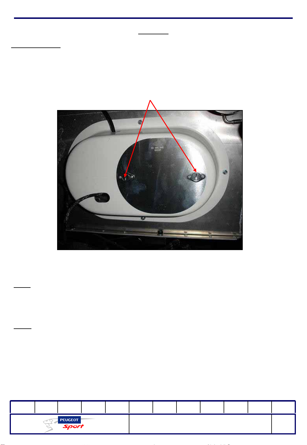
A STAUBLI connection on the top of the tank plate is used to fill the tank. It can be
accessed by removing the plate from the tank cover (attached with 2 Dzus).
Dzus à retirer
You can also fill the tank by unscrewing the plug next to the STAUBLI.
N.B.:
before you fill the tank (using the STAUBLI), the competition driver should make
sure to unscrew the plug to prevent pressure from mounting in the tank. The airing
device designed to drain the tank does not have a sufficient flow rate to exhaust the
air when filling the tank.
Note:
all the tank parts must be replaced after filling.
There is no specific pump for draining the petrol tank.
You must use the main petrol channel for this. Put the car on a flat surface (on level
on trestles). Disconnect the petrol hose at the engine to collect the fuel in an
appropriate container. Wait until the tank is empty. Afterwards, replace the petrol
hose.
01Ed. :
207 Spider Technical Instructions
NOT 207 SPI-80
49
Page 51
Ce document est la propriété de Peugeot Sport et ne peut être reproduit ou communiqué sans autorisation.
This document is the property of Peugeot Sport and may not be copied o r circulated without permission .
Gearbox
Presentation of the gearbox:
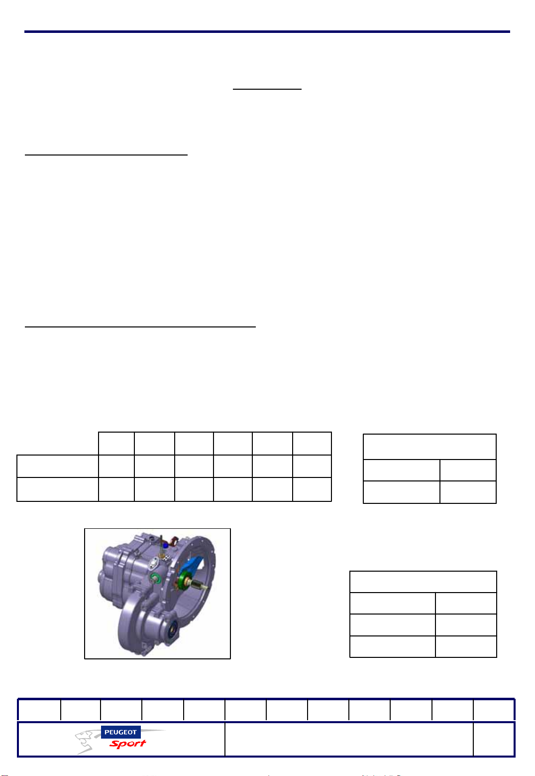
The SADEV ST75-14 sequential gearbox has 6 speeds plus reverse.
It weighs some 38.5 kg, without the reverse cable.
It is fitted with friction disk auto-lock and ramp clutch pressure plates.
It is assembled in special SADEV aluminium housing.
The clutch control is mechanical. It is supplied with the kit.
The reverse unlock cable is also supplied (length adjusted by the user), as is the filler
cap and the gear potentiometer.
Technical characteristics of the gearing:
st
1
nd
2
rd
3
th
4
th
5
th
6
272522201612Primary
262829323434Secondary
Cylindrical torque
15Primary
54Ring gear
Reverse
14Primary
32Back gears
38Secondary
01Ed. :
207 Spider Technical Instructions
NOT 207 SPI-80
50
Page 52
Ce document est la propriété de Peugeot Sport et ne peut être reproduit ou communiqué sans autorisation.
This document is the property of Peugeot Sport and may not be copied o r circulated without permission .
Gearbox
Technical characteristics of the auto-lock:
Friction disk auto-lock and ramp clutch pressure plates, asymmetrical operation on
acceleration and deceleration.
- Acceleration ramp rate = 45°
- Deceleration ramp rate = 80°
Preload new, cold = 8 Mr.DaN
NB. When the auto-lock is run in, the preload falls by about 15%.
NB. Measured cold (workshop), the preload is about 15% higher than when
measured warm.
Lubrication:
Capacity: 1.2 litres (does not correspond to the rear housing cap).
Viscosity qualityOil change frequency1st oil change
Total 80W140 same as
At each meetingAfter the first 50 km
206 RCC see Boutique
Peugeot Sport
Precautions:
It is strictly to put additives into the oil. The consequences arising will not be covered
under any circumstances.
In the event that there is additional oil in the gearbox, do not mix any other oil with
the one already in the gearbox.
01Ed. :
207 Spider Technical Instructions
NOT 207 SPI-80
51
Page 53
Ce document est la propriété de Peugeot Sport et ne peut être reproduit ou communiqué sans autorisation.
This document is the property of Peugeot Sport and may not be copied o r circulated without permission .
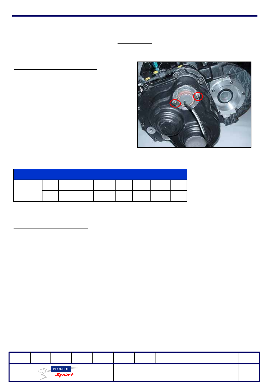
Adjusting the potentiometer:
The gearbox must be in neutral for
this adjustment.
Nominal value at neutral = 43
Loosen the two screws (red marker)
Turn the potentiometer until you
reach the correct value.
Gearbox
Gears
654321NoR
Value
11234191147105644322
Gear-change procedure:
The gear change system is pneumatic. Sufficient pressure is required for the system
to work.
For this, wait for the accumulator to fill to be able to use the system.
Going into 1
st
= declutch, press the release (black button), maintain the position
and press the Up paddle (on the right of the steering wheel).
st
Going into neutral = you must be in 1
Going into Reverse = you must be in 1
, press neutral (green button).
st,
pull the cable, press release (black button),
maintain the position and press rear (red button)
01Ed. :
207 Spider Technical Instructions
NOT 207 SPI-80
52
Page 54
Ce document est la propriété de Peugeot Sport et ne peut être reproduit ou communiqué sans autorisation.
This document is the property of Peugeot Sport and may not be copied o r circulated without permission .
Gearbox
Note:
the gear control system has a security device to avoid excess engine speed when
downshifting.
You cannot shift down to a lower gear if the estimated engine speed is within the
prohibited range.
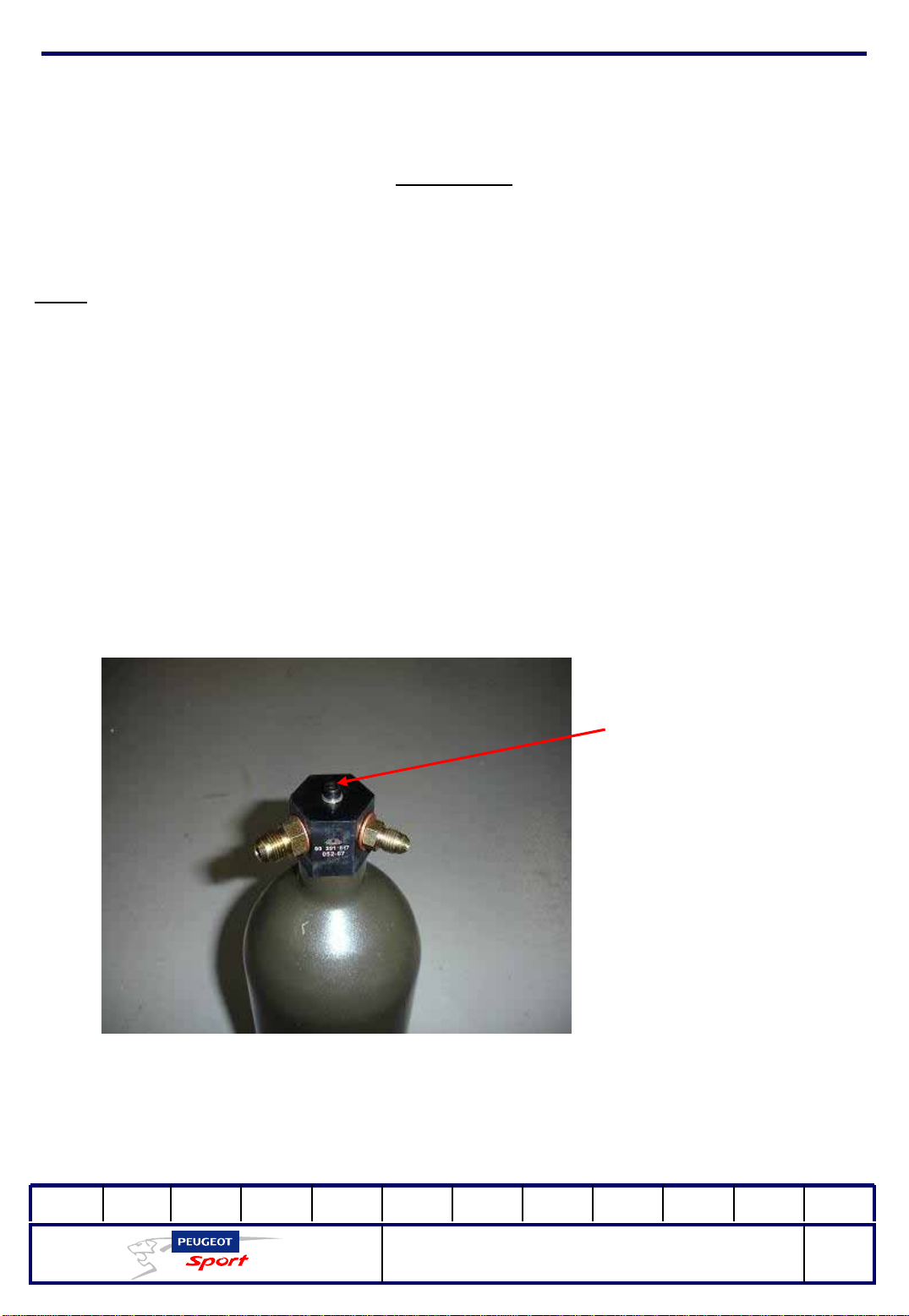
Remember to unscrew the bleeder screw under the cylinder to drain any water that
may have condensed inside, after each usage. We also recommend regularly
washing the compressor air filter.
Vis de purge
01Ed. :
207 Spider Technical Instructions
NOT 207 SPI-80
53
Page 55
Ce document est la propriété de Peugeot Sport et ne peut être reproduit ou communiqué sans autorisation.
This document is the property of Peugeot Sport and may not be copied o r circulated without permission .
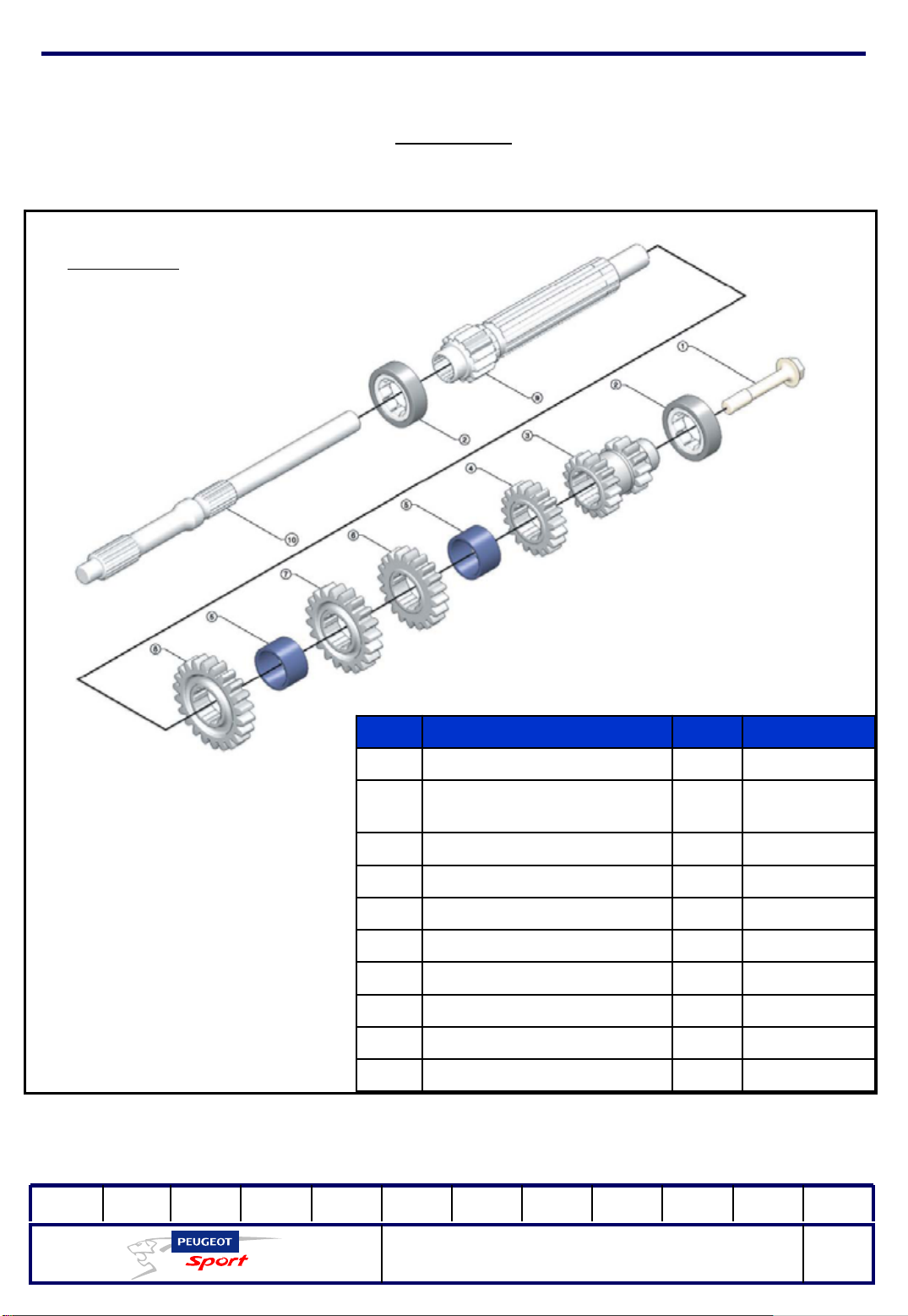
Primary line
Gearbox
C. TorqueGlue Description Ref
1
01Ed. :
Transmission input shaft
screw
NU304 roller bearing2
1-2 gear3
3rd gear4
Shaft spacer5
4th gear6
5th gear7
6th gear8
Transmission input shaft9
Clutch shaft10
10.0 m.daN270
207 Spider Technical Instructions
NOT 207 SPI-80
54
Page 56
Ce document est la propriété de Peugeot Sport et ne peut être reproduit ou communiqué sans autorisation.
This document is the property of Peugeot Sport and may not be copied o r circulated without permission .
Gearbox
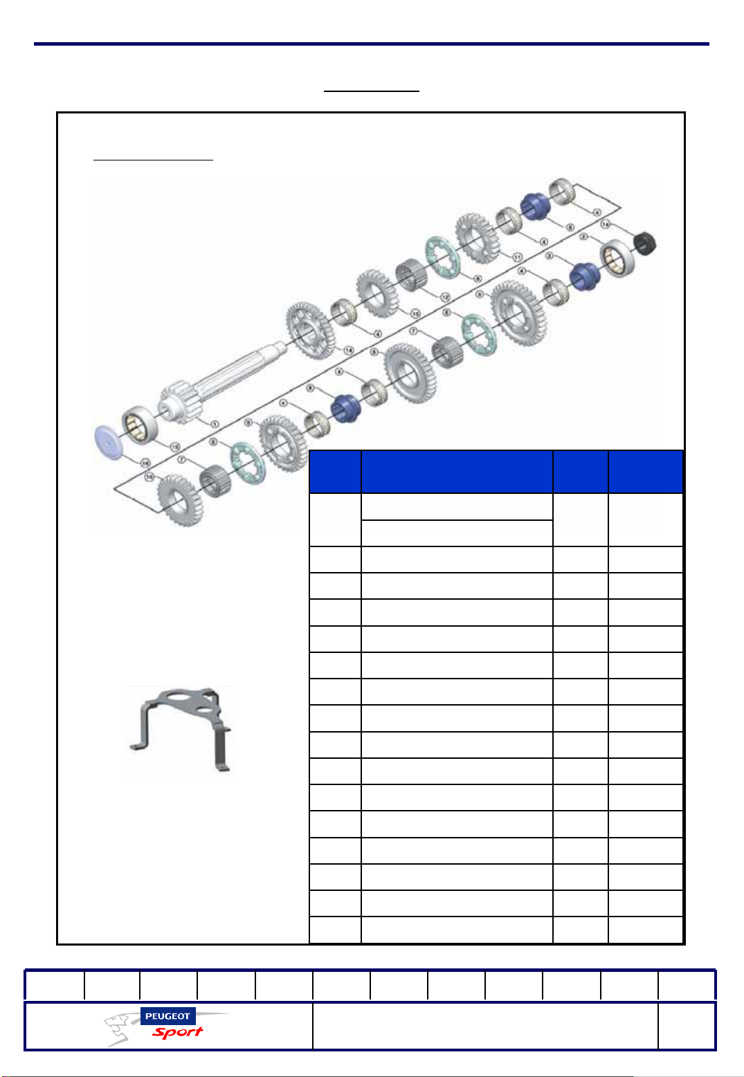
Secondary line
Fitted secondary shaft
1
A (secondary nut)
NU206 bearing2
1st gear shouldered
3
bushing
Needle bearing4
1-2 gear5
Sliding sleeve6
Sliding sleeve holder7
Shouldered bushing8
3rd gear9
4th gear10
5th gear11
Sliding sleeve holder 5/612
6th gear13
Glue Description Ref
648
C.
Torque
20.0
m.daN
REV wheel14
NJ2206 bearing15
Cannula16
01Ed. :
207 Spider Technical Instructions
NOT 207 SPI-80
55
Page 57
Ce document est la propriété de Peugeot Sport et ne peut être reproduit ou communiqué sans autorisation.
This document is the property of Peugeot Sport and may not be copied o r circulated without permission .
Gearbox
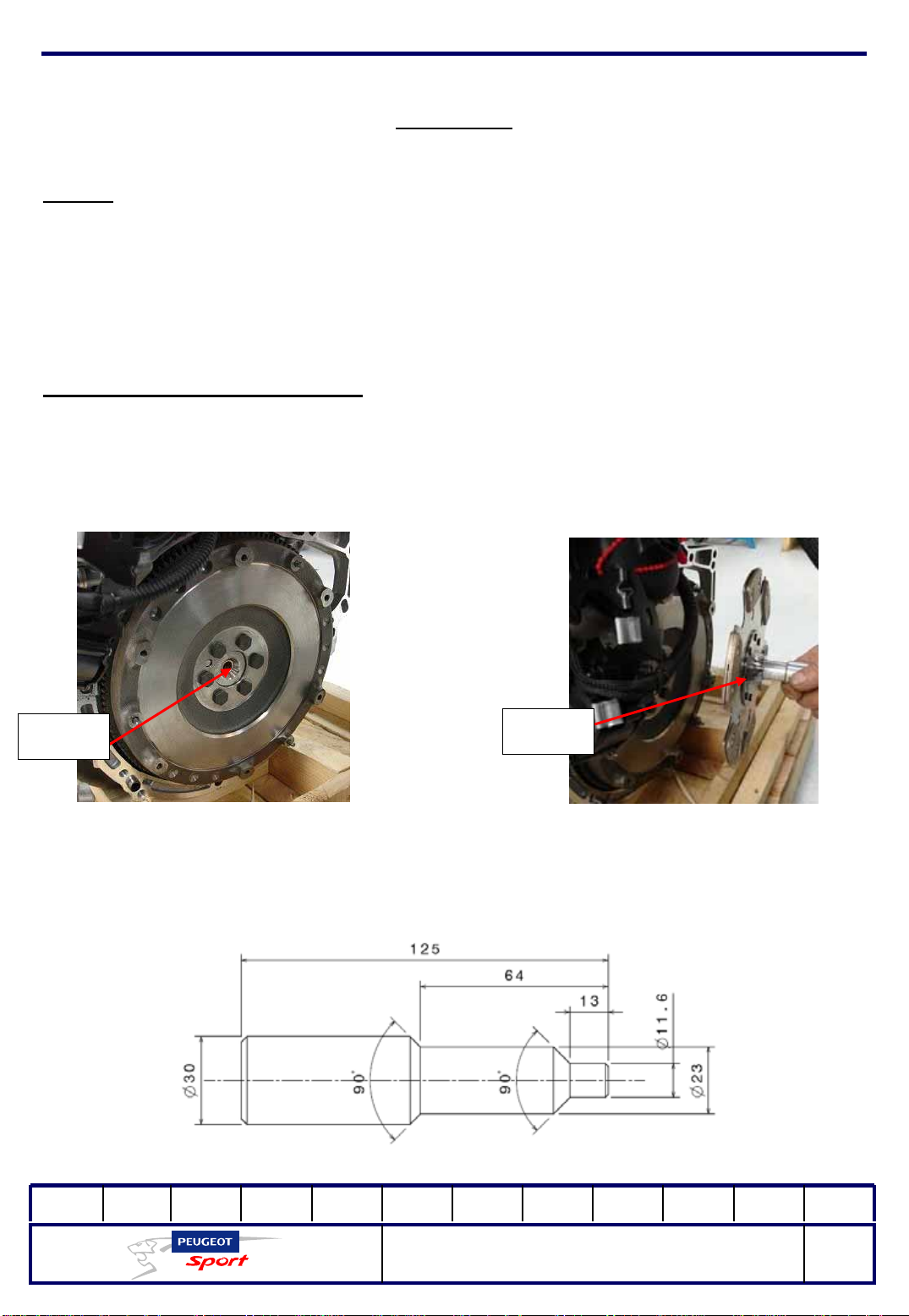
Clutch:
Dry, cerametallic single-disk clutch
Standard diaphragm push-type mechanism.
Manual adjustment cable control.
Stop.
Tightening torque for the mechanism's screws: 2m.daN
Procedure for replacing the disk:
Dismantle the 6 screws located on the clutch mechanism and then take out the
worn disk. Make sure that the ring of the clutch shaft nose remains in its housing
Bague
Déport
Place the clutch disk on the centring pin (see plan below), following the offset
direction
0Ed. :
207 Spider Technical Instructions
NOT 207 SPI-80
56
Page 58
Ce document est la propriété de Peugeot Sport et ne peut être reproduit ou communiqué sans autorisation.
This document is the property of Peugeot Sport and may not be copied o r circulated without permission .
Gearbox
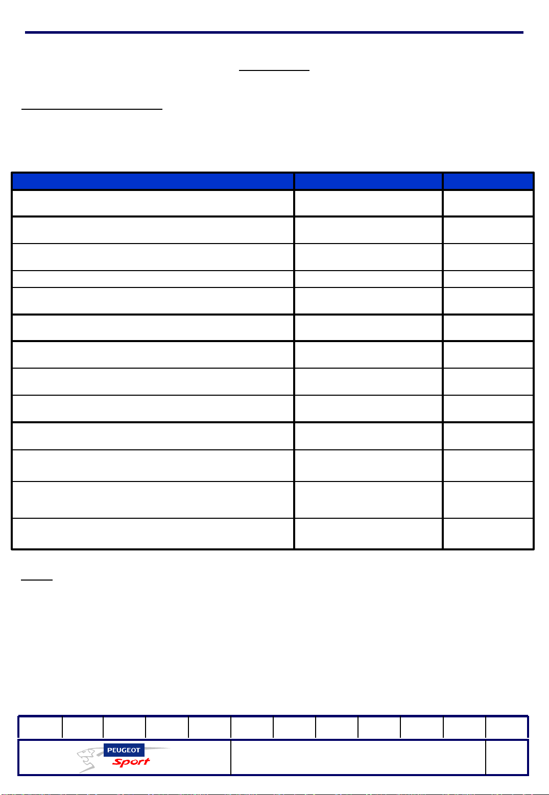
Maintenance schedule:
This is given according to the number of kilometres run by the equipment in racing
conditions.
Frequency ActionItem
ReplaceClutch shaft
ReplaceDifferential bearings
ReplaceInput and secondary shaft bearings
Each season
~2,200 km
Each season
~2,200 km
Each season
~2,200 km
Each oil changeReplaceDrain plug seals
Each oil changeClean Drain plugs
Auto-lock preload
CHECK GEARBOX and Service booklet (seals, safety fastenings,
etc.)
Note:
Service packs are available, product codes:
ReplaceControl springs (recoil, indexing, tappet)
Check and ensure conformity if
required
Check and repair if requiredCHECK GEARBOX: dismantle/reassemble
Dismantle, reassemble,
penetrant inspection of parts
ReplaceClutch release bearing
Each season
~2,200 km
Each overhaulReplaceShaft screws (input and secondary shafts)
Each overhaulReplaceTorque ring screw
Each overhaulReplaceDifferential housing cover screw
Every 2nd meeting
~550km
Mid-season
~1,100km
Each season
~2,200 km
Mid-season
~1,100km
- Service pack: KITREVST7514PS2 (safety fastenings, seal fastenings)
- Bearing pack: KITRLTST7514PS1
This schedule is subject to change over the lifecycle of the ST75-14 SPIDER 207
product.
01Ed. :
207 Spider Technical Instructions
NOT 207 SPI-80
57
Page 59
Ce document est la propriété de Peugeot Sport et ne peut être reproduit ou communiqué sans autorisation.
This document is the property of Peugeot Sport and may not be copied o r circulated without permission .
Running gear
Tyres:
The tyres are MICHELIN.
Slick type S8B
P2C rain tyre
Front dimension 21/65-18
Rear dimension 21/65-18
Cold pressure (as an indication only):
-1.8 Bar in front
-1.7 Bar in back
8 x 18" front wheel rim
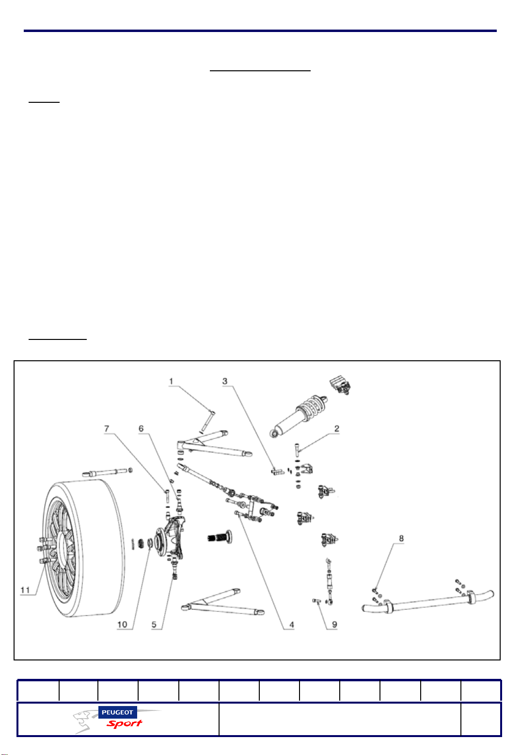
Front axle:
01Ed. :
207 Spider Technical Instructions
NOT 207 SPI-80
58
Page 60
Ce document est la propriété de Peugeot Sport et ne peut être reproduit ou communiqué sans autorisation.
This document is the property of Peugeot Sport and may not be copied o r circulated without permission .
Running gear
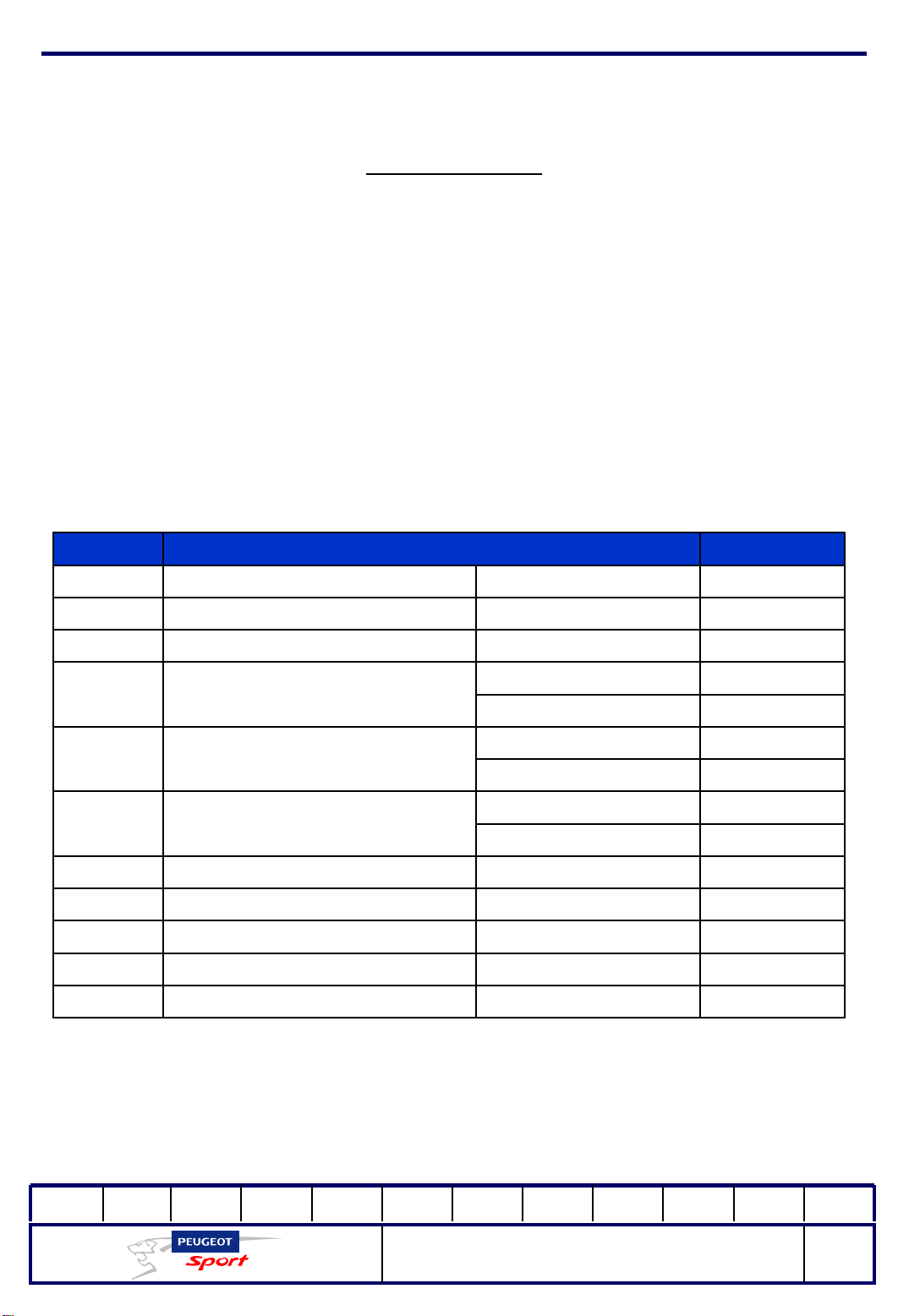
The front axle consists of two combined spring-shock absorber double-wishbone
suspensions.
It features an anti roll bar made from steel tubing, 25x1.5 mm section Ø mounted on
the front cradle on bearings.
C. TORQUEDESCRIPTIONNUMBER
1
5
6
7
8
9
Fix the connecting rod onto the
upper triangle
Fit the parts onto the rocker arm4
Fit the lower triangle onto the hub
carrier
Fit the upper tr iangle onto th e hu b
carrier
Fit the connecting rod onto the
hub carrier
Fit the rear cradle bearing onto the
chassis
Fit the connecting rods onto the
rear cradle
Fit the wheel on the hub11
M12 wheel mounting
screw
7.5 m.daNM10x90 CHC screw
7.5 m.daNM10x50 CHC screwFit the triangle onto the clevis2
3.5 m.daNM8x40 CHC screwFit the clevis onto the cradle3
3.5 m.daNM8x60 CHC screw
7.5 m.daNM10x68 CHC screw
16 m.daNM16 hub carrier spindle
7.5 m.daNM10 brake nut
16 m.daNM14 Hub carrier spindle
7.5 m.daNM10 brake nut
3.5 m.daNCHC M8x55 screw
3.5 m.daNCHC M8x50 screw
3.5 m.daNCHC M8x30 screw
34.5 m.daNM24 transmission nutFit the spindle on the hub10
13 m.daN
01Ed. :
207 Spider Technical Instructions
NOT 207 SPI-80
59
Page 61
Ce document est la propriété de Peugeot Sport et ne peut être reproduit ou communiqué sans autorisation.
This document is the property of Peugeot Sport and may not be copied o r circulated without permission .
Running gear
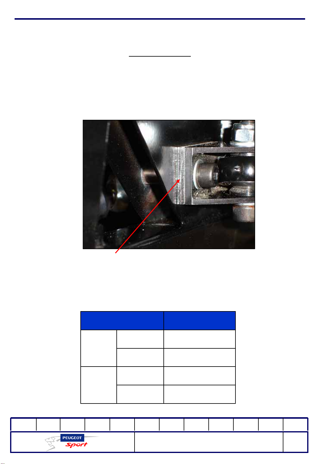
The camber specified by the regulation is obtained by adding spacers behind the
upper and lower suspension clevis.
Cales de chape de suspension
These are spacers, 2mm thick, distributed as shown in the table below.
Number of spacersPosition of the clevis
1Upper
Front
2Lower
2Upper
Rear
3Lower
01Ed. :
207 Spider Technical Instructions
NOT 207 SPI-80
60
Page 62
Ce document est la propriété de Peugeot Sport et ne peut être reproduit ou communiqué sans autorisation.
This document is the property of Peugeot Sport and may not be copied o r circulated without permission .
Running gear
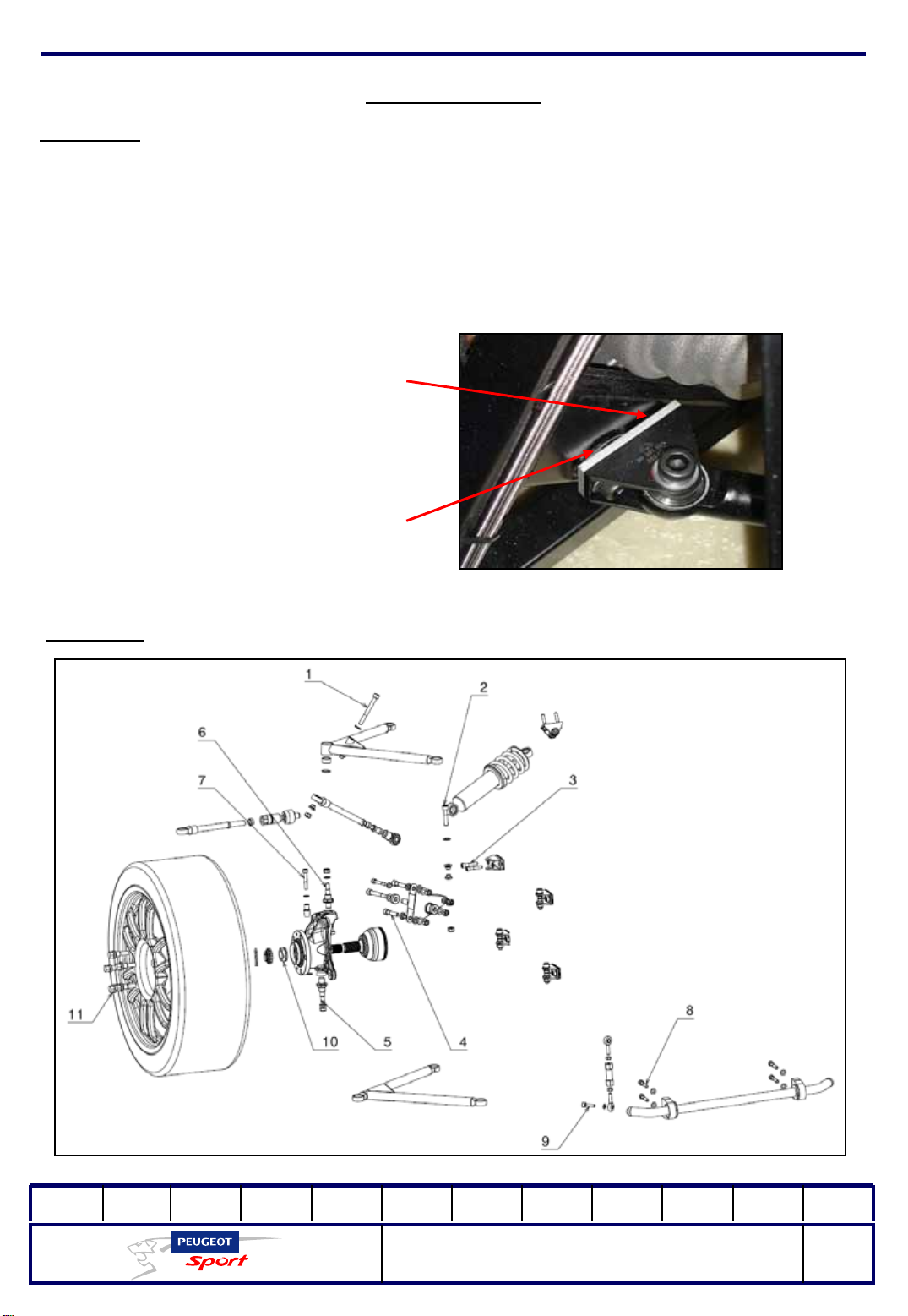
Important:
in view of the 2mm extra thickness behind the front fastening point of the rear lower
left-hand triangle, insert a set ring (90,391,942), but only two camber angle spacers.
For more information on the front axle assembly parts, please refer to the spare parts
catalogue.
90 391 942 CALE GOUSSET
AR G
Rear axle:
Surépaisseur sur
châssis
01Ed. :
207 Spider Technical Instructions
NOT 207 SPI-80
61
Page 63
Ce document est la propriété de Peugeot Sport et ne peut être reproduit ou communiqué sans autorisation.
This document is the property of Peugeot Sport and may not be copied o r circulated without permission .
Running gear
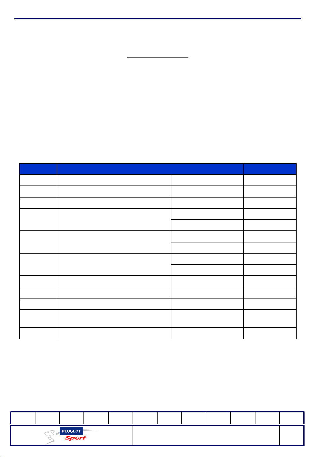
For the most part, the rear axle assemble consists of the same parts as the front.
However, the clamp connecting rod is longer than the steering tie rod and the anti roll bar section is not the same as in the front: Ø20x1.5mm.
C. TORQUEDESCRIPTIONNUMBER
1
Fix the connecting rod onto the
upper triangle
7.5 m.daNM10x90 CHC screw
7.5 m.daNM10x50 CHC screwFit the triangle onto the clevis2
3.5 m.daNM8x40 CHC screwFit the clevis onto the cradle3
Fit the parts onto the rocker arm4
5
6
7
8
9
Fit the lower triangle onto the hub
carrier
Fit the upper tr iangle onto th e hu b
carrier
Fit the connecting rod onto the hub
carrier
Fit the rear cradle bearing onto the
chassis
Fit the connecting rods onto the rear
cradle
Fit the wheel on the hub11
M16 hub carrier
spindle
M14 Hub carrier
spindle
M12 wheel mounting
screw
3.5 m.daNM8x60 CHC screw
7.5 m.daNM10x68 CHC screw
16 m.daN
7.5 m.daNM10 brake nut
16 m.daN
7.5 m.daNM10 brake nut
3.5 m.daNCHC M8x55 screw
3.5 m.daNCHC M8x50 screw
3.5 m.daNCHC M8x30 screw
34.5 m.daNM24 transmission nutFit the spindle on the hub10
13 m.daN
01Ed. :
207 Spider Technical Instructions
NOT 207 SPI-80
62
Page 64
Ce document est la propriété de Peugeot Sport et ne peut être reproduit ou communiqué sans autorisation.
This document is the property of Peugeot Sport and may not be copied o r circulated without permission .
Running gear
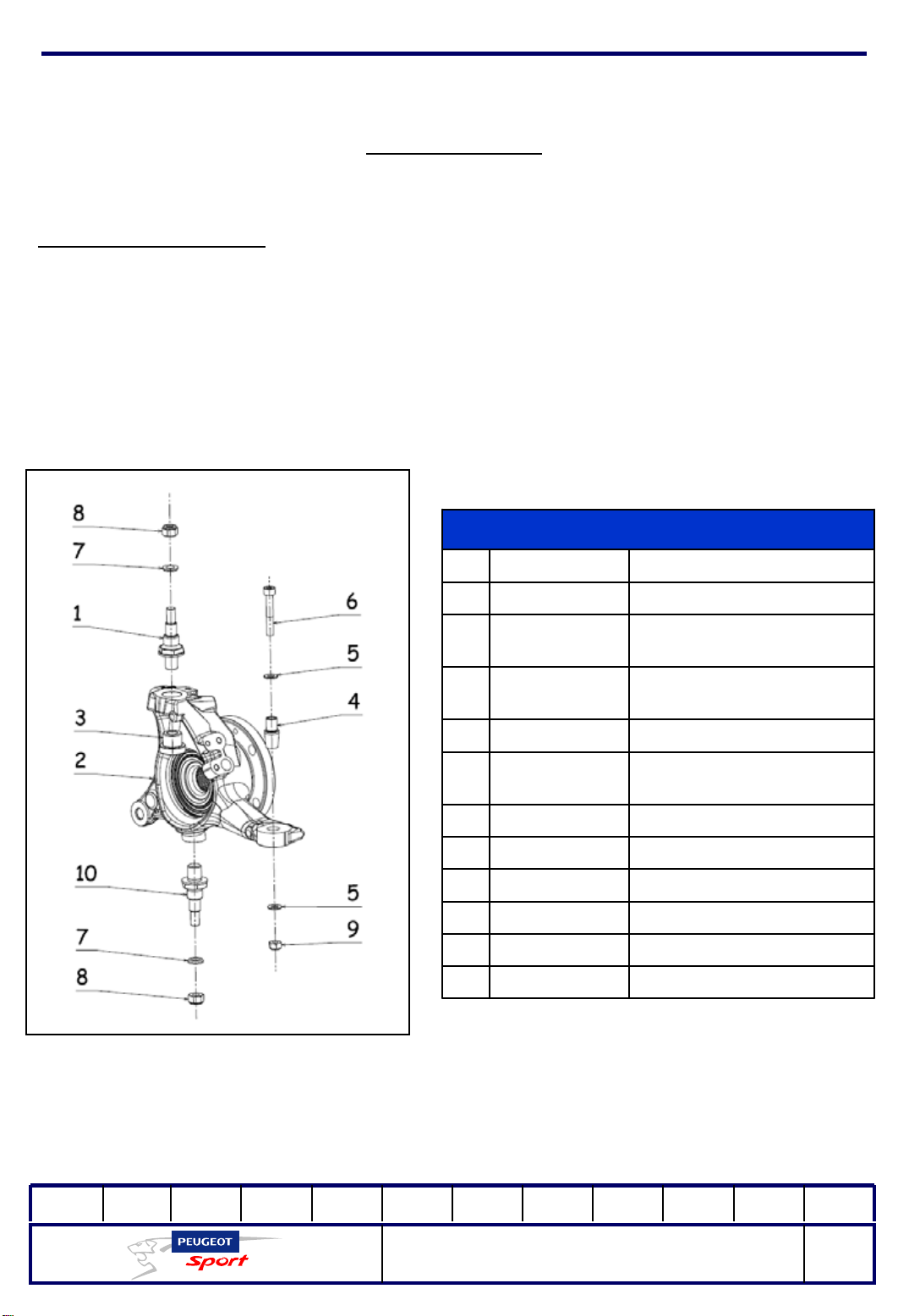
Assembled hub carrier:
The front and rear hub carriers are identical. Naturally, the right and left sides are
asymmetrical.
The upper and lower pins are differentiated by their threaded parts.
The gun (3) must be assembled after you cool it in the freezer and then heat the hub
carrier upper bore.
No
.
Hub carrier unit
DescriptionRef
HUB CARRIER SPINDLE903912878D1
903912888C2
903913428C2
903913088C4
903918228A7
903919118A10
FACTORY D 407 HUB
CARRIER ASSEMBLED
FACTORY G 407 HUB
CARRIER ASSEMBLED
HUB CARRIER GUN903912898C3
HUB CARRIER SHAFT
CONNECTING ROD
8x16 FLAT WASHER903915148A5
M8x55 CHC screw903940068A6
HUB CARRIER SHAFT
SPACER
NYLSTOP M10 NUT903910178A8
NYLSTOP M8 NUT903917068A9
M16 HUB CARRIER
SPINDLE
01Ed. :
207 Spider Technical Instructions
NOT 207 SPI-80
63
Page 65
Ce document est la propriété de Peugeot Sport et ne peut être reproduit ou communiqué sans autorisation.
This document is the property of Peugeot Sport and may not be copied o r circulated without permission .
Running gear
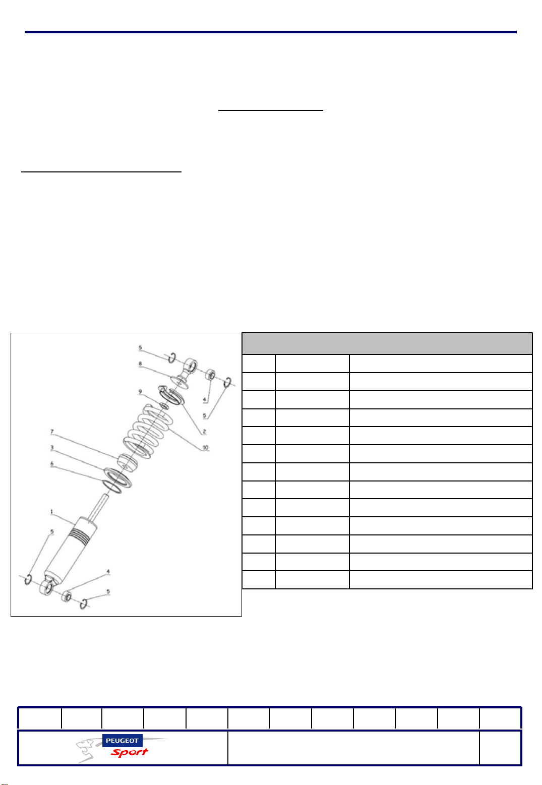
Shock absorber and spring:
The shock absorbers used on 207 Spider are not adjustable, except for the spring
preload.
This can be adjusted through the 5 grooves on the shock absorber body.
The front and rear shock absorbers are different.
Assembled shock absorber
DescriptionRefNo.
903918138A1
903918068A1
903918108A5
903918118A6
KONI 30 SERIES REAR SHOCK
KONI 30 SERIES FRONT SHOCK
SHOCK ABSORBER UPPER CUP903918078A2
SHOCK ABSORBER LOWER CUP903918088A3
SHOCK ABSORBER BALL JOINT 903918098A4
SHOCK ABSORBER TYPE 1 RETAINING
SHOCK ABSORBER TYPE 2 RETAINING
SHOCK ABSORBER BUMPER903917048A7
SHOCK ABSORBER HEAD903941358A8
SHOCK ABSORBER LOCK NUT903941368A9
ABSORBER
ABSORBER
RING
RING
REAR SPRING903918038B10
FRONT SPRING903918028B10
01Ed. :
207 Spider Technical Instructions
NOT 207 SPI-80
64
Page 66
Ce document est la propriété de Peugeot Sport et ne peut être reproduit ou communiqué sans autorisation.
This document is the property of Peugeot Sport and may not be copied o r circulated without permission .
Running gear
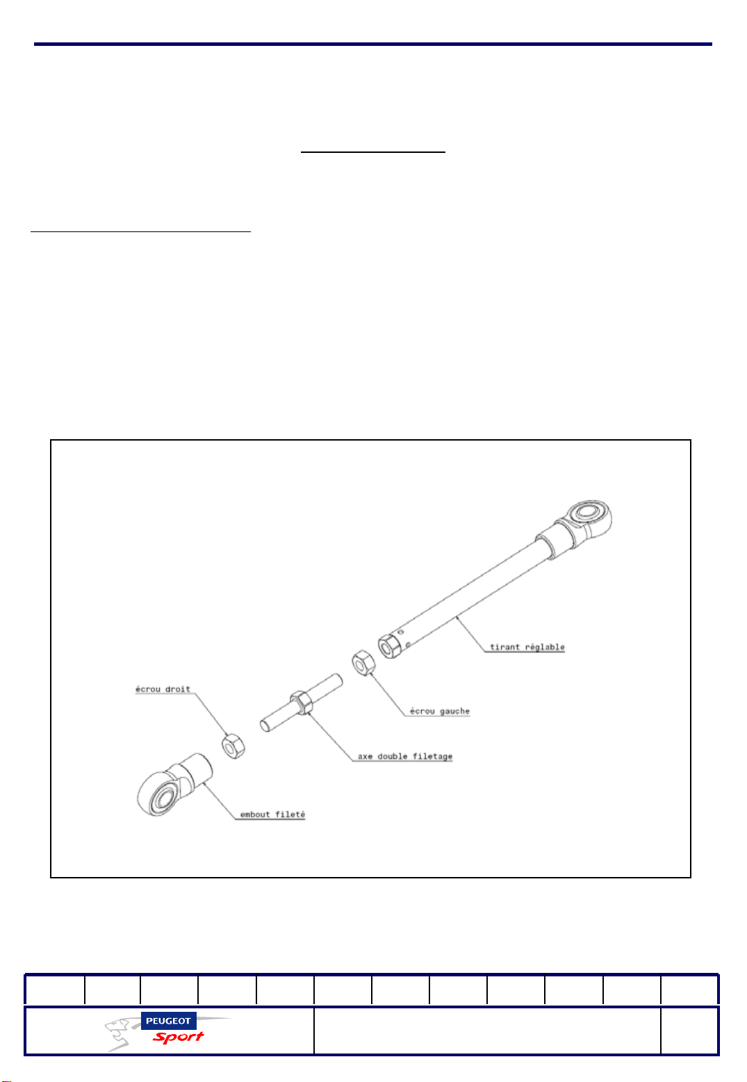
Adjusting the body heights:
207 Spider features adjustable suspension tie rods to adjust the height of the body.
Each tie rod consists of a double threaded pin fastened to the two parts of the tie rod
and locked in position with two nuts (one right-threaded and the other leftthreaded).
01Ed. :
207 Spider Technical Instructions
NOT 207 SPI-80
65
Page 67
Ce document est la propriété de Peugeot Sport et ne peut être reproduit ou communiqué sans autorisation.
This document is the property of Peugeot Sport and may not be copied o r circulated without permission .
Steering
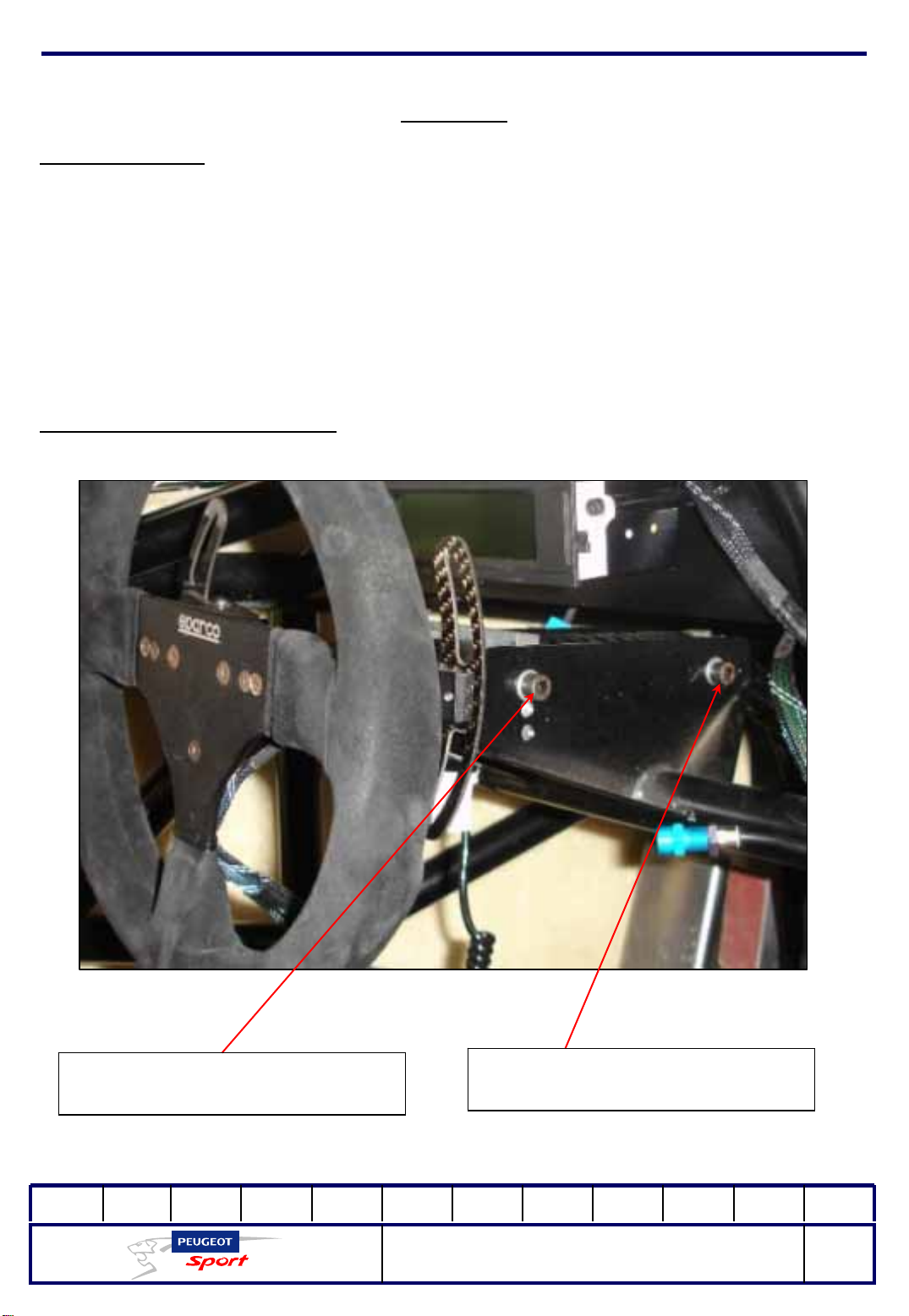
Steering column:
The 207 Spider steering column includes a part engineered to crumple in the event
of frontal impact (FIA approved).
The Quick release system means the steering wheel can be released simply by
pressing down on the disk behind the wheel.
The steering wheel wiring can be quickly disconnected from the chassis wiring
bundle.
A good adjustment range is ensured by sliding tilt bearing on the column tube and
the various holes drilled in the steering column fastening plates.
Adjusting the steering column:
Steering wheel height
adjustment
01Ed. :
Steering wheel height
adjustment
207 Spider Technical Instructions
NOT 207 SPI-80
66
Page 68
Ce document est la propriété de Peugeot Sport et ne peut être reproduit ou communiqué sans autorisation.
This document is the property of Peugeot Sport and may not be copied o r circulated without permission .
Department
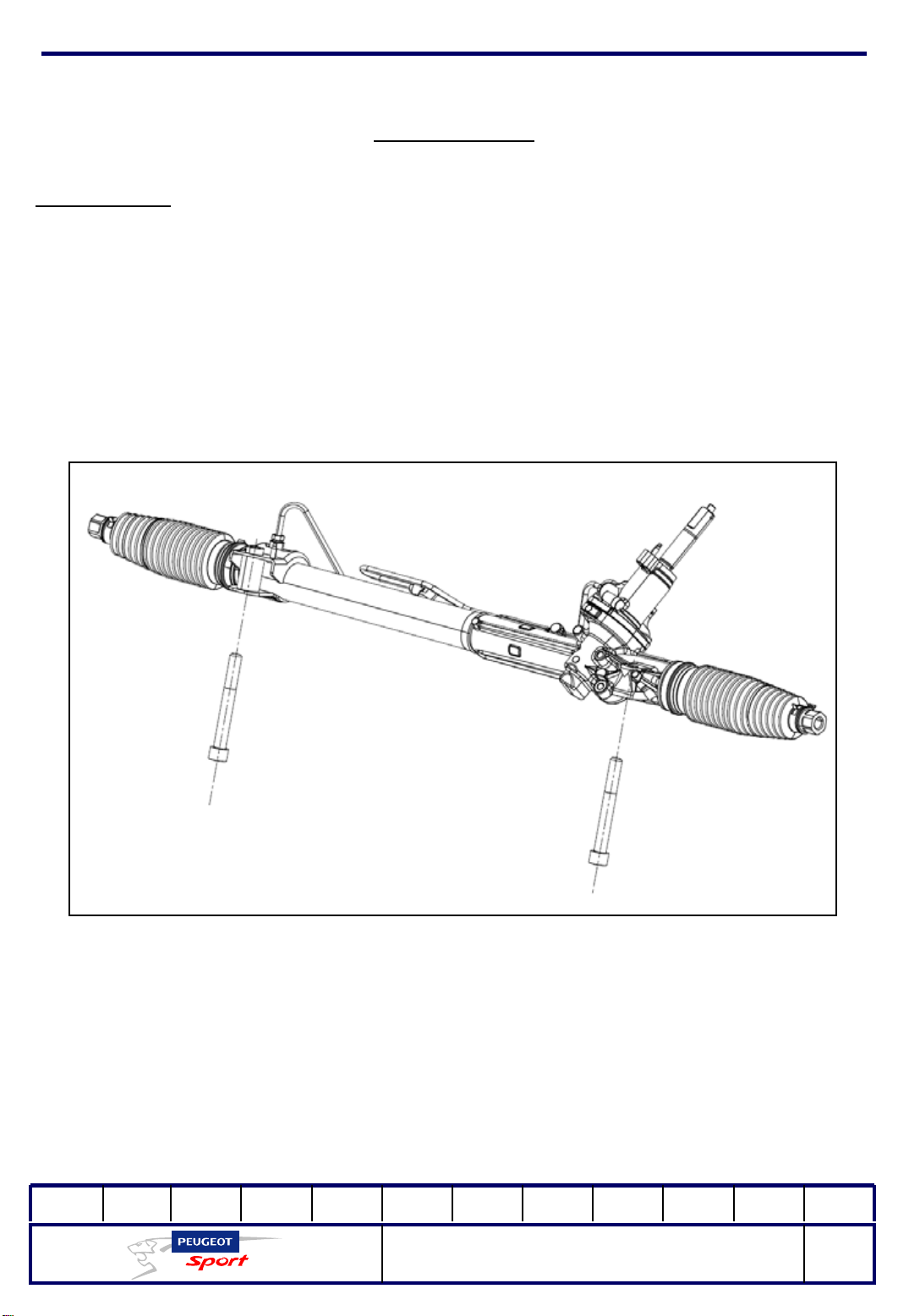
Steering rack:
The steering rack is fastened with 2 M14 x 110 screws to the front cradle (tightening
torque: 20 m.daN).
It is coupled to an electric pump by two high-pressure pipes with crimped ends.
Under no circumstances should these ends be dismantled.
Two nylon steering stops prevent any contact between the suspension and the wheel
rim when cornering.
01Ed. :
207 Spider Technical Instructions
NOT 207 SPI-80
67
Page 69
Ce document est la propriété de Peugeot Sport et ne peut être reproduit ou communiqué sans autorisation.
This document is the property of Peugeot Sport and may not be copied o r circulated without permission .
Brakes
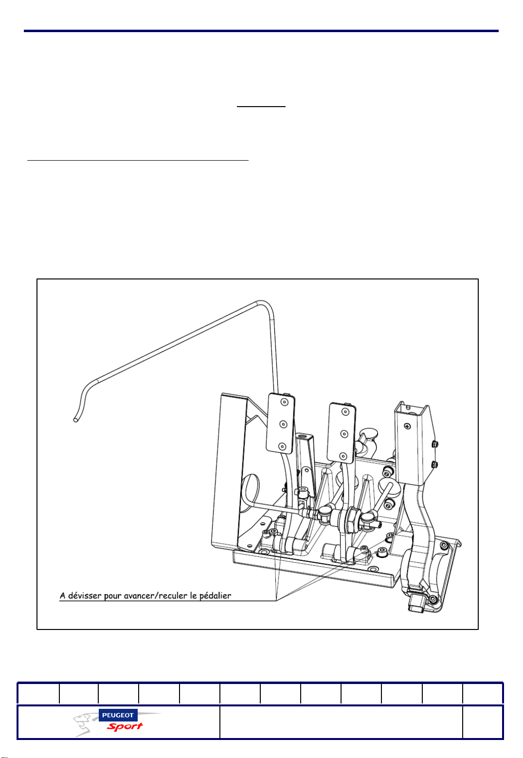
Adjusting the position of the pedal unit:
The position of the pedal unit can be adjusted lengthwise over a course of 40mm,
step by step.
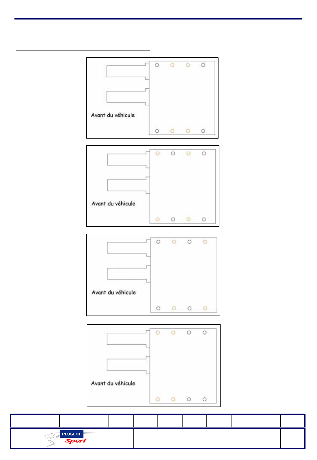
To do this, loosen the 4 M8 fastening screws on the pedal unit and move it
forwards or backwards to the desired position. Replace the screws in the holes
shown on the diagram (marked in orange) and tighten.
01Ed. :
207 Spider Technical Instructions
NOT 207 SPI-80
68
Page 70
Ce document est la propriété de Peugeot Sport et ne peut être reproduit ou communiqué sans autorisation.
This document is the property of Peugeot Sport and may not be copied o r circulated without permission .
Brakes
Adjusting the position of the pedal unit:
Position x = 0 mm
Position x = 40 mm
Position x = 80 mm
Position x = 120 mm
01Ed. :
207 Spider Technical Instructions
NOT 207 SPI-80
69
Page 71
Ce document est la propriété de Peugeot Sport et ne peut être reproduit ou communiqué sans autorisation.
This document is the property of Peugeot Sport and may not be copied o r circulated without permission .
Brakes
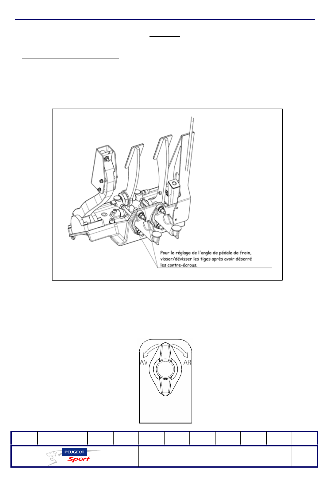
Adjusting the pedal unit tilt:
The brake pedal angle is adjustable b y tightening or loosening the stems of the
master cylinder.
However, you must be sure to adjust both stems at the same time.
Adjusting the balance of the front and rear brakes:
Use the star wheel on the floor to the left of the driver to adjust the balance of
the front and rear brakes.
01Ed. :
207 Spider Technical Instructions
NOT 207 SPI-80
70
Page 72
Ce document est la propriété de Peugeot Sport et ne peut être reproduit ou communiqué sans autorisation.
This document is the property of Peugeot Sport and may not be copied o r circulated without permission .
Brakes
Characteristics:
Front and Rear disk: ventilated, Ø283 mm, 26 mm thick
Front and rear callipers: monopiston Ø28.5 mm
Carbone Lorraine brake pads: 90 391 819 8A
Master brake cylinders: 2x GIRLING Ø3/4" (19.05mm)
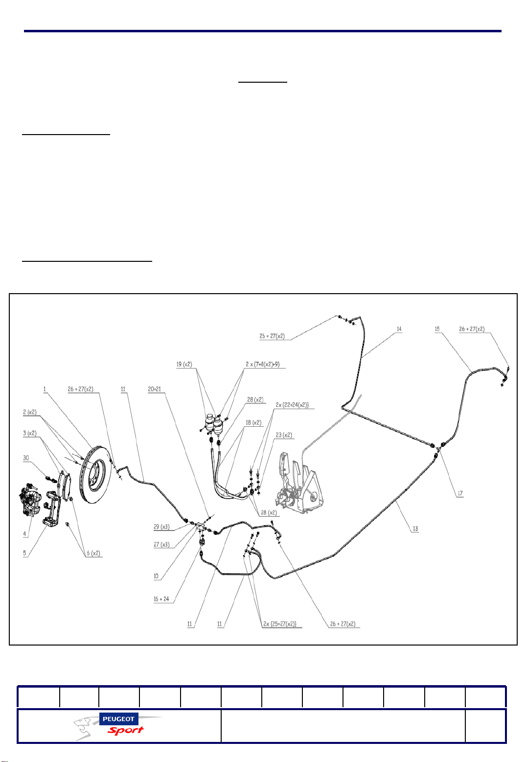
Brake system diagram:
01Ed. :
207 Spider Technical Instructions
NOT 207 SPI-80
71
Page 73
Ce document est la propriété de Peugeot Sport et ne peut être reproduit ou communiqué sans autorisation.
This document is the property of Peugeot Sport and may not be copied o r circulated without permission .
Brakes
Components of the brake circuit
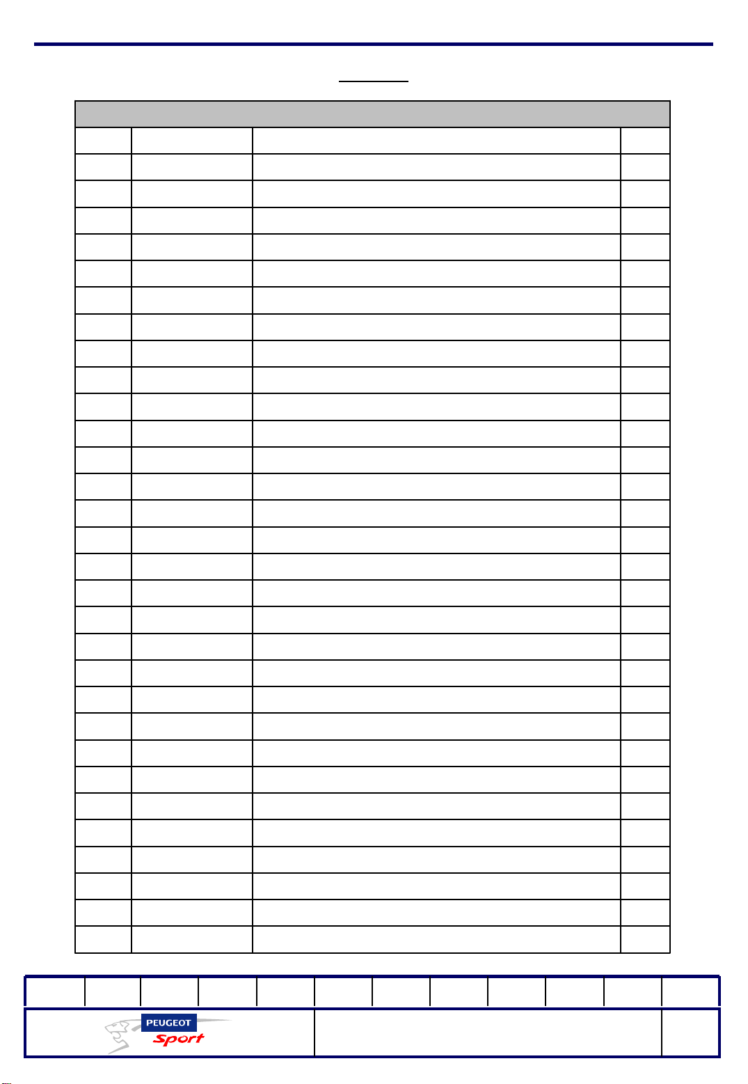
QtyPartReferenceNo.
4BRAKE DISK (sold in pairs)4246P71
8M6 x 16 ISO 10642 COUNTERSUNK HEAD SCREWS903918338A2
8BRAKE PADS903918198A3
2BRAKE CALLIPER (RIGHT)4401H24
BRAKE CALLIPER (LEFT)4401H34
2
4CALLIPER CLEVIS 4404865
8CALLIPER ATTACHMENT SCREW4405386
2NYLSTOP M6 ISO 10511 NUT903917748A7
46X12 WASHER903918378A8
2M6X10 ISO 4762 SCREW903918368A9
1TE FOR FRONT BRAKE CIRCUIT903919188A10
3FRONT CALLIPER HOSE903940278A11
1REAR TE POWER HOSE903940298A13
1REAR RH CALLIPER HOSE903940308A14
1REAR LH CALLIPER HOSE903940318A15
1STOP CONTACTOR903940648A16
1TE DASH 3903940698A17
2MASTER CYLINDER CONTAINER HOSE903940708A18
2BRAKE FLUID TANK903919488A19
1M5x30 ISO 4762 CHC SCREW903940588A 20
15x10 FLAT WASHER903918498A 21
2BANJO 7-16 UNF SCREW903940718A22
2BANJO UNION 903940728A23
57-16 COPPER SEAL903940738A24
2BANJO 3-8 UNF SCREW903940748A25
4BANJO M10x100 SCREW903940758A26
15DIAM 10 COPPER SEAL903940768A27
4COLLAR903940808A28
3ADAPTER903940898A29
8CLIP903941398A30
01Ed. :
207 Spider Technical Instructions
NOT 207 SPI-80
72
Page 74

Ce document est la propriété de Peugeot Sport et ne peut être reproduit ou communiqué sans autorisation.
This document is the property of Peugeot Sport and may not be copied o r circulated without permission .
Brakes
Draining the braking system:
Check that all the hoses in the cu circuit are correctly connected, then loosen the 4
bleeder screws. You could connect a recipient to collect the excess brake fluid
(a dedicated recipient) of each drain for all operations.
Fill the circuit until the liquid comes out of each calliper. As soon as the circuit is filled,
tighten the bleeder screws and press the brake pedal several times.
Keeping your foot on the brake, loosen one of the bleeder screws to release the air
in each calliper and press the pedal down to the limit. Repeat twice or three
times for each calliper.
Make sure that the container is always full and that the pedal becomes "hard".
Top up the level when you have drained the circuit.
Important:
Under no circumstances should the crimped ends be dismantled.
Using brake force distribution:
Use the lever on the floor to the driver's left to distribute the brake force to the front
or rear of the vehicle. As indicated on the notes on the base, to increase the
brake force on the front, turn the lever to the left. Turn it to the right to increase
the brake force to the rear.
01Ed. :
207 Spider Technical Instructions
NOT 207 SPI-80
73
Page 75
Ce document est la propriété de Peugeot Sport et ne peut être reproduit ou communiqué sans autorisation.
This document is the property of Peugeot Sport and may not be copied o r circulated without permission .
Roadholding
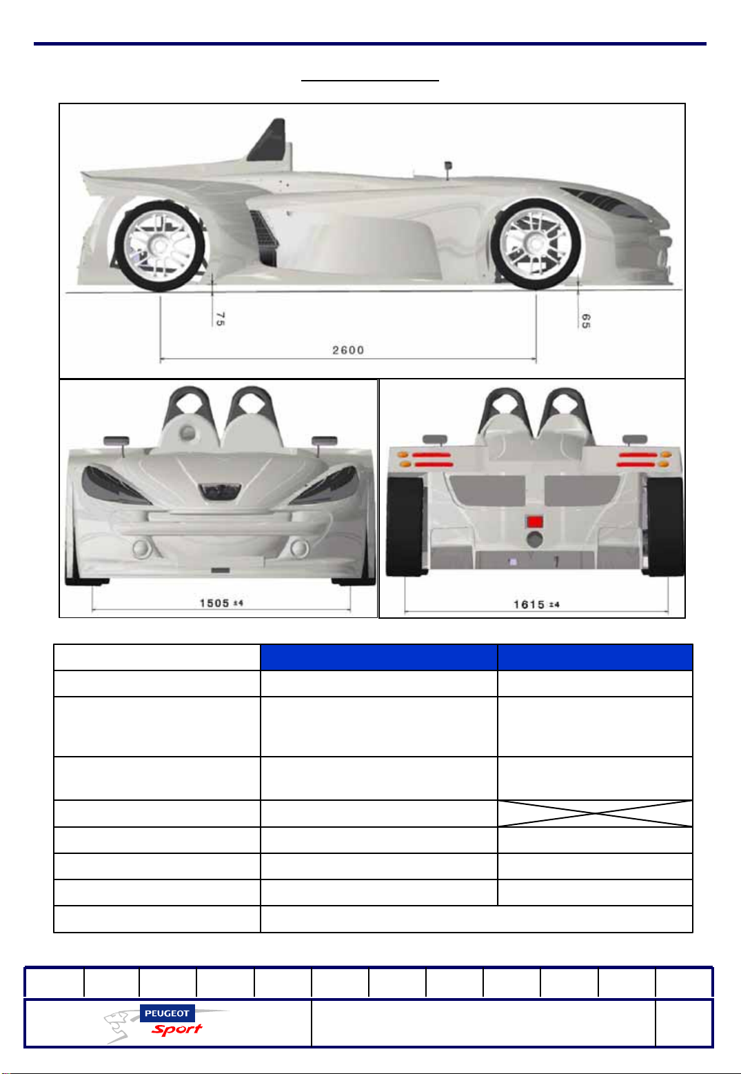
ALIGNMENT
COUNTER CAMBER ANGLE
01Ed. :
2 - 3 mm opening at the wheel
rim/wheel
(recommended)
Upper triangle: 1 spacer
Lower triangle: 2 spacers
Not adjustableCASTER ANGLE
2,600 mm maximumMAXIMUM WHEELBASE
207 Spider Technical Instructions
NOT 207 SPI-80
REARFRONT
x = 75 mmY = 65 mmMINIMUM HEIGHT
1mm clip at the wheel
rim/wheel
(recommended)
Upper triangle: 2 spacers
Lower triangle: 3 spacers
600 lbs/in900 lbs/inSPRING
Ø20x1.5 mmØ 25x1.5 mmANTI-ROLL
1615 ± 4 mm1505 ± 4 mmTRACK
74
Page 76
Ce document est la propriété de Peugeot Sport et ne peut être reproduit ou communiqué sans autorisation.
This document is the property of Peugeot Sport and may not be copied o r circulated without permission .
Titre
Ed. : 01
207 Spider Technical Instructions
NOT 207 SPI-80
75
Page 77
Ce document est la propriété de Peugeot Sport et ne peut être reproduit ou communiqué sans autorisation.
This document is the property of Peugeot Sport and may not be copied o r circulated without permission .
3, rue Latécoère – B.P.68 – 78143 Vélizy Cedex
Tél. + 33 (0)1 30 70 22 22 – Fax + 33 (0)1 30 70 23 32
www.boutiquepeugeotsport.com
207 Spider Technical Instructions
NOT 207 SPI-80
76
 Loading...