

PEUGEOT 125 CC, 150 CC Workshop Manual
WORKSHOP MANUAL
TECHNICAL NETWORK LEADERSHIP
WORKSHOP MANUAL
-
125 CC/150 CC 4-STROKE ENGINE

Reproduction or translation, even partial, is forbidden without the written consent of Peugeot Motocycles
Workshop manual
Technical network leadership
Reproduction or translation, even partial, is forbidden without the written consent of Peugeot Motocycles

TABLE OF CONTENTS
1
Reproduction or translation, even partial, is forbidden without the written consent of Peugeot Motocycles
TABLE OF CONTENTS
TABLE OF CONTENTS........................................................................................................1
CHARACTERISTICS............................................................................................................3
Capacities............................................................................................................................ 3
SPECIAL IMPORTANT POINTS..........................................................................................4
Oil and fuel .......................................................................................................................... 4
TIGHTENING TORQUE........................................................................................................5
SPECIAL TOOLS.................................................................................................................6
DISASSEMBLY ....................................................................................................................9
Putting the engine on the stand........................................................................................... 9
Removal of the primary transmission cover......................................................................... 9
Removal of the drive pulley................................................................................................ 10
Removal of the driven pulley.............................................................................................. 10
Removal of the rocker cover.............................................................................................. 11
Removal of the chain tensioner......................................................................................... 11
Removal of the RH cover / ignition coil and sensor........................................................... 12
Removal of the rotor.......................................................................................................... 13
Removal of the cylinder head............................................................................................ 14
Removal of the temperature sensor. ................................................................................. 16
Removal of the thermostat. ............................................................................................... 16
Removal of the camshaft and/or rockers........................................................................... 16
Removal of the valves or valve stem seals........................................................................17
Removal of the cylinder..................................................................................................... 19
Removal of the piston........................................................................................................ 19
Removal of the oil pump.................................................................................................... 20
Removal of the RH crankcase half.................................................................................... 22
Removal of the oil discharge valve.................................................................................... 23
Removal of the water pump............................................................................................... 23
Removal of the crankshaft................................................................................................. 24

TABLE OF CONTENTS
2
Reproduction or translation, even partial, is forbidden without the written consent of Peugeot Motocycles
Checking the crankshaft and conrod assembly................................................................. 25
Removal of the secondary transmission cover.................................................................. 26
Removal of the secondary transmission............................................................................ 26
REFITTING SPECIFIC COMPONENTS.............................................................................28
Installing the crankshaft LH bearing.................................................................................. 28
Installing the water pump inside the RH crankcase........................................................... 28
Assembly of the engine casings........................................................................................ 30
Installing the piston rings on the piston. ............................................................................ 32
Fitting the piston................................................................................................................ 32
Fitting the cylinder ............................................................................................................. 33
Fitting the cylinder head. ................................................................................................... 33
Setting the timing............................................................................................................... 35
Installing the valve clearance............................................................................................. 37
Checking the valve clearance............................................................................................ 37
Refitting the rocker cover................................................................................................... 38
MISCELLANEOUS OPERATIONS ....................................................................................39
Removal of the oil filter...................................................................................................... 39
Removal of the water inlet pipe. ........................................................................................39
Fitting the drive pulley assembly........................................................................................ 40
Changing the drive pulley bearings................................................................................... 40
Removal of the clutch lining assembly............................................................................... 41
Refitting the clutch lining assembly....................................................................................42
CHARACTERISTICS
3
Reproduction or translation, even partial, is forbidden without the written consent of Peugeot Motocycles
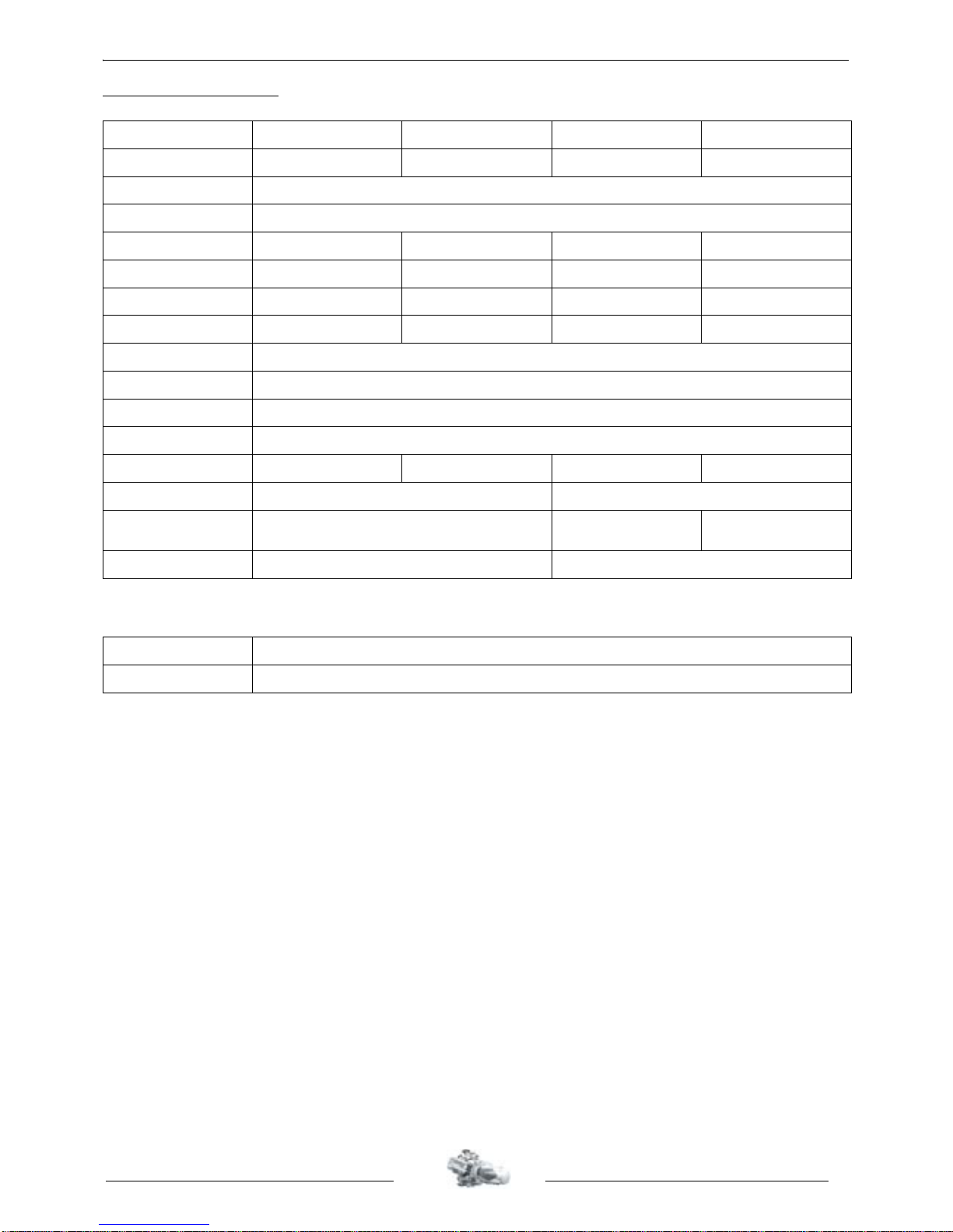
CHARACTERISTICS
Capacities
125 cc 150 cc 125 cc EFI 150 cc EFI
Marking FD1 FD2 FD4/FD5 FD4
Type 4-stroke single-cylinder
Cooling Liquid
Bore x stroke 57 x 48,9 mm 57 x 58,9 mm 57 x 48,9 mm 57 x 58,9 mm
Cubic capacity 124,8 cc 150 cc 124,8 cc 150 cc
Max. power output 9 kW at 8750 rpm 10 kW at 8450 rpm 9 kW at 8750 rpm 10 kW at 8450 rpm
Max. torque rating 7250 rpm 6500 rpm 7250 rpm 6500 rpm
Lubrication Trochoidal pump
Transmission By 2 variable pulleys and V-type belt
Clutch Centrifugal automatic
Exhaust Non-catalytic
Starter motor Mitsuba 440 W Mitsuba 470 W Mitsuba 440 W Mitsuba 470 W
Spark plug NGK CR7E NGK CR7EB
Magneto flywheel Mitsuba 235 W
Mitsuba
235 W/330 W
Mitsuba 235 W
Fuel supply Carburettor Indirect electronic injection (EFI)
Engine oil 1.25 l SAE 10W40
Relay box oil 0.12 l SAE 80W90 life lubricated
SPECIAL IMPORTANT POINTS
4
Reproduction or translation, even partial, is forbidden without the written consent of Peugeot Motocycles
SPECIAL IMPORTANT POINTS
Oil and fuel
This engine is designed to run on 95 or 98 unleaded fuel only.
Never run the machine with a petrol/oil mixture.
The fuel pipes must be changed if they show signs of wear, cracks, etc.
The clips are specific, they must always be changed each time they are removed
and replaced with new genuine parts clips.
Petrol is highly inflammable, do not smoke in the working area and avoid pr oximity to flames or
sparks. Work in a clear and well-ventilated area.
TIGHTENING TORQUE
5
Reproduction or translation, even partial, is forbidden without the written consent of Peugeot Motocycles
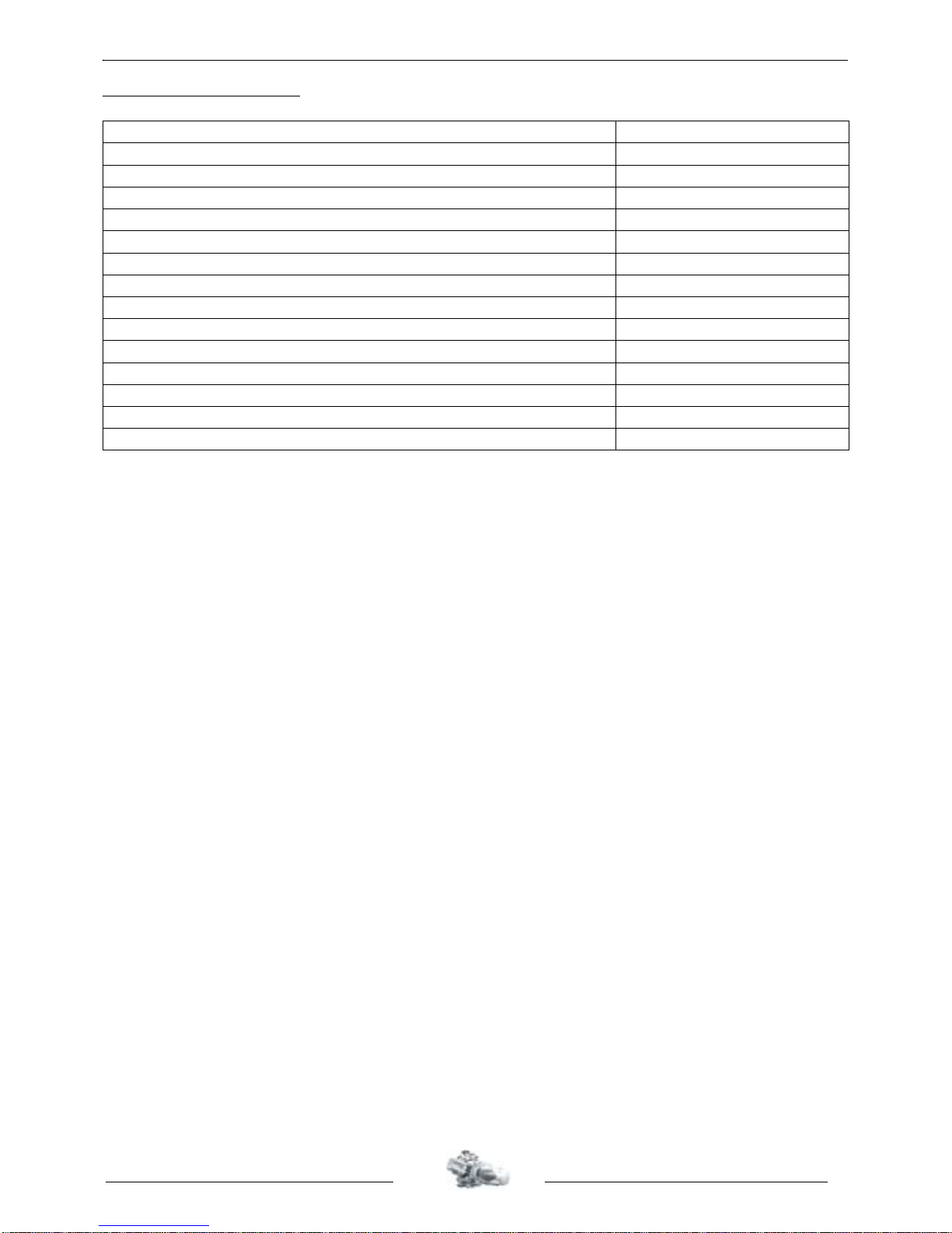
TIGHTENING TORQUE
Cylinder head 1.8/2.3 m.daN
Cylinder casings 1 m.daN
Transmission cover 1 m.daN
RH casing cover 1 m.daN
Automatic tensioner 1 m.daN
Oil control valve 4 m.daN
Temperature sensor 1 m.daN
Starter motor 1 m.daN
Rotor 7 m.daN
Stator 1 m.daN
Engine speed sensor 0.7 m.daN
Drive pulley 7 m.daN
Driven pulley 7 m.daN
Spark plug 1 m.daN
Camshaft gear 2.3 m.daN
SPECIAL TOOLS
6
Reproduction or translation, even partial, is forbidden without the written consent of Peugeot Motocycles
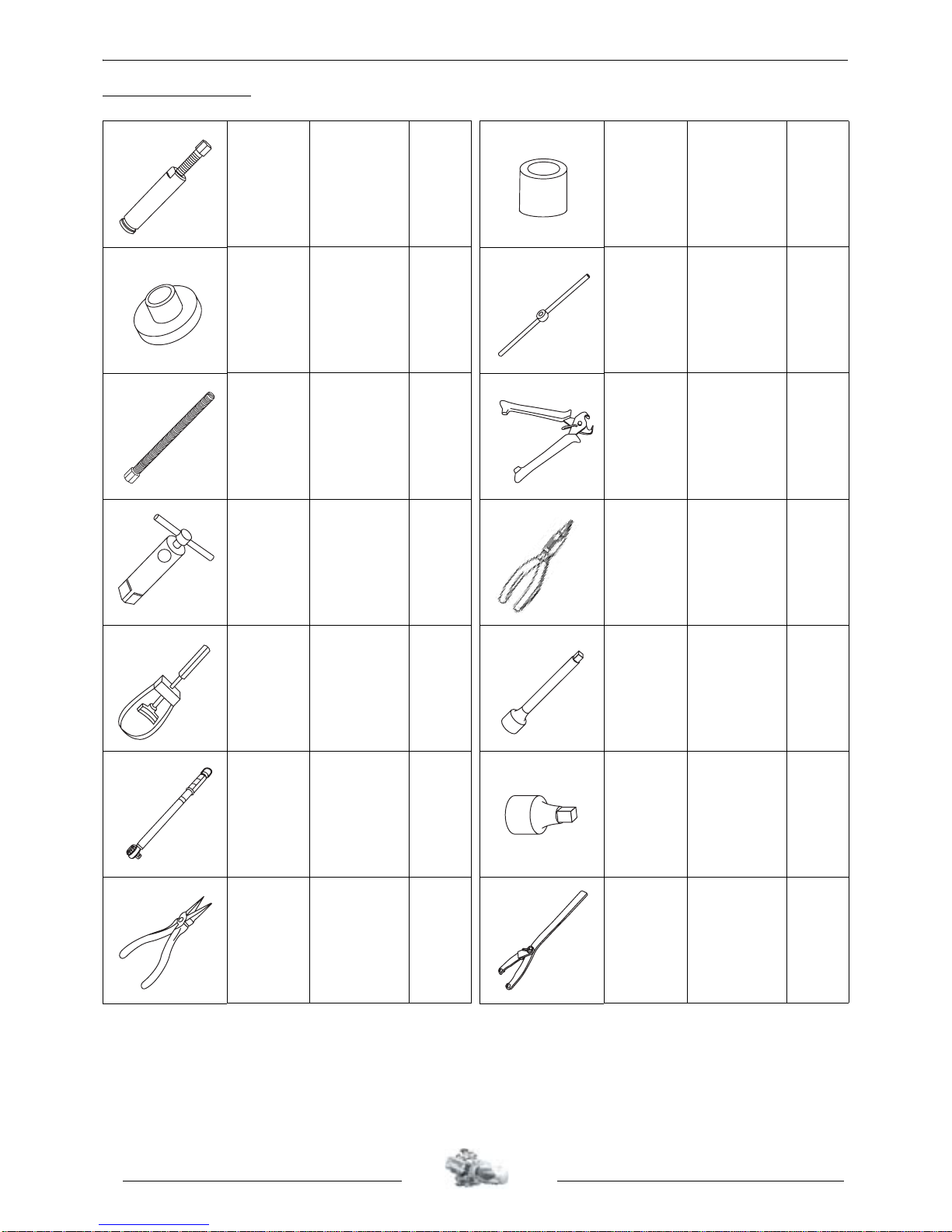
SPECIAL TOOLS
64706
Casing
extractor and
opening tool
Casing
opening
plate +
pin
69098
Protective
end-piece
large model
64706
64710
Shouldered
centering
tool
64706 69104 Pin nut
750 +
64711
+
64712
+
64754
64712
Pin Ø12
pitch 125
69104 750539
Tie-wrap
pliers
64765
Engine
mount
Engine
mount
adapter
752000
Piston circlip
pliers
68570
Flywheel
clamp
752235 1/2 extension
68994
or
753977
68994
Torque
wrench
8 N.m to
54 N.m
Extensi
on
752235
Adapter
752236
752236
1/2
3/8 adapter
68994
or
753977
69092
External
circlips pliers
752237
Adjustable
pin wrench
SPECIAL TOOLS
7
Reproduction or translation, even partial, is forbidden without the written consent of Peugeot Motocycles
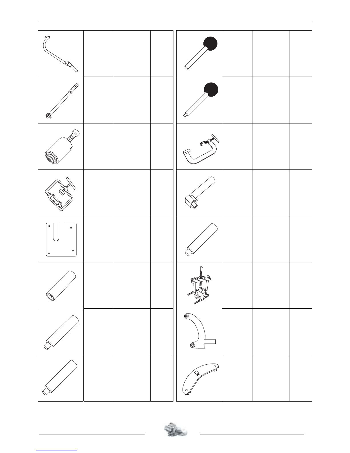
753711
Engine
mount
adapter
Elyseo
Elystar
64765 754033
Crankshaft
locking pin
753977
Torque
wrench
30 N.m to
150 N.m
752235
extensi
on
752236
adapte
r
754034
Camshaft
locking pin
754003
Flywheel
puller
69098 754035 Valve lifter
754005
Clutch
compression
tool
754046 754040
46 mm pipe
wrench
754005
754006
Casing
opening
plate
64706 754041
Timing
casing seal
drift
754007
Mechanical
seal drift
755585
Bearing
extractor tool
754008
Water pump
seal drift
756717
Engine
mount
adapter
Jetforce
64765
754009
Water pump
pin drift
757035
Fixed flange
locking tool
SPECIAL TOOLS
8
Reproduction or translation, even partial, is forbidden without the written consent of Peugeot Motocycles
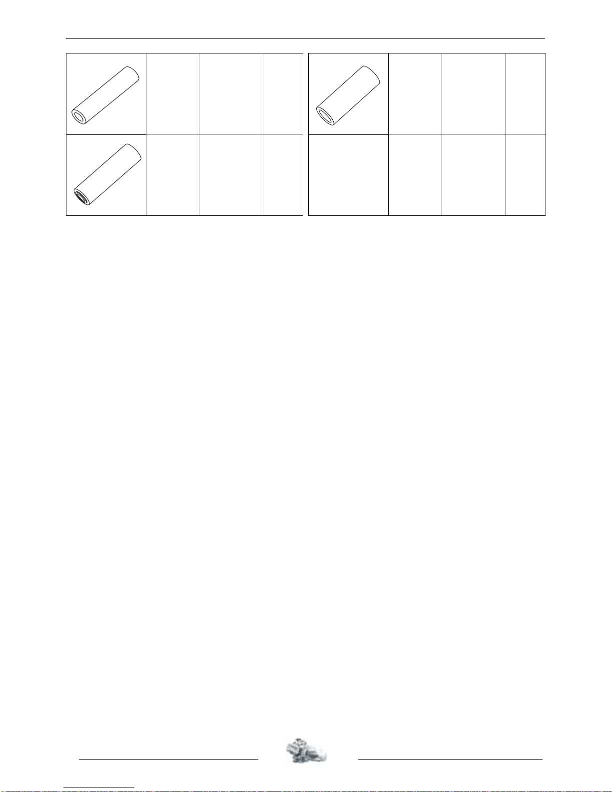
757988
Water pump
bearing drift
757989
Water pump
bearing drift
757990
Crankcase
seal
installation
buffer
DISASSEMBLY
9
Reproduction or translation, even partial, is forbidden without the written consent of Peugeot Motocycles
DISASSEMBLY
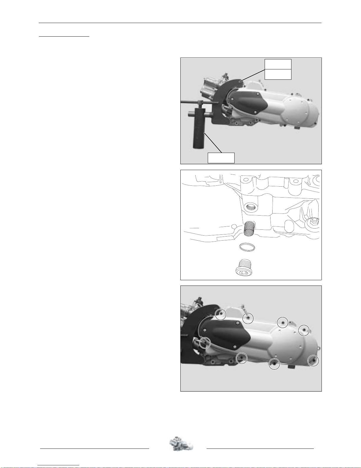
Putting the engine on the stand.
- Put the engine on the jig:
P/N 753711 for engines FD1, FD2 and FD4.
P/N 756717 for engines FD5.
- Put the assembly on stand P/N 64765
clamped in the jaws of a vice.
- Empty the oil from the engine
Note: Every time oil is changed, the filter
must be cleaned and the copper seal
changed.
- Tightening torque: 4 m.daN.
Removal of the primary transmission
cover.
- Remove the 8 bolts that secure the cover.
- Remove the transmission cover and the
2 centring pillars.
- Tightening torque: 1 m.daN.
.
756717
753711
64765
DISASSEMBLY
10
Reproduction or translation, even partial, is forbidden without the written consent of Peugeot Motocycles
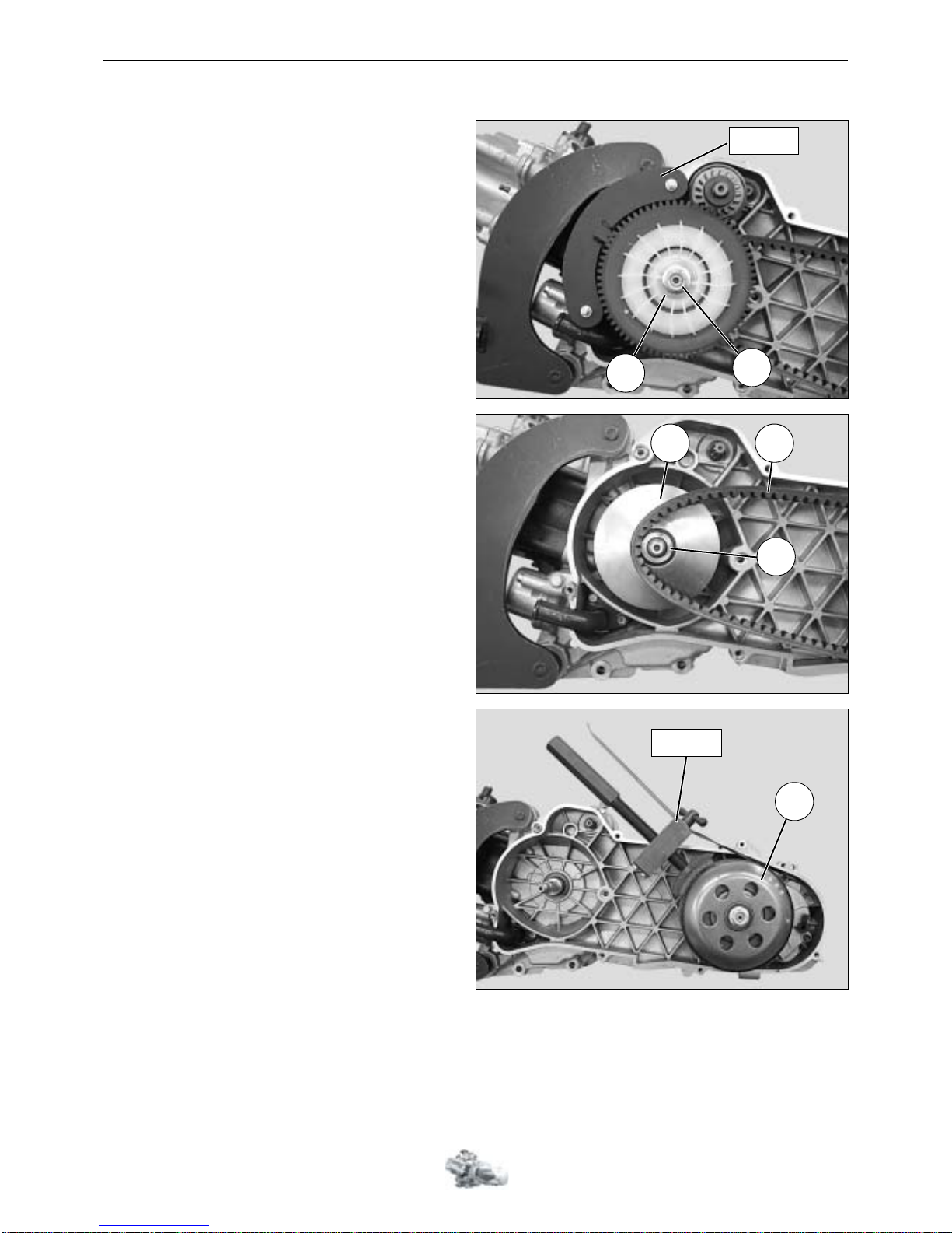
Removal of the drive pulley.
- Remove the starter dog.
- Hold the fixed flange with tool P/N 757035.
- Remove the nut (1) and washer (2) from the
fixed flange
- Remove the fixed flange.
- Tightening torque: 7 m.daN.
- Remove the belt (3).
- Remove the drive pulley (4) with the guide
hub (5).
Removal of the driven pulle y.
- Immobilize the clutch drum using the ajustable
pin wrench P/N 752237 or the flywheel clamp
P/N 68570.
- Remove the nut.
- Remove the clutch drum and the clutch and
drive pulley assembly.
- Tightening torque: 7 m.daN.
757035
2
1
5
4 3
1
68570
DISASSEMBLY
11
Reproduction or translation, even partial, is forbidden without the written consent of Peugeot Motocycles
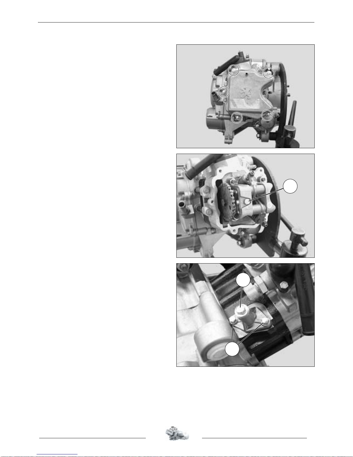
Removal of the rocker cover.
- Remove the 5 fixing bolts.
- Remove the rocker cover.
- Remove the paper gasket.
- Tightening torque: 1 m.daN.
Note: The O-ring must be changed every
time it is removed.
Every time the rocker cover is removed and reinstalled, make sure the plug (1) is over the
gauge hole of the cylinder head.
Removal of the chain tensioner.
- Remove the screw and spring from the
tensioner (1).
- Remove the 2 mounting screws (2) from the
tensioner body.
1
1
2
DISASSEMBLY
12
Reproduction or translation, even partial, is forbidden without the written consent of Peugeot Motocycles
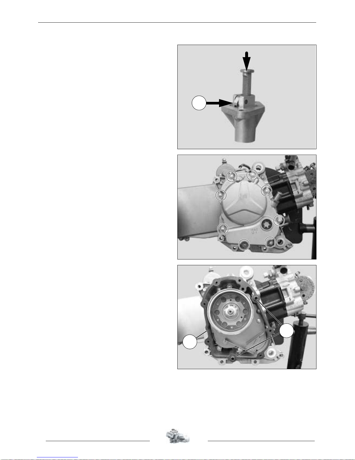
- Remove the chain tensioner and slacken it by
pressing the ratchet tooth (A).
- Remove the paper gasket.
- Tightening torque: 1 m.daN.
Removal of the RH cover / ignition coil
and sensor.
- Remove the 8 bolts that secure the RH cover.
- Remove the cover.
- Tightening torque: 1 m.daN.
- Remove the paper gasket (1) and the
2 locating pins (2).
A
2
1
DISASSEMBLY
13
Reproduction or translation, even partial, is forbidden without the written consent of Peugeot Motocycles
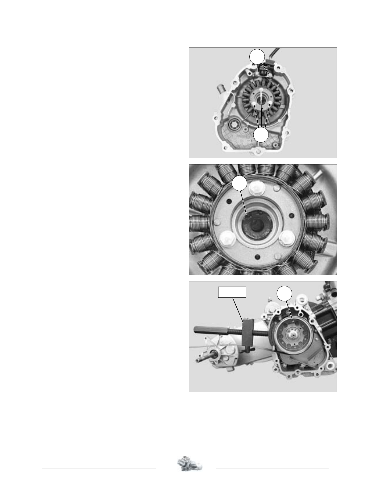
- Remove the engine speed sensor 2 fixing
bolts (3) and the stator assembly 3 fixing
bolts (4).
- Remove the stator and sensor assembly (3).
- Setting the engine speed sensor gap: 0.3 to
1.4 mm.
- Tightening torque: 1 m.daN.
Note: The oil flowing inside the cover and
the crankshaft stem shall lubricate
the conrod big end..
The tighteness of the oil lubrication system
between the cover and the RH stem of the
crankshaft is provided by a seal
The seal is placed in the casing with its lip on the
casing side.
A circlip (5) holds the seal in its housing
The condition of the seal shall be checked every
time the cover is removed. And if necessary it
shall be replaced using the timing casing seal
drift P/N 754041.
Removal of the rotor.
- Immobilize the rotor (1) using the flywheel
clamp P/N 68570
- Remove the nut.
3
4
5
1
68570
 Loading...