

Page 1

Containment System
Operation Guide
This Innotek® electronic dog collar is among the safest, most
humane and effective training products you can buy. Used properly, the collar's electronic stimulus serves as a distraction that
your dog will find undesirable. By obeying, your dog quickly learns
to shut off the stimulus, thus gaining confidence in response to
your commands. Like most Innotek training products, this collar
has adjustable stimulation levels. This feature allows you to use
the level that best matches your dog's temperament.
CAUTION
Please take a few minutes to read the instruction manual prior to your first use. This instruction manual contains
important programming and set-up information to help your training proceed as successfully as possible. For best
results, follow these important rules:
• The electronic dog collar is intended only for use on dogs.
• Most dog owners are surprised at how much can be accomplished by using low-level stimulation;
therefore, use the lowest stimulation necessary to get the desired behavior.
• A low battery may cause intermittent operation. DO NOT USE if you suspect a low battery.
• Allow your dog to get used to the collar before you begin training. You want your dog to accept the
collar as part of a routine, not to associate the collar with correction.
• DO NOT leave the collar on your dog for more than 12 hours per day.
• NEVER perform set-up procedures when the collar is on your dog.
• An electronic collar should only be used under close supervision by the dog's owner.
• KEEP OUT OF THE REACH OF CHILDREN.
• Read all instructions before using this product. If you have questions or concerns, contact your
nearest INNOTEK dealer or service center.
IMPORTANT
Realize that because individual dogs have unique temperaments, there is no way of knowing how your dog will
react to its introduction to this product. For the safety of your dog, initial training should take place using a long
leash to keep you in control of the situation. Also realize that an aggressive animal could turn against the handler
upon receiving the stimulus. Therefore, if you feel your dog has an aggressive behavior and/or it has a history of
aggressive behavior,you should consult a certified animal behaviorist before using this product. Please refer to the
Training Your Dog, Section 3 on Page 9.
HOW IT WORKS
The boundary wire is connected to the wall transmitter powered by an AC adapter.When the containment system
is turned on, a radio signal is transmitted through the wire. If a dog wearing the collar receiver approaches the
wire, the signal causes the collar receiver to deliver a brief, harmless correction.The dog naturally seeks to avoid
the wire and thus quickly learns to stay within the established boundaries.
1
Ne Onzichtbare omheining 15
Fr Guide d’emploi 30
De Bedienungsanleitung 45
It Guida di funzionamento 60
Es Guia de Funcionamiento 75
Page 2

SSEECCTTIIOONN 11..
IINNSSTTRRUUCCTTIIOONNSS FFOORR SSEETTTTIINNGG UUPP YYOOUURR CCOONNTTAAIINNMMEENNTT SSYYSSTTEEMM
This owner’s manual covers the instructions for both the battery-operated collar receiver and rechargeable collar
receiver containment systems. Throughout this manual are notes pertaining to each of these system types.
STEP 1.
PREPARE A LAYOUT OF YOUR CONTAINMENT AREA
A. Design and Draw Diagram
Prepare a diagram of the area you want to contain your dog. A diagram will help to avoid unforeseen obstacles.
Include the location of house, driveway, pond, garden, swimming pool,etc.If your neighbor has a containment system installed, mark the location of the buried wire on your diagram.
B. Contact Utility Company
Contact your utility companies to mark any buried utility lines. Be sure to include the buried lines on your drawing
because these utility lines will affect the placement of your wire.
C. Determine Location of Wall Transmitter
The transmitter can be mounted to a wall near any standard 220-volt household outlet with the included screws.
It will withstand freezing temperatures, but it is not waterproof. Therefore, it is best to locate the transmitter in an
enclosed area.
NOTE FOR RECHARGEABLE SYSTEMS: The wall transmitter must be mounted in an environment where the
ambient temperature is between 0 degrees C and 45 degrees C.
D. Determine the Exit Route of Your Boundary Wire from the Transmitter to the Outside Containment Area
Since your transmitter must be mounted in an enclosed area to protect it from the weather, give careful consideration on where the wire exits to the exterior.Existing openings such as a window,door or utility line hole may provide easy access to the outside. You may need to drill a hole through the exterior wall.
STEP 2.
ADD PROPOSED WIRE LOCATION TO YOUR DRAWING
Mark your diagram with the proposed location of your wire. This will provide an easy reference as you install the
wire.
For the system to work properly, the wire must make one continuous loop. The signal is transmitted from one terminal of the transmitter,through the wire and back to the other terminal.
To allow back door entry with back
yard containment.
To keep dog away
from a specific area.
Example Installation Diagrams
To enclose the entire property and
protect a selected area.
2
Page 3

IMPORTANT NOTES FOR WIRE PLACEMENT:
• Do NOT run the loop within 2 meters parallel to electrical, telephone, cable TV, or other
buried wire in the yard.
• Do NOT run one section of wire within 3 meters of another section or the signal may
cancel.
• Do NOT run your wire within 3 meters of any adjacent containment system’s wire.
STEP 3.
ESTIMATE THE AMOUNT OF WIRE NEEDED
Both the battery-operated and rechargeable models include 152 meters of boundary wire. It can enclose an area
of nearly .2 hectares.
The amount of wire needed is determined by several factors:
(a)Total area to be contained
(b)Using a double loop. This requires twice as much wire.
(c)Size of the signal field. The signal field is the distance from the wire
to the place where the collar receiver first activates. A 3 to 4 meters
wide field is preferred.
Additional boundary kits (available separately) allow you to add wire to contain
a larger area. The battery-operated model can contain up to 2 hectares. The
rechargeable model can contain up to 10 hectares. Each boundary kit includes
152 meters of wire, 50 training flags, and two waterproof wire splices.
STEP 4.
INSTALL THE WALL TRANSMITTER
Install the wall transmitter close to a standard 220-volt household outlet. Do not plug the transmitter to the outlet until the
boundary wire is in place.
STEP 5.
DETERMINE YARD SIZE SETTING
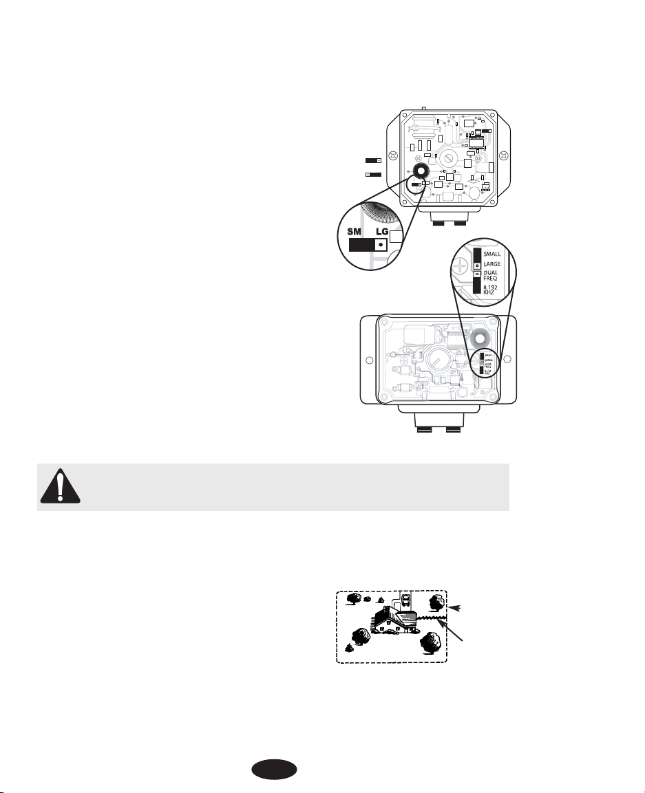
The wall transmitter contains an internal jumper that can be
adjusted for small or large yards. The jumper is pre-set at the
factory for small yards. The small yard setting is for an area
that requires less than 300 meters of wire. A large yard setting is for an area that requires more than 300 meters of wire.
Charging Pin
(rechargeable only)
Indicator Light
Field
Width
Power
Port
Wire Terminals
For illustration only. Your
transmitter may vary
slightly in appearance.
3
INDICATOR LIGHT
Field
Width
Page 4
If it is necessary to change the yard size setting:
1. Turn the Field Width knob to the “off” position.
2. Remove the knob and the four screws that secure the transmitter’s cover.
3. Move the jumper to the desired yard setting. The jumper must be
in place for the transmitter to function.
• Rechargeable Systems Only: The jumper is located at the lower
left side of the transmitter. SM is for small yards; LG is for large
yards (see Figure 1).
• Battery-Operated Systems Only: The jumper is
located at right side of the transmitter. SMALL is for
small yards; LARGE is for large yards. A second
jumper is labeled "DUAL FREQ" and "8.192 KHz." This
jumper should always be in the "8.192 KHz" position
unless otherwise directed by an INNOTEK Service Center
(see Figure 2).
4. Replace the transmitter cover and the four screws.
5. Reinstall the Field Width knob with the pointer in the "off" position.
STEP 6.
LAY OUT THE PERIMETER WIRE
IMPORTANT NOTE: Do NOT bury the wire until you have tested the system and are sure it is working
properly. Do NOT nick or scrape the wire during installation. Improper function may result.
1. Use your drawing as a reference. Begin laying the wire around the perimeter of your containment
area to form a continuous loop. Use gradual turns at the corners with a minimum of 1meter radius.
This provides a more consistent signal field.
2. If you are using more wire than initially supplied with your
containment system, the wire connections must be waterproof to provide a sealed connection between the wires.
Use only the supplied splices or a comparable type. Do not
use electrical tape or twisted wire nuts. This will cause an
intermittent signal or disarm the system.
3. Continue around your perimeter until you return to the start
of the loop.
4. Cut the wire.
SM LG
MED LO
SM LG
SM LG
Figure 1
Rechargeable System
Figure 2
Battery-Operated System
Wall Transmitter
Located in Garage
Perimeter Wire
Twisted Wire
to Wall
Transmitter
Installation Diagram
4
Page 5

STEP 7.
CONNECT THE PERIMETER WIRE TO THE WALL TRANSMITTER
The wire from the perimeter to the wall transmitter should be twisted to cancel the signal. This allows the dog to
cross the area without receiving a correction. It also eliminates possible interference from electrical wires, etc.
1. Measure the distance from the wall transmitter to the edge of the perimeter wire.
2. Because twisting the wire decreases the length of the wire, multiply the distance by 1½.
3. Measure and cut two wires of equal lengths of the above measurement.
4. Hold the two ends of the wire side by side and twist them together. The wires
can be twisted manually or by using a power drill until the twists are 6 to 12 cm
apart. The tighter the wire is twisted the better the signal cancellation.
5. Use the supplied waterproof splices for all in ground connections. To use the
splices, strip
5
/8” of insulation from the ends of the wires you are joining. With
the ends of the wires even and together, place the wire nut over the wire ends
and turn the wire nut clockwise until it is securely fastened. Snap open the
hinged lid of the gel-filled capsule and insert the wire nut as deeply as possible
into the waterproof gel. Snap the lid shut, making sure the wires exit the splice
on either side. Tie a knot in the wires as shown in the diagram to prevent them
from pulling out of the gel-filled capsules when the wire is buried.
6. Repeat Step 5 for the other end of the twisted wire and other end of the perimeter wire. One hole of the splice will not be used.
7. Put the twisted wires through the existing opening or drilled hole so it can be
connected to the transmitter.
8. Strip off about 1 cm of insulation from the end of each twisted wire.
9. Insert the wires into the terminals of the transmitter.
10. Plug the power adapter into a standard 220-volt household outlet.
11. Connect the power adapter to the transmitter’s power port.
STEP 8.
VERIFY TRANSMITTER IS FUNCTIONING PROPERLY
To verify the transmitter is functioning properly, look for a red light on the transmitter. A continuous
red light tells you that the transmitter is receiving power, both wires are connected, and the wire
forms an unbroken, continuous loop. The transmitter light indicates continuity only.
If the red light does not appear, it means that one or both wires are not properly connected; both
wires are connected but the wire is broken; the transmitter has malfunctioned; or the power has
been turned off. Correct the problem and retest.
STEP 9.
SET UP YOUR COLLAR RECEIVER
Before proceeding, you must first make sure the system is functioning properly with the collar
receiver. Part A pertains to the rechargeable collar receiver only; Part B applies to the battery-operated collar receiver.
A. Rechargeable Collar Receiver
5
Wire
Gel-filled
capsule
Wire nut
Wire
Page 6

The following instructions apply to the battery-operated collar receiver only. If your collar receiver is
battery-operated, please proceed to Part B below.
The collar receiver is charged via the wall-mount transmitter.To charge the collar receiver for initial
use, you must first install the transmitter.
The rechargeable collar receiver must be charged for at least 12 hours before you use it
for the first time. IMPORTANT! DO NOT BURY THE WIRE UNTIL YOU HAVE TESTED THE
SYSTEM WITH YOUR COLLAR RECEIVER AND ARE SURE IT IS WORKING PROPERLY.
IMPORTANT NOTE: The containment system will not function while the collar receiver
is charging. Therefore you should either plan a) to charge the collar receiver only when
your dog can be supervised or otherwise contained; or b) to purchase an additional collar receiver
and charger from INNOTEK and charge one collar receiver while the
other is in use. To order an additional collar receiver and charger,
contact an INNOTEK Service Center.
To charge the collar receiver:
1. Turn the wall-mounted transmitter on and place the
collar receiver on top of it. Make sure the transmitter’s
raised alignment pin fits into the small indentation on the
bottom of the collar receiver.
2. Check that the transmitter is blinking. This indicates
that the collar receiver is being charged. If the transmitter
is not blinking, check that the transmitter is turned “on” and
check all of the connections.
3. The blinking indicator light will go out when the collar receiver is fully charged.
INNOTEK’s chargers automatically prevent over-charging.
4. Depending on the frequency of correction, the charge in the collar receiver usually
lasts between 2 and 3 weeks.
IMPORTANT NOTE: Do NOT place the collar receiver on your dog until the containment
system has been tested and the signal field adjusted.
5. Proceed to Step 10 below to test your system for proper functioning.
B. Battery-Operated Collar Receiver
The following instructions apply to the battery-operated collar receiver only. If
your collar receiver is rechargeable, please refer to Part A above.
Collar Receiver Battery Installation
1. Place the collar receiver on a flat surface with the battery cap facing up.
2. Using a coin or a screwdriver, unscrew the battery compartment cap.
3. Insert the 6-volt alkaline battery (included) into the battery compartment with
the positive (+) side up.
4. Replace the battery compartment cap. Being careful to keep the cap in contact with the battery,
turn the cap clockwise until it is firmly seated.
5. Depending on the frequency of correction, the battery in the collar receiver usually lasts
6
Page 7

between 2 and 3 weeks.
IMPORTANT NOTE: Do NOT place the collar receiver on your dog until the containment
system has been tested and the signal field adjusted.
STEP 10.
TEST THE CONTAINMENT SYSTEM
DO NOT TEST THE CONTAINMENT SYSTEM WITH THE COLLAR RECEIVER ON THE DOG. You must
manually test the containment system to verify that the signal is properly transmitted through the
wire. Use the supplied test light.
NOTE FOR RECHARGEABLE SYSTEMS: The containment system will not function while the collar
receiver is charging on the transmitter.
To test the system:
1. Turn the field width knob so the arrow is pointed halfway between the “off”
and “high” positions.
2. Position the test light on the probes so that the tips of the
probes make contact with the wires inside the two openings
(see diagram). Gentle pressure may be needed.
3. Hold the receiver box without touching the probes.
4. Hold it at the height of the dog’s neck with the probes pointed upward.
5. Slowly walk the collar receiver toward the wire. Listen for the warning tone
and watch for the test lamp to light. The light will be dim for mild stimulation
and
bright for the intense stimulation.
STEP 11.
ADJUST THE SIGNAL FIELD WIDTH
The signal field is the distance from the wire to the place where the collar
receiver first activates. The Field Width Knob adjusts the size of the signal field,
not the correction intensity.Turning the knob clockwise increases the signal field
width; turning it counterclockwise decreases it. Turning the knob completely
counterclockwise switches off the transmitter power.
Follow the instructions in Step 10 to test the signal field width. Walk the entire perimeter to be sure
that the signal field is consistent throughout your containment area. The signal field should extend a
minimum of 2 meters on either side of the wire (creating a 4 meter wide field). A 3 to 4 meter wide
field is preferred. The wider the signal field width, the less chance that a dog can run through the field.
• If your yard size setting jumper is set for a small yard and you cannot turn the signal field width
any wider, move the jumper to the large yard size setting. See Step 5, Determine Yard Size Setting
for instructions. Retest the signal field width.
• If your yard size setting jumper is set for a large yard and you cannot turn the signal field down
7
Field
Width
Page 8

any farther, move the jumper to the small yard size setting. See Step 5, Determine Yard Size Setting
for instructions. Retest the signal field width.
The transmitter light indicates continuity only. If you have a loose splice or nicked wire, the red light
or
a flickering light may still show, but you may notice reduced or no field width. If this situation or a
wire break should occur, follow the instructions in the Troubleshooting Section located near
the end of this guide.
NOTE FOR BATTERY-OPERATED SYSTEMS: Make sure the second jumper inside the wall transmitter is set for 8.192 KHZ. This is the factory setting and should not be changed unless directed by
an INNOTEK Service Center.
IMPORTANT NOTE: If the Field Width knob is removed or the position of the knob is altered by turning it clockwise or counterclockwise, you must always check the signal field for the desired setting.
Refer to Step 10, Test the Containment System.
STEP 12.
INSTALL THE BOUNDARY WIRE
Tools Needed - Straight-edged spade, wire cutter / stripper, and standard screwdriver. If you plan
to run the wire across concrete, you will also need a caulk gun, silicone caulking, and a circular saw
with a masonry blade.
Placing the Wire - For the system to work properly, the wire must make one continuous loop.
Burying the Wire - The wire does not have to be buried, but for protection you probably want to
bury it at least one inch underground. Start by digging about 7 to 10 cm deep where the wire first
enters the ground near the transmitter and continue around the path of the loop wire. Note: When
covering a large area, you may wish to use a trenching machine to cut into the ground. However, we
recommend that the wire be placed in the trench by hand. A commercial wire-placing machine may
break the wire.
Driveways / Sidewalks - When crossing an asphalt driveway, make a 2 cm deep cut across the
driveway using a circular saw and masonry blade. Place the wire in the crack and seal with asphalt
sealant. On driveways and sidewalks, if an expansion joint is available, simply place the wire in the
joint and seal with an outdoor caulk. When crossing gravel, bury the wire at least 7 cm deep. Use an
old garden hose or plastic PVC piping to protect the wire. In water, anchor the wire with large rocks.
Protect the wire with an old garden hose or plastic PVC piping.
STEP 13.
INSTALL THE BOUNDARY TRAINING FLAGS
After installing the wire, retest the containment system as described in Step 10, Test the
Containment System. Verify that the signal field width is consistent by following the instructions in
Step 11, Adjust the Signal Field Width. As you are retesting and verifying the system,
install the boundary training flags. Place the flags where the warning tone is first heard
as you approach the wire. The flags should be placed at the edge of the signal field width,
8
Page 9

not directly on the wire. This will add a visual cue to the audio warning tone and help your dog to
learn the boundary.
STEP 14.
FITTING THE COLLAR TO YOUR DOG
IMPORTANT NOTE: Never leave the collar receiver on the dog for longer than 12 hours a day.
Leaving the collar on the dog for extended periods could result in skin irritation. Check your dog's
neck periodically for skin irritation.
A. Probes
• Make sure both probes contact the dog's skin. If needed, a small amount of hair removal or thinning will improve probe contact with the skin.
• Use short probes for short-haired dogs. Use long probes for long-haired dogs. Special probes are
available for especially thick-haired dogs. Contact INNOTEK to order.
• Finger-tighten the probes, then turn them one additional revolution with the probe wrench. Do not
over-tighten.
• Always use the rubber insulators between the collar strap and probes to provide insulation in
damp conditions.
• Check the tightness of the probes regularly to prevent loss of the receiver box.
B. Collar Strap
•To prevent accidental correction inside the home, remove the collar from the dog’s neck when it
comes inside.
• Place the collar around the dog's neck with the receiver box under the chin. The collar must be on
relatively tight to keep the probes making skin contact without restricting breathing. You should be
able to slide only one finger under the strap at the back of the dog's neck.
• Always make sure the collar is functioning properly BEFORE putting it on the dog.
• Remove other metal collars when the dog wears the containment collar. Metal collars may interfere with proper operation.
• Remove the collar and trim the excess strap, leaving 4 to 6 inches.
SECTION 2.
HOW THE CORRECTION WORKS
1. Pre-Correction Warning Tone: When the dog reaches the edge of the signal field in the yard, it
will hear a warning tone that lasts about two seconds. If the dog does not return to the safe part of
the yard, it will receive a continuous correction until it returns to the safe area.
2. Run-Through Prevention: The receiver automatically increases the correction as the dog enters
the signal field. The dog cannot "run through" the signal field without receiving a strong correction.
3. Over-Correction Prevention: In the unlikely event that the dog becomes "trapped" in the signal
field, the system shuts off for 10 seconds before resuming correction for another 20 seconds. This
pattern will alternate until the dog retreats to the safe area or the system is turned off.
9
Page 10

SECTION 3.
TRAINING YOUR DOG
To get the most out of your containment system when training, keep these tips in mind:
•To prevent accidental correction inside the home, remove the collar from the dog’s neck when it
comes inside.
• Always make sure the collar is functioning properly BEFORE putting it on the dog. Verify the system is operating properly and the field width is appropriate as described in Section 1, Step 11,
Adjust the Signal Field Width.
• Stay positive and playful during the training session.
• Keep training sessions brief. Never continue a session after your dog has lost interest. Take a
break to rest or play.
• ALWAYS praise your dog for good behavior.
The following steps outline a successful training plan:
STEP 1.
FLAG TRAINING
1. Turn the wall transmitter “off” so no corrections will be given to your dog.
2. Place the collar receiver on your dog.
3. Place a long leash on your dog. Play with your dog in the safe area of the yard for 2-4 minutes.
Do not allow your dog to run free or cross the flag lines.
4. Walk towards the flags. Reach down and shake a flag. Say "bad flag" in a disapproving tone.
5. Return to the center part of the yard and play with your dog. Reward with treats.
6. Repeat this exercise several times in various locations of the yard.
STEP 2.
THE FIRST CORRECTION
1. You need to reset the signal field width before placing the collar receiver on your dog. Follow the
instructions outlined in Section 1, Step 11, Adjust the Signal Field Width.
2. Place the collar receiver on your dog in the safe area of the yard.
3. Place a long leash on your dog. Play with the dog in the safe area of the yard.
4. Walk towards the flags. If your dog tries to avoid the flags, praise and reassure your dog.
5. Repeat this step in other locations of the yard.
6. Allow no more than three corrections in a day or seven in a week.This depends on your dog’s
stress tolerance. Most dogs only receive a few corrections during the training phase; they respond
to tone very quickly.
7. Reward your dog when it avoids the flags, even if a correction is issued.
8. Play in the safe zone with your dog before ending this training session.
STEP 3.
ON-LEASH PROOFING
1. With the collar on your dog and the wall transmitter “on”, play with your dog (on leash) in the
safe area. After a few minutes of play, toss a toy or treat through the flags.
10
Page 11

2. If your dog runs through the flags to chase the toy, wait for the startled response and pull your
dog back into the safe area. Praise and reward your dog.
3. Reinforce training by shaking a flag. Say "bad flag" with a disapproving tone. Consider increasing
the signal field area. If you choose to increase the signal field area, remove the collar from your dog,
increase the signal field, and retest. Refer to Section 1, Step 11, Adjust the Signal Field.
4. Repeat this exercise in other locations of the yard.
5. Praise your dog when it avoids the flags. Stay positive and playful during the training session.
6. When your dog refuses to run through the flags 20 consecutive times, proceed to the next step.
STEP 4.
OFF-LEASH PROOFING
1. Follow the instructions in Step 3, On-Leash Proofing except drop the leash on the ground. It will
be available if you need to retrieve your dog.
2. If your dog gets through the signal field during this phase, quickly remove the collar. Bring your
dog back into the safe area. Put the collar back on your dog. Reinforce "bad flag" training. Praise
and reward your dog.
3. Repeat this off-leash training until you are confident that your dog will ignore temptations outside
the containment area.
SECTION 4.
SYSTEM MAINTENANCE TIPS
Your system requires very little maintenance. The battery-operated collar receiver is water resistant
and should not be immersed in any liquid. This will cause damage not covered under the manufacturer’s warranty. The rechargeable collar is waterproof and will continue to function after being submerged in water.To remove dirt, simply wipe withsoap and water.Never place the collar in a dishwasher.
The wall transmitter is not waterproof and must be protected from the weather.A close lightning
strike may damage the unit. Unplug the transmitter and disconnect the wires during storms.
Do not attempt to dismantle or repair any of the system components; this will void the manufacturer’s warranty. These components contain computerized circuitry that should be serviced only by an
authorized expert.
Test the system once a week to make sure the collar receiver is working properly. Also, testing the
system will verify the field width setting is correct. To test, attach the supplied test light to the collar
receiver probes. Holding the receiver by the case, NOT by the probes, walk into the signal field.
Listen for the warning tone to sound and the test light to illuminate.
NOTE FOR RECHARGEABLE SYSTEMS:
Every six months, the collar receiver should be allowed to discharge fully and then be recharged. To
discharge the receiver, turn the system on and place the collar receiver with the test light attached
in the signal field. When the receiver stops emitting a tone and illuminating the test light, it is fully
discharged. Always use the test light when discharging the collar receiver. Failure to do so can permanently damage the collar receiver.
SECTION 5.
11
Page 12

TROUBLESHOOTING GUIDELINES
A. Dog is not responding to correction:
• Adjust the collar fit.
• Trim the dog’s hair or use longer probes to make better skin contact.
• Change and/or recharge the battery in the collar receiver.
• Be sure the wall transmitter jumper is set at 8.192 kHz. (Battery-operated receiver system only).
For more information, visit our web site at www.innotek.net.
NOTE FOR RECHARGEABLE SYSTEMS ONLY:
If your dog is not responding to the correction, the rechargeable
system has the option of setting the correction level on the
wall transmitter for Low, Medium, or High. The factory setting is
Medium. If you want to change the level:
1. Turn the Field Width knob to the “off” position. Remove
the
knob, the four cover screws and the front cover.
2. The jumper in the upper right corner of the transmitter can
be moved to the right for the Low setting or completely
removed for the High setting.
3. Replace the transmitter cover and the four cover screws
4. Install the knob with the pointer to the “off” position.
5. Retest the signal field width as described in Step 10.
NOTE: If the transmitter is set on High, there will be
no pre-correction warning tone.
B. System Test Procedure:
Whenever you experience a malfunction, you will need to do a Test
Loop to determine which component - collar, wall transmitter, or
yard wire - is not working. To perform the Test Loop procedure:
1. Make a test loop using a piece of wire at least 4 meters in length.
2. Remove the existing wire from your wall transmitter.
3. Insert the two ends of the test loop wire into the wall transmitter.
4. Turn the field width knob to the 9 o’clock position or a low setting.
5. Place the test light on the collar receiver. With the collar in hand,
move outside the field and approach the test loop. Make a mental
note of the distance between the collar and the wire when the collar
activates.
6. Turn the field width knob to 12 o’clock or a medium setting.
7. Back away from the wire and approach it again. Determine the
distance between the collar and the wire when the collar activates.
The distance should be greater on the medium range setting.
8. If more than one collar receiver is used with the system, repeat the above test on each collar.
12
INDICATOR LIGHT
SMART DOG
Field
Width
Page 13

Results of System Test Procedures:
If there is no red light on the wall transmitter with the test loop wire in place, the wall transmitter is
malfunctioning.
If the red light is solid on the wall transmitter, but the collar does not
activate on the test loop wire, the collar receiver is not working.
Change or recharge the battery in the collar receiver and repeat the
test.
If the red light is solid on the wall transmitter and the collar receiver
activates as you approach the test loop wire, the problem is in the yard
wire.
C. To Locate Wire Breaks:
To locate wire breaks in the loop installation, use a wire break location device called a RF- Choke. It
is available through the RadioShack
®
(Catalog #273-102C). Once you have this device, follow these
steps:
1. Disconnect the power by unplugging the adapter from the outlet.
2. Disconnect the wires from the wall transmitter.
3. Bend the leads of the RF-Choke into the shape of a horseshoe.
4. Gently wrap the wire (stripped) ends around the
RF-Choke leads (one to each side).
5. Plug the RF-Choke leads into the terminals on the transmitter.
6. Plug the adapter into the outlet.
7. Set a portable radio to a frequency near 600 kHz on the AM band.
8. Set the field width knob high enough to obtain a signal on the portable radio when holding the
radio over the containment wire.
9. The signal should be absent on the twisted wire portions because twisting cancels the signal.
When you reach a single wire area of your boundary, listen for pulsating static on the radio.
10. Hold the radio chest high and swing the radio over the wire as you walk along the boundary.
11. If the tone stops, weakens, or changes pitch, mark the spot with a flag or stick. No sound indicates a complete break in the wire. If the signal fades or changes in pitch, look for a nick in the
insulation.
12. Continue around the remaining boundary and mark each signal change with a flag or stick.
13. After completing the entire boundary, return to the marked spots. Examine the wire for 3 to 4
feet in each direction.
14. Replace the damaged wire using the same gauge wire used in the original installation and use
waterproof wire splices to make the connection.
For more information, visit our web site at www.innotek.net.
LIMITED INTERNATIONAL WARRANTY
13
Page 14

INNOTEK™ warrants that its products will be free from defects in material and workmanship under normal use
for one year from the date of original consumer purchase.
Within 30 days of the original consumer purchase, products are covered by INNOTEK’s 30-day money-back guarantee and/or local country consumer law. If you are not satisfied with the performance of the product, you may
return it with the original receipt to the place of purchase for a full refund. A refund is subject to the retailer’s return
policy.
After 30 days and during the Limited Warranty period, products covered by this Limited Warranty will be repaired
by an INNOTEK-authorized Service Center for a nominal processing fee. Shipping costs to the Service Center are
not covered by this Limited Warranty.
The returned item must be accompanied by a copy of the original receipt showing the place and date of purchase.
This Limited Warranty is offered only to the original consumer purchaser. This Limited Warranty is subject to the
condition that any covered defect occurs under normal conditions of use and maintenance and that INNOTEK
receives prompt written notice of the discovery of the defect within the Limited Warranty period. It does not apply
to damage or failures that result from physical abuse or misuse of the product. The Limited Warranty is void if any
attempts are made to alter or repair the product prior to returning it to the facility within the Limited Warranty period. This Limited Warranty does not cover lost parts or broken probe studs.
EXCEPT AS SPECIFICALLY SET FORTH HEREIN, THERE ARE NO WARRANTIES, REPRESENTATIONS, PROMISES OR
ASSURANCES BY INNOTEK, EITHER EXPRESSED OR IMPLIED, WHETHER BY LAW, CUSTOM PREVIOUS TRANSACTION OR OTHERWISE, INCLUDING WITHOUT LIMITATION,WARRANTIES OF MERCHANTABILITY OR FITNESS FOR A
PARTICULAR PURPOSE WITH REGARD TO THE PRODUCT. INNOTEK’S LIABILITY IS SOLELY AS STATED HEREIN AND
NO OTHER LIABILITY SHALL EXIST, WHETHER BY NEGLIGENCE, STRICT LIABILITY,TORT OR ANY OTHER CAUSE OR
ACTION. ALL LIABILITIES FOR INNOTEK STATED HEREIN ARE THE SOLE AND EXCLUSIVE REMEDIES OF THE ORIG-
1000 Fuller Drive, Garrett, IN, USA
46738
www.innotek.net
Page 15

Gebruikshandleiding
Onzichtbare omheining
Deze elektronische halsband van INNOTEK®is één van de veiligste, humane en doeltreffende trainingsprodukten die te koop
aangeboden worden. Op de juiste manier gebruikt, doet de elektronische stimulus dienst als een ongewenste afleiding voor uw
hond. Door te gehoorzamen, leert uw hond vlug de stimulus af
te zetten, en verkrijgt daardoor vertrouwen in de reactie op uw
bevelen. Zoals alle INNOTEK trainingsprodukten, heeft deze
halsband regelbare stimulatieniveaus. Deze eigenschap laat u
toe het niveau te gebruiken dat best overeenkomt met het temperament van uw hond.
VOORZICHTIG
Vóór het eerste gebruik neemt u beter enkele minutende tijd om de handleiding te lezen. Deze handleiding bevat
belangrijke informatie over programmering en instelling om uw training zo succesvol mogelijk te laten verlopen.
Voor de beste resultaten, volg deze wenken:
• De elektronische halsband dient enkel voor honden.
• De meeste hondeneigenaars zijn verbaasd over hoeveel men kan bereiken met een laag stimula-
tieniveau. Gebruik daarom de laagste stimulatie die nodig is om het gewenste gedrag te bekomen.
• Een ontladen batterij kan intermitterende werking veroorzaken. GEBRUIK de halsband NIET als u
vermoedt dat de batterij ontladen is.
• Laat uw hond vertrouwd geraken met de halsband alvorens met de training te beginnen. De hals-
band moet door uw hond aanvaard worden als een onderdeel van een routine. De halsband mag
niet geassocieerd worden met correctie.
• Laat de halsband NIET langer dan 12 uren aan .Verricht NOOIT instelprocedures als uw hond de
halsband aan heeft.
• Een elektronische halsband mag enkel gebruikt worden onder strikte supervisie van de eigenaar
van de hond.
• BUITEN BEREIK VAN KINDEREN HOUDEN.
• Lees alle instructies vooraleer dit product te gebruiken. In gaval van vragen of twijfels, richt u tot
de lokale INNOTEK klantendienst.
BELANGRIJK
U moet zich realiseren dat iedere hond een uniek temperament heeft. Het valt niet te voorspellen hoe uw hond
zal reageren op dit produkt. Voor de veiligheid van uw hond, moet de initiële training plaats hebben met een
lange leiband zodat u meester blijft van de situatie. U moet er zich ook van bewust zijn dat een agressief dier
zich kan keren tegen de begeleider bij het ontvangen van een stimulus. Bijgevolg, als u denkt dat uw hond een
agressief gedrag heeft en/of bekend is omwille van agressief gedrag in het verleden, raadpleeg een deskundige in dierlijk gedrag vooraleer dit produkt te gebruiken. Zie Uw Hond Trainen, Deel 3, pagina 24.
165
Ne Onzichtbare omheining 15
Fr Guide d’emploi 30
De Bedienungsanleitung 45
It Guida di funzionamento 60
Es Guia de Funcionamiento 75
Page 16

WERKING
De omheiningsdraad is verbonden met een aan de wand gemonteerde zender die door een AC adapter gevoed
wordt. Als het systeem aan is, wordt een radiosignaal via de draad doorgezonden. Als een hond die de halsbandontvanger draagt de draad nadert, zal het signaal de halsbandontvanger een korte toon gevolgd door een
correctie doen afgeven. De hond zal natuurlijk proberen de draad te vermijden en leert aldus vlug binnen de
vastgelegde grenzen te blijven.
DEEL 1.
INSTRUCTIES VOOR HET INSTALLEREN VAN UW ONZICHTBARE
OMHEINING
Deze handleiding bevat instructies voor onzichtbare omheiningen voorzien van halsbandontvangers met batterijvoeding en herlaadbare halsbandontvangers. Deze handleiding bevat nota’s die betrekking hebben op elk
van deze systeemtypes.
STAP 1.
MAAK EEN PLAN VAN DE af te bakenen zone
A. Teken een Diagram
Maak een diagram van het gebied waarin u uw hond wilt insluiten. Een diagram helpt om onvoorziene hinderpalen te vermijden. Duid de plaats aan van het huis, oprit, vijver, tuin, zwembad, enz., op het diagram. Als uw
gebuur een onzichtbare omheining heeft geïnstalleerd, geef dan op uw diagram de ligging aan van de ondergrondse draad.
B. Contacteer uw bedrijven voor nutsvoorziening
Contacteer uw bedrijven voor nutsvoorziening om ondergrondse leidingen te markeren. Zorg ervoor de ondergrondse leidingen op uw tekening aan te duiden omdat deze nutsleidingen de plaatsing van uw draad beïnvloeden.
C. Bepaal de Plaats van de zender
De zender kan met schroeven aan een wand gemonteerd worden dicht bij een standaard 220V stopcontact. De
zender is bestand tegen vorst, maar is niet waterdicht. Het is daarom aangeraden de zender in een gesloten
ruimte te plaatsen.
NOTA VOOR HERLAADBARE SYSTEMEN: De zender moet in een ruimte gemonteerd worden waar een
omgevingstemperatuur heerst tussen 0 en 45 graden C.
D. Bepaal de Uitgangsweg van de draad van de Zender naar het AF TE BAKENEN GEBIED
Vermits men de zender in een gesloten ruimte moet monteren om hem tegen de weerselementen te beschermenmoet men zorgvuldig overwegen waar de draad naar buiten zal gaan. Bestaande openingen zoals een venster, deur of leidingsgaten kunnen een gemakkelijke verbinding naar buiten geven. Het is mogelijk dat u een
gat in de buitenmuur moet boren.
STAP 2.
DUID OP UW TEKENING DE LIGGING VAN DE DRAAD AAN
Markeer op het diagram de voorgenomen ligging van de draad. Dit geeft een gemakkelijke referentie bij het
leggen van de draad.
16
Page 17

Opdat het systeem zou werken moet de draad een ononderbroken lus vormen. Het signaal wordt vanuit één
aansluitklem van de zender, door de draad, terug naar de andere aansluitklem gestuurd.
BELANGRIJKE NOTA’S VOOR HET LEGGEN VAN DE DRAAD:
• Leg de draad NIET binnen 2 meter parallel met elektrische, telefonische, TV kabels, of andere
ondergrondse draden in het terrein.
• Leg een lus van de draad NIET binnen 3 meter van een andere lus, hierdoor kan het signaal uitgewist worden.
• Leg de draad NIET binnen 3 meter van een draad behorend tot een naburig insluitsysteem.
STAP 3.
SCHAT DE BENODIGDE DRAADLENGTE
Zowel het herlaadbare model als het model met batterijvoeding omvat 152 meter grensdraad. De draad kan
een zone van bijna 0.2 hectaren insluiten.
De benodigde draadlengte hangt af van verschillende factoren:
(a)De ingesloten oppervlakte
(b)Het gebruik van een dubbele lus vereist tweemaal zoveel draad.
(c)Grootte van het signaalveld. Het signaalveld is de afstand van de
draad naar de plaats waar de halsbandontvanger eerst activeert.
De voorkeur gaat naar een veld 3 tot 4 meter breed.
Met bijkomende afbakeningskits (afzonderlijk verkocht) kunt u draad
toevoegen om een grotere zone in te sluiten. Het batterijmodel kan tot 2 hectaren insluiten. Het herlaadbare
model kan tot 10 hectaren insluiten. Elke afbakeningskit bevat 152 meter draad, 50 trainingsvlaggetjes,en twee
waterdichte draadsplitsen.
STAP 4.
INSTALLEER DE ZENDER
Installeer de zender dicht bij een standaard 220-volt stopcontact. Steek de zender niet in het stopcontact
vooraleer de grensdraad gelegd is.
17
Voor achterdeur doorgang
met insluiting in de
achtertuin.
Om de hond weg te houden
van een specifieke zone.
Voorbeelden van
installatiediagrammen
Om het eigendom volledig af
te sluiten en een bepaalde
zone te beschermen.
Page 18

STAP 5.
BEPAAL DE TERREINGROOTTE INSTELLING
De zender bevat een inwendige schakelaar die men
voor grote of kleine terreinen kan instellen. De schakelaar is in de fabriek vooringesteld voor kleine terreinen.
De kleine terreinen instelling is voor een oppervlak dat
minder dan 300 meter draad vereist. De grote terreinen
instelling is voor een oppervlak dat meer dan 300 meter
draad vereist.
Als men de instelling van de terreingrootte moet wijzigen:
1. Draai de veldbreedteknop (FIELD WIDTH) in de
"OFF" (UIT) positie.
2. Verwijder de knop en de vier schroeven die het zenderdeksel
bevestigen.
3. Zet de schakelaar in de gewenste terreininstelling. De schakelaar moet in plaats zijn opdat de zender zou werken.
• Enkel voor Herlaadbare Systemen: De schakelaar bevindt
zich onderaan in de linkerzijde van de zender.SM is voor kleine
terreinen; LG is voor grote terreinen (zie Figuur 1).
• Enkel voor Batterij Systemen: De schakelaar bevindt zich in
de rechterzijde van de zender. SMALL (KLEIN) is voor kleine terreinen; LARGE (GROOT) is voor grote terreinen. Een tweede
schakelaar heeft de aanduiding "DUAL FREQ" en "8.192 KHz."
Deze schakelaar moet altijd in de "8.192 KHz" positie staan
tenzij anders voorgeschreven door een INNOTEK Service Center
(zie Figuur 2).
4. Installeer het zenderdeksel en de vier schroeven terug op hun
plaats.
5. Installeer de veldbreedteknop (FIELD WIDTH) terug op zijn plaats
met de pijl in de "OFF" (UIT) positie.
STAP 6.
LEG DE PERIMETERDRAAD UIT
BELANGRIJKE NOTA: Begraaf de draad NIET tot u het systeem getest heeft en zeker bent dat het
behoorlijk werkt. Maak tijdens de installatie geen insnijdingen of krassen in de draad. Dit kan de goede
werking ervan verhinderen.
1. Gebruik uw tekening als referentie. Begin met de draad uit te leggen rond de perimeter van de in
SM LG
MED LO
SM LG
SM LG
Figuur 1 - Herlaadbaar Systeem
Figuur 2 Systeem met batterijvoeding
18
Laadpin - (enkel
herlaadbare modellen)
Controlelamp
Veldbreedte Voedingspoort
Draadklemmen
Enkel ter illustratie. Uw zender kan
er enigszins anders uitzien.
INDICATOR LIGHT
Field
Width
Page 19

te sluiten zone. De draad moet een doorlopende lus vormen. In de hoeken,moet men geleidelijke
bochten vormen met een straal van minimum 1 meter. Hierdoor bekomt men een constant signaalveld.
2. Indien u meer draad gebruikt dan origineel geleverd met uw
systeem, gebruikdan waterdichte draadsplitsen om een
waterdichte verbinding tussen de draden te bekomen.
Gebruik enkel de geleverde splitsen of een gelijkaardig type.
Gebruik geen elektrische isolatieband of getwijnde draadmoeren. Deze kunnen een intermitterend signaal veroorzaken of
het systeem uitschakelen.
3. Ga verder langs de perimeter tot u terug aan het begin van de
lus komt.
4. Snij de draad door.
STAP 7.
VERBIND DE DRAAD MET DE ZENDER
De draad van de omheining naar de zender moet getwist zijn om het signaal uit te wissen. Hierdoor kan de hond
de zone passeren zonder een correctie te ontvangen. Men vermijdt ook mogelijke interferentie van elektrische
draden, enz.
1. Meet de afstand van de zender naar de rand van de omheining.
2. Vermits getwiste draad een kortere lengte heeft, vermenigvuldig de afstand met 1,5.
3. Meet en snijd twee stukken draad af met de hierboven gemeten lengte.
4. Houd de twee draadeinden naast elkaar en draai ze te samen. De draden kunnen manueel of
met een elektrische boormachine getwist worden tot de getwiste delen 6 tot 12
cm apart zijn. Een strak getwiste draad wist het signaal beter uit.
5. Steek een eind van één van de getwiste draden in een gat van een splits. Strip
de draad NIET vooraleer de draad in de gaten te steken. Steek een van de
draden in één van de andere gaten van de splits. Nijp het bovenste zwarte deel
van de splits dicht met een tang.
6. Herhaal Stap 5 voor het andere eind van de getwijnde draad en het ander eind
van de perimeterdraad. Een gat van de splits wordt niet gebruikt.
7. Haal de getwiste draden door de bestaande opening of het geboorde gat om de
verbinding met de zender te maken.
8. Strip ongeveer 1 cm isolatie af op het einde van elke getwiste draad.
9. Steek de draden in de aansluitklemmen van de zender.
10. Steek de adapter in een standaard 220-volt stopcontact.
11. Verbindt de adapter met de voedingspoort van de zender.
STAP 8.
VERIFIEER DAT DE ZENDER BEHOORLIJK WERKT
Om na te gaan dat de zender behoorlijk werkt kijk naar het rode lampje op de zender. Een
continu rood licht duidt aan dat de zender gevoed wordt, beide draden aangesloten zijn, en de
draad een ononderbroken lus vormt. Het zenderlampje geeft enkel aan dat er continuïteit bestaat.
Als het rode lichtje niet brandt, wil dit zeggen dat één of beide draden niet juist aangesloten zijn; beide draden
zijn aangesloten maar de draad is onderbroken; de zender functioneert niet; of de voeding is uitgeschakeld.
Corrigeer het probleem en test opnieuw.
19
zender in de garage
draad
Getwiste
draad naar
zender
installatiediagrammen
Wire
Gel-filled
capsule
Wire nut
Wire
Page 20

STAP 9.
INSTELLING VAN DE HALSBANDONTVANGER
Vooraleer verder te gaan moet u eerst controleren dat het systeem behoorlijk werkt met de halsbandontvanger.
Deel A heeft enkel betrekking op herlaadbare halsbandontvangers; Deel B heeft betrekking op halsbandontvangers met batterijvoeding.
A. Herlaadbare Halsbandontvangers
De volgende instructies zijn enkel van toepassing op herlaadbare halsbandontvangers. Als uw halsbandontvanger een batterijvoeding heeft ga verder naar Deel B hieronder.
De halsbandontvanger wordt herladen via de zender. Om de halsbandontvanger voor het initieel gebruik op te
laden, moet u eerst de zender installeren.
De herlaadbare halsbandontvanger moet ten minste 12 uren opgeladen worden vóór het eerste gebruik.
BELANGRIJK! BEGRAAF DE DRAAD NIET VOORDAT U HET SYSTEEM GETEST HEEFT MET DE HALSBANDONTVANGER EN U ZEKER BENT DAT HET BEHOORLIJK WERKT.
BELANGRIJKE NOTA: De onzichtbare omheining werkt niet tijdens het opladen van de halsbandontvanger. Daarom moet u ofwel a) de halsbandontvanger opladen terwijl uw hond in het oog
gehouden wordt of op een andere wijze opgesloten is; of b) een bijkomende halsbandontvanger en
lader aankopen van INNOTEK zodat u een halsbandontvanger kunt opladen terwijl de andere in
gebruik is. Om een bijkomende halsbandontvanger en lader te bestellen, contacteer een INNOTEK
Service Center.
Om de halsbandontvanger op te laden:
1. Schakel de zender in en plaats de halsbandontvanger op de zender. Zorg
ervoor dat de uitstekende richtpen op de zender past in de kleine opening
aan de onderkant van de halsbandontvanger.
2. Controleer dat de zender een knipperlicht heeft. Dit geeft aan dat de halsbandontvanger oplaadt. Als de zender niet knippert, controleer dat de zender "ON" (AAN) is en controleer alle verbindingen.
3. De knipperlamp gaat uit als de halsbandontvanger volledig opgeladen is. INNOTEK laders
voorkomen automatisch dat een ontvanger zou overladen.
4. Afhankelijk van de correctiefrequentie, zal gewoonlijk de lading van de halsbandontvanger 2 tot 3
weken meegaan.
BELANGRIJKE NOTA: Doede halsbandontvanger NIET aan bij uw hond tot het systeem getest is en
het veldsignaal geregeld.
5. Ga verder naar Stap 10 hieronder om de juiste werking van uw systeem te testen.
B. Halsbandontvanger met Batterijvoeding
De volgende instructies zijn enkel van toepassing op halsbandontvangers met batterijvoeding. Als uw halsbandontvanger een herlaadbaar type is, zie Deel A hierboven.
20
Page 21

Installeer de Batterij in de Halsbandontvanger
1. Leg de halsbandontvanger op een vlak oppervlak met het batterijdeksel naar boven.
2. Schroef het deksel van het batterijcompartiment los met een geldstuk of een
schroevedraaier.
3. Steek de 6-volt alkalische batterij (inbegrepen) in het batterijcompartiment met
de positieve (+) zijde naar boven.
4. Zet het deksel van het batterijcompartiment terug op zijn plaats. Zorg ervoor
dat het deksel in contact blijft met de batterij, en draai het deksel in wijzerzin tot het stevig vast zit.
5. Afhankelijk van de correctiefrequentie zal de batterij in de halsbandontvanger gewoonlijk 2 tot 3
weken meegaan.
BELANGRIJKE NOTA: Doe de halsbandontvanger NIET aan bij uw hond tot het insluitsysteem
getest is en het signaalveld geregeld is.
STAP 10.
TEST HET INSLUITSYSTEEM
TEST HET INSLUITSYSTEEM NIET ALS UW HOND DE HALSBANDONTVANGER AAN HEEFT.
De onzichtbare omheining moet manueel getest worden om te verifiëren dat het signaal goed via de draad
doorgegeven wordt. Gebruik de bijgeleverde testlamp.
NOTA VOOR HERLAADBARE SYSTEMEN: De onzichtbare omheining werkt niet terwijl de hals bandontvanger
oplaadt op de zender.
Om het systeem te testen:
1. Draai de veldbreedteknop (FIELD WIDTH) tot de pijl halfweg tussen de "OFF" (UIT) en "HIGH"
(HOOG) positie is gericht.
2. Plaats de testlamp zodanig op de kontaktpunten dat de punt van de kontaktpunten kontakt
maakt met de draden in de twee openingen (zie diagram). Lichte druk kan hiervoor noodzakelijk zijn.
3. Houd de halsbandontvanger vast zonder de kontaktpunten aan te raken.
4. Houd de halsbandontvanger ter hoogte van de nek van de hond met de
punten van de kontaktpunten naar boven gericht.
5. Ga langzaam met de halsbandontvanger naar de draad toe. Luister naar
de waarschuwingstoon en observeer het aangaan van de testlamp. Het
licht zal zwak zijn voor milde stimulatie en sterk voor intense stimulatie.
STAP 11.
REGEL DE SIGNAALVELDBREEDTE
Het signaalveld is de afstand van de grensdraad naar de plaats waar de halsbandontvanger eerst activeert. De veldbreedteknop (FIELD WIDTH) regelt de grootte van het signaalveld, niet de intensiteit van de correctie. Draai de knop in wijzerzin om de signaalveldbreedte te vergroten, in tegenwijzerzin om ze te verkleinen. Draai de knop
volledig tegen de wijzers in om de voeding van de zender uit te schakelen.
21
Field
Width
Page 22

Volg de instructies in Stap 10 om de signaalveldbreedte te testen. Ga langs de volledige draad om zeker te zijn
dat dat het signaalveld in de afgebakende zone constant is. Het signaalveld moet zich minimum 2 meter aan
beide zijden van de draad uitstrekken (waardoor een 4 meter breed veld ontstaat). De voorkeur gaat naar een
veld van 3 tot 4 meter breed. Met een grotere signaalveldbreedte is er minder kans dat een hond door het veld
zal lopen.
• als de terreingrootteschakelaar ingesteld is voor kleine terreinen en u kunt de signaalveldbreedte
niet verder vergroten, zet de schakelaar in de instelling voor grote terreinen. Zie Stap 5, Bepaal de
Terreingrootte Instelling, voor instructies. Test opnieuw de signaalveldbreedte.
• als de terreingrootteschakelaar ingesteld is voor grote terreinen en u kunt de signaalveldbreedte
niet verder verkleinen, zet de schakelaar in de instelling voor kleine terreinen. Zie Stap 5, Bepaal
de Terreingrootte Instelling, voor instructies. Test opnieuw de signaalveldbreedte.
Het zenderlampje geeft enkel aan dat er continuïteit is. Het is mogelijk dat met een losse draadverbinding of
een ingekerfde draad, het rood lampje of knipperlicht toch zal branden, maar u zult wel een verminderde of
geen veldbreedte vaststellen. Als deze situatie of een onderbroken draad zich voordoet, volg de instructies in
het Foutopsporing Deel, achteraan in deze Handleiding.
NOTA VOOR SYSTEMEN MET BATTERIJVOEDING: Verzeker u ervan dat de tweede schakelaar in de wandzender op 8.192 KHZ ingesteld is. Dit is de fabrieksinstelling die niet mag veranderd worden tenzij op voorschrift
van een INNOTEK Service Center.
BELANGRIJKE NOTA: Als men de veldbreedteknop (FIELD WIDTH) verwijdert of de positie ervan
wijzigt door de knop met de wijzers mee of tegen de wijzers in te draaien, moet u altijd het signaalveld
controleren voor de gewenste instelling. Zie Stap 10, Test het systeem.
STAP 12.
INSTALLEER DE DRAAD
Benodigde gereedschappen - Spade, draadsnijtang / striptang en standaard schroevendraaier. Als u van plan
bent de draad over beton te leggen, zult u ook een voegpistool, siliconen, en een cirkelzaag voorzien van een
steenzaag nodig hebben.
Plaatsing van de draad - Opdat het systeem behoorlijk zou werken moet de draad een doorlopende lus vormen.
De draad begraven - Men hoeft de draad niet te begraven, maar voor bescherming wilt u de draad waarschijnlijk één duim (25 mm) diep in de grond begraven. Begin met 7 tot 10 cm diep te graven op de plaats bij de
zender,waar de draad eerst in de grond gaat en ga verder langs de omtrek van de lus. Nota: Bij een groot terrein, is het gebruik van een greppelploeg aangewezen om in de grond te graven.Wij raden echter aan de draad
met de hand in de greppel te leggen. Een commerciële draadlegmachine kan de draad breken.
Opritten / Voetpaden - Bij het oversteken van een asfalt oprit, maak een groef van 2 cm diep in de oprit met
een cirkelzaag voorzien van een steenzaag. Plaats de draad in de groef en maak de groef dicht met
asfaltvoegsel. Bij opritten en voetpaden die een expansiegroef hebben, leg de draad in de expansiegroef en vul
de groef met een voegcompound voor buiten. Bij kiezel, begraaf de draad minstens 7 cm diep. Gebruik een
oude tuinslang of PVC plastiekbuis om de draad te beschermen. In water, veranker de draad met zware stenen.
Bescherm de draad met een oude tuinslang of PVC plastiekbuis.
22
Page 23

STAP 13.
STEEK DE TRAININGSVLAGGETJES IN DE GROND
Na het leggen van de draad, test het systeem als beschreven in Stap 10,Test het systeem.Verifieer dat het signaalveld constant is door de instructies in Stap 11, Regel de Signaalveldbreedte, te volgen. Terwijl u het systeem opnieuw test en verifieert, steek de trainingsvlaggetjes in de grond. Plaats de vlaggetjes waar de
waarschuwingstoon het eerst gehoord wordt als u de draad nadert. De vlaggetjes moeten op de rand van de
signaalveldbreedte geplaatst worden, niet boven op de draad. Dit geeft een zichtbare aanwijzing naast de hoorbare waarschuwingstoon en helpt uw hond met het aanleren van de grenslijn.
STAP 14.
DE HALSBAND AANPASSEN AAN UW HOND
BELANGRIJKE NOTA: Laat de halsbandontvanger nooit langer dan 12 uren per dag aan. Het langdurig dragen van de halsbandontvanger kan uw hond huidirratatie geven. Controleer regelmatig de
nek van de hond voor huidirritatie.
A. Kontaktpunten
• Zorg ervoor dat beide kontaktpunten met de huid van de hond kontakt maken. Indien nodig kan een
kleine hoeveelheid haar verwijderd of uitgedund worden om het kontakt met de huid te verbeteren.
• Gebruik korte kontaktpunten voor kortharige honden. Gebruik lange kontaktpunten voor langharige
honden. Speciale kontaktpunten zijn ter beschikking voor honden met extra dikke vacht. Contacteer
INNOTEK om ze te bestellen.
• Draai de kontaktpunten met de vingers vast, geef ze dan één bijkomende toer met de kontaktsleutel. Draai ze niet te vast.
• Gebruik altijd de rubberen isolatoren tussen de halsband en de kontaktpunten om te isoleren in
vochtige omstandigheden.
• Controleer regelmatig de vastheid van de kontaktpunten om verlies van de ontvangerdoos te
voorkomen.
B. Halsband
• Om accidentele correcties binnenhuis te vermijden, verwijdert u de halsband van de hond als hij
binnenkomt.
• Plaats de halsband rond de nek van de hond met de ontvangerdoos onder de kin. De halsband moet
relatief vast aangetrokken zijn opdat de kontaktpunten in aanraking blijven met de huid zonder de
ademhaling te belemmeren. U moet één vinger onder de halsband kunnen schuiven aan de
achterkant van de nek van de hond.
• Vergewis u er altijd van dat de halsband behoorlijk werkt VOORALEER de halsband aan de hond
vast te maken.
• Verwijder andere metalen halsbanden als de hond de ontvangerhalsband draagt. Metalen halsbanden kunnen de werking storen.
• Verwijder de halsband en snij het overschot van de riem af, zo dat een lengte van 4 tot 6 duim
overblijft (10 tot 15 cm).
23
Page 24

DEEL 2.
WERKING VAN DE CORRECTIE
1. Waarschuwingstoon Vóór de Correctie: Als de hond op het terrein de rand van het signaalveld
bereikt, zal hij gedurende ongeveer twee seconden een waarschuwingstoon horen.Als de hond niet
terugkeert naar de veilige zone van het terrein, zal hij een continue correctie ontvangen tot hij
terugkeert naar de veilige zone.
2. Voorkomen van Doorlopen: De ontvanger verhoogt de correctie automatisch als de hond het signaalveld binnendringt. De hond kan niet door het signaalveld lopen zonder een sterke correctie te
ontvangen. Als de hond zich terugtrekt in het afgebakend terrein, zal de correctie verminderen tot
het ingesteld zendniveau en uitgaan als de hond terugkeert naar de veillige zone.
3. Voorkoming van Over-Correctie: In het onwaarschijnlijke geval dat de hond in het signaalveld
"gevangen" is, zal het systeem uitschakelen gedurende 10 seconden vooraleer de correctie te
hernemen voor een nieuwe tijdspanne van 20 seconden. Dit om de hond de mogelijkheid te geven
terug naar de veilige zone te keren.
DEEL 3.
UW HOND TRAINEN
Om tijdens de training het meeste nut te halen uit uw systeem, onthoud deze wenken:
• Om accidentele correctie te voorkomen binnenhuis, verwijder de halsband van de hond als hij naar
binnen komt.
• Controleer altijd dat de halsband behoorlijk werkt VOORALEER de halsband bij de hond aan te
maken. Verifieer dat het systeem behoorlijk werkt en dat de veldbreedte juist ingesteld is zoals
beschreven in Deel 1, Stap 11, Regel de Signaalveldbreedte.
• Blijf positief en speels tijdens de trainingssessie.
• Houd de trainingssessies kort. Ga niet verder met een trainingssessie als uw hond interesse verloren heeft. Pauseer om te rusten of te spelen.
• Prijs ALTIJD uw hond voor goed gedrag.
Een succesvol trainingsplan bestaat uit de volgende stappen:
STAP 1.
VLAG TRAINING
1. Schakel de zender "OFF" (UIT) zodat uw hond geen correcties ontvangt.
2. Doe de halsbandontvanger aan bij de hond.
3. Maak uw hond vast aan een lange leiband. Speel met uw hond gedurende 2-4 minuten in de veilige
zone van het terrein. Laat uw hond niet vrij rond lopen of de vlaglijnen overschrijden.
4. Ga in de richting van de vlaggetjes. Als de hond in de nabijheid van de vlaggen komt geef dan een
korte ruk aan de leiband naar achter,zonder tegen je hond te praten
5. Keer terug naar het midden van het terrein en speel met de hond. Beloon de hond met versnaperingen.
6. Herhaal deze oefening meerdere keren op verschillende plaatsen van het terrein.
24
Page 25

STAP 2.
DE EERSTE CORRECTIE
1. U moet eerst de signaalveldbreedte herstellen vooraleer de halsbandontvanger aan te doen. Volg
de instructies aangegeven in Deel 1, Stap 11, Regel de Signaalveldbreedte.
2. In de veilige zone van het terrein, doe je de hond de halsbandontvanger aan.
3. Maak de hond vast aan een lange leiband. Speel met de hond in de veilige zone van het terrein.
4. Ga naar de vlaggetjes toe. Als uw hond probeert de vlaggetjes te vermijden, prijs hem aan en stel
hem gerust.
5. Herhaal deze stap op andere plaatsen van het terrein.
6. Geef niet meer dan drie correcties per dag of zeven per week. Dit hangt af van hoeveel stress uw
hond kan verdragen. De meeste honden ontvangen slechts enkele correcties tijdens de trainingsfase. Ze reageren zeer snel op de toon.
7. Beloon uw hond als hij de vlaggetjes vermijdt, zelfs als een correctie gegeven werd.
8. Speel met uw hond in de veilige zone vooraleer de trainingssessie te beëindigen.
STAP 3.
PROEF MET LEIBAND
1. Met de halsband aan uw hond en de wandzender "ON" (AAN), speel met uw hond (aan de leiband)
in de veilige zone. Na enkele minuten spel, gooi een stuk speelgoed of een versnapering voorbij de
vlaggetjes.
2. Als uw hond door de vlaggetjes loopt om het speelgoed te vangen, wacht op de verschrikte reactie en trek uw hond terug in de veilige zone. Prijs uw hond aan en geef hem een beloning.
3. Versterk de training door een vlaggetje te schudden. Zeg"slechte vlag" op een afkeurende toon.
Overweeg of u de signaalveldbreedte wilt vergroten. Indien u besluit de signaalveldbreedte te vergroten, neem de halsband van uw hond, vergroot het signaalveld,en test opnieuw. Zie Deel 1, Stap
11, Regel de Signaalveldbreedte.
4. Herhaal deze oefening op andere plaatsen van het terrein.
5. Prijs uw hond aan als hij de vlaggetjes vermijdt. Blijf positief en speels tijdens de trainingssessie.
6. Als uw hond 20 opeenvolgende keren weigert door de vlaggetjes te lopen, ga dan verder met de
volgende stap.
STAP 4.
PROEF ZONDER LEIBAND
1. Volg de instructies in Stap 3, Proef met Leiband, maar laat de leiband op de grond vallen. De leiband
zal klaar liggen als u uw hond moet terughalen.
2. Als uw hond door het signaalveld loopt tijdens deze fase, neem dan de leiband op en breng uw hond
terug in de veilige zone. Dit versterkt zijn terrein conditionering. Beloon uw hond.
3. Herhaal deze training zonder leiband tot u er vertrouwen in heeft dat uw hond verleidingen buiten
de afgebakende zone zal negeren.
DEEL 4.
WENKEN VOOR HET ONDERHOUD VAN HET SYSTEEM
Uw systeem vereist zeer weining onderhoud. De halsbandontvanger met batterij is bestand tegen water en mag
niet in een vloeistof ondergedompeld worden. Dit kan schade veroorzaken die niet gedekt wordt door de
25
Page 26

garantie van de fabrikant. De herlaadbare halsband is waterdicht en zal verder functioneren na in water
ondergedompeld te zijn. Om vuil te verwijderen, maak de ontvanger schoon met water en zeep.Plaats de halsband nooit in een vaatwasmachine.
De zender is niet waterdicht en moet beschermd worden tegen de weerselementen. Een nabije inslag van de
bliksem kan de eenheid beschadigen. Trek de stekker van de zender uit het stopcontact en maak de draden los
tijdens onweer.
Nooitzelf de onderdelen van het systeem demonteren of repareren. Dit zal de garantie van de fabrikant ongeldig
maken. Deze onderdelen bevatten computercircuits die enkel door een bevoegd expert mogen hersteld worden.
Test het systeem éénmaal per week om te controleren dat de halsbandontvanger juist functioneert. Het testen
van het systeem zal ook confirmeren dat de veldbreedte correct is ingesteld. Om te testen, bevestig de
bijgeleverde testlamp aan de kontaktpunten van de halsbandontvanger.Terwijl u de ontvanger vasthoudt met
de doos, NIET met de kontaktpunten, stap recht op het signaalveld af. Observeer het afgaan van de
waarschuwingstoon en het aangaan van de testlamp.
NOTA VOOR HERLAADBARE SYSTEMEN:
Elke zes maanden moet men de halsbandontvanger volledig laten ontladen en dan terug opladen. Om de ontvanger te ontladen, schakel het systeem in en plaats de halsbandontvanger met de testlamp bevestigd in het
signaalveld. Als de ontvanger stopt met het uitzenden van de toon en de testlamp uitgaat, is het systeem
volledig ontladen. Gebruik altijd de testlamp bij het ontladen van de halsbandontvanger. Indien men dit niet doet
kan men permanente schade veroorzaken aan de halsbandontvanger.
DEEL 5.
RICHTLIJNEN BIJ FOUTOPSPORING
A. De hond reageert niet op correctie:
• Kijk of de halsband niet te los zit,en/ of er geen kontakt is met de huid van de hond.
• De nekharen goed borstelen, of gebruik langere kontaktpunten.
• Vervang of herlaad de batterij in de halsbandontvanger.
• Controleer dat de brugschakelaar van de zender is ingesteld op 8.192 kHz. (Enkel voor
ontvangers met batterij).
Voor meer informatie, bezoek onze website www.innotek.net.
NOTA ENKEL VOOR HERLAADBARE SYSTEMEN:
Als uw hond niet reageert op de correctie, heeft het herlaadbaar systeem de optie om het correctieniveau van de zender in te stellen op LOW (LAAG), MEDIUM (MIDDELMATIG), of HIGH (HOOG).
De fabrieksinstelling is MEDIUM (MIDDELMATIG). Als u het niveau wilt
wijzigen
1. Draai de veldbreedteknop (FIELD WIDTH) in de "OFF" (UIT) positie. Verwijder de knop, de vier dekselschroeven en het voordeksel.
2. De schakelaar in de rechter bovenhoek van de zender kan naar
rechts verzet worden voor LOW (LAAG) instelling of volledig verwijderd voor HIGH (HOOG) instelling.
26
Page 27

3. Plaats het deksel van de ontvanger en de vier dekselschroeven terug op hun plaats.
4. Installeer de knop met de pijl in de "OFF" (UIT) positie.
5. Test opnieuw de signaalveldbreedte zoals beschreven in Stap 10.
NOTA: als de zender op HIGH (HOOG) ingesteld is, is er geen waarschuwingstoon vóór de correctie.
B. Systeemtestprocedure:
Telkens een storing zich voordoet, moet u een kringtest uitvoeren om te bepalen welk onderdeel – halsband,
zender, of draad niet functioneert. Om de testkringprocedure uit te voeren:
1. Maak een testkring met een stuk draad van minstens 4 meter lengte.
2. Verwijder de bestaande draad uit uw wandzender.
3. Steek de twee einden van de testkringdraad in de zender.
4. Draai de veldbreedteknop (FIELD WIDTH) naar 9 uur of in een
lage instelling.
5. Plaats de testlamp op de halsbandontvanger. Met de halsband in
de hand, ga buiten het veld en nader de testkring. Merk de afstand op tussen de halsband en de draad als de halsband
activeert.
6. Draai de veldbreedteknop (FIELD WIDTH) naar 12 uur of in een
middelmatige instelling.
7. Ga weg van de draad en nader opnieuw de draad. Bepaal de afstand tussen de halsband en de draad als de halsband activeert.
De afstand moet groter zijn in de middelmatige instelling.
8. Als meer dan één halsbandontvanger in gebruik is met het systeem, herhaal de test hierboven voor
elke halsband.
Resultaat van Systeemtestprocedures:
Als er geen rood licht op de zender te zien is, met de testkringdraad in plaats, is de zender defect.
Als het rood licht continu brandt op de zender, maar de halsband activeert niet met de testkringdraad, dan werkt de halsbandontvanger niet. Vervang of herlaad de batterij in de halsbandontvanger
en herhaal de test.
Als het rood licht continu brandt op de zender en de halsbandontvanger activeert als u de testkringdraad nadert, dan is het probleem gesitueerd in de terreindraad.
C. OPSPOREN VAN DRAADBREUKEN:
Om draadbreuken in de geïnstalleerde lus op te sporen, gebruik een instrument om draadbreuken op te sporen
genoemd RF- Choke. Het is beschikbaar bij RadioShack
®
(Catalogus nummer 273-102C). Met dit instrument in
uw bezit, volg deze stappen:
1. Onderbreek de voeding door de adapter uit het stopcontact te trekken.
2. Maak de draden los van de zender.
3. Buig de einden van de RF-Choke in de vorm van een hoefijzer.
4. Draai voorzichtig de (gestripte) draadeinden rond de RF-Choke einden
(een aan elke zijde).
27
INDICATOR LIGHT
SMART DOG
Field
Width
Page 28

5. Steek de RF-Choke einden in de aansluitklemmen van de zender.
6. Steek de adapter in het stopcontact.
7. Stel een draagbare AM radio af op een frequentie van ongeveer 600 kHz.
8. Stel de veldbreedteknop (FIELD WIDTH) hoog genoeg in om een signaal op te vangen in de
draagbare radio als de radio boven de grensdraad gehouden wordt.
9. Het signaal mag niet aanwezig zijn op de getwiste draadeinden omdat het signaal door twisten
uitgewist wordt. Als u een grenszone bereikt met één enkele draad, luister voor pulserende statische storing op de radio.
10. Houd de radio ter hoogte van uw borst en zwaai de radio heen en weer over de grensdraad ter-
wijl u langs de grenslijn stapt.
11. Als de toon stopt, verzwakt, of van hoogte verandert,markeer de plaats met een vlag of stok. De
afwezigheid van geluid geeft een volledige breuk in de draad aan. Als het signaal verflauwt of
verandert van hoogte, zoek naar een insnijding in de isolatie.
12. Ga verder langs de resterende grenslijn en markeer elke signaalverandering met een vlag of
stok.
13. Na de volledige omtrek afgelopen te hebben, ga dan terug naar de gemarkeerde plaatsen.
Inspecteer de draad ca. 1 m in elke richting.
14. Vervang beschadigde draad met draad van dezelfde dikte als gebruikt tijdens de originele instal-
latie en gebruik waterdichte draadsplitsen om de aansluitingen te maken.
Voor meer informatie, bezoek onze website www.innotek.net.
28
Page 29

BEPERKTE INTERNATIONALE GARANTIE
INNOTEK®, Inc., garanterer overfor den oprindelige køber, at INNOTEK mærkevareprodukterne ikke er behæftet
med materialemangler eller fabrikationsfejl under normal brug i en to-års periode fra den oprindelige købsdato i detailhandelen. Denne begrænsede garanti dækker ikke beskadigelser opstået på grund af hundens tygning; lynskader ved manglende brug af en INNOTEK lynaflederkomponent (ved skjulte hundehegn); eller forsømmelse, ændring eller misbrug.
INNOTEK tilbyder flere muligheder for at kunne bytte produkterne under garantiperioden. Kræves service, må
man ringe til det autoriserede INNOTEK servicecenter for at overveje en serviceplan afpasset efter sine behov.
Omkostningerne afhænger af behandlingstiden og den ønskede forsendelsesmåde. Vær venlig ikke at returnere
produktet til forhandleren.
To år efter datoen for det oprindlige køb i detailhandelen,reparerer, erstatter eller opgraderer vi produktet til en
fast pris afhængig af den pågældende komponent.
INNOTEK, Inc., hæfter ikke og er ikke ansvarlig for indirekte tab eller følgeskader opstået i forbindelse med brugen af produktet eller mangler, svigt eller funktionsfejl ved produktet, hvadenten kravet er baseret på garanti,
kontrakt, forsømmelighed eller andet.
INNOTEK producten zijn geen vervangers voor traditionele gehoorzaamheidstraining. INNOTEK garandeert niet
de doeltreffendheid van zijn producten omdat honden verschillen in karakter en temperament, en omwille van
omstandigheden buiten de controle van INNOTEK.
INNOTEK is een handelsmerk van INNOTEK, Inc.
Alle andere productnamen of merknamen zijn de eigendom van hun respectievelijke eigenaars.
© 2005, INNOTEK, Inc.Alle rechten voorbehouden.
29
1000 Fuller Drive
Garrett, IN, USA 46738
www.innotek.net
28
Page 30

Système de confinement
Guide d’emploi
Ce collier électronique Innotek®pour chien fait partie des produits de dressage les plus sûrs, les plus humanitaires et les plus
efficaces que vous pouvez acheter.Correctement utilisé, le stimulus électronique du collier agira comme une diversion que votre
chien trouvera importune. Lorsqu’il vous obéira, votre chien
réalisera rapidement que le stimulus s’arrêtera, ce qui lui donnera confiance dans le fait de répondre à vos ordres. Comme la
plupart des produits de dressage de Innotek, ce collier comporte
différents niveaux de stimulation, réglables.Vous pourrez ainsi utiliser le niveau correspondant le mieux au tempérament de votre chien.
MISE EN GARDE
Veuillez prendre quelques minutes pour lire le manuel d’instructions avant d’utiliser le collier pour la première
fois. Ce manuel contient des renseignements importants sur la façon de programmer et de régler les dispositifs pour obtenir les meilleurs résultats possible de ce procédé de dressage. Veuillez suivre ces règles importantes :
• Le collier électronique pour chien est conçu uniquement pour être utilisé sur des chiens.
• La plupart des propriétaires de chien sont surpris de constater tout ce qui peut être accompli en
utilisant une stimulation de faible niveau; utilisez par conséquent la plus faible stimulation nécessaire à l’obtention du comportement voulu.
• Si les piles sont trop faibles, elles risquent de fonctionner de façon intermittente. N’UTILISEZ PAS
le collier si vous pensez que les piles sont déchargées.
• Laissez votre chien s’habituer au collier avant de commencer le dressage. Il faut que le chien
accepte le collier comme faisant partie de la routine, et qu’il ne l’associe pas à une correction.
• NE laissez PAS le collier sur votre chien pendant plus de 12 heures par jour.
• N’effectuez JAMAIS le réglage lorsque le collier est sur votre chien.
• Un collier électronique ne devrait être utilisé que sous surveillance étroite du propriétaire du chien.
• GARDEZ HORS DE LA PORTÉE DES ENFANTS.
• Lisez toutes les instructions avant d’utiliser ce produit. Si vous avez des questions, communiquez
avec votre détaillant Innotek le plus proche ou avec le centre de service.
IMPORTANT
Il faut bien comprendre que chaque chien a son propre caractère et qu’il n’est pas possible de savoir comment
votre chien réagira lorsque vous commencerez à utiliser ce produit. Pour la sécurité de votre chien, attachezle à une longue laisse pour garder le contrôle de la situation pendant le dressage initial. S'il s’agit d’un animal
agressif, il risque de se retourner contre le responsable lorsqu’il reçoit le stimulus. Par conséquent, si vous avez
l’impression que votre chien a un comportement agressif ou qu’il a des antécédents de comportement agressif, vous devriez consulter un spécialiste agréé en comportement animal avant d’utiliser ce produit.Veuillez vous
référer à Dressage de votre chien, Section 3, page 39.
30
Ne Onzichtbare omheining 15
Fr Guide d’emploi 30
De Bedienungsanleitung 45
It Guida di funzionamento 60
Es Guia de Funcionamiento 75
Page 31

FONCTIONNEMENT
Le fil définissant les limites du terrain est connecté au transmetteur mural alimenté par un adaptateur CA.
Lorsque le système de confinement est en marche, un signal radio est transmis par l’intermédiaire du fil. Si un
chien portant le récepteur de collier s’approche du fil, le récepteur du collier reçoit un signal qui transmet une
correction brève, sans douleur au chien. Celui-ci cherche naturellement à éviter le fil et apprend par conséquent
rapidement à rester à l’intérieur des limites établies.
SECTION 1.
DIRECTIVES POUR PRÉPARER VOTRE SYSTÈME DE CONFINEMENT
Ce manuel de l’utilisateur couvre les instructions tant pour les systèmes de confinement avec récepteur de collier fonctionnant sur pile que pour ceux avec récepteur rechargeable. Il y a, tout au long de ce manuel,des notes
se rapportant à chacun de types de système.
ÉTAPE 1.
PRÉPARER UN PLAN DE VOTRE ZONE DE CONFINEMENT
A. Plan du terrain
Préparez un plan de la zone dans laquelle vous voulez que votre chien soit confiné. Ce plan aidera à éviter les
obstacles imprévus. Indiquez l’emplacement de la maison, de l’allée de garage, de la mare, du jardin, de la
piscine, etc. Si votre voisin a lui aussi un système de confinement, indiquez sur votre plan l’emplacement où
son fil est enfoui.
B. Communiquer avec la compagnie de services publics
Communiquez avec vos compagnies de services publics pour savoir où se trouvent les câbles enfouis. N’oubliez
pas de les indiquer sur votre dessin parce qu’ils affecteront l’emplacement de votre fil.
C. Déterminer l’emplacement du transmetteur mural
Le transmetteur peut être monté sur un mur près de n’importe quelle prise standard de 220 volts, avec les vis
qui sont incluses. Il supporte le gel, mais il n’est pas étanche. Par conséquent, il est préférable de placer le
transmetteur dans un endroit fermé.
REMARQUE CONCERNANT LES SYSTÈMES RECHARGEABLES: Le transmetteur mural doit être monté dans
un environnement où la température ambiante va de 0 °C à 45 °C.
D. Déterminer la voie de sortie de votre fil de limite de terrain entre le transmetteur et l’extérieur de la
zone de confinement.
Comme votre transmetteur doit être monté dans un endroit fermé, pour le protéger des intempéries, faites particulièrement attention à l’endroit où le fil sort vers l’extérieur. Des ouvertures existantes, telles qu’une fenêtre,
une porte ou le trou pour un fil électrique peuvent faciliter le passage vers l’extérieur. Il est également possible
que vous deviez percer un trou à travers le mur extérieur.
ÉTAPE 2.
AJOUTER À VOTRE PLAN L’EMPLACEMENT PRÉVU PUR LE FIL
Marquez sur votre plan l’emplacement que vous prévoyez pour votre fil. Ceci vous servira de référence facile
lorsque vous l’installerez.
31
Page 32

Pour que le système fonctionne correctement, le fil doit faire une boucle continue. Le signal est
transmis d’une borne du transmetteur, à travers le fil, puis revient à l’autre borne.
NOTES IMPORTANTES POUR L’EMPLACEMENT DU FIL:
• Ne faites PAS courir le fil à moins de 2 mètres, en parallèle, d’un fil électrique, câble de
téléphone, câble TV ou autre fil enfoui dans le terrain.
• Ne faites PAS passer une section du fil à moins de 3 mètres d’une autre section, sinon le
signal pourrait s’annuler.
• Ne faites PAS passer votre fil à moins de 3 mètres de tout fil d’un système de confinement
adjacent.
ÉTAPE 3.
ESTIMER LA QUANTITÉ DE FIL REQUISE
Les modèles fonctionnant sur pile, comme les modèles rechargeables, comprennent un fil de 152 mètres pour
délimiter le terrain. Ça correspond à une zone de près de 0,2 hectare.
La quantité de fil requis dépend de divers facteurs:
(a)La surface totale à délimiter.
(b)S’il s’agit d’une double boucle, il faut deux fois plus de fil.
(c)La zone de la portée du signal. La zone de portée du signal est
celle entre le fil et l’endroit où le récepteur du collier commence à
être activé. Une distance de 3 à 4 mètres est idéale.
D’autres KITS de délimitation (disponibles séparément) vous permettent
d’ajouter du fil pour délimiter une zone plus grande. Le modèle fonctionnant sur batterie peut entourer jusqu’à 2 hectares. Le modèle rechargeable peut délimiter jusqu’à 10 hectares.
Chaque trousse comprend : 152 mètres de fil, 50 drapeaux de dressage et deux raccords étanches.
ÉTAPE 4.
INSTALLER LE TRANSMETTEUR MURAL
Installez le transmetteur mural près d’une prise standard de 220 volts. Ne branchez pas le transmetteur dans
la prise tant que le fil de limite de terrain
n’est pas en place.
332
Pour permettre une entrée
par la porte arrière avec une
zone de confinement sur
l’arrière de la maison.
Pour empêcher le chien
d’aller dans un endroit spécifique.
Exemple de plans d’installation
Pour clore toute la propriété
et protéger un
endroit spécifique
Page 33

ÉTAPE 5.
DÉTERMINER LE RÉGLAGE EN FONCTION DE LA
SUPERFICIE DU TERRAIN
Il y a un commutateur interne dans le transmetteur mural qui
peut être ajusté pour correspondre à des petits ou des grands
terrains. Le commutateur est pré-réglé à l’usine pour de petits
terrains, c’est-à-dire ceux qui nécessitent moins de 300
mètres de fil. Le réglage pour grands terrains correspond à
plus de 300 mètres de fil.
S’il est nécessaire de changer le réglage de la superficie du
terrain:
1. Tournez le bouton de largeur du terrain (field width) à
la position « arrêt » (off).
2. Enlevez le bouton et les quatre vis qui fixent le couvercle du trans-
metteur.
3. Déplacez le commutateur au réglage pour la superficie désirée. Le commutateur doit être en place
pour que le transmetteur fonctionne.
• Systèmes rechargeables seulement: Le commutateur est situé en
bas et à gauche du transmetteur. SM est pour les petits terrains;
LG est pour les grands terrains (voir Figure 1).
• Systèmes fonctionnant sur pile seulement: Le commutateur
est situé du côté droit du transmetteur. SMALL est pour les
petits terrains; LARGE est pour les grands. Un deuxième
commutateur est étiqueté « DUAL FREQ » et « 8.192 kHz ».
Ce commutateur devrait toujours être dans la position «
8.192 kHz » à moins d’indication contraire du centre de serv-
ice d’Innotek (voir Figure 2).
4. Replacez le couvercle du transmetteur et les quatre vis.
5. Réinstallez le bouton de largeur du terrain (field width), de
façon à ce que le pointeur soit dans la position « arrêt » (off).
ÉTAPE 6.
INSTALLER LE FIL DU PÉRIMÈTRE
REMARQUE IMPORTANTE: Ne PAS enfouir le fil avant d’avoir testé le système et être sûr qu’il fonctionne correctement. Ne PAS entailler ni érafler le fil pendant l’installation. Le fonctionnement pourrait en être affecté.
Figure 1
Système rechargeable
Figure 2
Système fonctionnant sur pile
33
Broche de charge – (modèle rechargeable seulement)
Voyant témoin
Largeur du
terrain
Orifice pour
la connexion
électrique
Bornes de fil
À titre d’illustration seulement.
L’apparence de votre transmetteur
peut être légèrement différente.
INDICATOR LIGHT
Field
Width
MED LO
SM LG
SM LG
SM LG
Page 34

1. Utilisez votre plan comme référence. Commencez à poser le fil autour du périmètre de la zone de
confinement pour former une boucle continue. Tournez graduellement dans les coins, selon un
rayon minimum d’un mètre. Ceci fournit une zone de portée du signal plus constante.
2. Si vous utilisez plus de fil que ce qui vous a été fourni à
l’origine avec votre système de confinement, les rac-
cords de fil doivent être étanches pour que la connexion
entre les fils soit bien scellée. Utilisez seulement les
attaches fournies ou d’un type comparable. N’utilisez
pas de ruban électrique ni de connecteur pour fils tor-
sadés. Ceci provoquerait un signal intermittent ou
désarmerait le système.
3. Continuez autour de votre périmètre jusqu’à ce que vous
retourniez au début de la boucle.
4. Coupez le fil.
ÉTAPE 7.
CONNECTER LE FIL DU PÉRIMÈTRE AU TRANSMETTEUR MURAL
Le fil allant du périmètre au transmetteur mural doit être torsadé pour annuler le signal. Ceci permet au chien
de traverser le secteur sans recevoir de correction et élimine aussi les interférences possibles de fils électriques, etc.
1. Mesurez la distance entre le transmetteur mural et le début du fil du
périmètre.
2. On diminue la longueur des fils en les tortillant, aussi faut-il multiplier la dis-
tance par 1,5.
3. Mesurez (comme indiqué précédemment) et coupez deux fils d’égale
longueur.
4. Tenez les deux extrémités du fil côte à côte et tortillez-les ensemble. Les fils
peuvent être tortillés manuellement ou à l’aide d’une perceuse, jusqu'à ce
que les torsades soient à 6 à 12 cm les unes des autres. Plus le fil est tortillé
serré, plus l’annulation du signal est efficace.
5. Insérez l’extrémité de l’un des fils tortillés dans un orifice du raccord. Ne
dénudez PAS le fil avant de le placer dans les orifices. Appuyez sur la partie
noire supérieure du raccord avec des pinces.
6. Répétez l’Étape 5 pour l’autre extrémité du fil tortillé et l’autre extrémité du
fil du périmètre. L’un des orifices du raccord ne sera pas utilisé.
7. Passez les fils tortillés à travers l’ouverture existante ou percez un trou de
façon à pouvoir le connecter au transmetteur.
8. Dénudez environ 1 cm de fil en enlevant l’isolant de l’extrémité de chacun
des fils tortillés.
9. Insérez les fils dans les bornes du transmetteur.
10. Branchez l’adaptateur dans une prise standard de 220 volts.
11. Connectez l’adaptateur à la borne du transmetteur.
34
Transmetteur mural situé
dans un garage
Fil du périmètre
Fil torsadé vers le
transmetteur
mural
plans d’installation
Wire
Gel-filled
capsule
Wire nut
Wire
Page 35
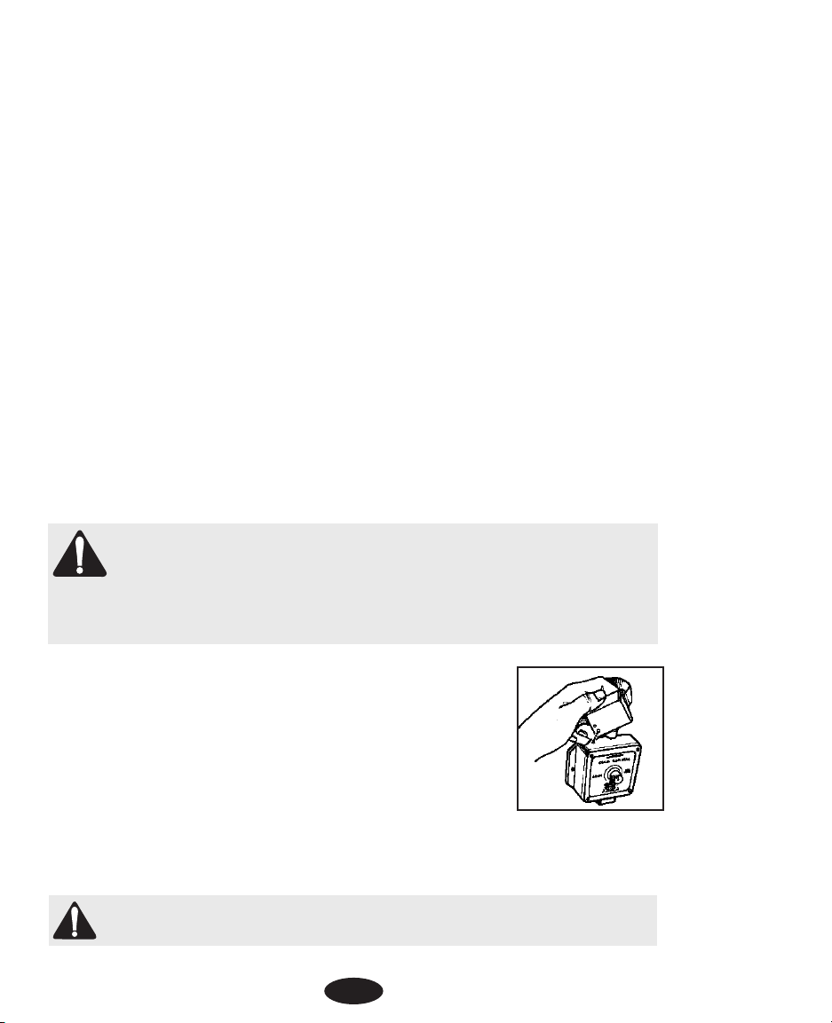
ÉTAPE 8.
VÉRIFIER SI LE TRANSMETTEUR FONCTIONNE CORRECTEMENT
Pour vérifier si le transmetteur fonctionne correctement, regardez le voyant rouge du transmetteur. Une lumière
rouge continue vous indique que le transmetteur reçoit le courant, que les deux fils sont connectés, et que le fil
forme une boucle continuelle, ininterrompue. Le voyant du transmetteur indique seulement une continuité.
Si la lumière rouge n’apparaît pas, ça signifie qu’un fil, ou que les deux, ne sont pas correctement connectés;
que les deux fils sont connectés mais que le fil est brisé; que le transmetteur ne fonctionne pas bien; ou que le
courant n’arrive pas. Corrigez le problème et recommencez le test.
ÉTAPE 9.
RÉGLER LE RÉCEPTEUR DU COLLIER
Avant de commencer, vous devez vous assurer que le système fonctionne correctement avec le récepteur du
collier.La Partie A concerne seulement un récepteur de collier rechargeable; la Partie B s’applique à un récepteur de collier fonctionnant sur pile.
A. Récepteur de collier rechargeable
Les directives suivantes s’appliquent seulement à un récepteur de collier rechargeable. Si votre récepteur de
collier fonctionne sur pile, veuillez passer à la Partie B ci-dessous.
Le récepteur du collier est chargé par le transmetteur mural. Pour charger le récepteur du collier lors de la
première utilisation, vous devez d’abord installer le transmetteur.
Le récepteur de collier rechargeable doit être chargé pendant au moins 12 heures avant que vous puissiez
l’utiliser pour la première fois. IMPORTANT! N’ENFOUISSEZ PAS LE FIL AVANT D’AVOIR TESTÉ LE SYSTÈME
AVEC VOTRE RÉCEPTEUR DE COLLIER ET D’ÊTRE SÛR QU’IL FONCTIONNE CORRECTEMENT.
REMARQUE IMPORTANTE: Le système de confinement ne fonctionne pas pendant que le récepteur du collier est en train d’être chargé. Par conséquent, vous devriez envisager a) soit de charger
le récepteur du collier seulement quand votre chien peut être surveillé ou retenu d’une autre façon;
b) soit d’acheter un autre récepteur de collier et un chargeur d’Innotek
®
et de charger un récepteur
de collier pendant que l’autre est utilisé. Pour commander un récepteur de collier et un chargeur
supplémentaires, communiquez avec le centre de service Innotek.
Pour charger le récepteur du collier:
1. Mettez le transmetteur mural en marche et placez le récepteur du collier
sur le transmetteur. Veillez à ce que La connection en relief du transmetteur s’enclenchent dans les petites encoches du fond du récepteur du collier.
2. Vérifiez si le transmetteur clignote. Ceci indique que le récepteur du collier
est en train d’être chargé. Si le transmetteur ne clignote pas, vérifiez si le
transmetteur est bien à « marche » (on) et vérifiez toutes les connexions.
3. Le voyant clignotant s’éteint lorsque le récepteur du collier est complètement chargé. Les chargeurs d’Innotek évitent automatiquement une surcharge.
4. Selon la fréquence de la correction, la charge du récepteur du collier dure généralement entre 2 et
3 semaines.
REMARQUE IMPORTANTE: Ne placez PAS le récepteur du collier sur votre chien avant que le
système de confinement n’ait été testé et que la portée du signal n’ait été ajustée.
5. Passez à l’Étape 10 ci-dessous pour tester si votre système fonctionne correctement.
35
Page 36

B. Récepteur de collier fonctionnant sur pile
Les directives qui suivent s’appliquent seulement à un récepteur de collier fonctionnant sur pile. Si votre récepteur de collier est rechargeable, veuillez consulter la Partie A ci-dessus.
Installation de la pile du récepteur de collier
1. Placez le récepteur de collier sur une surface plate, le couvercle de la pile se trouvant sur le dessus.
2. À l’aide d’une pièce de monnaie ou d’un tournevis, dévissez le couvercle du
compartiment de la pile.
3. Insérez la pile alcaline de 6 volts (incluse) dans le compartiment de la pile, le
côté positif (+) se trouvant sur le dessus.
4. Remettez le couvercle du compartiment de la pile en place. Faites attention à
ce que le couvercle soit en contact avec la pile : tournez le couvercle dans le
sens des aiguilles d’une montre jusqu’à ce qu’il soit bien fixé.
5. Selon la fréquence de la correction, la pile du récepteur de collier dure généralement entre 2 et 3
semaines.
REMARQUE IMPORTANTE: Ne placez PAS le récepteur du collier sur votre chien avant que le
système de confinement n’ait été testé et que la portée du signal n’ait été ajustée.
ÉTAPE 10.
TESTER LE SYSTÈME DE CONFINEMENT
NE TESTEZ PAS LE SYSTÈME DE CONFINEMENT LORSQUE LE RÉCEPTEUR DE COLLIER EST SUR LE CHIEN.Vous
devez tester manuellement le système de confinement pour vérifier que le signal est correctement transmis par
le fil. Utilisez le voyant témoin fourni à cet effet.
REMARQUE POUR LES SYSTÈMES RECHARGEABLES: Le système de confinement ne fonctionne pas lorsque le
récepteur du collier est en train d’être chargé sur le transmetteur.
Pour tester le système:
1. Tournez le bouton de largeur du terrain (field width) jusqu’à ce que la flèche pointe à mi-chemin
entre les positions « arrêt » (off) et « fort » (high).
2. Placez le voyant témoin sur les électrodes de façon à ce que le bout des électrodes fasse contact
avec les fils à l’intérieur des deux orifices (voir le diagramme). Appuyez doucement si nécessaire.
3. Tenez la boîte du récepteur sans toucher aux électrodes.
4. Tenez la boîte du récepteur à la hauteur du cou du chien, les électrodes
étant pointées vers le haut.
5. Faites lentement avancer le récepteur du collier vers le fil. Écoutez la tonalité d’avertissement et regardez si le voyant témoin s’allume. La lumière
devrait être faible pour une faible stimulation et brillante pour une stimulation intense.
36
Page 37
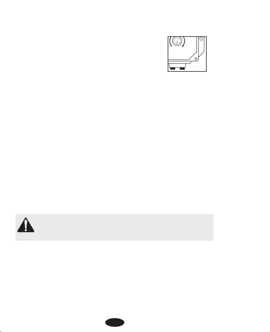
ÉTAPE 11.
RÉGLER LA PORTÉE DU SIGNAL
La zone de portée du signal est celle entre le fil et l’endroit où le récepteur du collier commence à être activé.
Le bouton de largeur du terrain (field width) règle l’ampleur de la portée du signal, non
l’intensité de la correction. En tournant le bouton dans le sens des aiguilles d’une montre, on augmente la zone de portée du signal; en le tournant dans le sens inverse des
aiguille d’une montre, on la diminue. Si on tourne complètement le bouton dans le
sens inverse des aiguilles d’une montre, le courant du transmetteur ne passe plus.
Suivez les directives de l’Étape 10 pour tester la zone de portée du signal. Faites le
tour de tout le périmètre pour vous assurer que la zone de portée du signal est constante dans l’ensemble de
la zone de confinement. La zone de portée du signal devrait s’étendre au moins à 2 mètres de chaque côté du
fil (créant un champ-barrière d’une largeur de 4 mètres). Il est préférable d’avoir un champ de 3 à 4 mètres de
largeur. Plus la zone de portée du signal est large, moins il y a de chance qu’un chien traverse cette zone.
• Si le commutateur de réglage de la superficie du terrain est réglé pour un petit terrain et que vous
ne puissiez plus tourner la portée du signal pour qu’elle soit plus large, déplacez le commutateur
au réglage pour une grande superficie de terrain. Pour savoir comment faire, regardez l’Étape 5 :
Déterminer le réglage en fonction de la superficie. Testez à nouveau le signal de largeur du terrain
(field width).
• Si le commutateur de réglage de la superficie du terrain est réglé pour un grand terrain et que vous
ne puissiez plus tourner la portée du signal pour qu’elle soit moins large, déplacez le commutateur
au réglage pour une petite superficie de terrain. Pour savoir comment faire, regardez l’Étape 5 :
Déterminer le réglage en fonction de la superficie. Testez à nouveau le signal de largeur du terrain
(field width).
Le voyant du transmetteur indique la continuité seulement. Si une borne est desserrée ou un fil entaillé, il se
peut que vous continuiez à voir une lumière rouge, ou clignotante,mais la portée du signal pourrait être réduite
ou nulle. Dans ce cas-là, ou si un fil se brise, suivez les directives de la section Dépannage qui se trouve près
de la fin de ce guide.
REMARQUE POUR LES SYSTÈMES FONCTIONNANT SUR PILE: Assurez-vous que le deuxième commutateur,
à l’intérieur du transmetteur mural, est réglé à 8.192 kHz. Ceci est le réglage fait en usine et ne devrait pas être
changé à moins d’indication contraire d’un centre de service Innotek.
REMARQUE IMPORTANTE: Si le bouton de largeur du terrain (field width) est enlevé ou que la position du bouton a été changée en le tournant dans le sens des aiguilles d’une montre, ou à l’inverse,
vous devez toujours vérifier la portée du signal pour le réglage désiré. Voir l’Étape 10 : Tester le système de confinement.
ÉTAPE 12.
INSTALLER LE FIL DE LIMITE DE TERRAIN
Outils nécessaires - bêche à bord droit, pinces à couper/dénuder les fils et tournevis standard. Si vous avez
l’intention de faire passer le fil à travers le béton, il vous faudra également un pistolet à calfeutrage, du silicone
de calfeutrage et une scie circulaire avec une lame à maçonnerie.
Mise en place du fil - Pour que le système fonctionne correctement, le fil doit être placé en une boucle continue.
Enfouissement du fil - Il n’est pas nécessaire que le fil soit enfoui, mais par mesure de protection, il est
préférable de l’enfouir au moins à 2,5 cm dans le sol. Commencez par creuser à une profondeur de 7 à 10 cm,
là où le fil commence à entrer dans le sol, près du transmetteur, et continuez autour du parcours du fil.
37
Field
Width
Page 38

Remarque : Lorsque vous entourez une grande surface, il est préférable d’utiliser une trancheuse pour creuser
dans le sol. Toutefois, nous recommandons que le fil soit placé à la main dans la tranchée. Une machine commerciale pour placer le fil pourrait le briser.
Allées de garage / Trottoir - Lorsque vous traversez une allée en asphalte, faites une coupe de 2 cm de profondeur à travers l’allée, en utilisant une scie circulaire et une lame à maçonnerie. Placez le fil dans la fente et
scellez avec un scellant à asphalte. Sur les allées de garage et les trottoirs, s’il y a un joint d’expansion, placez
simplement le fil dans le joint et scellez avec un produit de calfeutrage pour l’extérieur. Lorsque vous traversez
du gravier,enfoncez le fil au moins à 7 cm de profondeur. Utilisez un vieux boyau de jardin ou de tuyau en plastique PVC pour protéger le fil. Dans l’eau, ancrez le fil avec de grosses pierres. Protégez le fil avec un vieux
boyau de jardin ou un tuyau en plastique PVC.
ÉTAPE 13.
INSTALLER LES DRAPEAUX DE DRESSAGE
Après avoir installé le fil, testez à nouveau le système de confinement, comme décrit à l’Étape 10 : Tester le
système de confinement. Vérifiez si la zone de portée du signal est constante en suivant les instructions de l’Étape 11: Réglez la portée du signal. En même temps que vous testez à nouveau et vérifiez le système,installez
les drapeaux de dressage. Placez les drapeaux à l’endroit où vous commencez à entendre le signal d’avertissement, au moment où vous approchez du fil. Les drapeaux devraient être placés à la limite de la zone de
portée du signal, et non directement sur le fil. Ceci ajoute un signal visuel à l’avertissement sonore et aide votre
chien à reconnaître les limites.
ÉTAPE 14.
AJUSTEMENT DU COLLIER À VOTRE CHIEN
REMARQUE IMPORTANTE: Ne laissez jamais le récepteur de collier sur le chien pendant
plus de 12 heures par jour. Si vous laissez le collier sur le chien pendant plus longtemps,
sa peau pourrait s’irriter.Vérifiez périodiquement s’il n’y a pas d’irritation sur la peau du
cou du chien.
A. Électrodes
• Veillez à ce que les deux électrodes soient en contact avec la peau du chien. Au besoin, enlevez ou
amincissez une petite quantité de poils pour améliorer le contact entre l’électrode et la peau.
• Utilisez les électrodes courtes pour les chiens à poils courts. Utilisez les électrodes longues pour
les chiens dont les poils sont longs. Des électrodes spéciales sont disponibles pour les chiens au
pelage particulièrement épais. Contactez Innotek pour commander.
• Serrez les électrodes à la main, puis faites un tour supplémentaire avec la clé à électrode. Ne serrez pas trop.
• Utilisez toujours des isolants en caoutchouc entre la courroie du collier et les électrodes pour fournir
une isolation en cas d’humidité.
• Vérifiez régulièrement si les électrodes sont assez serrées pour éviter de perdre la boîte du récepteur.
38
Page 39

B. Courroie du collier
• Pour éviter une correction accidentelle à l’intérieur de la maison, enlevez le collier du cou du chien
lorsqu’il entre à l’intérieur.
• Placer le collier autour du cou du chien, la boîte du récepteur se trouvant sous le menton. Le collier doit être relativement serré pour que les électrodes entrent en contact avec la peau, sans toutefois empêcher la respiration. Vous devriez pouvoir glisser seulement un doigt sous la courroie, à
l’arrière du cou du chien.
• Assurez-vous toujours que le collier fonctionne correctement AVANT de le mettre sur le chien.
• Enlever les autres colliers de métal quand le chien porte le collier de confinement. D’autres colliers
de métal pourraient interférer dans le fonctionnement.
• Enlever le collier et couper la partie excédentaire de la courroie, en laissant 10 à 15 cm.
SECTION 2.
COMMENT FONCTIONNE LA CORRECTION
1. Tonalité d’avertissement pré-correction: Lorsque le chien arrive au bord de la zone de portée du
signal, sur le terrain, il entend un ton d’avertissement qui dure environ deux secondes. S’il ne
retourne pas dans la partie sûre du terrain, il recevra une correction continuelle jusqu’à ce qu’il
revienne à la zone de sécurité.
2. Prévention du franchissement de la limite: Le récepteur augmente automatiquement la correction
lorsque le chien avance dans la zone de portée du signal. Le chien ne peut pas « franchir » la zone
de portée du signal sans activer une forte correction.
3. Prévention d’une correction excessive: Dans le cas peu probable où le chien se ferait « attraper »
dans la zone de portée du signal, le système s’arrêterait après 10 secondes avant de recommencer
la correction pour 20 autres secondes. Ce schéma alterne jusqu’à ce que le chien revienne dans la
zone de sécurité ou que le système soit arrêté.
SECTION 3.
DRESSAGE DE VOTRE CHIEN
Pour retirer le maximum de votre système de confinement pendant le dressage, gardez ces conseils à l’esprit:
• Pour éviter une correction accidentelle à l’intérieur de la maison, enlevez le collier du cou du chien
lorsqu’il entre à l’intérieur.
• Assurez-vous toujours que le collier fonctionne correctement AVANT de le mettre sur le chien.
Vérifiez si le système fonctionne correctement et si la largeur du terrain (field width) est appropriée,
telle que décrite dans la Section 1, Étape 11 : Régler la portée du signal.
• Demeurez positif et jouez avec le chien pendant la séance de dressage.
• Les séances de dressage doivent être brèves. Ne continuez jamais une séance de dressage si le
chien ne montre plus aucun intérêt. Arrêtez-vous pour qu’il se repose ou qu’il joue.
• Complimentez TOUJOURS votre chien pour s’être bien comporté.
39
Page 40

Les étapes suivantes montrent comment effectuer un dressage réussi:
ÉTAPE 1.
DRAPEAUX DE DRESSAGE
1. Tournez le transmetteur mural à « arrêt » (off) de façon à ce qu’aucune correction ne soit donnée
à votre chien.
2. Mettez le récepteur de collier sur votre chien.
3. Accrochez votre chien à une longue laisse. Jouez avec lui dans la zone de sécurité du terrain pendant 2 à 4 minutes. Ne laissez pas votre chien courir librement ni traverser les lignes de drapeaux.
4. Avancez vers les drapeaux. Lorsque vous arrivez à un drapeau, secouez-le. Dites « mauvais drapeau » d’un ton désapprobateur.
5. Retournez à la partie centrale du terrain et jouez avec votre chien. Récompensez-le avec une
gâterie.
6. Répétez cet exercice plusieurs fois dans divers endroits du terrain.
ÉTAPE 2.
LA PREMIÈRE CORRECTION
1. Vous devez régler à nouveau la portée du signal avant de placer le récepteur de collier sur votre
chien. Suivez les instructions données à la Section 1, Étape 11: Régler la portée du signal.
2. Mettez le récepteur de collier sur votre chien dans la zone de sécurité du terrain.
3. Accrochez votre chien à une longue laisse. Jouez avec lui dans la zone de sécurité du terrain.
4. Avancez vers les drapeaux. Si votre chien essaie d’éviter les drapeaux, félicitez-le et rassurez-le.
5. Répétez cette étape dans d’autres endroits du terrain.
6. Ne donnez pas plus de trois corrections par jour, ou sept par semaine. Ceci dépend de la tolérance
de votre chien au stress. La plupart des chiens reçoivent seulement quelques corrections pendant
la phase de dressage; ils répondent très rapidement à la tonalité.
7. Récompensez votre chien lorsqu’il évite les drapeaux, même s’il reçoit une correction.
8. Jouez avec votre chien dans la zone de sécurité avant de terminer cette session de dressage.
ÉTAPE 3.
ESSAI AVEC LAISSE
1. Le collier étant sur votre chien et le transmetteur mural en « marche » (on), jouez avec votre chien
(en laisse) dans la zone de sécurité. Après quelques minutes de jeu,envoyez un jouet ou une gâterie
à travers les drapeaux.
2. Si votre chien court à travers les drapeaux pour aller chercher le jouet, attendez la réaction de sursaut et tirez votre chien vers l’arrière dans la zone de sécurité. Félicitez votre chien et récompensez-le.
3. Renforcez le dressage en secouant un drapeau. Dites « mauvais drapeau » d’un ton désapprobateur. Envisagez d’augmenter la portée du signal. Pour cela, enlevez le collier de votre chien, augmentez la portée du signal, et refaites le test. Référez-vous à la Section 1,Étape 11: Régler la portée
du signal.
4. Répétez cet exercice dans d’autres endroits du terrain.
5. Félicitez votre chien lorsqu’il évite les drapeaux. Demeurez positif et jouez avec le chien pendant
la séance de dressage.
6. Lorsque votre chien refuse de courir à travers les drapeaux 20 fois consécutives, passez à l’étape suivante.
40
Page 41

ÉTAPE 4.
ESSAI SANS LAISSE
1. Suivez les instructions de l’Étape 3 : Essai avec laisse, mais cette fois laissez tomber la laisse sur
le sol. Elle sera là si vous avez besoin de rattraper votre chien.
2. Si votre chien traverse la zone de portée du signal pendant cette phase, enlevez rapidement le collier. Ramenez votre chien dans la zone de sécurité. Remettez le collier sur votre chien. Renforcez
le dressage « mauvais drapeau ». Félicitez votre chien et récompensez-le.
3. Répétez ce dressage sans laisse jusqu’à ce que vous soyez certain que votre chien ignore les tentations qui se trouvent en dehors de la zone de confinement.
SECTION 4.
CONSEILS D’ENTRETIEN DU SYSTÈME
Votre système nécessite très peu d’entretien. Le récepteur de collier fonctionnant sur pile est résistant à l’eau
et ne devrait pas être immergé dans quelque liquide que ce soit. Ceci provoquerait des dommages qui ne sont
pas couverts par la garantie du fabricant. Le collier rechargeable est étanche et continuera à fonctionner après
avoir été immergé dans l’eau. Pour enlever la saleté,passez simplement un chiffon mouillé avec de l’eau savonneuse. Ne placez jamais le collier dans un lave-vaisselle.
Le transmetteur mural n’est pas étanche et doit être protégé des intempéries. Si la foudre frappe à proximité,
l’unité pourrait être endommagée. Débranchez le transmetteur et déconnectez les fils pendant les orages.
N’essayez pas de démonter ou de réparer des composants du système; ceci annulerait la garantie du fabricant.
Ces composants contiennent des circuits informatisés qui doivent être réparés seulement par un expert agréé.
Testez le système une fois par semaine pour vous assurer que le récepteur du collier fonctionne correctement.
En testant le système, vérifiez aussi si le réglage de la largeur du terrain (field width) est correct. Pour cela,
attachez le voyant témoin fourni aux électrodes du récepteur de collier.En tenant le récepteur par le boîtier, PAS
par les électrodes, marchez vers la zone de portée du signal. Écoutez la tonalité d’avertissement et regardez si
le voyant témoin s’allume.
REMARQUE POUR LES SYSTÈMES RECHARGEABLES:
Tous les six mois,le récepteur du collier devrait être déchargé complètement puis rechargé. Pour décharger le
récepteur,mettez le système en marche et placez le récepteur du collier, en y attachant le voyant témoin, dans
la zone de portée du signal. Lorsque le récepteur arrête d’émettre une tonalité et que le voyant témoin s’éteint,
il est totalement déchargé. Utilisez toujours le voyant témoin lorsque vous déchargez le récepteur du collier. Si
vous ne le faites pas, vous pourriez endommager le récepteur du collier de façon permanente.
SECTION 5.
GUIDE DE DÉPANNAGE
A. Le chien ne répond pas à la correction:
• Ajustez le collier.
• Coupez les poils du chien ou utilisez des électrodes plus longues pour améliorer le contact avec la
peau.
• Changez ou rechargez la pile dans le récepteur du collier.
41
Page 42

• Assurez-vous que la bride de connexion du transmetteur mural est réglée à 8.192 kHz. (Système
de receveur fonctionnant sur pile seulement).
Pour de plus amples renseignements, visitez notre site Web à www.innotek.net.
REMARQUE POUR LES SYSTÈMES RECHARGEABLES SEULEMENT:
Si votre chien ne répond pas à la correction, le système rechargeable permet de régler le niveau
de correction sur le transmetteur mural à faible (low) moyen (medium) ou fort (high). Le
réglage fait à l’usine est à moyen. Si vous voulez changer le niveau :
1. Tournez le bouton de largeur du terrain (field width) à la position « arrêt » (off).
Enlevez le bouton, les quatre vis du couvercle et le couvercle frontal.
2. Le commutateur, dans le coin supérieur droit du transmetteur,
peut être déplacé vers la droite pour le réglage faible (low) ou
être complètement enlevé pour le réglage fort (high).
3. Remettez le couvercle du transmetteur et les quatre vis du couvercle en place.
4. Tournez le bouton pour que le pointeur soit en position « arrêt »
(off).
5. Testez à nouveau la portée du signal comme décrit à l’Étape 10.
REMARQUE: Si le transmetteur est réglé à fort (high), il n’y aura
pas de tonalité d’avertissement pré-correction.
B. Procédé de vérification du système:
Si le système fonctionne mal, vous devez faire une boucle d’essai pour déterminer quelle composante - collier,
transmetteur mural ou fil du terrain – ne fonctionne pas correctement. Pour effectuer la boucle d’essai,
procédez comme suit:
1. Faites une boucle d’essai en utilisant un morceau de fil d’au
moins 4 mètres de longueur.
2. Enlevez le fil existant de votre transmetteur mural.
3. Insérez les deux extrémités du fil de la boucle d’essai dans le
transmetteur mural.
4. Tournez le bouton de largeur du terrain (field width) en position
9 h, ou en réglage faible (low).
5. Placez le voyant témoin sur le récepteur du collier. En tenant le
collier dans la main, déplacez-vous à l’extérieur de la zone et
approchez la boucle d’essai. Prenez mentalement note de la distance entre le collier et le fil quand le collier est activé.
6. Tournez le bouton de largeur du terrain (field width) à la position
12 h ou au réglage moyen (medium).
7. Éloignez-vous du fil et approchez-vous à nouveau. Déterminez la distance, entre le collier et le fil,
à laquelle le collier est activé. La distance devrait être supérieure lorsque le réglage est à moyen
(medium).
8. Si plus d’un récepteur de collier est utilisé avec le système, répétez le test ci-dessus avec chacun
des colliers.
42
INDICATOR LIGHT
SMART DOG
Field
Width
Page 43

Résultats du test:
Si aucune lumière rouge ne s’allume sur le transmetteur mural lorsque le fil de boucle d’essai est en place,
c’est le transmetteur mural qui fonctionne mal.
Si la lumière rouge est allumée de façon constante sur le transmetteur mural, mais que le collier n’est pas activé
sur le fil de la boucle d’essai, c’est le récepteur du collier qui ne fonctionne pas. Changez ou rechargez la pile
du récepteur du collier et recommencez le test.
Si la lumière rouge est allumée de façon constante sur le transmetteur mural et que le récepteur du collier s’active lorsque vous vous approchez du fil de la boucle d’essai, c’est le fil de limite du terrain qui est la cause du
problème.
C. Pour localiser l’endroit où le fil est cassé:
Pour localiser l’endroit où le fil est cassé dans une installation en boucle, utilisez un dispositif à cet effet qui
s’appelle un « RF- Choke ». Vous en trouverez chez RadioShack® (no 273-102C du catalogue). Une fois que
vous aurez ce dispositif, faites ce qui suit:
1. Déconnectez le courant en débranchant l’adaptateur de la prise.
2. Déconnectez les fils du transmetteur mural.
3. Courbez les plombs du « RF-Choke » pour leur donner la forme
d’un fer à cheval.
4. Entourez doucement les extrémités du fil (dénudé) autour des
plombs du « RF-Choke » (un de chaque côté).
5. Branchez les plombs du « RF-Choke » dans les bornes du trans-
metteur.
6. Branchez l’adaptateur dans la prise.
7. Réglez une radio portative AM à une fréquence d’environ 600 kHz.
8. Réglez le bouton de largeur du terrain (field width) suffisamment haut pour obtenir un signal sur
la radio portative lorsque vous tenez la radio au-dessus du fil de confinement.
9. Le signal devrait être absent sur la partie de fil tortillé parce que la torsade annule le signal.
Lorsque vous atteignez la zone de limite de terrain où il y a un seul fil, écoutez la statique pulsative à la radio.
10. Tenez la radio à la hauteur de la poitrine et faites-la balancer au-dessus du fil en marchant tout
le long de la limite de terrain.
11. Si la tonalité s’arrête, faiblit ou change de rythme, marquez l’endroit avec un drapeau ou un
bâton. S’il n’y a aucun son, c’est que le fil est complètement cassé. Si le signal s’affaiblit ou
change de rythme, regardez s’il y a une entaille dans l’isolation.
12. Continuez à suivre la limite de terrain et marquez chaque changement de signal par un drapeau
ou un bâton.
13. Après avoir fait tout le tour de la limite de terrain, retournez aux endroits marqués. Examinez le
fil sur ca. 1 m dans chaque direction.
14. Remplacez le fil endommagé en prenant un fil de même calibre que dans l’installation originale
et utilisez des raccords étanches pour faire la connexion.
Pour de plus amples renseignements, visitez notre site Web à www.innotek.net.
43
Page 44

GARANTIE INTERNATIONALE LIMITÉE
INNOTEK®garantit à l’acheteur d’origine les produits de la marque INNOTEK contre les défauts de matériaux et les
vices de fabrication, dans le cadre d’une utilisation normale, pendant une période de deux ans à partir de la date
d’achat au détail initiale. Cette garantie limitée exclut les dommages accidentels provenant de mâchonnement ;
les dommages causés par la foudre lorsqu'un composant INNOTEK contre la foudre n’est pas utilisé (pour les systèmes de délimitation enterrés) ; la négligence, l’altération et les utilisations abusives.
INNOTEK offre plusieurs options d’échange de produits pendant la période de garantie. Si des réparations s’avèrent
nécessaires, appelez votre centre de service après-vente agréé INNOTEK pour discuter de la modalité de service
après-vente qui correspond le mieux à vos besoins. Les coûts sont liés au temps de traitement et aux options d’expédition. Veuillez ne pas retourner ce produit à votre revendeur.
Une fois la période de deux ans après la date d'achat initial écoulée, nous réparerons, remplacerons ou mettrons
à niveau votre produit selon un tarif fixe établi sur la base des composants.
INNOTEK, Inc. décline toute responsabilité en cas de dommages indirects ou accessoires provenant de l'utilisation
du produit ou causés par tout défaut, toute défaillance ou tout dysfonctionnement du produit, que la réclamation
soit basée sur la garantie, un contrat, une négligence ou autre.
Les produits de INNOTEK ne sont pas des substituts au dressage à l'obéissance traditionnel. INNOTEK ne
garantit pas l’efficacité de son produit en raison des variations de personnalité des chiens, de leur tempérament, et des influences sur lesquelles INNOTEK n’a aucun contrôle.
Pour toute réparation, veuillez communiquer avec le Centre de service le plus près de chez vous, dont vous
trouverez les coordonnées ci-dessous, pour obtenir un numéro d’autorisation de retour de marchandise
(ARM) et des instructions pour le retour. Si la demande de retour est approuvée, veuillez faire parvenir les
pièces défectueuses, ou le système au complet, en envoi assuré, à l’adresse spécifiée. Les frais de port ne
sont pas couverts.
Innotek est une marque de Innotek, Inc.
Tous les autres noms de produits ou de services sont la propriété de leur détenteurs respectifs.
© 2005 Innotek, Inc. Tous droits réservés.
1000 Fuller Drive, Garrett, IN,USA 46738
www.innotek.net
Page 45

Eingrenzanlage
Bedienungsanleitung
Das Funkhalsband von Innotek®gehört zu den sichersten,
humansten und effektivsten Ausbildungseinrichtungen auf dem
Markt. Bei zweckmäßigem Einsatz bietet der elektronische Reiz
eine Ablenkung, welche der Hund als unangenehm empfinden wird.
Ein gehorsamer Hund lernt verhältnismäßig schnell den Reiz
auszuschalten und Vertrauen zu gewinnen. Wie die meisten
Produkte von Innotek, hat das Funkhalsband einstellbare
Stimulationsstufen. In dieser Weise kann die Reizwirkung an das
Temperament des Tieres angepasst werden.
Achtung
Bitte haben Sie etwas Geduld und lesen Sie die Bedienungsanleitung vor dem ersten Gebrauch. Hier finden Sie
Angaben über wichtige Voreinstellungen, die zur erfolgreichen Ausbildung von Wichtigkeit sind. Beachten Sie
bitte die folgenden Regeln:
• Das Funkhalsband ist nur für den Gebrauch mit Hunden bestimmt.
• Viele Hundebesitzer sind überrascht, wie viel mit äußerst geringer Stimulation erreicht werden kann
- verwenden Sie daher die geringste Stimulation, die zur Erzielung des gewünschten Verhaltens
erforderlich ist.
• Verbrauchte oder entladene Batterien führen zu unzuverlässigem Betrieb. Verwenden Sie das Gerät
nur bei voller Batteriespannung, d.h. mit frischen, vollaufgeladenen Batterien.
• Geben Sie Ihrem Hund im Anfang Gelegenheit sich an das Halsband zu gewöhnen. Der Hund muss
das Funkhalsband als Bestandteil der Ausbildung sehen und nicht als Korrekturmittel.
• Der Hund sollte das Funkhalsband niemals länger als 12 Stunden pro Tag tragen.
• Niemals Einstellungen vornehmen, während der Hund das Halsband trägt.
• Ein Funkhalsband sollte nur unter sorgfältiger Überwachung durch den Hundebesitzer verwendet
werden.
• Achtung: Von Kindern fern halten.
• Alle Anweisungen vor Gebrauch lesen. Bei weiteren Fragen wenden Sie sich bitte an den zuständigen Fachhändler oder Innotek-Kundendienst.
Wichtig
Denken Sie daran, dass jeder Hund anders geartet ist und dass Sie nicht wissen können, wie Ihr Hund auf
dieses Produkt reagieren wird. Zur Gewährleistung der Sicherheit Ihres Hundes sollte die anfängliche
Ausbildung mit Hilfe einer langen Leine erfolgen, um die Situation stets unter Kontrolle zu behalten. Sie sollten
weiterhin wissen, dass sich ein aggressives Tier nach Erhalten der Stimulation gegen den Hundeführer wenden
könnte. Wenn Sie daher der Meinung sind, dass Ihr Hund ein aggressives Verhalten aufweist oder sich in der
Vergangenheit aggressiv gezeigt hat, sollten Sie vor der Verwendung dieses Produkts eine Fachkraft im Bereich
Tierverhalten zu Rate ziehen. Siehe in Abschnitt 3 auf Seite 54 Die Ausbildung Ihres Hundes.
Funktionsweise
Das Abgrenzkabel ist am Sendegerät angeschlossen, welches über ein Steckernetzteil versorgt wird.Wird die
Anlage eingeschaltet, so wird ein Funksignal vom Abgrenzkabel ausgestrahlt.Wenn sich der Hund dem Kabel
nähert wird vom Funkhalsband ein kurzfristiger aber harmloser Strafreiz als Korrekturmittel ausgelöst. Der Hund
45
Ne Onzichtbare omheining 15
Fr Guide d’emploi 30
De Bedienungsanleitung 45
It Guida di funzionamento 60
Es Guia de Funcionamiento 75
Page 46

versucht natürlich vom Kabel Abstand zu halten und lernt äußerst schnell, sich innerhalb der bestehenden
Grenzen zu bewegen.
Abschnitt 1.
Anleitung zum Einstellen der Eingrenzanlage
Diese Bedienungsanleitung ist für Funkhalsbandmodelle für Batterie- sowie auch für Akkubetrieb bestimmt.An
gewissen Stellen in der Bedienanleitung finden Sie besondere Hinweise auf diese Modelle.
Punkt 1
Auslegung der einzufassenden Fläche
A. Lageplan ausarbeiten und Zeichnung erstellen
Sie sollten einen Lageplan für den Auslauf Ihres Hundes ausarbeiten. Eine Zeichnung hilft unverhoffte
Hindernisse zu vermeiden. Die Zeichnung sollte die genaue Lage von Haus, Fahrweg, Garten, Gartenteich, Pool,
usw. veranschaulichen. Das Gleiche gilt für den Kabelverlauf einer eventuellen Eingrenzanlage auf dem
Nachbargrundstück.
B. Die städtischen Versorgungswerke benachrichtigen
Benachrichtigen Sie die städtischen Versorgungswerke, und lassen Sie alle unterirdischen
Versorgungsleitungen (Gas, Wasser, Strom, Telefon, TV) markieren. Alle unter der Erde befindlichen Leitungen
sollten in der Zeichnung eingetragen werden, denn der spätere Kabelverlauf hängt von der Lage solcher
Leitungen ab.
C. Aufstellpunkt des Sendegeräts festlegen
Das Sendegerät kann mit Hilfe der mitgelieferten Schrauben an der Wand im Bereich einer 220–Volt
Netzsteckdose montiert werden. Obwohl das Gerät widerstandsfähig ist gegen Frost,es ist nicht wasserdicht –
deshalb ist ein eingeschlossener Raum besser für das Sendegerät geeignet.
Hinweis für Akkubetrieb: Die Umgebungstemperaturen für das Sendegerät sollten zwischen 0° und 45°C
liegen.
D. Verlegung der Abgrenzkabel vom Ausgang zum Abgrenzgebiet
In Hinsicht auf den von Wettereinflüssen geschützten Aufstellort, sollte man überlegen, wie das Kabel am besten
vom Sendegerät nach außen verlegt werden soll. Vorhandene Öffnungen, wie z.B. Fenster, Türen oder andere
Versorgungsdurchgänge, bieten leichten Zugang nach außen. Mitunter muss ein Loch durch die Außenwand
gebohrt werden.
Punkt 2
Geplanten Kabelverlauf auf die Zeichnung übertragen
Tragen Sie den geplanten Kabelverlauf ebenfalls in der Zeichnung ein. Das erleichtert die Arbeit später bei der
Kabelmontage.
46
Page 47

Zur ordnungsgemäßen Funktion der Anlage muss das Kabel eine ununterbrochene Schleife bilden. Das Signal
verläuft von einer der Anschlussklemmen am Sendegerät durch das Kabel und wieder zurück zur gegenüberliegenden Anschlussklemme.
Wichtige Hinweise zur Kabelverlegung:
• Die Kabelschleife nicht näher als 2 m parallel zu anderen auf dem Grundstück befindlichen Versorgungskabeln, wie z.B. Netzstrom, Telefon oder Fernsehen, verlegen.
• Einzelne Kabelabschnitte nicht näher als 3 m zueinander verlegen, sonst können sich die
Signale gegeneinander aufheben.
• Das Abgrenzkabel nicht näher als 3 m von anderen Eingrenzanlagen verlegen.
Punkt 3
Die erforderliche Drahtlänge abschätzen
Die Modelle für Batterie– sowie Akkubetrieb schließen 152 m Kabel im Lieferumfang ein, genügend für eine
Fläche von fast 0,2 ha.
Die erforderliche Kabellänge hängt von mehreren Faktoren ab:
(a)Gesamte abzugrenzende Fläche
(b)Verlegung einer Doppelschleife. Hier ist doppelt soviel Kabel
erforderlich.
(c)Bereich des Signalfeldes. Das Signalfeld ist der Abstand zwischen
dem Kabel und dem Punkt an dem das Funkhalsband zuerst
reagiert. Ein Feld von 3 bis 4 m wird empfohlen.
Das Abgrenzkabel lässt sich mit weiteren Nachrüstsätzen (separat erhältlich) verlängern um eine
größere Fläche einzuschließen. Das batteriebetriebene Modell kann bis zu 2 ha und das Akkumodel bis zu 10
ha einschließen. Der komplette Bausatz besteht aus 152 m Kabel, 50 Markierungsfähnchen und zwei
wasserdichten Kabelverbindern.
Punkt 4
Das Sendegerät an der Wand anmontieren
Das Sendegerät an der Wand in unmittelbarer Nähe einer 220–Volt Netzsteckdose anmontieren. Den
Netzstecker erst an der Steckdose anschließen, nachdem das Abgrenzkabel verlegt ist.
47
Eingegrenzter Hinterhof
mit Hintertürzugang
Hund aus einem bestimmten
Gebiet fernhalten
Beispielweiser Verlegungsplan
Gesamtes Grundstück
eingegrenzt mit
Gebietsschutz
Page 48

Punkt 5
Die Größe der Auslauffläche ermitteln
Im Innern des Sendegeräts befindet sich eine
Schaltbrücke mit zwei Steckpositionen, die sich auf
kleine oder große Grundstücksflächen einstellen
lässt. Die werksseitige Einstellung ist für kleine
Grundstücke, ausreichend für Kabellängen bis zu
300 m. Die Einstellung für große Grundstücke ist für
Kabellängen über 300 m bestimmt.
Die Grundstücksfläche wird wie folgt umgestellt:
1. Den Knopf Signalreichweite (Field Width) auf AUS (off) drehen.
2. Den Knopf sowie die vier Befestigungsschrauben am Deckel
abnehmen.
3. Je nach Grundstücksfläche die gewünschte Steckposition
wählen. Das Sendegerät funktioniert nicht ohne die
Schaltbrücke.
• Wichtig für Akkubetrieb: Die Schaltbrücke befindet sich
unten links am Sendegerät. „SM" ist für kleine und „LG"
für große Grundstücksflächen bestimmt (siehe Bild 1).
• Wichtig für Batteriebetrieb: Die Schaltbrücke
befindet sich rechts am Sendegerät. Die Steckposition
„SMALL" ist für kleine und „LARGE" für große
Grundstücksflächen bestimmt. Eine zweite Schaltbrücke ist
mit „DUAL FREQ" (zwei Frequenzbereiche) und „8.192 kHz"
beschriftet. Diese Schaltbrücke sollte auf 8.192 kHz stehen
und nur auf Anweisung vom Innetek–Kundendienst
umgesteckt werden (siehe Bild 2).
4. Den Deckel mit Hilfe der vier Schrauben wieder am
Sendegerät anbringen.
5. Den Knopf Signalreichweite (Field Width) mit dem Zeiger auf
AUS (Off) wieder anmontieren.
Punkt 6
Ausrollen des Abgrenzkabels
Wichtiger Hinweis: Bevor das Kabel unter der Erde verlegt wird, die Anlage zuerst einer
Funktionsprüfung unterziehen. Beim Verlegen darauf achten, den Kabelmantel nicht zu beschädigen.
Bild 1
Gerät für Akkubetrieb
Bild 2
Gerät für Batteriebetrieb
48
Kontaktstift zum Aufladen –
(Akkumodell) Anzeigelampe
Feldweite
Stromanschluss
Anschlussklemmen
Abweichungen im Aussehen des Sendegeräts
von der Veranschaulichung sind möglich
INDICATOR LIGHT
Field
Width
SM LG
SM LG
SM LG
MED LO
Page 49
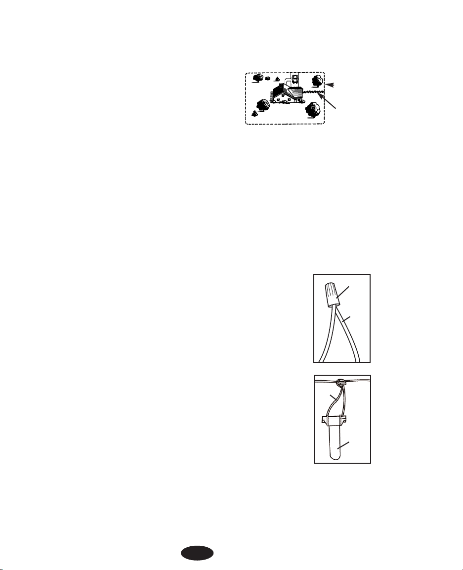
1. Die Zeichnung soll hier als Arbeitsunterlage dienen. Das Kabel der Grenze entlang auslegen,
sodass es die einzuschließende Fläche in einer ununterbrochene Schleife umkreist. Das Kabel an
den Ecken im gleichmäßigen Bogen, mit einem Radius von nicht weniger als 1 m auslegen.
Dadurch wird ein gleichmäßigeres Signalfeld erzielt.
2. Sollte das mitgelieferte Kabel nicht ausreichen, so muss die
Spleißung zwischen einzelnen Kabellängen wasserdicht
ausgeführt werden. Stets nur die mitgelieferten oder gleichwertige Kabelverbinder verwenden. Isolierband oder
Schraubdrahtverbinder führen zu unzuverlässigem Betrieb
oder zum Versagen der Anlage und sollten niemals verwendet werden.
3. Die Verlegung der Grenze entlang fortsetzen, bis der Anfang
der Schleife erreicht ist.
4. Das Kabelende abschneiden.
Punkt 7
Abgrenzkabel am Sendegerät anschließen
Die Zuleitung vom Abgrenzkabel zum Sendegerät, sollte verdrillt sein, um mögliche Signalausstrahlungen
aufzuheben. In dieser Weise kann das Tier diesen Bereich ohne Korrektur betreten. Durch Verdrillen werden
weiterhin Störungen durch andere Leitungsdrähte aufgehoben.
1. Den Abstand vom Sendegerät zum Abgrenzkabel messen.
2. Den gemessenen Abstand mit 1,5 multiplizieren, weil sich der Leitungsdraht
beim Verdrillen verkürzt.
3. Zwei Leitungsdrähte auf die ermittelte Länge abschneiden.
4. Die beiden Leitungsenden nebeneinander halten und verdrillen. Die Drähte kön-
nen entweder von Hand oder mit Hilfe einer elektrischen Bohrmaschine verdrillt
werden, bis die Drehungen einen Abstand von etwa 6 bis 12 cm erreichen. Je
fester die Leitungen verdrillt sind, umso besser ist die Signalaufhebung.
5. Ein Ende der verdrillten Leitung von einer Seite in den Kabelverbinder einführen.
Den Leitungsdraht NICHT vor Einführen in die Öffnung abisolieren. Ein Ende des
Abgrenzkabels in das entgegengesetzte Ende des Kabelverbinders einführen.
Das schwarze Oberteil des Kabelverbinder mit einer Zange zusammendrücken.
6. Punkt 5 wiederholen um das zweite Ende der verdrillten Leitung mit dem ent-
gegengesetzten Ende des Abgrenzkabels zu verbinden. Eine Öffnung am
Kabelverbinder bleibt frei.
7. Die verdrillte Leitung durch eine vorhandene Öffnung oder ein Bohrloch führen,
um dieselbe am Sendegerät anzuschließen.
8. Von jedem Ende der verdrillten Leitung etwa 1 cm abisolieren.
9. Die Leitungsdrähte in die Anschlussklemmen am Sendegerät einführen.
10. Das Steckernetzgerät an einer normalen 220-Volt-Netzsteckdose anschließen.
11. Das Kabel vom Steckernetzgerät am Stromeingang des Sendegeräts anschließen.
49
Sendegerät an der
Garagenwand
Abgrenzkabel
Verdrillte
Leitung zum
Sendegerät
Verlegungsplan
Wire
Gel-filled
capsule
Wire nut
Wire
Page 50

Punkt 8
Die Funktionsfähigkeit des Sendegeräts überprüfen
Achten Sie auf das rote Anzeigelicht um die Funktionsfähigkeit des Sendegeräts zu prüfen. Ein ständig aufleuchtendes Anzeigelicht bedeutet, dass das Sendegerät mit Strom versorgt ist, das beide Leitungsdrähte
angeschlossen sind und eine ununterbrochene Schleife bilden.
Nichtaufleuchten des Anzeigelichts bedeutet, dass eines oder beide der Leitungsdrähte nicht ordnungsgemäß
angeschlossen sind, dass ein Fehler im Sendegerät aufgetreten ist oder der Strom abgeschaltet wurde. Die
entsprechenden Maßnahmen unternehmen und wiederholt prüfen.
Punkt 9
Einstellen des Funkhalsbandempfängers
Bevor Sie fortfahren, müssen Sie dafür sorgen, dass die Anlage zusammen mit dem Funkhalsband voll funktionsfähig ist. Abschnitt A bezieht sich auf Funkhalsbandempfänger für Akkubetrieb und Abschnitt B für
Batteriebetrieb.
A. Funkhalsband für Akkubetrieb
Die folgenden Anweisungen beziehen sich ausschließlich auf Funkhalsbandempfänger für Akkubetrieb.
Anweisungen für Akkubetrieb finden Sie in Abschnitt B weiter unten.
Das Funkhalsband wird über das an der Wand hängende Sendegerät aufgeladen.Um das Funkhalsband für den
erstmaligen Gebrauch aufzuladen, muss zuerst das Sendegerät installiert werden. Bei Akkubetrieb muss das
Funkhalsband vor dem ersten Gebrauch mindestens für 12 Stunden aufgeladen werden. Wichtig! Das Kabel erst
dann unterirdisch verlegen, nachdem die Anlage mit dem Funkhalsband auf Funktionsfähigkeit geprüft wurde.
Wichtiger Hinweis: Die Anlage ist nicht funktionsbereit, solange das Funkhalsband aufgeladen
wird. Es bestehen hier zwei Möglichkeiten. Sie können das Funkhalsband aufladen, während Sie
Ihren Vierbeiner z.B. an der Leine ausführen oder im Haus einschließen. Sie können ein weiteres
Funkhalsband nebst Ladegerät durch Innotek beziehen und eines aufladen, während das andere in
Gebrauch ist. Weitere Funkhalsbandempfänger und Ladegeräte erhalten Sie durch Ihren Innotek
Fachhändler.
Aufladen des Funkhalsbandempfängers:
1. Das Sendegerät einschalten und das Funkhalsband darauf legen. Dabei
den hervorstehenden Metallstift am Sendegerät in die Einbuchtung unten
am Halsband einführen.
2. Die Blinkanzeige am Sendegerät bedeutet, dass das Funkhalsband aufgeladen wird. Bei Nichtaufleuchten der Blinkanzeige nachprüfen, ob das
Sendegerät eingeschaltet ist und ob alle Anschlussverbindungen fest
angezogen sind.
3. Die Blinkanzeige erlischt, nachdem das Funkhalsband voll aufgeladen ist. Das Innotek™ Ladegerät
verhindert automatisch Ladeüberschreitungen.
4. Die Batterie im Funkhalsband, je nach Häufigkeit der Korrekturmaßnamen,sollte für 2 bis 3 Wochen
ausreichen.
Wichtiger Hinweis: Das Funkhalsband darf erst nach Prüfen der Anlage und nach
Einstellen der Signalstärke an Tieren verwendet werden.
5. Zum Überprüfen der Anlage mit Punkt 10 weiter unten fortfahren.
50
Page 51

B. Funkhalsband für Batteriebetrieb
Die folgenden Anweisungen beziehen sich ausschließlich auf Funkhalsbandempfänger für Batteriebetrieb.
Anweisungen für Akkubetrieb finden Sie in Abschnitt A weiter oben.
Einbau der Batterie im Funkhalsband
1. Das Funkhalsband mit dem Batteriedeckel nach oben auf eine ebene Fläche
legen.
2. Den Deckel zum Batteriefach mit Hilfe einer Münze oder einem Schraubendreher abschrauben.
3. Eine Alkali –Batterie von 6 Volt (einbegriffen) mit dem Pluspol nach oben in das Batteriefach einsetzen.
4. Den Batteriefachdeckel wieder im Uhrzeigersinn anschrauben und darauf achten, dass der Deckel
mit der Batterie in Kontakt bleibt.
5. Die Batterie im Funkhalsband, je nach Häufigkeit der Korrekturmaßnamen,sollte für 2 bis 3 Wochen
ausreichen.
Wichtiger Hinweis: Das Funkhalsband darf erst nach Prüfen der Anlage und nach Einstellen der
Signalstärke an Tieren verwendet werden.
Punkt 10
Überprüfen der Anlage
Die Anlage niemals überprüfen, während das Tier das Funkhalsband trägt. Die gesamte Anlage muss manuell
auf die funktionsgerechte Ausstrahlung des Funksignals durch das Abgrenzkabel geprüft werden. Dazu dient
die mitgelieferte Prüflampe.
Hinweis für Akkubetrieb: Die Anlage ist nicht funktionsbereit, solange das Funkhalsband vom Sendegerät
aufgeladen wird.
Die Anlage wie folgt prüfen:
1. Den Knopf Signalreichweite (Field Width) so drehen, bis der Pfeil auf die
Mittelstellung zwischen Aus (off) und Max (high) gerichtet ist.
2. Die Prüflampe derart an den Kontaktstiften anordnen, sodass die Kontakte
mit den Leitungsdrähten innerhalb der Öffnungen (siehe Bild) in Berührung
kommen. Ein leichter Druck hilft dabei.
3. Den Funkhalsbandempfänger in der Hand halten, ohne dabei die
Kontaktstifte zu berühren.
4. Den Empfänger mit den Kontaktstiften nach oben gerichtet in Halshöhe des Hundes tragen.
5. Langsam mit dem Empfänger in Richtung Abgrenzkabel schreiten. Dabei warten, bis ein Warnton
zu hören ist und die Prüflampe aufleuchtet. Bei schwacher Stimulation leuchtet die Prüflampe nur
schwach auf, aber bei starker Stimulation leuchtet sie hell auf.
51
Page 52

Punkt 11
Einstellen der Signalreichweite
Die Signalreichweite ist der Abstand vom Kabel zu der Stelle, wo das Funkhalsband
zuerst anspricht. Mit dem Knopf Signalreichweite (Field Width) wird die Signalreichweite
entlang der Eingrenzung eingestellt, aber nicht die Stärke der Korrektur. Drehen nach
rechts erhöht die Reichweite, Drehen nach links verringert sie. Bei völliger Linksdrehung
schaltet sich das Ausgangssignal vom Sendegerät ab.
Zum Überprüfen der Signalreichweite den Anweisungen in Punkt 10 folgen. Schreiten Sie innerhalb der
Grenzlinie und achten Sie auf gleichmäßige Reichweite an allen Stellen der abzugrenzenden Fläche. Die
Signalreichweite sollte sich mindestens 2 m nach beiden Seiten des Kabels ausdehnen und damit eine
Signalreichweite von gesamt 4 m bilden. Je breiter dieser Bereich, umso geringer die Möglichkeit für den Hund
durchzurennen.
• Ist die Schaltbrücke auf „SM" für kleine Grundstücke eingestellt, und die Signalreichweite lässt sich
nicht weiter erhöhen, dann wechseln Sie die Schaltbrücke auf die Steckposition „LG" für große
Grundstücke um. Siehe Punkt 5, Die Größe der Auslauffläche ermitteln und prüfen Sie daraufhin
nochmals die Reichweite.
• Ist die Schaltbrücke auf „LG" für große Grundstücke eingestellt, und die Signalreichweite lässt sich
nicht weiter heruntersetzen, dann wechseln Sie die Schaltbrücke auf die Steckposition „SM" für
kleine Grundstücke um. Siehe Punkt 5, Die Größe der Auslauffläche ermitteln und prüfen Sie
daraufhin nochmals die Reichweite.
Die rote Anzeigelampe am Sendegerät prüft die Funktionstüchtigkeit Ihres Gerätes . Bei loser Verbindung oder
Drahtbruch kann die Lampe mitunter noch aufleuchten oder flackern, aber mit verminderter oder ausbleibender Reichweite. In solchen Fällen, einschließlich Drahtbruch, den Anweisungen im Abschnitt Fehlerbeheben in
dieser Bedienanleitung folgen.
Hinweis für Geräte mit Batteriebetrieb: Die zweite Schaltbrücke im Innern des Sendegeräts ist werksseitig
auf 8.192 kHz eingestellt und sollte nur auf Anweisung vom Innotek – Kundendienst umgesteckt werden.
Wichtiger Hinweis: Wird der Knopf Signalreichweite (Field Width) abgenommen oder nach links oder
rechts verstellt, so muss der Signalpegel erneut auf die gewünschte Signalreichweite geprüft werden. Siehe Punkt 10, Überprüfen der Anlage.
Punkt 12
Die Abgrenzkabel verlegen
Erforderliche Werkzeuge - Spaten, Seitenschneider, Abisolierzange und gewöhnlicher Schraubendreher. Zur
Kabelverlegung über Beton werden weiterhin eine Kittspitze, Silikonkitt, sowie eine Handkreissäge mit
Steinsägeblatt benötigt,
Verlegen des Kabels - Als funktionsfähige Anlage muss das Kabel als ununterbrochene Schleife verlegt werden.
Das Kabel unterirdisch verlegen - Das Kabel muss nicht unbedingt vergraben werden, aber zum Schutz sollte
es wenigstens 3 cm unter der Erdoberfläche liegen. Graben Sie eine Rinne etwa 7 bis 10 cm tief am Anfang,
wo das Kabel vom Sendegerät in den Erdboden geht, und graben Sie von dort weiter, entlang der ausgelegten
Kabelschleife. Hinweis: Bei größeren Flächen wäre es vorteilhaft, die Rinne mit einem Grabenbagger
auszuheben. Wir empfehlen jedoch das Kabel von Hand einzulegen. Eine Kabel-Legemaschine ist leicht in der
Lage das Kabel zu beschädigen.
52
Field
Width
Page 53

Fahr– und Gehwege - Beim Überqueren von Fahrwegen aus Asphalt, einen 2 cm tiefen Einschnitt mit einer
Handkreissäge (Steinsägeblatt) durch den Fahrweg machen. Das Kabel in den Spalt einlegen und mit
Asphaltdichtmittel verschließen. Hat der Fahr– oder Gehweg eine Fugeneinlage, so wird das Kabel einfach in
die Fuge gelegt und mit wetterfesten Kitt verschlossen. Beim Überqueren von Kiesflächen sollte das Kabel mindestens 7 cm tief liegen. Das Kabel kann mit einem alten Gartenschlauch oder PVC – Kunststoffrohr geschützt
werden. Unter Wasser sollte das Kabel mit Steinen verankert werden. Weiterhin sollte das Kabel mit einem alten
Gartenschlauch PVC – Kunststoffrohr geschützt werden.
Punkt 13
Einsetzen der Markierungsfähnchen
Nach Verlegen des Kabels sollte die Anlage, wie zuvor beschrieben in Punkt 10 Überprüfen der Anlage, überprüft werden. Folgen Sie den Anweisungen in Punkt 11 Einstellen der Signalreichweite und achten Sie besonders auf eine überall gleichmäßige Signalreichweite. Setzen Sie die Markierungsfähnchen beim nochmaligen
Prüfen der Einstellungen ein, genau dort wo der Warnton beim Annähern zuerst ertönt, d.h. die
Markierungsfähnchen sollten entlang der Signalgrenze und nicht unmittelbar über dem Kabel stehen. In dieser
Weise erhält der Hund mit dem Warnton einen sichtbaren Anhaltspunkt, um den Grenzverlauf zu erlernen.
Punkt 14
Das Halsband am Hund anlegen
Wichtiger Hinweis: Der Hund sollte das Funkhalsband niemals länger als 12 Stunden pro Tag tragen.
Zu langer Kontakt mit dem Halsband führt mitunter zu Hautentzündungen. Sie sollten den Hals Ihres
Hundes regelmäßig auf Errötungen prüfen.
A. Kontaktstifte
• Darauf achten, dass beide Kontaktstifte die Haut des Tieres berühren. Leichtes Ausdünnen oder
Scheren des Fells, fall erforderlich, führt zu besserem Hautkontakt.
• Die kurzen Kontaktstifte sind für kurzhaarige und die langen Kontaktstifte für langhaarige Hunde
bestimmt. Besondere Kontaktstifte für besonders dickes Fell sind auf Anfrage durch Ihren Innotek
– Fachhändler erhältlich.
• Die Kontaktstifte von Hand leicht einschrauben, und dann eine weitere Umdrehung mit dem
Kontaktschlüssel eindrehen. Niemals zu fest anziehen.
• Zur besseren Isolierung bei hoher Feuchtigkeit stets die Gummieinlagen zwischen dem Halsband
und den Kontaktstifte einlegen.
• Die Kontaktstifte regelmäßig nachprüfen, damit sie fest angezogen sind und der Empfänger nicht
verloren gehen kann.
B. Halsband
• Das Funkhalsband stets abnehmen, wenn der Hund ins Haus kommt, um gegen ungewollte
Korrektur vorzubeugen.
• Das Funkhalsband um den Hals des Hundes mit dem Empfänger unterhalb der Schnauze anlegen.
Das Halsband muss fest genug sein, um die Kontakte gegen die Haut zu drücken, aber nicht beim
Atmen behindern. Nur ein Finger sollte in der Rückengegend unter das Halsband passen.
• Vor jedem Einsatz dafür sorgen, dass das Funkhalsband funktionsfähig ist.
• Sobald der Hund das Funkhalsband trägt, alle anderen metallenen Halsbänder abnehmen.
Halsbänder aus Metall können mitunter die Funktionsfähigkeit beeinträchtigen.
• Das Funkhalsband abnehmen und die übermäßige Länge bis auf 10 bis 15 cm abschneiden.
53
Page 54

Abschnitt 2
Wie das Training vonstatten geht
1. Piepton zur Warnung: Wenn der Hund den Rand des Signalfelds im Grundstück erreicht, wird das
Tier einen Warnton für etwa zwei Sekunden vernehmen. Solange der Hund sich nicht auf einen
sicheren Platz im Grundstück zurückbewegt, erhält das Tier eine ununterbrochene Korrektur.
2. Verhinderung von Entfliehversuchen: Der Empfänger erhöht die Korrektur automatisch, sobald
der Hund weiter in das Signalfeld fortschreitet. Der Hund hat keine Möglichkeit durch das Signalfeld
zu laufen, ohne dabei eine starke Korrektur zu erhalten. Während sich das Tier zurückzieht, verringert sicht die Korrektur auf den am Sendegerät eingestellten Pegel und schaltet sich ab, sobald
dieses einen sicheren Platz auf dem Grundstück erreicht hat.
3. Verhinderung von Überkorrektur: In dem unwahrscheinlichen Fall, wo ein Hund gewissermaßen
im Signalfeld „eingefangen" ist, schaltet sich die Anlage für 10 Sekunden lang ab und dann für
weitere 20 Sekunden wieder ein. Dieser Wechsel wiederholt sich, bis der Hund sich auf ein sicheres
Gebiet zurückgezogen hat oder die Anlage ausgeschaltet wurde.
Abschnitt 3
Die Ausbildung Ihres Hundes
Sie erzielen den größten Nutzen mit Ihrer Eingrenzanlage, wenn Sie die folgenden Punkte im Auge behalten:
• Sie sollten das Funkhalsband stets abnehmen, wenn der Hund ins Haus kommt, um gegen ungewollte Korrektur vorzubeugen.
• Sorgen Sie vor jedem Einsatz dafür, dass das Funkhalsband funktionsfähig ist. Sorgen Sie dafür
dass die Funktionsfähigkeit der Anlage sowie die Signalreichweite den Angaben in Abschnitt 1,
Punkt 11 Einstellen der Signalreichweite entspricht.
• Verhalten Sie sich bei der Übung stets positiv und guter Laune.
• Halten Sie die einzelnen Übungen kurz. Machen Sie Schluss, sobald Ihr Hund das Interesse verliert.
Legen Sie eine Pause zum Ausruhen oder Spielen ein.
• Loben Sie Ihren Hund stets für gutes Verhalten.
Die folgenden Punkte beschreiben einen erfolgreichen Ausbildungsplan.
Punkt 1
Ausbildung mit Markierungsfähnchen
1. Schalten Sie das Sendegerät auf „off" (aus), damit Ihr Hund jetzt keiner Korrektur ausgesetzt ist.
2. Legen Sie das Funkhalsband an.
3. Versehen Sie das Tier mit eine langen Leine. Spielen Sie mit Ihrem Hund für etwa 2 bis 4 Minuten
an einem sicheren Platz auf dem Grundstück. Lassen den Hund nicht frei herumlaufen oder die
Markierungslinie überschreiten.
4. Nähern Sie sich den Markierungsfähnchen. Erfassen Sie und schütteln Sie eines der Fähnchen.
Sagen Sie „Böse Fahne" in missbilligendem Ton.
5. Gehen Sie zur Grundstückmitte zurück und spielen Sie mit dem Hund. Belohnen Sie mit
Leckerbissen.
6. Wiederholen Sie diese Übung an verschiedenen Stellen auf dem Grundstück.
54
Page 55

Punkt 2
Beginn der Ausbildung
1. Sie müssen die Signalreichweite zurücksetzen, bevor Sie das Funkhalsband an Ihrem Hund anlegen. Folgen Sie den Anweisungen in Abschnitt 1, Punkt 11 Einstellen der Signalreichweite.
2. Legen Sie das Funkhalsband an.
3. Versehen Sie das Tier mit einer langen Leine. Spielen Sie mit Ihrem Hund an einem sicheren Platz
auf dem Grundstück.
4. Schreiten Sie in Richtung der Markierungsfähnchen. Versucht der Hund sich von den Fähnchen
abzuwenden, loben und ermutigen Sie ihn.
5. Wiederholen Sie den letzten Punkt an anderen Stellen auf dem Grundstück.
6. Sorgen Sie dafür, dass die Anzahl der Korrekturen niemals drei pro Tag oder sieben pro Woche übersteigt. Das hängt natürlich sehr von der Toleranz Ihres Hundes ab. Die meisten Hunde kommen mit
wenigen Korrekturen aus, und reagieren sehr schnell auf den Warnton.
7. Wenn Ihr Hund sich von den Markierungsfähnchen abwendet, loben Sie ihn, auch nach erfolgter
Korrektur.
8. Spielen Sie vor Beenden jeder Übung mit Ihrem Hund an einem sicheren Platz.
Punkt 3
Anlernen mit Leine
1. Spielen Sie mit Ihrem Hund (an der Leine) an einem sicheren Platz, bei angelegtem Funkhalsband
und eingeschaltetem Sendegerät. Werfen Sie nach einigen Spielminuten ein Spielzeug über die
Fähnchen.
2. Sollte das Tier dem Spielzeug nacheilen wollen und versuchen durch die Fähnchen zu laufen, so
warten Sie auf sein erschrockenes Verhalten und ziehen es wieder zurück an einen sicheren Platz.
Loben und belohnen Sie Ihren Hund.
3. Betonen Sie das Gelernte, indem Sie eines der Fähnchen erfassen und schütteln und dabei in missbilligendem Ton sagen „Böse Fahne". Sollten Sie geneigt sein, die Signalreichweite zu erhöhen,
nehmen Sie das Funkhalsband ab, erhöhen Sie den Signalpegel und überprüfen Sie alles. Siehe
Abschnitt 1, Punkt 11 Einstellen der Signalreichweite
4. Wiederholen Sie diese Übung an verschiedenen Stellen auf dem Grundstück
5. Versucht der Hund sich von den Fähnchen abzuwenden, loben Sie ihn. Verhalten Sie sich bei der
Übung stets positiv und guter Laune.
6. Fahren Sie erst mit dem nächsten Punkt fort, nachdem sich Ihr Hund 20 Mal hintereinander weigert,
durch die Markierungsfähnchen zu laufen.
Punkt 4
Anlernen ohne Leine
1. Folgen Sie den Anweisungen in Punkt 3, Anlernen mit Leine, lassen Sie aber die Leine auf den
Boden fallen. Sie liegt bereit, falls es notwendig erscheint.
2. Durchbricht Ihr Hund in dieser Phase das Signalfeld, nehmen Sie schnell das Funkhalsband ab.
Bringen Sie das Tier zurück an einen sicheren Platz. Legen Sie das Funkhalsband an. Betonen Sie
das Gelernte mit „Böse Fahne". Loben und belohnen Sie Ihren Hund.
3. Wiederholen Sie die Übungen ohne Leine, bis Sie glauben, Ihr Hund sei in der Lage, allen
Verlockungen von außerhalb zu widerstehen.
55
Page 56

Abschnitt 4
Hinweise zur Instandhaltung
Die Anlage erfordert einen sehr geringen Instandhaltungsaufwand. Das Funkhalsband für Batteriebetrieb ist
wasserbeständig, sollte aber nicht untergetaucht werden. Das verursacht Schäden, die nicht unter die
Garantieverplichtungen des Herstellers fallen. Das Funkhalsband für Akkubetrieb ist wasserdicht und bleibt
auch nach Eintauchen in Wasser weiterhin funktionsfähig. Schmutz kann mit Wasser und Seife abgewaschen
werden. Das Funkhalsband niemals im Geschirrspüler waschen.
Das Sendegerät ist nicht wasserdicht und muss von Wettereinflüssen geschützt sein. Blitzeinschlag in unmittelbarer Nähe kann jedoch zu Schaden am Gerät führen. Das Sendegerät bei Gewitter von der Netzsteckdose
trennen und das Abgrenzkabel abklemmen.
Niemals die inneren Bestandteile zerlegen oder reparieren – Nichtbeachten führt zum Verlust jeglicher
Garantieleistungen vom Hersteller. Diese Bestandteile enthalten Computerschaltkreise, und eventuelle
Reparaturarbeiten sollten nur von bevollmächtigten Fachleuten ausgeführt werden.
Die Anlage sollte einmal wöchentlich überprüft werden, um die Funktionsfähigkeit des
Funkhalsbandempfängers zu versichern. Überprüfen der Anlage bestätigt weiterhin die richtige Einstellung der
Signalreichweite. Die mitgelieferte Prüflampe wird beim Prüfen an den Kontaktstifte des Empfängers
angeschlossen. Ergreifen Sie den Empfänger am Gehäuse und nicht an den Kontaktstifte.Schreiten Sie mit dem
Empfänger in Richtung Signalfeld. Achten Sie dabei auf den Warnton und das Aufleuchten der Anzeigelampe.
Hinweis für Akkubetrieb:
Alle sechs Monate sollte der Funkhalsbandempfänger völlig entladen und dann wieder erneut aufgeladen werden. Schalten Sie die Anlage ein und legen Sie das Funkhalsband mit angeschlossener Prüflampe mitten in das
Signalfeld um den Empfänger zu entladen. Der Empfänger ist entladen, wenn kein Piepton mehr zu hören ist
und die Prüflampe erlischt. Den Empfänger nur über die Prüflampe entladen. Bei Nichtbeachten kann das
Funkhalsband unter Umständen Schaden erleiden.
Abschnitt 5
Richtlinien zur Fehlerbehebung
A. Der Hund reagiert nicht auf die Korrektur:
• Die Straffheit des Funkhalsbandes einstellen.
• Verbesserter Hautkontakt lässt sich durch Scheren des Fells oder Verwendung längerer
Kontaktstifte erzielen.
• Die Batterie am Funkhalsband erneuern oder aufladen.
• Darauf achten, dass die Schaltbrücke am Sendegerät auf 8.192 kHz gestellt ist (nur Empfänger für
Batteriebetrieb).
Besuchen Sie uns auf unserer Webseite unter www.innotek.net.
56
Page 57

Hinweis für Akkubetrieb:
Sollte Ihr Hund nicht auf Korrekturen reagieren, so bietet das Sendegerät an der akkubetriebenen Anlage die
Möglichkeit zwischen 3 verschieden Korrekturstufen zu wählen. Die Korrektur ist werksseitig auf
den mittleren Bereich (MED) voreingestellt. Die Korrekturstufe ist wie folgt zu verstellen.
1. Den Knopf Signalreichweite (Field Width) auf Aus (off) stellen. Den Knopf sowie
die vier Befestigungsschrauben am Deckel abnehmen
2. Für die Korrekturstufe „schwach" (LO) wird die Schaltbrücke, oben rechts am
Sendegerät, nach rechts umgesteckt oder für Korrekturstufe „stark" herausgenommen.
3. Den Deckel mit Hilfe der vier Schrauben wieder am
Sendegerät anbringen.
4. Den Knopf Signalreichweite (Field Width) mit dem Zeiger auf
AUS (Off) wieder anmontieren
5. Die Signalreichweite, wie unter Punkt 10 beschrieben, überprüfen. Hinweis: Ist das Sendegerät auf Korrekturstufe „stark"
eingestellt , so wird die bevorstehende Korrektur nicht durch
einen Warnton eingeleitet.
B. Anleitung zum Prüfen der Anlage
Zur Behebung von Funktionsfehlern wird ein Prüfdraht benötigt, um zu ermitteln welches Anlageteil fehlerhaft
ist, das Funkhalsband, das Sendegerät oder das Abgrenzkabel.
1. Aus einem 4 m langen Stück Leitungsdraht einen Prüfdraht bilden.
2. Die am Sendegerät angeschlossenen Leitungsdrähte abklemmen.
3. Die zwei Enden des Prüfdrahtes in die Klemmen am Sendegerät einführen.
4. Den Knopf Signalreichweite (Field Width) von der Mittelstellung
eine Viertelumdrehung nach links drehen.
5. Die Prüflampe am Funkhalsband anbringen. Das Signalfeld mit
dem Funkhalsband in der Hand verlassen und dann wieder
betreten. Von dem Punkt, wo das Funkhalsband zuerst reagiert,
die Entfernung zum Abgrenzkabel abschätzen.
6. Den Knopf Signalreichweite (Field Width) nach oben in die
Mittelstellung drehen.
7. Zuerst vom Kabel zurücktreten und dann wieder nähern. Von
dem Punkt wo das Funkhalsband zuerst reagiert, die Entfernung
zum Abgrenzkabel abschätzen. Dieser Abstand sollte sich bei
mittlerem Signalpegel vergrößert haben.
8. Sollten mehrere Funkhalsbänder an dieser Anlage in Gebrauch
sein, die obig beschriebene Prüfung für jedes der Halsbänder wiederholen.
Auswertung der Ergebnisse
Leuchtet das rote Anzeigelicht am Sendegerät mit angeschlossenem Prüfdraht nicht auf, so liegt ein Fehler im
Sendegerät vor.
57
INDICATOR LIGHT
SMART DOG
Field
Width
Page 58
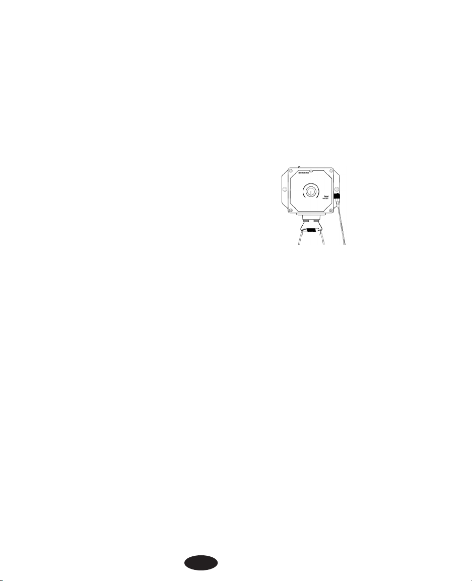
Leuchtet das rote Anzeigelicht am Sendegerät ununterbrochen auf, aber das Funkhalsband reagiert nicht, so
liegt ein Fehler am Funkhalsband vor. Die Prüfung nach Aufladen oder Wechseln der Batterie wiederholen.
Leuchtet das rote Anzeigelicht am Sendegerät ununterbrochen auf und das Funkhalsband reagiert beim
Annähern an den Prüfdraht, so liegt ein Fehler im Abgrenzkabel vor.
C. Drahtbruch ausfindig machen
Zum Ermitteln von Drahtbrüchen in der Kabelschleife kann eine HF– Drosselspule als Messgerät Verwendung
finden. Diese ist durch Radio Shack ® (Bestellnummer 273–102C) erhältlich. Sobald dieses Gerät zur Verfügung
steht, wie folgt vorgehen.
1. Das Steckernetzgerät aus der Netzsteckdose nehmen um die Stromversorgung abzuschalten.
2. Die Leitungsdrähte vom Sendegerät abklemmen.
3. Die Zuleitungen der HF– Drosselspule hufeisenförmig biegen.
4. Die Drahtenden (abisoliert) vorsichtig um die Zuleitungen der
HF– Drosselspule wickeln (an jeder Seite eines).
5. Die Zuleitungen der HF– Drosselspule in die
Anschlussklemmen am Sendegerät einführen.
6. Das Steckernetzgerät an der Netzsteckdose anschließen.
7. Einen Batterieradioempfänger auf etwa 600 kHz im
Mittelwellenband einstellen.
8. Den Knopf „Signalreichweite" (Field Width) genügend weit aufdrehen um ein Signal über das
Radio zu empfangen, wenn das Radio über dem Abgrenzkabel gehalten wird.
9. Über dem verdrillten Leitungsdraht sollte kein Signal zu empfangen sein. Sobald der Punkt ent-
lang der Grenze erreicht ist, wo nur ein einziges Kabel liegt, sollte über das Radio ein pulsierender Störpegel hörbar sein.
10. Das Radio etwa in Brusthöhe halten über dem Kabel hin– und herschwenken und dabei am
Rande der Eingrenzung entlang laufen.
11. Im Fall das der Ton verstummt, die Lautstärke oder Tonhöhe wechselt, den Punkt mit einem
Fähnchen oder Holzstab markieren. Bei Verstummen ist ein völliger Drahtbruch anzunehmen. Bei
Lautstärke– oder Tonhöhewechsel nach einem Einschnitt in der Isolierung suchen.
12. Am Rande der Eingrenzung weiter fortschreiten und jeden Signalwechsel wie zuvor markieren.
13. Die markierten Stellen nach Beendigung des Rundgangs wieder aufsuchen. Das Kabel etwa
einen Meter lang in beiden Richtungen untersuchen.
14. Beschädigte Kabellängen nötigenfalls mit Leitungsdraht von gleicher Stärke auswechseln und
mit wasserdichten Kabelverbindern zusammenfügen.
Weitere Informationen finden Sie auf unserer Webseite unter www.innotek.net.
58
Page 59

BESCHRÄNKTE INTERNATIONALE GARANTIE
INNOTEK®, Inc. garantiert dem ursprünglichen Einzelhandelskäufer, dass Produkte der Marke INNOTEK bei normalem Gebrauch für einen Zeitraum von zwei Jahren vom Kaufdatum frei von Material- und Verarbeitungsschäden
sind. Diese beschränkte Garantie deckt jedoch nicht: versehentliche Schäden,die durch Kauen des Hundes entstehen, Blitzeinschlag, wo keine INNOTEK Blitzschutzkomponenten in Gebrauch sind (unterirdisches Tierzaunsystem);
oder Nachlässigkeit, Änderungen und Missbrauch.
INNOTEK bietet während der Garantiezeit mehrere Austauschmöglichkeiten für Produkte an. Sollten Sie Service
benötigen, rufen Sie Ihr autorisiertes Innotek Service Center an, um den Serviceplan zu besprechen, der Ihrem
Bedarf am besten entspricht. Die Kosten hängen von der Bearbeitungszeit und der gewünschten Versandart ab.
Das Produkt bitte nicht zu Ihrem Händler zurückbringen.
Anschließend an die zwei Jahre vom ursprünglichen Kaufdatum werden wir Ihr Produkt zu einem festen Preis, je
nach Bestandteil, reparieren, ersetzen oder nachrüsten.
INNOTEK, Inc. übernimmt keine Haftung oder Verantwortung für Neben- oder Folgeschäden, die durch den
Gebrauch oder einen Defekt, ein Versagen oder eine Fehlfunktion des Produktes entstehen, ganz gleich ob der
Anspruch sich auf Garantie, Vertrag, Nachlässigkeit oder sonstiges stützt.
INNOTEK Produkte sind kein Ersatz für herkömmliches Gehorsamstraining. INNOTEK garantiert nicht die
Wirksamkeit seiner Produkte auf Grund der Unterschiedlichkeit in der Persönlichkeit und im Temperament
der Hunde und wegen Einflüssen, über die INNOTEK keine Kontrolle hat.
Falls Service erforderlich ist, wenden Sie sich bitte wegen einer Rücksendegenehmigungs– (RMA) Nummer
und Rücksendeanweisungen an das nächste, nachstehend aufgeführte Service Center. Wird die
Rücksendeanforderung genehmigt, schicken Sie bitte das schadhafte Teil oder das komplette System versichert an die angegebene Adresse.Versandkosten sind nicht gedeckt.
INNOTEK®ist ein Warenzeichen von Innotek, Inc.
Die Namen aller weiteren Waren oder Dienstleitungen sind das Eigentum der jeweiligen Firmen.
© 2005, INNOTEK, Inc. All rights reserved.
1000 Fuller Drive, Garrett, IN, USA 46738
www.innotek.net
Page 60

Sistema di contenimento
Guida di funzionamento
Questo collare canino elettronico Innotek®è tra i prodotti di addestramento più sicuri, umani ed efficaci in circolazione. Usato
idoneamente, lo stimolo elettronico del collare serve da distrazione che il cane troverà indesiderabile. Obbedendo, il cane
apprende rapidamente a smorzare lo stimolo, acquistando pertanto confidenza nella risposta ai vostri comandi. Come molti
prodotti di addestramento della INNOTEK, questo collare è dotato di livelli di stimolazione regolabili. Questa caratteristica consente di usare il livello che meglio corrisponde al temperamento
del proprio cane.
ATTENZIONE
Dedicare alcuni minuti alla lettura del manuale di istruzioni prima del primo uso. Questo manuale di istruzioni
contiene importanti informazioni di programmazione e preimpostazione per aiutare la riuscita esecuzione dell’addestramento. Per risultati migliori, seguire queste direttive importanti:
• Il collare canino elettronico è previsto solo per l’uso su cani.
• La maggioranza dei proprietari di cani è sorpresa su quanto può essere realizzato usando una stimolazione a basso livello; pertanto, va usata la stimolazione più bassa necessaria per ottenere il
comportamento desiderato.
• La batteria scarica potrebbe causare un funzionamento intermittente. NON USARE se si sospetta
che la batteria sia scarica.
• Consentire al cane di abituarsi al collare prima di iniziare l’addestramento. Occorre che il cane
accetti il collare come parte di routine senza associare il collare alla correzione.
• NON lasciare il collare sul cane per più di 12 ore al giorno.
• NON eseguire procedure di preimpostazione quando il collare si trova sul cane.
• Un collare elettronico dovrebbe essere usato solo sotto la stretta supervisione del proprietario del
cane.
• TENERE LONTANO DALLA PORTATA DEI BAMBINI.
• Leggere tutte le istruzioni prima di usare questo prodotto. In caso di informazioni, contattare il concessionario o il servizio assistenza Innotek più vicini.
IMPORTANTE
Occorre tener presente che i singoli cani hanno temperamenti unici, non c’è modo di sapere come reagirà il
cane al suo primo contatto con questo prodotto. Per la sicurezza del cane, l’addestramento iniziale deve
avvenire utilizzando un guinzaglio lungo per poter tenere la situazione sotto controllo. Inoltre va anche tenuto
presente che un animale aggressivo potrebbe ribellarsi a chi lo tiene all’atto della ricezione dello stimolo.
Pertanto, se si avverte che il proprio cane ha un comportamento aggressivo e/o ha precedenti di comportamento aggressivo, occorre consultare un esperto autorizzato di comportamenti animali prima di usare questo
prodotto. Fare riferimento a Addestramento del cane, Sezione 3 a pagina 69.
60
Ne Onzichtbare omheining 15
Fr Guide d’emploi 30
De Bedienungsanleitung 45
It Guida di funzionamento 60
Es Guia de Funcionamiento 75
Page 61

COME FUNZIONA
Il filo delimitativo viene collegato al trasmittente murale alimentato da un adattatore a CA. Quando viene attivato il sistema di contenimento, viene trasmesso un segnale radio attraverso il filo. Se il cane che indossa il collare ricevitore si avvicina al filo, il segnale invia al collare ricevitore l’impulso di una breve ed innocua correzione.
Naturalmente il cane cerca di evitare il filo e quindi impara rapidamente a restare nei limiti prestabiliti.
SEZIONE 1.
ISTRUZIONI PER LA PREIMPOSTAZIONE DEL SISTEMA DI CONTENIMENTO
Questo manuale di utente tratta le istruzioni sia per il collare ricevitore funzionante a batteria che per i sistemi
di contenimento del collare ricevitore ricaricabile. Nell’intero manuale vi sono annotazioni relative a ciascuno di
questi tipi di sistema.
PUNTO 1.
PREPARARE LA PIANTA DELL’AREA DI CONTENIMENTO
A. Diagramma schematico e di progettazione
Preparare un diagramma dell’area in cui si desidera contenere il proprio cane. Il diagramma aiuterà
ad evitare ostacoli imprevisti. Includere l’ubicazione della casa, vialetto d’ingresso, laghetto, giardino, piscina, ecc. Se il vicino dispone di un sistema di contenimento installato, contrassegnare sul
diagramma l’ubicazione del filo interrato.
B. Contattare la società di utenza
Contattare le società di utenza per contrassegnare qualsiasi linea di utenza interrata. Assicurarsi di
includere le linee interrate nel disegno in quanto queste linee di utenza condizioneranno la collocazione del filo.
C. Stabilire l’ubicazione del trasmettitore murale
Il trasmettitore può essere montato in un muro vicino qualsiasi presa casalinga standard di 220 volt
con le viti in dotazione. Sopporterà temperature sottozero ma non è impermeabile. Pertanto, è
meglio ubicare il trasmettitore in un’area interna.
NOTA PER I SISTEMI RICARICABILI: il trasmettitore murale deve essere montato in un ambiente
dove la temperatura ambiente si trovi tra 0 e 45 gradi centigradi.
D. Stabilire la via d’uscita del filo delimitativo dal trasmettitore all’area di contenimento ester-
na
Dal momento che il trasmettitore deve essere montato in un’area interna per proteggerlo dalle
intemperie, tenere in debita considerazione il punto in cui il filo esce all’esterno. Le aperture
esistenti come una finestra, una porta o un foro di linea d’utenza potrebbero fornire un facile accesso verso l’esterno. Potrebbe essere necessario praticare un foro attraverso il muro esterno.
PUNTO 2.
AGGIUNGERE AL DISEGNO L’UBICAZIONE PROPOSTA DI UN FILO
Contrassegnare il diagramma con la proposta ubicazione del filo. Ciò fornirà un agevole riferimento durante l’installazione del filo.
61
Page 62

Per un corretto funzionamento del sistema, il filo deve essere ininterrotto.Il segnale viene trasmesso da un terminale del trasmettitore, attraverso il filo e di nuovo all’altro terminale.
NOTE IMPORTANTI PER LA COLLOCAZIONE DEL FILO
• NON stendere il filo entro 2 metri parallelamente a fili elettrici, telefonici, televisivi o di
altro tipo interrati nel giardino.
• NON stendere una sezione di filo entro 3 metri da un’altra sezione altrimenti il segnale
potrebbe annullarsi.
• NON stendere il filo entro 3 metri da qualsiasi filo di sistema di contenimento adiacente.
PUNTO 3.
STIMARE LA QUANTITÀ DI FILO NECESSARIO
Sia il modello funzionante a batteria che quello ricaricabile includono 152 metri di filo delimitativo. Ciò può racchiudere un’area di circa 0,2 ettari.
La quantità di filo necessario viene stabilita da vari fattori:
(a)L’area totale da contenere
(b)L’uso di un doppio circuito. Ciò richiede il doppio del filo.
(c)Le dimensioni del campo di segnale. Il campo di segnale è la dis-
tanza dal filo al luogo in cui il collare ricevitore si attiva prima. Si
preferisce un campo di filo da 3 a 4 metri.
Kit delimitativi supplementari (disponibili separatamente) consentono di
aggiungere filo per contenere un’area più vasta. Il modello funzionante a
batteria può contenere fino a 2 ettari. Il modello ricaricabile può contenere
fino a 10 ettari. Ciascun kit delimitativo include 152 metri di filo, 50 bandierine da addestramento e due giunti
di filo impermeabile.
PUNTO 4.
INSTALLAZIONE DEL TRASMETTITORE MURALE
Installare il trasmettitore murale nei pressi di una presa casalinga standard da 220 volt. Non inserire nella presa
il trasmettitore fino a quando il filo delimitativo non sia in sede.
62
Consentire l’ingresso dalla porta
posteriore con contenimento sul
retro del giardino.
Tenere il cane lontano
da una determinata area.
Esempio di diagrammi di installazione
Racchiudere l’intera proprietà e pro-
teggere una
determinata area.
Page 63

PUNTO 5.
STABILIRE L’IMPOSTAZIONE DELLE DIMENSIONI DEL
GIARDINO
Il trasmettitore murale contiene un ponticello interno che
può essere regolato per giardini grandi o piccoli. Il ponticello è preimpostato in fabbrica per giardini piccoli.
L’impostazione da giardino piccolo vale per un’area che
richiede meno di 300 metri di filo. Un’impostazione da
giardino grande vale per un’area che richiede oltre 300
metri di filo.
Qualora fosse necessario modificare l’impostazione delle
dimensioni di giardino:
1. Ruotare la manopola Ampiezza di Campo (Field Width) nella posizione "off"(spento).
2. Togliere la manopola e le quattro viti che fissano la copertura del trasmettitore.
3. Spostare il ponticello all’impostazione di giardino desiderata. Il ponticello deve trovarsi in sede per
il funzionamento del trasmettitore.
• Solo sistemi ricaricabili: Il ponticello si trova sul lato inferiore del
trasmittente. SM vale per giardini piccoli; LG vale per giardini
grandi (vedere Figura 1).
• Solo sistemi funzionanti a batteria: Il ponticello si trova
sul lato destro del trasmettitore. SMALL vale per giardini
piccoli; LARGE vale per giardini grandi. Un secondo pon-
ticello è etichettato "DUAL FREQ"(DOPPIA FREQUENZA) e
"8.192 KHz." Questo ponticello deve trovarsi sempre nella
posizione "8.192 KHz" a meno che non sia disposto diversamente
da un Centro Assistenza Innotek (vedere Figura 2).
4. Ricollocare la copertura del trasmettitore e le quattro viti.
5. Reinstallare la manopola Ampiezza di Campo (Field Width) con il
puntatore nella posizione "off"(spento).
PUNTO 6.
STENDERE IL FILO PERIMETRALE
NOTA IMPORTANTE:
NON interrare il filo fino a quando non si è collaudato il sistema e si è sicuri che
questo funzioni correttamente. NON intaccare o raschiare il filo durante l’installazione. Ciò potrebbe
causare un funzionamento scorretto.
63
Polo di carica –
(solo ricaricabile)
Spia luminosa
Ampiezza di
campo
Porta di alimentazione
Terminali di filo
Solo per illustrazione. L’aspetto del
trasmettitore potrebbe variare leggermente.
Figura 1
Sistema ricaricabile
Figura 2
Sistema funzionante a batteria
INDICATOR LIGHT
Field
Width
MED LO
SM LG
SM LG
SM LG
Page 64

1. Utilizzare il disegno come riferimento. Iniziare a stendere il filo attorno al perimetro dell’area di contenimento fino a formare un circuito continuo. Utilizzare giri graduali agli angoli con un raggio minimo di 1 metro. Ciò fornirà un campo di segnale più consistente.
2. Se si utilizza più filo di quanto ne fornisce inizialmente il
sistema di contenimento, le connessioni di filo devono
essere impermeabili per offrire una connessione sigillata
tra i fili. Utilizzare solo i giunti in dotazione o quelli di un
tipo similare. Non utilizzare nastro elettrico o dadi di filo
attorcigliati. Ciò causerà un segnale intermittente o
potrebbe disarmare il sistema.
3. Continuare attorno al perimetro fino a tornare all’inizio del
circuito.
4. Tagliare il filo.
PUNTO 7.
COLLEGARE IL FILO PERIMETRALE AL TRASMETTITORE MURALE
Il filo dal perimetro al trasmettitore murale deve essere attorcigliato per annullare il segnale. Ciò consente al
cane di attraversare l’area senza ricevere alcuna correzione. Ciò elimina inoltre la possibile interferenza di fili
elettrici, ecc.
1. Misurare la distanza dal trasmettitore murale al bordo del filo perimetrale.
2. Dal momento che l’attorcigliamento del filo riduce la lunghezza del filo stesso,
moltiplicare la distanza per 1,5.
3. Misurare e tagliare due fili della stessa lunghezza della misura che precede.
4. Tenere le due estremità del filo lato a lato e attorcigliarle assieme. I fili possono
essere attorcigliati manualmente o adoperando un trapano elettrico fino a che gli
attorcigliamenti si trovino ad una distanza da 6 a 12 cm. Più stretto è l’attorcigliamento del filo più forte è l’annullamento del segnale.
5. Inserire l’estremità di uno dei fili attorcigliati in un foro di giunto di filo. NON
spelare il filo prima di collocare il filo nei fori. Inserire uno dei fili perimetrali in
uno degli altri fori del giunto di filo. Premere la parte nera superiore del giunto
con un paio di pinze.
6. Ripetere il Punto 5 per l’altra estremità del filo attorcigliato e l’altra estremità del
filo perimetrale. Un foro del giunto non verrà usato.
7. Mettere i fili attorcigliati attraverso l’apertura esistente o il foro trapanato in
modo da poterli collegare al trasmettitore.
8. Spelare circa 1 cm di isolante dall’estremità di ciascun filo attorcigliato.
9. Inserire i fili nei terminali del trasmettitore.
10. Inserire l’adattatore di alimentazione in una presa casalinga standard a 220 volt.
11. Collegare l’adattatore di alimentazione alla porta di alimentazione del trasmettitore.
64
Trasmettitore murale
ubicato in garage
Filo perimetrale
Filo attorcigliato al trasmetti-
tore murale
diagrammi di installazione
Page 65

PUNTO 8.
VERIFICARE CHE IL TRASMETTITORE FUNZIONI CORRETTAMENTE
Per verificare che il trasmettitore funzioni correttamente, cercare la spia rossa sul trasmettitore. Una spia rossa
continua indica che il trasmettitore riceve corrente, che entrambi i fili sono collegati e che il filo forma un circuito integro e continuo. La luce del trasmettitore indica solo continuità.
Se la spia rossa non è accesa, ciò significa che uno o entrambi i fili non sono collegati correttamente; entrambi i fili sono collegati ma il filo è rotto; il trasmettitore ha problemi di funzionamento; oppure l’alimentazione è
stata spenta. Correggere il problema e riprovare.
PUNTO 9.
IMPOSTAZIONE DEL COLLARE RICEVITORE
Prima di procedere, occorre assicurarsi che il sistema funzioni correttamente con il collare ricevitore. La Parte
A riguarda solo il collare ricevitore ricaricabile; la Parte B si applica al collare ricevitore funzionante a batteria.
A. Collare ricevitore ricaricabile
Le seguenti istruzioni si applicano solo al collare ricevitore ricaricabile. Se il collare ricevitore è funzionante a
batteria, fare riferimento alla seguente Parte B.
Il collare ricevitore viene caricato tramite il trasmettitore montato a muro. Per caricare il collare ricevitore per
l’uso iniziale, occorre prima installare il trasmettitore. Il collare ricevitore ricaricabile deve essere caricato per
almeno 12 ore prima di usarlo per la prima volta. IMPORTANTE! NON INTERRARE IL FILO FINO A QUANDO
NON SI È SOTTOPOSTO A PROVA IL SISTEMA CON IL COLLARE RICEVITORE E SI È CERTI CHE QUESTO FUNZIONI CORRETTAMENTE.
NOTA IMPORTANTE:
il sistema di contenimento non funzionerà mentre il collare ricevitore è in carica. Pertanto occorre programmare a) la modifica del collare ricevitore solo quando il cane può
essere controllato o altrimenti contenuto; oppure b) l’acquisto di un ulteriore collare ricevitore e un
caricatore dalla Innotek e caricare un collare ricevitore mentre l’altro è in uso. Per ordinare un altro
collare ricevitore e caricatore, contattare un Centro Assistenza Innotek.
Per caricare il collare ricevitore:
1. Attivare il trasmettitore montato a muro e collocarvici sopra il collare ricevitore. Assicurarsi che il
perno di allineamento sollevato del trasmettitore si inserisca nella piccola tacca sul fondo del collare ricevitore.
2. Verificare che il trasmettitore lampeggi. Ciò indica che il collare ricevitore
è in carica. Se il trasmettitore non lampeggia, verificare che il trasmettitore sia "on"(acceso) e controllare tutte le connessioni.
3. La spia luminosa lampeggiante si spegnerà quando il collare ricevitore è
completamente carico. I caricatori Innotek evitano automaticamente
sovraccarichi.
4. A seconda della frequenza di correzione, la carica nel collare ricevitore di
solito dura da 2 a 3 settimane.
NOTA IMPORTANTE
: NON collocare il collare ricevitore sul cane fino a quando il sistema di conteni-
mento non sia stato sottoposto a prova e il campo di segnale regolato.
5. Procedere al seguente Punto 10 per provare che il sistema funzioni correttamente.
675
Page 66

B. Collare ricevitore funzionante a batteria
Le seguenti istruzioni si applicano solo al collare ricevitore funzionante a batteria. Se il collare ricevitore è
ricaricabile, fare riferimento alla Parte A che precede.
Installazione della batteria del collare ricevitore
1. Collocare il collare ricevitore su una superficie piatta con il coperchio della batteria rivolto in alto.
2. Utilizzando una moneta o un giravite, svitare il coperchio del vano batteria.
3. Inserire una batteria alcalina da 6 volt (in dotazione) nel vano batteria con il lato positivo (+) in alto.
4. Ricollocare il coperchio del vano batteria. Assicurandosi di tenere il coperchio a contatto con la batteria, ruotare il coperchio in senso orario fino a che sia saldamente in sede.
5. A seconda della frequenza di correzione, la batteria nel collare ricevitore dura di solito da 2 a 3 settimane.
NOTA IMPORTANTE:
NON collocare il collare ricevitore sul cane fino a quando il sistema di
contenimento non sia stato sottoposto a prova e il campo di segnale regolato.
PUNTO 10.
PROVA DEL SISTEMA DI CONTENIMENTO
NON PROVARE IL SISTEMA DI CONTENIMENTO CON IL COLLARE RICEVITORE SUL CANE. Occorre manualmente
provare il sistema di contenimento per verificare che il segnale sia trasmesso correttamente attraverso il filo.
Usare la spia luminosa di prova in dotazione.
NOTA PER I SISTEMI RICARICABILI: il sistema di contenimento non funzionerà mentre il collare ricevitore è in
carica sul trasmettitore.
Per provare il sistema:
1. Ruotare la manopola Ampiezza di Campo (Field Width) in modo che la freccia sia puntata a metà
strada tra le posizioni di "off"(spento) e "high"(alto).
2. Posizionare la spia luminosa di prova sulle sonde in modo che le punte delle
sonde facciano contatto con i fili all’interno delle due aperture (vedere il diagramma). Potrebbe occorrere una leggera pressione.
3. Tenere la scatola del ricevitore senza toccare le sonde.
4. Tenerla all’altezza del collo del cane con le sonde puntate verso l’alto.
5. Avvicinare lentamente il collare ricevitore verso il filo. Ascoltare il suono di
avvertimento e osservare l’accensione della spia luminosa di prova. La luce si affievolirà con una
stimolazione leggera e si intensificherà con una stimolazione intensa.
PUNTO 11.
REGOLAZIONE DELL’AMPIEZZA DI CAMPO DEL SEGNALE
Il campo del segnale è la distanza dal filo al luogo dove il collare ricevitore si attiva
prima. La Manopola di Ampiezza di Campo (field width) regola le dimensioni del campo
del segnale, non l’intensità di correzione. La rotazione della manopola in senso orario
aumenta l’ampiezza di campo del segnale; la rotazione in senso antiorario la
diminuisce. Ruotando la manopola completamente in senso antiorario si disattiva l’alimentazione al trasmettitore.
66
Field
Width
Page 67

Seguire le istruzioni del Punto 10 per collaudare l’ampiezza di campo del segnale. Verificare l’intero perimetro
per assicurarsi che il campo del segnale sia consistente in tutta l’area di contenimento. Il campo del segnale
deve estendersi ad un minimo di 2 metri su ciascun lato del filo (creando un campo dell’ampiezza di 4 metri).
Si preferisce un’ampiezza di campo da 3 a 4 metri. Maggiore è l’ampiezza del campo del segnale, minore è la
possibilità che il cane possa attraversare il campo.
• Se Il ponticello di impostazione del proprio giardino è impostato per un giardino piccolo e non si
può aumentare il campo del segnale, impostare il ponticello alle dimensioni di giardino grande.
Vedere il Passo 5, Stabilire l’impostazione delle dimensioni del giardino per le istruzioni. Provare di
nuovo l’ampiezza di campo del segnale.
• Se il ponticello di impostazione di dimensioni del giardino è impostato per un giardino grande e non
si può ridurre il campo del segnale, impostare il ponticello alle dimensioni di giardino piccolo.
Vedere il Passo 5, Stabilire l’impostazione delle dimensioni del giardino per le istruzioni. Provare di
nuovo l’ampiezza di campo del segnale.
La spia del trasmettitore indica solo continuità. Se si ha un giunto allentato o un filo intaccato, potrebbero accendersi la spia luminosa rossa o una spia luminosa intermittente, ma si potrebbe notare un’ampiezza di campo
ridotta o annullata. Se dovesse verificarsi questa situazione o la rottura di un filo, seguire le istruzioni nella
Sezione Risoluzione dei problemi ubicata verso la fine di questa guida.
NOTA PER I SISTEMI FUNZIONANTI A BATTERIA: assicurarsi che il secondo ponticello all’interno del trasmettitore murale sia impostato a 8.192 KHZ. Questa è l’impostazione di fabbrica e non deve essere modificata a
meno che non sia indicato diversamente da un Centro Assistenza INNOTEK.
NOTA IMPORTANTE: se la manopola Ampiezza di Campo (Field Width) viene rimossa o la posizione
della manopola viene alterata ruotandola in senso orario o antiorario, occorre sempre verificare il
campo del segnale per l’impostazione desiderata. Fare riferimento al Passo 10, Prova del sistema di
contenimento.
PUNTO 12.
INSTALLAZIONE DEL FILO DELIMITATIVO
Strumenti necessari - Vanga a bordo dritto, tranciafili / spelafilo e un giravite standard. Se si programma di
stendere il filo attraverso il cemento, occorrerà anche una pistola da calafataggio, calafataggio al silicone ed
una sega circolare con una lama da muratura.
Collocazione del filo - Per un funzionamento corretto del sistema, il filo deve formare un circuito continuo.
Interramento del filo - Il filo non deve necessariamente essere interrato ma per protezione forse è meglio inter-
rarlo di almeno 2,5 cm. Iniziare scavando da 7 a 10 cm dove il filo inizialmente entra nel terreno vicino al
trasmettitore e continuare attorno al percorso del filo. Nota: quando si deve coprire una vasta area, potrebbe
occorrere l’uso di una scavafossi per terreni. Tuttavia, raccomandiamo che il filo sia collocato a mano nel terreno. Una macchina colloca-filo commerciale potrebbe rompere il filo.
Vialetti d’ingresso / marciapiedi - Quando si attraversa un vialetto d’asfalto, praticare un taglio di 2 cm di
profondità lungo il vialetto adoperando una sega circolare e una lama da muratura. Collocare il filo nella fessura
e sigillare con sigillante per asfalto. Su vialetti e marciapiedi, se è disponibile un giunto di espansione, basterà
collocare il filo nel giunto e sigillare con materiale isolante per esterni. Quando si attraversa del ghiaietto, interrare il filo ad almeno 7 cm di profondità. Adoperare un vecchio tubo flessibile da giardino o una tubatura in PVC
di plastica per proteggere il filo. In acqua, ancorare il filo con grossi sassi.Proteggere il filo con un vecchio tubo
flessibile da giardino o una tubatura in PVC di plastica.
67
Page 68

PUNTO 13.
INSTALLAZIONE DELLE BANDIERINE DI ADDESTRAMENTO DELIMITATIVE
Dopo l’installazione del filo, ricollaudare il sistema di contenimento come descritto nel Punto 10, Prova del sistema di contenimento. Verificare che l’ampiezza di campo del segnale sia consistente seguendo le istruzioni del
Punto 11, Regolazione dell’ampiezza di campo del segnale. Nel corso della nuova prova e della verifica del sistema, installare le bandierine di addestramento delimitative. Collocare le bandierine dove si avverte prima il
suono di avvertimento avvicinandosi al filo. Le bandierine devono essere collocate all’orlo dell’ampiezza di
campo del segnale, non direttamente sul filo. Ciò aggiungerà una coda visiva al suono di avvertimento audio e
aiuterà il cane ad imparare la delimitazione.
PUNTO 14.
ADATTAMENTO DEL COLLARE AL CANE
NOTA IMPORTANTE
: non lasciare mai il collare ricevitore sul cane per più di 12 ore al giorno.
Lasciare il collare sul cane per prolungati periodi di tempo potrebbe comportare irritazione cutanea.
Verificare periodicamente il collo del cane per eventuale irritazione cutanea.
A. Sonde
• Assicurarsi che entrambe le sonde siano a contatto con la pelle del cane. Se necessario, la
rimozione o l’assottigliamento di una certa quantità di pelo migliorerà il contatto delle sonde con la
pelle.
• Adoperare sonde corte per cani dal pelo corto. Adoperare sonde lunghe per cani dal pelo lungo.
Sono disponibili sonde speciali per cani dal pelo particolarmente spesso. Contattare Innotek per gli
ordinativi.
• Serrare a mano le sonde, quindi girarle un’altra volta con la chiave da sonda. Non serrare eccessivamente.
• Usare sempre gli isolanti di gomma tra il collare e le sonde per fornire isolamento in condizioni di
umidità.
• Verificare regolarmente la saldezza delle sonde per evitare la perdita della scatola del ricevitore.
B. Cinghia del collare
• Per evitare la correzione accidentale all’interno dell’abitazione, rimuovere il collare dal collo del
cane quando questi entra in casa.
• Collocare il collare attorno al collo del cane con la scatola del ricevitore sotto il mento. Il collare
deve essere relativamente stretto per tenere le sonde a contatto di pelle senza bloccare la respirazione. Si deve essere in grado di infilare un dito sotto la cinghia sulla nuca del cane.
• Assicurarsi sempre che il collare funzioni correttamente PRIMA di metterlo sul cane.
• Togliere altri collari di metallo quando il cane indossa il collare di contenimento. I collari di metallo
potrebbero interferire con il corretto funzionamento.
• Togliere il collare e tranciare l’eccesso di cinghia, lasciando da 10 a 15 cm.
68
Page 69

SEZIONE 2.
COME FUNZIONA LA CORREZIONE
1. Suono di avvertimento pre-correzione: quando il cane raggiunge l’orlo di campo del segnale nel
giardino, udrà un tono di avvertimento che dura circa due secondi. Se il cane non torna nella parte
sicura del giardino, questi riceverà una correzione continua fino al suo ritorno nell’area sicura.
2. Prevenzione di attraversamento: il ricevitore aumenta automaticamente la correzione quando il
cane entra nel campo del segnale. Il cane non può "attraversare" campo del segnale senza ricevere una forte correzione.
3. Prevenzione sulla correzione: nell’improbabile caso in cui il cane viene "intrappolato" nel campo
del segnale, il sistema si spegne per 10 secondi prima di riprendere la correzione per altri 20 secondi. Questo schema si alternerà fino a che il cane torna nell’area sicura o il sistema viene disattivato.
SEZIONE 3.
ADDESTRAMENTO DEL CANE
Per ottenere il massimo dal sistema di contenimento durante l’addestramento, ricordare quanto segue:
• Per evitare la correzione accidentale nell’abitazione, togliere il collare dal collo del cane quando
questi entra in casa.
• Assicurarsi sempre che il collare funzioni correttamente PRIMA di metterlo al cane. Verificare che
il sistema funzioni correttamente e l’ampiezza di campo sia giusta come descritto nella Sezione 1,
Punto 11, Regolazione dell’ampiezza di campo del segnale.
• Restare positivi e giocosi durante la sessione di addestramento.
• Tenere brevi sessioni di addestramento.Non continuare mai una sessione dopo che il cane ha perso
interesse. Interrompere per riposare o per giocare.
• Ricompensare SEMPRE il cane per il buon comportamento.
I Punti seguenti evidenziano un riuscito programma di addestramento:
PUNTO 1.
ADDESTRAMENTO CON LE BANDIERINE
1. Disattivare il trasmettitore murale in modo che non siano date correzioni al cane.
2. Collocare il collare ricevitore sul cane.
3. Mettere un guinzaglio lungo al cane. Giocare con il cane nell’area sicura del giardino per 2-4 minuti. Non consentire al cane di correre liberamente o di attraversare le linee con le bandierine.
4. Camminare verso le bandierine. Afferrare e agitare una bandierina. Dire "bandierina cattiva" con
tono di disapprovazione.
5. Tornare nella parte centrale del giardino e giocare con il cane. Ricompensarlo con del cibo.
6. Ripetere questo esercizio varie volte in varie zone del giardino.
69
Page 70

PUNTO 2.
LA PRIMA CORREZIONE
1. Ci sarà bisogno di reimpostare l’ampiezza di campo del segnale prima di collocare il collare ricevitore sul cane. Seguire le istruzioni evidenziate nella Sezione 1, Punto 11, Regolazione dell’ampiezza di campo del segnale.
2. Applicare il collare ricevitore al cane nell’area sicura del giardino.
3. Mettere un guinzaglio lungo al cane. Giocare con il cane nell’area sicura del giardino.
4. Camminare verso le bandierine. Se il cane cerca di evitare le bandierine, ricompensare e riassicurare il cane.
5. Ripetere questo Punto in altre zone del giardino.
6. Non consentire più di tre correzioni in un giorno o sette in una settimana. Ciò dipende dalla tolleranza del cane allo stress. La maggior parte dei cani riceve solo alcune correzioni durante la fase di
addestramento rispondendo al tono molto rapidamente.
7. Ricompensare il cane quando questi evita le bandierine, anche se viene emessa una correzione.
8. Giocare con il cane nella zona sicura prima di terminare questa sessione di addestramento.
PUNTO 3.
PROVA AL GUINZAGLIO
1. Con il collare sul cane e il trasmettitore murale "on"(acceso), giocare con il cane (al guinzaglio) nell’area sicura. Dopo alcuni minuti di gioco, lanciare un giocattolo o del cibo attraverso la bandierina.
2. Se il cane corre attraverso le bandierine per acchiappare il giocattolo, attendere il sussulto di
responso del cane e tirarlo nell’area sicura. Premiare e ricompensare il cane.
3. Rinforzare l’addestramento agitando una bandierina. Dire "bandierina cattiva" con tono di disapprovazione. Considerare l’aumento dell’area di campo del segnale. Se si sceglie di aumentare l’area
di campo del segnale, togliere il collare al cane, aumentare il campo del segnale e rifare la prova.
Fare riferimento alla Sezione 1, Punto 11, Regolazione del campo del segnale.
4. Ripetere questo esercizio in altre zone del giardino.
5. Premiare il cane quando evita le bandierine. restare positivi e giocosi durante la sessione di addestramento.
6. Quando il cane rifiuta di correre attraverso le bandierine 20 volte consecutive, procedere al Punto
successivo.
PUNTO 4.
PROVA SENZA GUINZAGLIO
1. Seguire le istruzioni al Punto 3, Prova al guinzaglio, lasciando cadere a terra il guinzaglio in modo
da tenerlo disponibile se occorrerà riprendere il cane.
2. Se durante questa fase il cane oltrepassa il campo del segnale, togliere rapidamente il collare.
Portare il cane nell’area sicura. Rimettere il collare al cane. Rinforzare l’addestramento "bandierina cattiva". Premiare e ricompensare il cane.
3. Ripetere quest’addestramento senza guinzaglio fino a che si ha fiducia che il cane ignorerà le tentazioni all’esterno dell’area di contenimento.
70
Page 71

SEZIONE 4.
SUGGERIMENTI DI MANUTENZIONE DEL SISTEMA
Il sistema richiede poca manutenzione. Il collare ricevitore funzionante a batteria è resistente all’acqua e non
deve essere immerso in alcun liquido. Ciò causerà danni non coperti dalla garanzia del fabbricante. Il collare
ricaricabile è impermeabile e continuerà a funzionare dopo essere stato immerso in acqua. Per togliere lo
sporco, basta pulire con acqua e sapone. Non mettere mai il collare nella lavastoviglie.
Il trasmettitore murale non è impermeabile e deve essere protetto dalle intemperie. Un fulmine a distanza ravvicinata potrebbe danneggiare l’unità. Durante il maltempo staccare il trasmettitore e staccare i fili.
Non cercare di smantellare o riparare alcun componente del sistema; ciò annullerà la garanzia del fabbricante.
Questi componenti contengono un circuito computerizzato che deve essere riparato solo da personale esperto
autorizzato.
Collaudare il sistema una volta alla settimana per assicurarsi che il collare ricevitore funzioni correttamente.
Inoltre, il collaudo del sistema verificherà che l’impostazione dell’ampiezza di campo sia corretta. Per il collaudo, collegare la spia luminosa in dotazione alle sonde del collare ricevitore. Tenendo il ricevitore per la cassa,
NON per le sonde, camminare nel campo del segnale. Verificare se si sente il suono di avvertimento e se si
accende la spia luminosa.
NOTA PER I SISTEMI RICARICABILI
Ogni sei mesi, il collare ricevitore deve essere interamente scaricato e quindi ricaricato. Per scaricare il ricevitore, attivare il sistema e collocare il collare ricevitore con la spia luminosa di prova collegata nel campo del
segnale. Quando il ricevitore non emette più il suono e la spia luminosa di prova non si illumina, vuol dire che
è completamente scarico. Usare sempre la spia luminosa di prova quando si scarica il collare ricevitore, altrimenti quest’ultimo si potrebbe danneggiare permanentemente.
SEZIONE 5.
DIRETTIVE DI RISOLUZIONE DEI PROBLEMI
A. Il cane non risponde alla correzione:
• Regolare la misura del collare.
• Tagliare il pelo del cane o adoperare sonde più lunghe per ottenere un contatto migliore con la
pelle.
• Cambiare e/o ricaricare la batteria nel collare ricevitore.
• Assicurarsi che il ponticello del trasmettitore murale sia impostato a 8.192 kHz. (Solo nel sistema
ricevitore funzionante a batteria).
Per ulteriori informazioni, visitare il sito web www.innotek.net.
NOTA PER I SOLI SISTEMI RICARICABILI
Se il cane non risponde alla correzione, il sistema ricaricabile ha l’opzione di impostare il livello di correzione
sul trasmettitore murale a low (basso) medium (medio) o high (alto). L’impostazione di fabbrica è Medio. Per
modificare il livello:
71
Page 72

1. Ruotare la manopola Ampiezza di Campo (Field Width) nella posizione "off"(spento).
Togliere la manopola, le viti del coperchio e il coperchio frontale.
2. Il ponticello nell’angolo in alto a destra del trasmettitore può essere spostato a
destra per l’impostazione Low (basso) o rimosso completamente per l’impostazione
High (alto).
3. Ricollocare il coperchio del trasmettitore e le quattro viti del coperchio.
4. Installare la manopola con il puntatore nella posizione
"off"(spento).
5. Riprovare l’ampiezza di campo del segnale come descritto nel
Passo 10.
NOTA: se il trasmettitore è impostato su High (alto), non vi sarà
alcun suono di pre-correzione.
B. Procedura di collaudo del sistema:
Qualora si verificasse un cattivo funzionamento, occorrerà eseguire una Prova di circuito per stabilire quale
componente - collare, trasmettitore murale o filo da giardino – non funziona. Per eseguire la procedura di Prova
di Circuito:
1. Eseguire una prova di circuito usando un pezzo di filo di almeno 4 metri di lunghezza.
2. Togliere il filo esistente dal trasmettitore murale.
3. Inserire le due estremità del filo di prova di circuito nel trasmettitore murale.
4. Ruotare la manopola Ampiezza di Campo (Field Width) in
posizione ore 9 o ad un’impostazione bassa.
5. Collocare la spia luminosa di prova sul collare ricevitore. Con il
collare in mano, spostarsi fuori del campo e avvicinare il circuito di prova. Ricordarsi la distanza tra il collare e il filo quando viene attivato il collare.
6. Ruotare la manopola Ampiezza di Campo (Field Width) in
posizione ore 12 o ad un’impostazione media.
7. Allontanarsi dal filo e avvicinarsi di nuovo ad esso. Stabilire la
distanza tra il collare e il filo quando viene attivato il collare. La distanza deve essere maggiore sull’impostazione di raggio medio.
8. Se con il sistema viene usato più di un collare ricevitore, ripetere la prova che precede con ciascun
collare.
Risultati delle procedure di prova del sistema:
Se non si accende la spia luminosa rossa sul trasmettitore murale con il filo del circuito di prova in sede, il
trasmettitore murale non funziona correttamente.
Se la spia luminosa rossa è fissa sul trasmettitore murale ma il collare non si attiva sul filo del circuito di prova,
il collare ricevitore non funziona. Cambiare o ricaricare la batteria nel collare ricevitore e ripetere la prova.
Se la spia luminosa rossa è fissa sul trasmettitore murale e il collare si attiva avvicinando il filo del circuito di
prova, il problema è nel filo da giardino.
72
INDICATOR LIGHT
SMART DOG
Field
Width
Page 73

C. Localizzazione delle rotture di filo
Per localizzare le rotture di filo nell’installazione del circuito, adoperare un dispositivo di localizzazione di rottura
di filo chiamato RF- Choke, disponibile presso RadioShack
®
(Catalogo N.ro 273-102C). Una volta in possesso di
questo dispositivo, procedere nel modo seguente:
1. Staccare l’alimentazione staccando l’adattatore dalla presa.
2. Staccare i fili dal trasmettitore murale.
3. Piegare i poli dell’RF-Choke a forma di ferro di cavallo.
4. Avvolgere delicatamente le estremità del filo (scoperto) attorno
ai poli dell’RF-Choke (uno per lato).
5. Inserire i poli dell’RF-Choke nei terminali sul trasmettitore.
6. Inserire l’adattatore nella presa.
7. Impostare una radio AM portatile ad una frequenza di circa 600 kHz.
8. Impostare la manopola Ampiezza di Campo (Field Width) abbastanza alta in modo da ottenere un
segnale sulla radio portatile quando si tiene la radio sul filo di contenimento.
9. Il segnale deve essere assente sulle porzioni di filo attorcigliato in quanto l’attorcigliamento
annulla il segnale. Quando si raggiunge un’area di confine con filo individuale, si dovrebbero
sentire impulsi statici alla radio.
10. Tenere in alto la cassa della radio e farla oscillare sul filo mentre si cammina lungo la delimi-
tazione.
11. Se il suono si arresta, si indebolisce o cambia picco, contrassegnare la zona con una bandieri-
na o un paletto. Nessun suono indica una rottura completa nel filo. Se il segnale svanisce o cambia picco, cercare una tacca nell’isolamento.
12. Continuare attorno alla delimitazione rimanente e contrassegnare ciascuna modifica di segnale
con una bandierina o un paletto.
13. Dopo il completamento dell’intera delimitazione, tornare alle zone contrassegnate. Esaminare il
filo per 1 metro circa in ciascuna direzione.
14. Sostituire il filo danneggiato adoperando lo stesso filo indicatore utilizzato nell’installazione orig-
inale e utilizzare giunti di filo impermeabili per eseguire la connessione.
Per ulteriori informazioni, visitare il nostro sito web www.innotek.net.
GARANZIA LIMITATA INTERNAZIONALE
INNOTEK®, Inc., garantisce all’acquirente al dettaglio originale, che i prodotti di marca INNOTEK saranno esenti da difetti di materiale e manodopera, con l’uso normale, per un periodo di due anni dalla data dell’acquisto al
dettaglio originale. Questa Garanzia Limitata esclude: danni accidentali causati dai morsi del cane; danni da fulmini laddove non sia in uso un componente di protezione dai fulmini della INNOTEK (sistemi di recinzione per
animali domestici interrati); o negligenza, alterazione e cattivo uso.
INNOTEK offre numerose opzioni di scambio di prodotto durante il periodo di garanzia. Se occorre assistenza,
chiamare il Centro Assistenza Innotek autorizzato per discutere il programma di servizio che meglio si adatta
alle proprie esigenze. I costi dipendono dai tempi di lavorazione e dalle opzioni di spedizione desiderati. Non
restituire questo prodotto al dettagliante.
73
Page 74

Dopo due anni dalla data di acquisto al dettaglio originale, ripareremo, sostituiremo o potenzieremo il prodotto
ad un tasso fisso basato sul componente.
INNOTEK, Inc., non sarà responsabile per qualsiasi danno incidentale o consequenziale risultante dall’uso del
prodotto o causato da qualsiasi difetto, guasto o malfunzione del prodotto, se il reclamo si basa su garanzia,
contratto, negligenza o altro.
I prodotti INNOTEK non sono sostituti dell’addestramento di obbedienza tradizionale. INNOTEK non garantisce
l’efficacia dei suoi prodotti a causa di variazioni nella personalità, del temperamento e delle influenze canine al
di fuori del controllo di INNOTEK.
Se occorre assistenza, contattare il Centro Assistenza più vicino come consigliato qui sotto per ottenere un
numero di Autorizzazione Restituzione Merce (RMA) e le istruzioni di restituzione. Se viene approvata la richiesta di restituzione, inviare il pezzo difettoso o il sistema completo tramite corriere assicurato all’indirizzo specificato. I costi di spedizione non sono inclusi.
INNOTEK è un marchio di fabbrica della INNOTEK, Inc.
Tutti gli altri nomi di prodotto o servizio sono di proprietà dei loro rispettivi proprietari.
© 2005, INNOTEK, Inc.Tutti i diritti sono riservati.
1000 Fuller Drive, Garrett, IN,USA 46738
www.innotek.net
Page 75

Sistema de Contención
Guía de funcionamiento
Este collar electrónico para perros INNOTEK®está entre los
productos para entrenamiento más humanos, seguros y efectivos que usted pueda comprar.Cuando se utilice el collar correctamente, la estímuloelectrónica del mismo actuará como
una distracción que su perro encontrará poco agradable. Al
obedecer, su perro aprende rápidamente a detener el estímulo, logrando de esta manera cobrar confianza al responder a
sus órdenes. Como la mayoría de los productos para entrenamiento de Innotek, este collar tiene niveles de estímulo graduables. Esta característica le permite utilizar el nivel que mejor se adapte al temperamento de su
perro.
PRECAUCIÓN
Por favor tómese unos pocos minutos para leer el manual de instrucciones antes de usarlo por primera vez.
Este manual de instrucciónes contiene datos importantes sobre la programación y ajuste del collar para ayudarle a que su entrenamiento sea lo más eficaz posible. Para obtener mejores resultados siga estas normas
fundamentales:
• Este collar electrónico para perros tiene como finalidad la de ser utilizado solamente en perros.
• La mayoría de los propietarios de perros se sorprenden del buen resultado que obtienen al utilizar
solamente niveles de estímulo bajos, por lo tanto, utilice los niveles de estímulo más bajos que le
ayuden a obtener el comportamiento deseado.
• Una pila con poca carga puede causar un funcionamiento intermitente. Si usted sospecha que la
pila puede estar baja NO DEBE UTILIZAR EL COLLAR.
• Antes de comenzar con el entrenamiento, permita que su perro se acostumbre al collar. Usted
quiere que su perro acepte el collar como parte de una rutina y no que asocie el collar con corrección del comportamiento.
• NO DEJE colocado el collar en su perro durante más de 12 horas diarias.
• NUNCA ejecute los procedimientos de selección de las posiciones de ajuste del collar cuando su
perro lo tenga puesto.
• El collar electrónico se deberá utilizar solamente cuando el dueño del perro supervise atentamente
su uso.
• MANTENER ALEJADO DEL ALCANCE DE LOS NIÑOS.
• Antes de utilizar este producto, lea todas las instrucciones. Si usted tiene preguntas o hay algo que
le preocupa, póngase en contacto con su agente o con el centro de servicio Innotek más cercano.
IMPORTANTE
Usted debe tener en cuenta que, dado que cada perro es un individuo único y tiene un temperamento que le
es propio, no hay manera de saber cómo reaccionará su perro cuando se le ponga en contacto con este producto. Para la seguridad de su perro, el entrenamiento inicial se deberá llevar a cabo usando una correa larga
para que usted mantenga el control de la situación. También tenga en cuenta que si el animal es agresivo, al
recibir el estímulo se puede volver en contra del entrenador.Por lo tanto, si usted considera que su perro tiene
un comportamiento agresivo y/o tiene un historial de comportamiento agresivo, antes de utilizar este producto
deberá consultar con un profesional acreditado en comportamiento animal. Por favor remítase a la Sección 3
en la página 85 sobre Entrenamiento de su perro.
75
Ne Onzichtbare omheining 15
Fr Guide d’emploi 30
De Bedienungsanleitung 45
It Guida di funzionamento 60
Es Guia de Funcionamiento 75
Page 76

FUNCIONAMIENTO
El cable para delimitación está conectado al transmisor en la pared, que a su vez está alimentado por medio
del adaptador de CA. Cuando se conecta el sistema de contención, a través del cable se transmite una señal
de radio. Si un perro que tiene colocado el collar se acerca al cable, la señal hace que el receptor del collar
emita un estímulo breve e inofensivo de corrección del comportamiento. El perro naturalmente trata de evitar
el cable y de esta manera aprende rápidamente a permanecer dentro de los límites establecidos.
SECCIÓN 1.
INSTRUCCIONES PARA LA SELECCIÓN DE LAS POSICIONES DE
AJUSTE DE SU SISTEMA DE CONTENCIÓN
Este manual del propietario contiene las instrucciones para ambos sistemas de contención, tanto para el sistema con receptor de collar que funciona con pila reemplazable, como la del sistema con receptor de collar
recargable. A lo largo de este manual usted encontrará las indicaciones correspondientes a cada uno de estos
tipos de sistemas.
PASO 1.
PREPARACIÓN DE UN DIAGRAMA DE SU ÁREA DE CONTENCIÓN
A. Diseñe y dibuje el diagrama
Prepare un diagrama del área en la que desea contener a su perro. Un diagrama le ayudará a evitar los obstáculos imprevistos. Incluya la ubicación de la casa, la entrada para coches, el jardín, la piscina, etc. Si su vecino
tiene instalado un sistema de contención, marque en su diagrama la ubicación del cable enterrado.
B. Póngase en contacto con la compañía de servicios públicos
Póngase en contacto con las compañías de servicios públicos para marcar cualquier tubería enterrada de servicios públicos. Asegúrese de incluir en su plano las tuberías enterradas dado que estas tuberías de servicios
públicos afectarán la ubicación de su cable.
C. Determine la ubicación del emplazamiento del transmisor en la pared
El transmisor se puede montar en una pared cerca de cualquier enchufe estándar de 220 voltios con los tornillos que se incluyen. El mismo aguantará temperaturas de congelación, pero no es impermeable. Por lo tanto,
es mejor colocar el transmisor en un área cerrada.
NOTA PARA SISTEMAS RECARGABLES: El transmisor en la pared se deberá colocar en un lugar en el que la
temperatura ambiente esté entre los 0º C y los 45º C.
D. Determine la ruta de salida de su cable para delimitación, desde el transmisor hacia el área exterior
de contención
Dado que usted debe montar el transmisor en un área cerrada para protegerlo del clima, considere con mucho
cuidado por dónde hará salir el cable hacia el exterior.Aberturas existentes tales como una ventana, una puerta o un orificio para canalizaciones de servicios públicos pueden proveerle un acceso fácil hacia el exterior.
Puede ser necesario que tenga que hacer un agujero a través de una pared exterior.
76
Page 77

PASO 2.
DIBUJO EN EL DIAGRAMA DE LA UBICACIÓN PROPUESTA PARA EL CABLE
Marque en su diagrama la ubicación propuesta para el cable. De esta manera tendrá una referencia fácil a
medida que instale el cable.
Para que el sistema funcione correctamente, el cable deberá seguir una curva continua. La señal se transmitirá desde una de las terminales del transmisor, a través del cable y de vuelta a la otra terminal.
NOTAS IMPORTANTES PARA LA UBICACIÓN DEL CABLE:
• NO haga pasar el cable dentro de los 2 metros paralelos a un cable de electricidad, de
teléfono, de televisión u otro cable enterrado en el terreno.
• NO haga pasar una sección de cable dentro de los 3 metros de otra sección o de lo
contrario la señal se puede anular.
• NO haga pasar su cable dentro de los 3 metros de cualquier cable de un sistema de
contención adyacente.
PASO 3.
ESTIMACIÓN DE LA CANTIDAD DE CABLE NECESARIO
Tanto el modelo que funciona a pila como el recargable incluyen 152 metros de cable para delimitación. Con
esta cantidad se puede delimitar un área de aproximadamente 0,2 hectáreas.
La cantidad de cable necesario está determinada por diversos factores:
(a)El área total a delimitar.
(b)El hecho de que se use una curva doble. Esto requerirá el doble de
cable.
(c)El tamaño del campo de la señal. El campo de la señal es la distan-
cia desde el cable hasta el lugar en que el receptor del collar se activa por primera vez. De preferencia este campo será de 3 a 4 metros
de ancho.
77
para permitir entrada por
la puerta trasera con contención en
el terreno trasero.
para mantener al perro alejado
de un área específica.
Ejemplo de diagramas de instalación
para cercar toda la propiedad y prote-
ger un área
determinada.
Page 78

Los juegos adicionales para delimitación (que se ofrecen por separado) le permiten añadir cable para contener
un área más grande. Con el modelo que funciona a pila se puede delimitar un área de hasta 2 hectáreas. Con
el modelo recargable se puede delimitar un área de hasta 10 hectáreas. Cada juego para delimitación incluye
152 metros de cable, 50 banderines para entrenamiento y dos empalmes impermeables para el cable.
PASO 4.
INSTALACIÓN DEL TRANSMISOR EN LA PARED
Instale el transmisor en la pared dentro de la vivienda, cerca
de un enchufe estándar de 220 voltios. No enchufe el transmisor en el enchufe hasta que el cable delimitador esté en su
lugar.
PASO 5.
DETERMINACIÓN DE LA POSICIÓN DE AJUSTE
PARA EL TAMAÑO DE TERRENO
El transmisor en la pared contiene una conexión interna en
puente que se puede colocar en una posición para terrenos
pequeños o grandes. La conexión en puente sale de fábrica en
la posición para terrenos pequeños. La posición para terrenos
pequeños es para un área que requiere menos de 300 metros de cable. La posición para terrenos grandes es para un
área que requiere más de 300 metros de cable.
De ser necesario cambiar la posición para el tamaño de terreno:
1. Gire la perilla de la Amplitud de campo (Field Width) a la posición "off" (apagado).
2. Retire la perilla y los cuatro tornillos que aseguran la cubierta del transmisor.
3. Mueva la conexión en puente a la posición de
terreno deseada. Para que el transmisor funcione, la conexión en puente deberá estar en su
lugar.
• Sólo para sistemas recargables: La conexión en puente
está ubicada abajo en el lado izquierdo del transmisor.SM
es para terrenos pequeños; LG es para terrenos grandes
(ver Figura 1).
• Sólo para sistemas con funcionamiento a pila: La conexión en
puente está ubicada en el lado derecho del transmisor. SMALL es para terrenos
pequeños; LARGE es para terrenos grandes. Una segunda
conexión en puente está rotulada "DUAL FREQ" (DOBLE FRECUENCIA) y "8.192 kHz." Esta conexión en puente deberá
estar siempre en la posición "8.192 kHz" a menos que un
Centro de Servicio Innotek indique lo contrario (ver Figura 2).
4. Vuelva a colocar la cubierta del transmisor y los cuatro tornillos.
5. Vuelva a instalar la perilla de Amplitud de Campo (Field
Width) con la flecha apuntando hacia la posición de "off"
(apagado).
Figura 1
Sistema recargable
Figura 2
Sistema con funcionamiento a pila
78
Clavija de carga –
(modelo recargable
solamente)
Luz indicadora
Amplitud
de campo
Conexión de
energía
Terminales del cable
Para ilustración solamente. La apariencia de
su transmisor puede variar levemente.
INDICATOR LIGHT
Width
Field
MED LO
SM LG
SM LG
SM LG
Page 79

PASO 6.
EJECUCIÓN DEL TRAZADO DEL PERÍMETRO DEL CABLE
NOTA IMPORTANTE: NO entierre el cable hasta haber probado el sistema y estar seguro de que funcione correctamente. NO haga muescas ni raspe el cable durante la instalación. Esto ocasionará un
mal funcionamiento.
1. Utilice su diagrama como referencia. Comience tendiendo el cable alrededor del perímetro de su
área de contención hasta completar una curva continua. En las esquinas utilice vueltas graduales
con un radio mínimo de 1 metro. De esta manera la señal de campo será más consistente.
2. Si usted está utilizando más cable del que se suministró inicialmente con su sistema de contención, las conexiones del cable deberán ser impermeables para lograr una conexión hermética entre los
cables. Por esta razón, utilice solamente los empalmes
provistos u otros del mismo tipo. No utilice cinta aislante
para electricidad ni tuercas para cables trenzados. Esto
ocasionará una señal intermitente o desarmará el sistema.
3. Continúe alrededor de su perímetro hasta que encuentre nuevamente el comienzo de la curva.
4. Corte el cable.
PASO 7.
CONEXIÓN DEL CABLE DE DELIMITACIÓN DEL PERÍMETRO, AL TRANSMISOR EN LA PARED
Para anular la señal, se deberá trenzar el cable que va desde el perímetro al transmisor en la pared. Esto permite que el perro cruce el área sin recibir la señal de corrección del comportamiento. También elimina la posibilidad de interferencia con cables eléctricos, etc.
1. Mida la distancia desde el transmisor en la pared hasta el borde del cable del perímetro.
2. Dado que al trenzar el cable se disminuye la longitud del mismo, multiplique la distancia por 1,5.
3. De acuerdo con la medida tomada arriba, mida y corte dos cables de igual longitud.
4. Sostenga los dos extremos del cable lado a lado y tréncelos juntos. Los
cables se pueden trenzar manualmente o utilizando un taladro motorizado
hasta que el trenzado esté apretado de 6 a 12 cm. Cuanto más apretado
se trence el cable mejor se anulará la señal.
5. Introduzca el extremo de uno de los cables trenzados en uno de los agu-
jeros del empalme de cables. NO desforre el cable antes de introducirlo en
los agujeros. Introduzca uno de los cables del perímetro dentro del otro
agujero del empalme de cables. Con una pinza, presione la parte superior
negra del empalme.
6. Repita el paso 5 para el otro extremo del cable trenzado y el otro extremo
del cable del perímetro. Uno de los agujeros del empalme no se utilizará.
7. Ponga los cables trenzados a través de las aberturas existentes o del agu-
jero taladrado de manera tal que se pueda conectar al transmisor.
8. Desforre alrededor de 1 cm del forro del extremo de cada cable trenzado.
9. Introduzca los cables dentro de las terminales del transmisor.
10. Enchufe el adaptador de corriente en un enchufe estándar de 220 voltios
de la vivienda.
11. Conecte el adaptador de corriente en el orificio para la conexión eléctrica
del transmisor.
79
Transmisor en la pared ubicado en el garaje
CABLE para
delimitación del
perímetro
CABLE trenzado
al transmisor en
la pared
Installation Diagram
Page 80

PASO 8.
VERIFICACIÓN DE QUE EL TRANSMISOR ESTÉ FUNCIONANDO CORRECTAMENTE
Para verificar que el transmisor está funcionando correctamente, fíjese en la luz roja del transmisor. Una luz roja
continua significa que el transmisor está recibiendo energía, que los dos cables están conectados y que el cable
recorre una curva continua sin quiebres. La luz del transmisor sólo le indica la continuidad del sistema.
Si la luz roja no aparece, esto le indica que uno o los dos cables no están conectados correctamente, que los
dos cables están conectados pero el cable está cortado, que el transmisor no funciona correctamente o que se
ha cortado la electricidad. Corrija el problema y pruebe nuevamente.
PASO 9.
PROGRAMACIÓN DEL RECEPTOR DEL COLLAR
Antes de proceder,usted deberá asegurarse primero que el sistema funciona correctamente con el receptor del
collar. En el punto A se indican solamente las instrucciones para el receptor de collar recargable y en el punto
B las del receptor de collar con funcionamiento a pila.
A. Receptor de collar recargable
Las siguientes instrucciones corresponden solamente al receptor de collar recargable. Si su receptor de collar
funciona a pila, por favor continúe leyendo el punto B más abajo.
El receptor del collar se carga con el transmisor en la pared. Para cargar el receptor del collar la primera vez,
usted deberá instalar primero el transmisor.
El receptor recargable del collar se deberá cargar durante por lo menos 12 horas antes de que usted lo utilice
por primera vez. ¡IMPORTANTE! NO ENTIERRE EL CABLE HASTA QUE USTED HAYA PROBADO EL SISTEMA CON
SU RECEPTOR DEL COLLAR Y ESTÉ SEGURO DE QUE FUNCIONA CORRECTAMENTE.
NOTA IMPORTANTE: Mientras el receptor del collar está cargando, el sistema de contención no funcionará. Por lo tanto, usted deberá planificar a) cargar el receptor del collar sólo mientras usted
pueda vigilar a su perro o pueda confinarlo de alguna manera, o b) comprar un cargador y receptor
de collar adicional de INNOTEK y cargar un receptor de collar mientras el otro está en uso. Para pedir
un receptor de collar y cargador adicional, póngase en contacto con un Centro de Servicio INNOTEK.
Para cargar el receptor del collar:
1. Encienda el transmisor montado en la pared y coloque el receptor del
collar arriba del mismo. Asegúrese que la clavija de alineamiento que
sobresale del transmisor encaje en la pequeña indentación en la parte
inferior del receptor del collar.
2. Controle que la luz del transmisor esté parpadeando. Esto indica que el
receptor del collar está cargando. Si la luz del transmisor no parpadea,
controle que el transmisor esté en ''on'' (encendido) y controle todas las
conexiones.
3. Cuando el receptor del collar esté completamente cargado, la luz indicadora que parpadea se apagará. Los cargadores de Innotek previenen automáticamente que se produzca una sobrecarga.
4. Dependiendo de la frecuencia de uso, la carga del receptor del collar generalmente dura de 2 a 3
semanas.
NOTA IMPORTANTE: NO coloque el receptor del collar en su perro hasta que haya probado el sistema
de contención y haya ajustado el campo de la señal.
80
Page 81

5. Para probar el sistema y comprobar que el funcionamiento es correcto, proceda al Paso 10 más
abajo.
B. Receptor de collar con funcionamiento a pila
Las siguientes instrucciones corresponden solamente al receptor de collar que funciona a pila. Si su receptor
de collar es recargable, por favor remítase al punto A de arriba.
Instalación de la pila en el receptor del collar
1. Coloque el receptor del collar sobre una superficie plana con la tapa del compartimento de la pila mirando hacia arriba.
2. Utilizando una moneda o un destornillador, destornille la tapa del compartimento de la pila.
3. Introduzca una pila alcalina de 6 voltios (se incluye) en el compartimento de la
pila con el lado positivo (+) hacia arriba.
4. Vuelva a colocar la tapa del compartimento de la pila. Cuidando de que la tapa quede en contacto
con la pila, gire la tapa en el sentido de las manecillas del reloj hasta que quede asentada firmemente.
5. Dependiendo de la frecuencia de uso, la pila en el receptor del collar dura de 2 a 3 semanas.
NOTA IMPORTANTE: NO coloque el receptor del collar en su perro hasta que haya probado el sistema
de contención y haya ajustado el campo de la señal.
PASO 10.
PRUEBA DEL SISTEMA DE CONTENCIÓN
NO PRUEBE EL SISTEMA DE CONTENCIÓN CUANDO SU PERRO TENGA COLOCADO EL RECEPTOR DEL COLLAR.
El sistema de contención se deberá probar manualmente para verificar que la señal se transmite correctamente
a través del cable. Para ello, utilice la luz de prueba que se incluye.
NOTA PARA SISTEMAS RECARGABLES: Mientras el receptor del collar esté cargando en el transmisor,el sistema de contención no funcionará.
Para probar el sistema:
1. Gire la perilla de la amplitud de campo (field width) de manera que la flecha apunte a la mitad de
la distancia entre las posiciones de "off" (apagado) y "high" (alta).
2. Ubique la luz de prueba en los electrodos de manera que las puntas de los electrodos hagan contacto con los cables dentro de las dos aberturas (ver diagrama). Puede ser que se necesite aplicar
una presión leve.
3. Sostenga la caja del receptor sin tocar los electrodos.
4. Sosténgala a la altura del cuello del perro con los electrodos apuntando
hacia arriba.
5. Camine lentamente con el receptor del collar hacia el cable. Escuche el tono
de advertencia y fíjese cuando se encienda la luz de la lámpara de prueba.
La luz será débil para una estímuloleve y brillante para una estímulointensa.
81
Page 82

PASO 11.
AJUSTE DE LA AMPLITUD DE CAMPO DE LA SEÑAL
La amplitud de campo de la señal es la distancia desde el cable hasta el lugar donde
el receptor del collar se activa por primera vez. La perilla de amplitud de campo (field
width) es la que se utiliza para ajustar el tamaño del campo de la señal y no la intensidad de la señal de corrección del comportamiento. Cuando se gire la perilla en el sentido de las manecillas del reloj se aumenta la amplitud de campo de la señal y cuando
se la gire en sentido opuesto a las manecillas del reloj se disminuye la misma. Cuando
se gire la perilla completamente en sentido opuesto a las manecillas del reloj se apagará el transmisor.
Para probar la amplitud de campo de la señal, siga las instrucciones del Paso 10.Camine alrededor de todo el
perímetro para asegurarse que el campo de la señal es consistente a través de toda su área de contención. El
campo de la señal se deberá extender como mínimo 2 metros a cada lado del cable (creando un campo con
una amplitud de 4 metros). Es preferible que la amplitud de campo sea de 3 a 4 metros. Cuanto más amplia
sea la amplitud de campo de la señal, menor será la probabilidad de que el perro pueda traspasar el campo.
• Si la conexión en puente para seleccionar el tamaño del terreno está posicionada para un terreno
pequeño y usted no puede aumentar ya más la amplitud de campo de la señal, mueva la conexión
en puente a la posición para un tamaño de terreno grande. Para las instrucciones al respecto vea
el Paso 5, Determinación de la Posición de Ajuste del Tamaño del Terreno. Luego vuelva a probar
la amplitud de campo de la señal.
• Si la conexión en puente para seleccionar el tamaño de terreno está posicionada para un terreno
grande y usted no puede disminuir ya más la amplitud de campo de la señal, mueva la conexión
en puente a la posición para un tamaño de terreno pequeño. Para las instrucciones al respecto vea
el Paso 5, Determinación de la Posición de Ajuste del Tamaño del Terreno. Luego vuelva a probar
la amplitud de campo de la señal.
La luz del transmisor,sólo indica continuidad. Si hay un empalme flojo o un cable tiene una muesca, puede ser
que usted todavía vea una luz roja u oscilante, pero usted puede notar que la amplitud de campo es reducida
o inexistente. Si ocurriera esta situación o se cortara un cable, siga las instrucciones de la Sección Detección
de Averías que está ubicada casi al final de esta guía.
NOTA PARA LOS SISTEMAS QUE FUNCIONAN A PILA: Asegúrese que la segunda la conexión en puente que
se encuentra dentro del transmisor en la pared, esté posicionada para 8.192 kHz. Esta es la posición con la que
sale de fábrica y la misma no se deberá cambiar a menos que lo indique un Centro de Servicio de Innotek.
NOTA IMPORTANTE: Si se saca la perilla de la amplitud de campo (field width) o se altera la posición de la perilla girándola en el sentido de las manecillas del reloj o en el sentido inverso de las
manecillas del reloj, usted deberá controlar siempre el campo de la señal para obtener el ajuste
deseado. Remítase al Paso 10, Prueba del Sistema de Contención.
842
Field
Width
Page 83

PASO 12.
INSTALACIÓN DEL CABLE DE DELIMITACIÓN DEL PERÍMETRO
Herramientas necesarias - Pala para cavar de canto recto, cortador /desforrador de cable, y destornillador
estándar. Si usted planea colocar el cable a través de un piso de cemento, usted también necesitará una pistola para calafatear, calafate de silicona y una sierra circular con una cuchilla para mampostería.
Colocación del cable - Para que el sistema funcione correctamente, el cable deberá recorrer una curva continua.
Enterrado del cable - No es necesario que el cable esté enterrado, pero para protección usted puede desear
enterrarlo por lo menos dos centímetros y medio bajoterreno. Comience excavando, alrededor de 7 a 10 cm de
profundidad, al principio del cable en donde éste entra en el terreno cerca del transmisor y continúe alrededor
del recorrido de la curva de cable. Nota: cuando cubra un área grande,para cortar el terreno usted puede querer usar una máquina zanjadora. Sin embargo, nosotros recomendamos que el cable sea colocado en la fosa
con la mano. Una máquina comercial de tendido de cable puede cortar el cable.
Entrada de automóviles / veredas - Cuando haya que cruzar una entrada de automóviles de asfalto, utilizando
una cierra circular y una cuchilla de albañilería, efectuar un corte de 2 cm de profundidad a través de la entrada de automóviles. Ubique el cable en la grieta y selle con sellador asfáltico. Tanto en las entradas de
automóviles como en las veredas, si hay disponible una junta de expansión, simplemente ubique el cable en la
junta y selle con material para calafatear, para exteriores. Cuando el cable cruce a través de grava entiérrelo
por lo menos a 7 cm de profundidad. Para proteger el cable,utilice una vieja manguera de jardín o un tubo plástico de PVC. En el agua, ancle el cable con piedras grandes. Proteja el cable con una vieja manguera de jardín
o un tubo plástico de PVC.
PASO 13.
INSTALACIÓN DE LOS BANDERINES DE ENTRENAMIENTO PARA RECONOCIMIENTO DEL
LÍMITE
Después de instalar el cable, vuelva a probar el sistema de contención como se describe en el Paso 10 Prueba
del Sistema de Contención. Luego, siguiendo las instrucciones del Paso 11 Ajuste de la Amplitud de Campo de
la Señal, verifique que la amplitud de campo de la señal es consistente.A medida que usted está probando nuevamente y verificando el sistema, instale los banderines para entrenamiento. Coloque los banderines en el lugar
en el que escucha el tono de advertencia por primera vez a medida que usted se acerca al cable. Los banderines se deberán colocar al borde de la amplitud de campo de la señal y no directamente sobre el cable. De esta
manera se añade una ayuda visual al tono de advertencia auditivo y esto ayudará a que su perro aprenda cuál
es el límite.
83
Page 84

PASO 14.
COLOCACIÓN DEL COLLAR EN SU PERRO Y AJUSTE DEL COLLAR
NOTA IMPORTANTE: No deje nunca el receptor del collar en su perro durante más de 12 horas
diarias. Si se deja el collar en el perro durante períodos largos de tiempo puede ser que se irrite la
piel. Controle periódicamente el cuello de su perro para verificar que no tenga una irritación en la
piel.
A. Electrodos
• Asegúrese que ambos electrodos hagan contacto con la piel del perro. Puede ser necesario
afeitar una zona pequeña o separar el pelo para mejorar el contacto de la sonda de varilla con
la piel.
• En perros de pelaje corto utilice los electrodos cortos. En perros de pelaje largo utilice los elec-
trodos largos. Para perros de pelaje especialmente tupido hay disponibles electrodos especiales
Para solicitarlas póngase en contacto con Innotek.
• Ajuste los electrodos con los dedos y luego deles una vuelta más con la llave de ajuste provista.
No apriete demasiado.
• Entre la correa del collar y los electrodos, coloque siempre los aisladores de goma para proveer
aislación en condiciones húmedas.
• Regularmente, controle el ajuste de los electrodos para evitar la pérdida de la caja del receptor.
B. Correa del collar
• Para impedir que accidentalmente se produzca una corrección cuando el perro esté dentro de
la casa, retire el collar del cuello del perro cuando éste entre en la vivienda.
• Coloque el collar alrededor del cuello del perro con la caja del receptor debajo de la barbilla. El
collar se debe colocar relativamente ajustado de manera que los electrodos hagan contacto con
la piel pero no limiten la respiración. Usted debe poder deslizar sólo un dedo por debajo de la
correa, en la parte de atrás del cuello del perro.
• Asegúrese siempre que el collar funcione correctamente ANTES de colocarlo en el cuello del
perro.
• Cuando el perro esté utilizando el collar para contención, retire cualquier otro collar metálico.
Los collares metálicos pueden interferir al funcionamiento correcto.
• Retire el collar y corte el exceso de correa dejando de 10 a 15 cm.
SECCIÓN 2.
CÓMO FUNCIONA LA CORRECCIÓN DEL COMPORTAMIENTO
1. Tono de advertencia anterior a la corrección: Cuando el perro alcance el borde del campo de la
señal, en el terreno, escuchará un tono de advertencia que durará alrededor de dos segundos. Si
el perro no regresa al área segura del terreno, recibirá una corrección continua hasta que regrese
al área segura.
2. Prevención para evitar un traspaso: Cuando el perro entra dentro del campo de la señal, el receptor aumenta automáticamente el nivel de corrección, de esta manera el perro no puede ''correr a
través'' del campo de la señal sin que se active un nivel de corrección fuerte.
3. Prevención para evitar un exceso de corrección: En el caso poco probable que el perro resulte
''atrapado'' dentro del campo de la señal, el sistema se apagará durante 10 segundos luego de los
cuales se reanudará enviando el nivel de corrección seleccionado durante otros 20 segundos. Esta
secuencia continuará alternándose hasta que el perro regrese al área segura o usted apague el sistema.
84
Page 85

SECCIÓN 3.
ENTRENAMIENTO DE SU PERRO
Para obtener el máximo rendimiento de su sistema de contención durante el entrenamiento, tenga presente
siempre estos consejos:
• Para evitar una señal de corrección accidental dentro de la casa, retire el collar del cuello del perro
cuando éste entre en la vivienda.
• Asegúrese siempre que el collar esté funcionando correctamente ANTES de colocarlo en su perro.
Verifique que el sistema funcione correctamente y que la amplitud de campo sea la apropiada, de
acuerdo con lo que se describe en la sección 1, Paso 11, Ajuste de la amplitud de campo de la
señal.
• Durante la sesión de entrenamiento muéstrese juguetón y positivo.
• Las sesiones de entrenamiento deberán ser breves. No continúe nunca una sesión después que su
perro ha perdido el interés. Tómese un descanso para reposar o jugar.
• Elogie SIEMPRE a su perro por su buen comportamiento.
Los pasos siguientes le indican un plan de entrenamiento exitoso:
PASO 1.
ENTRENAMIENTO CON BANDERINES
1. Apague el transmisor montado en la pared moviéndolo a la posición "off" (apagado) para no enviar
ningún nivel de corrección a su perro.
2. Coloque el receptor del collar en su perro.
3. Sujete a su perro con una correa larga. Juegue con su perro durante 2 a 4 minutos dentro del área
segura del terreno. No permita que su perro corra libremente o cruce las líneas de los banderines.
4. Camine hacia los banderines, agáchese y agite el banderín y diga "¡malo el banderín!" con un tono
de desaprobación.
5. Regrese al medio del terreno y juegue con su perro. Prémielo con una gratificación.
6. Repita este ejercicio varias veces en diversos lugares del terreno.
PASO 2.
LA PRIMERA CORRECCIÓN
1. Antes de colocar el receptor del collar en su perro, usted debe volver a ajustar la amplitud de
campo de la señal. Siga las instrucciones indicadas en la Sección 1, Paso 11, Ajuste de la amplitud de campo de la señal.
2. Coloque el receptor del collar en su perro dentro del área segura del terreno.
3. Coloque una correa larga en su perro. Juegue con su perro en el área segura del terreno.
4. Camine hacia los banderines. Si su perro trata de evitar los banderines, elógielo y reasegúrelo.
5. Repita este paso en otros lugares del terreno.
6. No permita que se produzcan más de tres correcciones en un día o siete en una semana. Esto
depende de la tolerancia al estrés que tenga su perro. La mayoría de los perros sólo reciben unas
pocas correcciones durante la fase de entrenamiento, respondiendo al tono muy rápidamente.
7. Recompense a su perro cada vez que evite los banderines, aun cuando se haya producido una corrección.
85
Page 86

8. Antes de finalizar esta sesión de entrenamiento, juegue nuevamente con su perro en la zona segura del terreno.
PASO 3.
PRUEBA CON CORREA
1. Con el collar colocado en su perro y el transmisor montado en la pared en la posición "on" (encendido), juegue con su perro (mientras tiene la correa puesta) dentro del área segura. Después de
unos minutos de juego, arroje un juguete o premio más allá de los banderines.
2. Si su perro corre y traspasa los banderines para agarrar el juguete, espere hasta ver la respuesta
de sobresalto y tire de la correa trayendo a su perro de vuelta hacia el área segura. Elogie y premie a su perro.
3. Refuerce el entrenamiento agitando el banderín y diciendo "¡malo el banderín!" con tono de
desaprobación. Considere aumentar el área del campo de la señal. Si usted elige aumentar el área
del campo de la señal, retire el collar de su perro, aumente el área del campo de la señal y vuelva
a probar el collar. Remítase a la Sección 1 Paso 11, Ajuste del campo de la señal.
4. Repita este ejercicio en otros lugares del terreno.
5. Elogie a su perro cuando evite los banderines. Durante la sesión de entrenamiento, demuestre una
actitud positiva y juguetona.
6. Cuando su perro rehuse correr traspasando los banderines un total de 20 veces consecutivas,
quiere decir que está listo para proceder al paso siguiente.
PASO 4.
PRUEBA SIN CORREA
1. Siga las instrucciones del Paso 3, Prueba con la correa, pero suelte la correa dejándola caer al
suelo. La correa estará a su disposición en caso que usted necesite recobrar a su perro.
2. Si su perro traspasa el campo de la señal durante esta fase, retire el collar del perro inmediatamente. Vuelva a traer a su perro al área segura. Ponga el collar nuevamente en su perro. Refuerce
el entrenamiento de "¡malo el banderín!". Elogie y premie a su perro.
3. Repita este entrenamiento sin correa hasta que usted esté seguro que su perro no prestará atención a las tentaciones que estén fuera de su área de contención.
SECCIÓN 4.
CONSEJOS PARA EL MANTENIMIENTO DEL SISTEMA
Su sistema necesita muy poco mantenimiento. El receptor del collar que funciona a pila es resistente al agua
pero no es impermeable y por lo tanto no se lo deberá sumergir en ningún líquido. Si se lo sumerge en algún
líquido se ocasionará un daño que no está cubierto por la garantía del fabricante. El collar recargable es impermeable y continuará funcionando aun después de haber sido sumergido en agua. Para limpiar el polvo, simplemente frote con un trapo con agua y jabón. No coloque nunca el collar en la máquina lavaplatos.
El transmisor en la pared no es impermeable y se lo deberá proteger de los factores climáticos. Si cae un rayo
cerca del mismo puede dañar la unidad. Durante tormentas, desenchufe el transmisor y desconecte los cables.
No trate de desarmar ni arreglar ninguno de los componentes del sistema; si lo hace esto anulará la garantía
del fabricante. Estos componentes contienen circuitos computarizados a los que sólo deberá revisar y dar mantenimiento un experto autorizado.
86
Page 87

Pruebe el sistema una vez a la semana para asegurarse que el receptor del collar esté funcionando correctamente. También, al probar el sistema,se verifica si la amplitud de campo es la correcta. Para probar el sistema,
conecte la luz para prueba que se incluye, con los electrodos del receptor del collar. Sosteniendo el receptor
por el estuche, y NO por los electrodos, camine por dentro del campo de la señal.Escuche para detectar en qué
momento suena el tono de advertencia y fíjese que se enciendan las luces de prueba.
NOTA PARA SISTEMAS RECARGABLES:
Cada seis meses, se deberá dejar descargar completamente el receptor del collar y luego se lo deberá recargar.Para descargar el receptor,encienda el sistema y coloque el receptor del collar,con la luz de prueba conectada, dentro del campo de la señal. Cuando el receptor deje de emitir un tono y de encender la luz de prueba,
significa que está totalmente descargado. Siempre que descargue el receptor del collar, utilice la luz de prueba. Si no se la utiliza, el receptor del collar se puede dañar permanentemente.
SECCIÓN 5.
NORMAS GENERALES PARA LA DETECCIÓN DE AVERÍAS
A. El perro no responde a la corrección del comportamiento:
• Ajuste bien el collar al cuello del perro.
• Recorte el pelo del perro o utilice electrodos más largos para lograr mejor contacto con la piel.
• Cambie y/o recargue la pila en el receptor del collar.
• Asegúrese que la conexión en puente del transmisor esté colocada en 8.192 kHz.
(esto solamente en los sistemas que funcionan a pila).
Para más información, visite nuestro sitio web en www.innotek.net.
NOTA PARA SISTEMAS RECARGABLES SOLAMENTE:
Si su perro no responde a la corrección, el sistema recargable tiene una
opción que le permite ajustar el nivel de corrección en el transmisor montado en la pared a Low (Bajo), Medium (Medio) o High (Alto). El ajuste de
fábrica es el Medium (Medio). Si usted desea cambiar el nivel:
1. Gire la perilla de Amplitud de Campo (Field Width) a la posición
"off" (apagado). Retire la perilla, los cuatro tornillos de la cubierta
y la cubierta delantera.
2. La conexión en puente en la esquina superior derecha del transmisor se puede mover a la derecha para la posición Low (Baja) o
se puede retirar completamente para la posición High (Alta).
3. Vuelva a colocar la cubierta del transmisor y los cuatros tornillos de la cubierta.
4. Coloque la perilla con la flecha en la posición "off" (apagado).
5. Vuelva a probar la amplitud de campo de la señal como se describe en el Paso 10.
NOTA:Si el transmisor está ajustado en la posición High (Alta), no se producirá ningún tono de advertencia anterior a la corrección.
B. Procedimiento para prueba del sistema:
Siempre que usted note un mal funcionamiento, deberá efectuar un bucle de prueba para determinar cuál es
el componente que no funciona: el collar, el transmisor montado en la pared, o el cable en el terreno. Para llevar a cabo el procedimiento del bucle de prueba, siga las instrucciones siguientes:
87
Page 88

1. Haga un bucle de prueba utilizando un pedazo de cable de por lo menos 4 metros de largo.
2. Retire el cable existente del transmisor en la pared.
3. Introduzca los dos extremos del cable del bucle de prueba en el transmisor en la pared.
4. Gire la perilla de la amplitud de campo (field width) a la posición de las 9 horas o sea una posición
baja.
5. Coloque la luz de prueba en el receptor del collar. Con el collar en
la mano, muévase fuera del campo y acérquese al bucle de prueba. Cuando el collar se active, tome nota mentalmente de la distancia entre el collar y el cable.
6. Gire la perilla de la amplitud de campo (field width) a la posición
de las 12 horas, o sea una posición media.
7. Retroceda alejándose del cable y luego acérquese al cable nuevamente. Cuando el collar se active, determine la distancia entre el
collar y el cable. En la posición de alcance medio la distancia
deberá ser mayor.
8. Si con el sistema se utiliza más de un receptor de collar, repita la
prueba de arriba para cada collar.
Resultados de los procedimientos para prueba del sistema:
Si en el transmisor en la pared no aparece una luz roja cuando el bucle de prueba esté en su lugar, esto quiere
decir que el transmisor en la pared no está funcionando correctamente.
Si la luz roja del transmisor en la pared es constante, pero el collar no se activa con el cable del bucle de prueba, el receptor del collar no está funcionando. Cambie o recargue la pila en el receptor del collar y repita la prueba.
Si la luz roja del transmisor en la pared es constante y el collar se activa a medida que usted se aproxima al
cable del bucle de prueba, el problema radica en el cable del terreno.
C. Para localizar cortes en el cable:
Para localizar cortes del cable en la instalación de la curva, usted deberá utilizar un dispositivo para detección
de cortes en cable que se llama RF-Choke. Este dispositivo está disponible a través de RadioShack® (Nº de
catálogo 273-102C). Una vez que ha obtenido este dispositivo, siga los pasos siguientes:
1. Desconecte la energía desenchufando el adaptador del enchufe.
2. Desconecte los cables del transmisor montado en la pared.
3. Doble los cables conductores del RF-Choke en forma de herradura.
4. Con cuidado envuelva los extremos (pelados) del cable alrededor de
los cables conductores del RF-Choke (uno a cada lado).
5. Enchufe los cables conductores del RF-Choke dentro de las terminales
en el transmisor.
6. Enchufe el adaptador en el enchufe.
7. Coloque una radio portátil de AM en una frecuencia de alrededor de 600 kHz.
8. Coloque la perilla de la amplitud de campo (field width) lo suficientemente alta como para obten-
er una señal en la radio portátil cuando se sostenga la radio sobre el cable de contención.
88
INDICATOR LIGHT
SMART DOG
Field
Width
Page 89

9. En las porciones trenzadas del cable no deberá haber ninguna señal dado que el trenzado can-
cela la señal. Cuando usted alcance un área de su límite con un solo cable, escuche si hay estática pulsatoria en la radio.
10. Sostenga alta la caja de la radio y balancee la radio sobre el cable a medida que camine a lo
largo del límite.
11. Si el tono se detiene, se hace más débil, o cambia de matiz, marque ese lugar con un banderín
o una vara. Si no hay ningún sonido, esto indica un corte completo del cable.Si la señal se debilita o cambia de tono, busque una muesca en la aislación.
12. Continúe alrededor de lo que resta del límite y marque cada cambio de la señal con un banderín
o una vara.
13. Después de completar todo el recorrido del límite, vuelva a los lugares marcados. Examine el
cable ca. 1 m en cada dirección.
14. Reemplace el cable dañado utilizando un cable del mismo calibre que el cable utilizado en la
instalación original y para hacer las conexiones utilice empalmes de cable impermeables.
Para más información, visite nuestro sitio web en www.innotek.net.
GARANTÍA INTERNACIONAL LIMITADA
INNOTEK®, Inc., garantiza al comprador minorista original que los productos marca INNOTEK no presentarán defectos de material ni mano de obra, bajo uso normal, durante un período de dos años a partir de la fecha de compra
original. Esta garantía limitada excluye: daños accidentales causados por mordeduras de perros; daños causados
por rayos donde no se use un componente INNOTEK de protección contra rayos (sistemas de cerco invisible para
mascotas); o negligencia, alteración o uso indebido.
Durante el período de vigencia de la garantía, INNOTEK ofrece diversas opciones de intercambio del producto. En
caso de que se requieran reparaciones, llame al Centro de Servicio de INNOTEK autorizado para discutir el plan de
reparación que mejor satisfaga sus necesidades. Los costos dependen del tiempo de procesamiento y de las
opciones de despacho deseadas. No devuelva este producto a su distribuidor minorista.
Tras dos años desde la fecha de compra minorista original, repararemos, reemplazaremos o actualizaremos su
producto a un coste fijo según el componente.
INNOTEK
®
, Inc. rechaza toda responsabilidad por cualquier tipo de daños incidentales o consecuentes que resulten del uso del producto o que sean causados por algún defecto, fallo o problema del mismo, ya sea que el reclamo
se base en la garantía, contrato, negligencia o cualquier otro motivo.
Los productos INNOTEK no son un sustituto del método de adiestramiento tradicional. Debido a la gran variedad en personalidad y temperamentos caninos, así como las influencias que escapan a nuestro control,
INNOTEK no garantiza la eficacia de sus productos.
Si necesita servicio, comuníquese con el centro autorizado más cercano tal como se indica a continuación
para obtener un número de autorización de devolución de mercadería y las instrucciones para hacerlo. En
caso de ser aprobada la solicitud de devolución, envíe la pieza defectuosa o todo el sistema por una empresa de transporte asegurada a la siguiente dirección. La garantía no cubre los gastos de envío.
INNOTEK es una marca registrada de INNOTEK, Inc.
Todos los otros nombres de productos o servicios son propiedad de sus respectivos dueños.
© 2005, INNOTEK, Inc.Todos los derechos reservados.
89
Page 90

• Notes • Remarques • Mitschreiben • Notas •
90
Page 91

• Notes • Remarques • Mitschreiben • Notas •
91
Page 92

2100271-2
1000 Fuller Drive, Garrett, IN,USA 46738
www.innotek.net
 Loading...