

Petsafe Deluxe Pet Contrainment System Owner's Manual
PET CONTAINMENT
Radio Systems
SYSTEM
Deluxe Owners Manual
Should you encounter any problems with your new product, please
refer to this instruction manual. Be sure to file this manual in a safe
place for future reference.
If you should need assistance, call our toll free “HELP” line at:
1-800-732-2677
online at: www.petsafe.net
Quick Start Guide for Installing Your System
Total time required: (typical) 6 hours or less
The Deluxe Pet Containment System is simple and easy to use. Follow these
7 easy steps. Additional details can be found on the following pages.
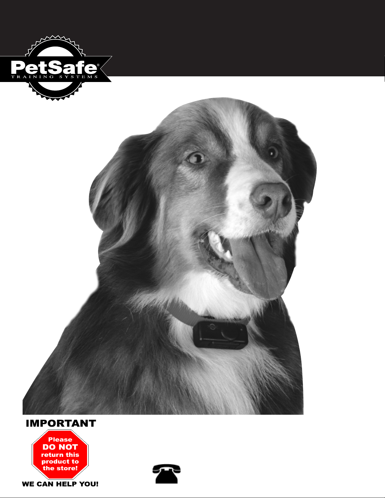
Layout –
Estimated time required: 30 minutes
1
Make a layout that is suitable
for your yard, graph paper is
provided on page 7. Refer to
sample layouts under "Laying
Out Your System"
Layout the Boundary Wire –
3
Estimated time required: 1 hour
Lay the boundary wire above
the ground according to your
layout. If more than 500 feet
of boundary wire is needed,
you may purchase more by
contacting customer service at
1-800-732-2677 or the retail
store where the system was
purchased. Insert stripped
wire ends into wire terminals
of the transmitter.
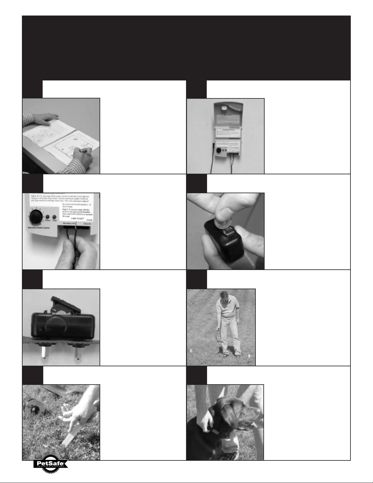
Locating and mounting the Fence Transmitter
– Estimated time required: 30 minutes
2
Mount the fence
transmitter in a dry location.
A mounting template is
located on the back cover of
this manual.
Remove the Battery Module from the Receiver –
Estimated time required: 5 minutes
4
Remove the battery module
by sliding the battery door
latch to the unlocked position.
A small coin may help. Now
push, or gently pry, the tab
on the battery door to lift the
module out of the receiver.
Insert the Battery Module into the Receiver –
Estimated time required: 5 minutes
5
Insert (2) 3-volt lithium
batteries into the module with
the positve(+) side on the
batteries facing the postive(+)
mark on the module.
Replace the battery modulePlace the module into the
receiver and slide the battery
door latch to the locked
position.
Burying the Wire and Placing the Flags –
Estimated time required: 2 to 4 hours
7
Cut a trench and bury the
boundary wire one to three
inches deep. Use a blunt tool
like a paint stick to push
the wire into the ground.
Place the ag in the ground
near the boundary where the
warning beep of the receiver
begins.
Testing –
Estimated time required: 15 minutes
6
Turn the transmitter on. Being
careful to not touch the probes,
approach the boundary wire holding
the receiver at knee level. If the
receiver beeps, the system is ready
to be tested. Continue to approach
the boundary wire with the receiver
around the entire layout. The
recommended initial distance
between the boundary wire and the
receiver is ve feet, and can be
adjusted on the transmitter.
What’s Next? – Read Training Manual
8
Estimated time required: 15 minutes
After these steps, familiarize
yourself further with the
transmitter and the receiver
by reading the manual. Read
the training manual. Place
the receiver collar on your pet
to start training.
2
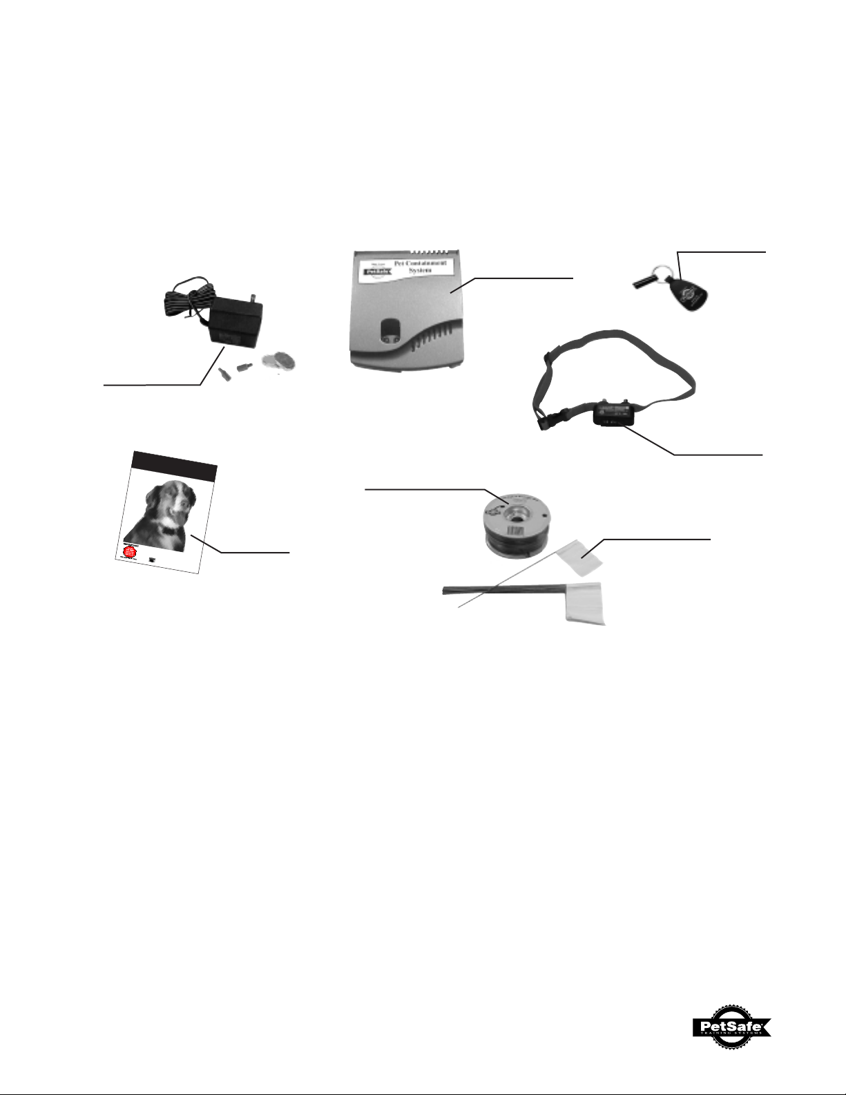
Components included with the system:
• Transmitter
• Receiver and Collar
• Batteries
• Owner's Manual
• Correction Key Ring
AC Adapter
& Batteries
PET CONTAINMENT
SYSTEM
Deluxe Owners Manual
Owner's
Should you encounter any problems with
refer to this instruction manual. Be sure
place for future reference.
If you should need assistance, call our toll free
1-800-732-2677
online at: www.petsafe.net
your new product, please
to file this manual in a safe
“HELP” line at:
Manual
Correction
Key Ring
Transmitter
Receiver
& Collar
500 feet
Boundary Wire
50 Boundary
Flags
Required, but may be sold separately:
• Wire nuts or Shrink Tubing
50 Boundary Flags
500 feet Boundary Wire*
*Use only Pet Containment System wire
Other items you may need:
• Straight edged spade or a lawn edger
• Wire stripping pliers
• Electrical tape
• Waterproofing compound (e.g. silicone caulk)
• Patching compound for your type of driveway or sidewalk
• PVC pipe if crossing a gravel or dirt driveway, pond or lake
• Pencil, Ruler or Protractor
• Drill with drill bit or masonry bit if drilling through wood or concrete
• Grounding rod and clamp
3
How the system works
The Pet Containment System consists of three primary components: FENCE TRANSMITTER,
RECEIVER, and BOUNDARY WIRE (antenna).
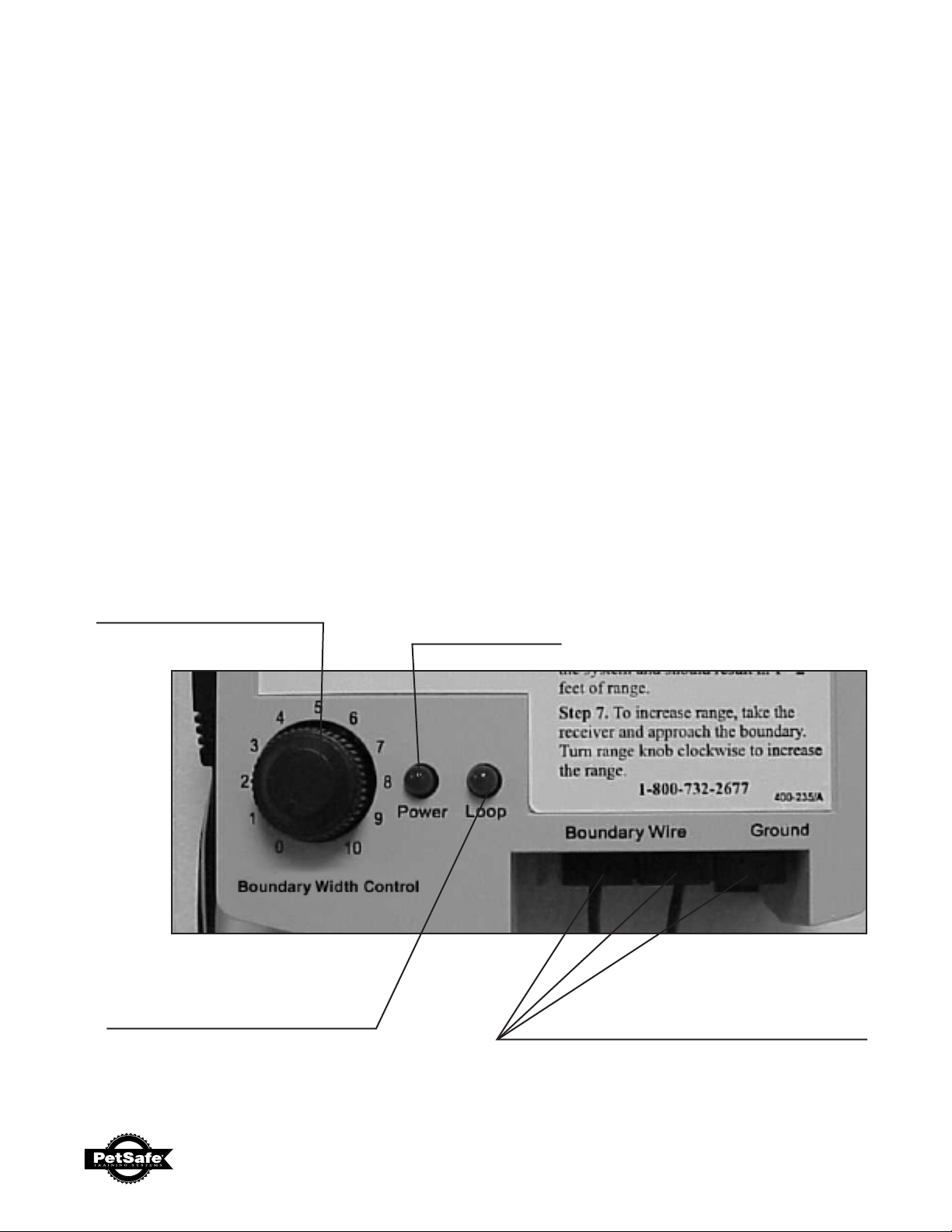
Fence Transmitter
The Deluxe Fence Transmitter has been designed to operate with a boundary wire up to 4000 feet
or 25 acres, and plugs into any standard outlet. The transmitter produces a very low frequency radio
signal. The magnetic field it generates is carried by the boundary wire which serves as an antenna.
The range or width of the magnetic field (i.e. the distance from the boundary wire to activate the
receiver) can be adjusted from a few feet up to thirty feet by the boundary width control knob located
on the transmitter.
Boundary Width Control
Width of the Correction &
Warning Boundary
Loop Indicators
Light On- No Problems
Light Off- Possible Broken Wire
Power Indicators
On/Off Light
Ground and
Boundary Terminals
Connect earth ground &
Boundary Wires here
4
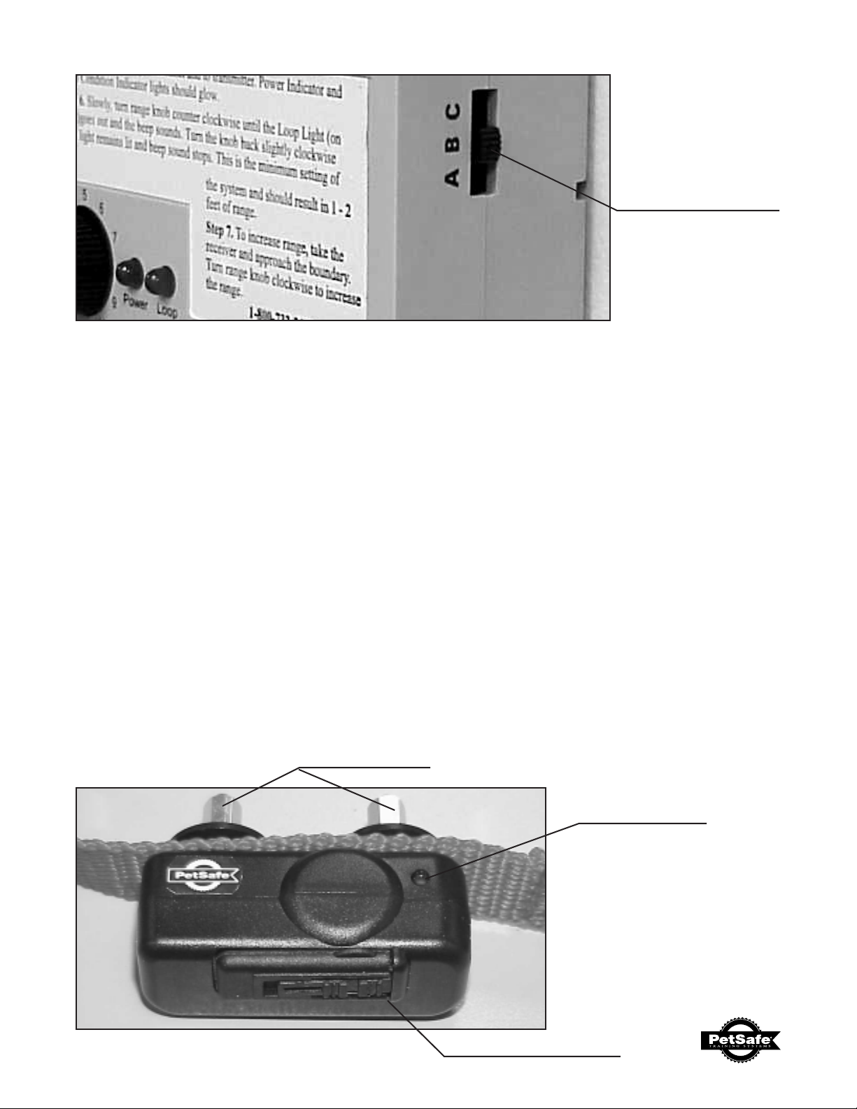
Range Switch
Setting "B" is used
for most yards.
Receiver with Collar
The UL-275 Receiver contains electronics to detect the magnetic eld carried by the containment boundary wire,
translates them, and delivers an electrical correction. The electrical correction is delivered through two contact
probes that touch the dogʼs neck.
There are two sets of contact probes that can be used on your receiver. The longer probes should be
used on dogs with long hair.
The UL-275 Receiver is enclosed in a waterproof case and is mounted on a polypropylene collar. The
collar will t a dog with a neck size varying from 9 to 22 inches.
The UL-275 Receiver contains a LED indicator light. The light acts as a low battery light and conrms
which one of ve correction levels are set.
The receiver is equipped with memory backup. After you replace the batteries in the receiver, you
will not have to reset the correction level. The LED indicator light will ash for the correction level
last set.
Contact Probes
Receiver LED
Indicator Light
Battery Door Latch
5
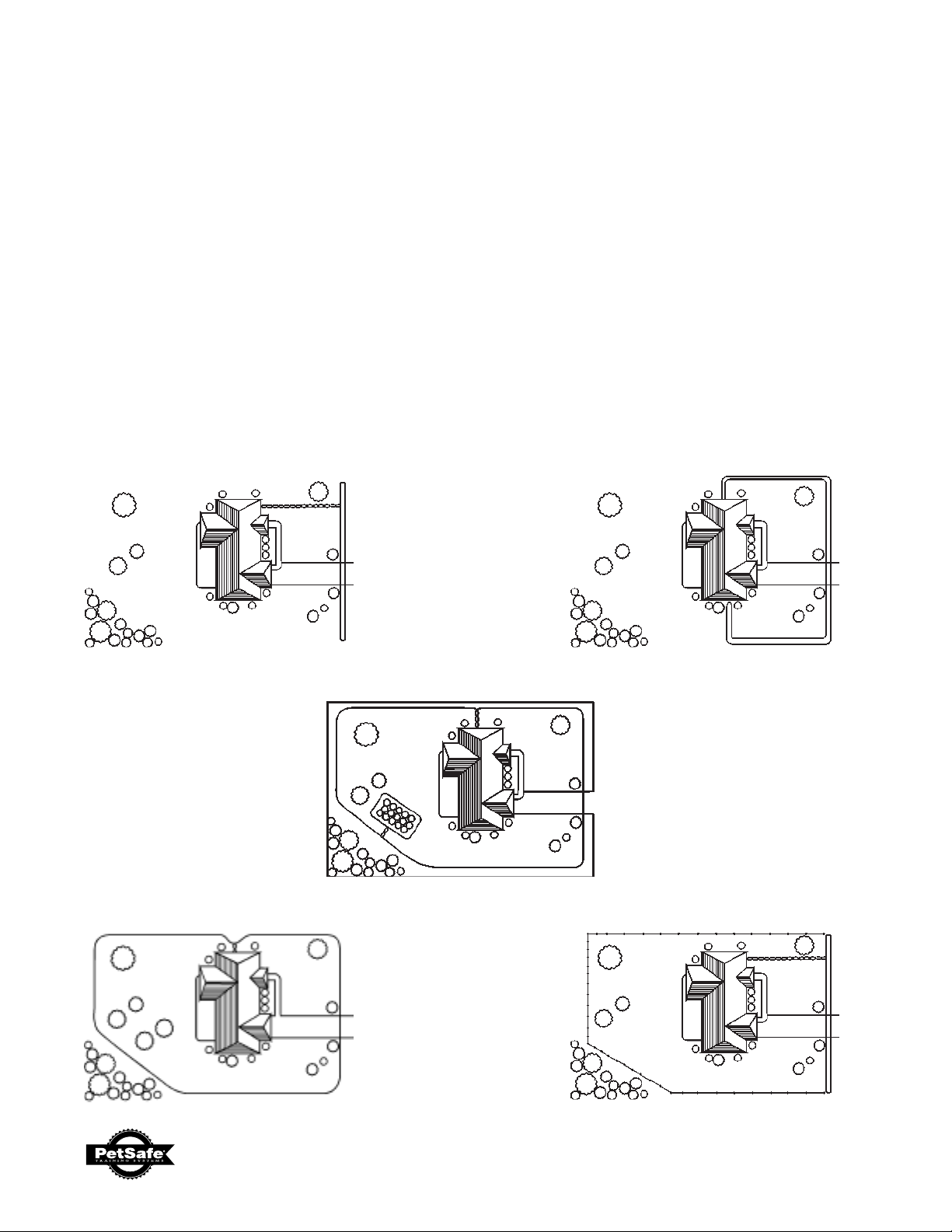
Laying out the System
Basic Planning Tips:
• The boundary wire must make a continuous loop back to the transmitter.
• Make a layout that is suitable for your yard, graph paper is provided on page 7. Sample layouts
are provided below.
• Always round the corners of your boundary with the wire. Sharp corners will distort the signal.
• Use a double loop layout to contain your pet on one side of your home. Ref: Fence front yard
only below.
• When installing a double loop, the wire must be spaced three to five feet apart to avoid canceling
the signal.
• The transmitter will transmit a signal from approximately two to thirty feet on either side of the
boundary wire. Be sure to leave enough area so that your dog can move about freely within
the safe area boundaries.
Sample Layouts:
FRONT BOUNDARY ONLY FENCE FRONT YARD ONLY
BASIC LOOP WITH GARDEN
FRONT OR BACK ACCESS FRONT BOUNDARY WITH
EXISTING FENCE
6
 Loading...