


12-Volt Negative Ground Installation Instructions
For Part Number: 1244A
CAUTION!!! Before installing, please read the following important information....
1.The Ignitor is designed for 12-Volt negative ground systems.
2.Leaving the ignition “ON” with the engine “OFF” for an extended period could result in permanent damage to the Ignitor.
3.See Chart on back page for coil recommendations.
4.Four & Six cylinder engines require a minimum of 3.0 ohms of primary resistance. Do not remove resistors if the coil primary resistance is less than 3.0 ohms.
5.If your Ignition coil has the recommended primary resistance, remove or bypass all external resistors.
6.The Ignitor is compatible as a trigger for most electronic boxes.
DISASSEMBLY
1.PRIOR TO INSTALLATION TURN IGNITION SWITCH OFF OR DISCONNECT THE BATTERY
2.Remove the distributor cap, and rotor. Do not disconnect spark plug wires. Examine cap and rotor for wear or damage. Replace as needed.
3.Rotor tension spring must be removed from distributor shaft in order to remove dust shield.
4.Disconnect the point wire from the negative (-) terminal of the coil.
5.Remove the point wire, point, and condenser from the distributor. The Ignitor does not require any modification to the distributor. Therefore the point, condenser and hardware can be used as backup.
6.Clean all dirt and excess oil from the breaker plate and point cam.
IGNITOR INSTALLATION
1.Determine the rotation of your distributor rotor. The Ignitor can be installed in clockwise or counter clockwise positions.
2.Install Ignitor plate using the screw hole stamped for the correct rotation. “CC” indicates the correct screw hole for counter clockwise rotation. “C” indicates the correct screw hole for clockwise rotation.
3.Fasten the Ignitor plate to the distributor beginning with the correctly stamped screw hole. Two screws must be used.
4.Install grommet into hole in the side of the distributor body. The wire length inside the distributor can be adjusted by gently pulling one wire at a time through the grommet. CAUTION: care must be taken to insure wires do not interfere with moving parts.
5.Install magnet sleeve over distributor shaft, onto point cam. Rotate sleeve until a slight locating position is felt before applying pressure. With sleeve lined up on point cam, press down firmly insuring sleeve is fully seated.
6.Module and magnet sleeve air gap is not adjustable.
7.Reinstall dust shield, rotor spring tension clip, and rotor. NOTE: SOME APPLICATIONS REQUIRE THE
INSTALLATION OF THE DUST SHIELD TO INSTALL THE DISTRIBUTOR CAP. THE CENTER HOLE OF THE DUST SHIELD MUST BE ENLARGED TO CLEAR THE MAGNET SLEEVE.
8.Install distributor cap. Make sure all spark plug wires are securely attached.
9.See Wiring Instructions.
Ignitor Installed in the Counter Clockwise |
|
For CLOCKWISE (C) |
|
ROTATING DISTRIBUTORS |
|
Position (CC) |
|
|
|
Use mounting holes indicated |
|
(See arrows for clockwise installation.) |
|
|
|
by the arrows. |
|
|
|
|
|
|
|
909-599-5955 www.pertronix.com
Page 1 of 4
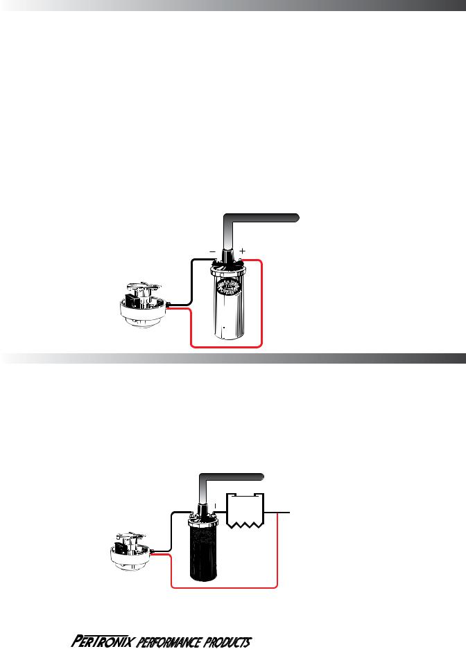
A.Recommended Wiring Installation:
The Ignitor ignition can be used in conjunction with most ignition coils rated at 1.5 ohms of primary resistance on eight cylinder engines and 3.0 ohms on four and six cylinder engines. For optimum performance purchase and install the recommended Flamethrower high performance coil.
Many vehicles came equipped with ballast resistor or resistance wire. To achieve optimum performance from the Ignitor ignition system, we recommend the removal of these components.
•To remove a ballast resistor, (normally white ceramic blocks 3 to 4 inches long), disconnect all wires on both ends of the ballast resistor. Remove the resistor from the vehicle and splice the disconnected wires together at a single point.
•To remove a resistance wire, trace the coil power wire, which was previously connected to the positive coil terminal, back to the fuse block. Bypass this wire with a 12-gauge copper stranded wire.
1.Attach the black Ignitor wire to the negative coil terminal. (See Figure A)
2.Attach the red Ignitor wire to the positive coil terminal. (See Figure A)
3.Check to insure that the polarity is correct, and that all connections are tight.
4.Re-connect the battery.
5.Start the engine and allow it to reach normal operating temperature. Check ignition timing, and adjust to the desired setting.
COIL WIRE


 TO IGNITION BLACK WIRE


(FIGURE A)
RED WIRE
B. Alternative Wiring Installation:
The Ignitor can also be installed in applications retaining the ballast resistor or resistance wire.
1.Attach the Ignitor black wire to the negative coil terminal. (See Figure B)
2.Attach the Ignitor red wire to the ignition side of resistance, or any 12 volt ignition power source. (See Figure B)
3.Check to insure that the polarity is correct, and that all connections are tight.
4.Re-connect the battery.
5.Start the engine and allow it to reach normal operating temperature. Check ignition timing, and adjust to the desired setting.
COIL WIRE
BALLAST RESISTOR
TO IGNITION SWITCH
BLACK WIRE
(FIGURE B)
RESISTANCE WIRE
RED WIRE
909-599-5955 www.pertronix.com
Page 2 of 4
 Loading...