

Page 1

PERLICK CR24 COLUMN REFRIGERATION
PLANNING GUIDE
Page 2
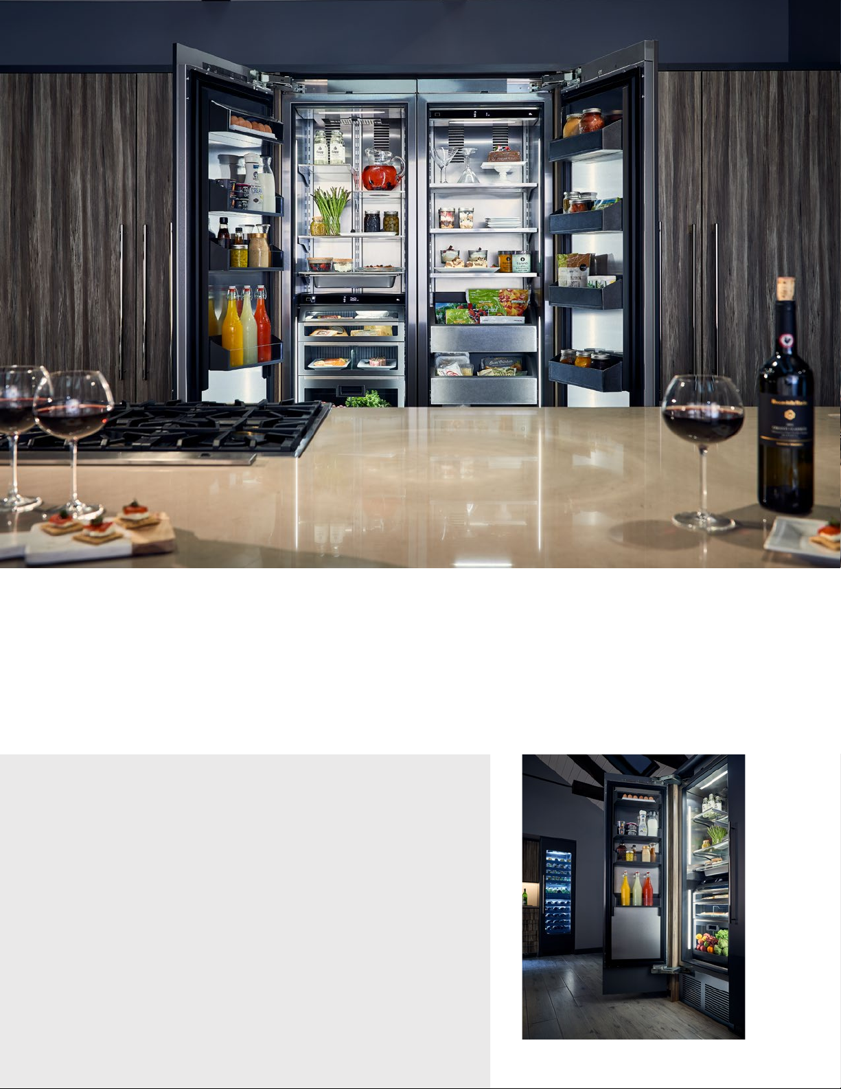
ALL THE DELICIOUS DETAILS OF THE NEW PERLICK CR24 COLUMN REFRIGERATION
Enjoy the flexibility of Perlick column refrigeration by mixing and matching units to create
custom storage for food, wine and beverages. Columns can be installed individually or installed
side-by-side in a pair or more to serve any sized kitchen.
The following provides installation guidance for planning your space. For complete installation
instructions, please refer to the column installation guide on perlick.com/residential.
3 CR24 MODEL LIST
3 CR24 ACCESSORY LIST
4 DOOR OVERLAY TEMPLATES
4 OVERLAY, SOLID DOOR
5 OVERLAY, GLASS DOOR
6 INSTALLATION
7 OPENING DIMENSIONS, SINGLE INSTALL
7 OPENING DIMENSIONS, DUAL INSTALL
8 OPENING DIMENSIONS, TRIPLE INSTALL
Page 3
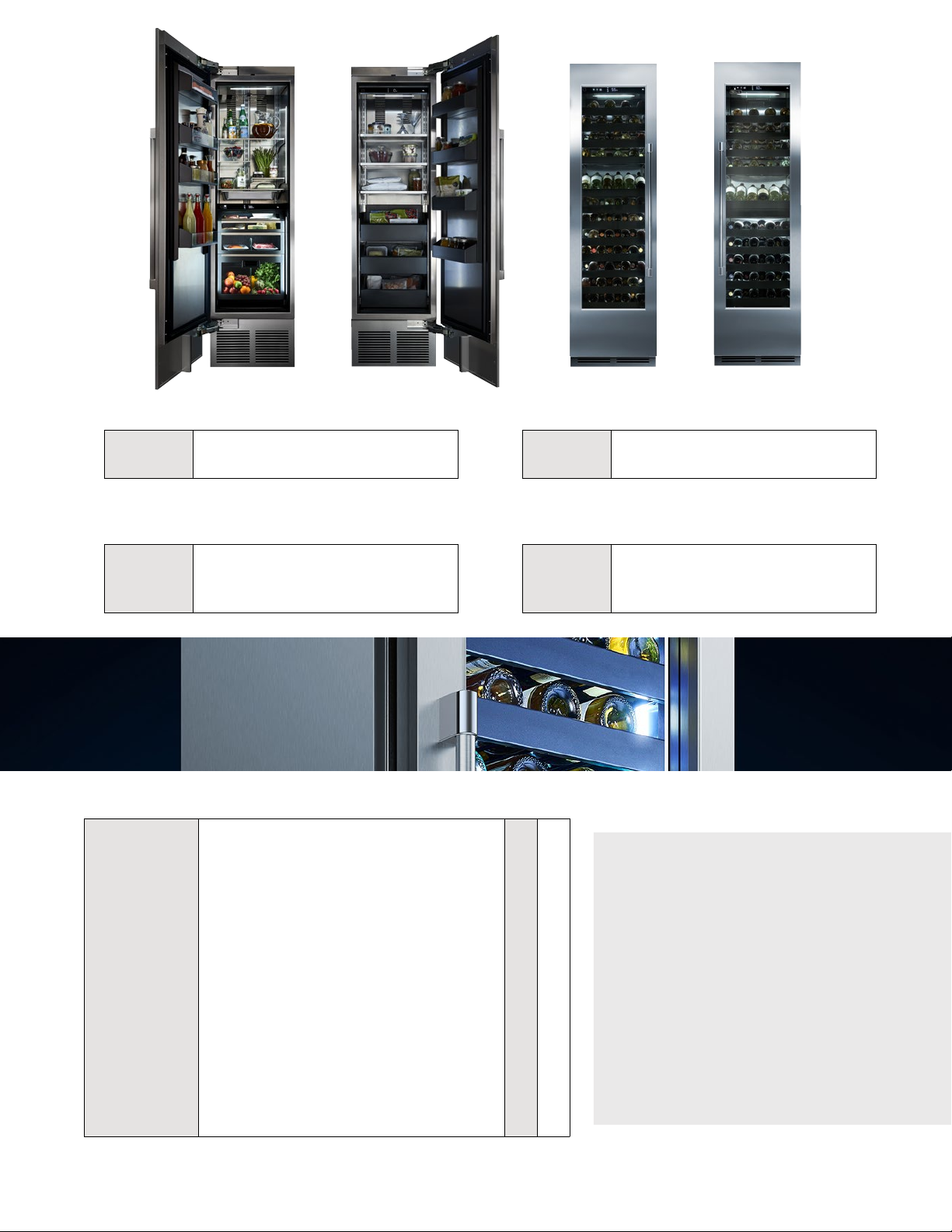
CR24R COLUMN REFRIGERATOR
CR24F COLUMN FREEZER
CR24W COLUMN SINGLE-ZONE WINE RESERVE
CR24D COLUMN DUAL-ZONE WINE RESERVE
CR24R COLUMN REFRIGERATOR
CR24R-1-2L All Refrigerator, Solid Overlay Door, Hinged Le
CR24R-1-2R All Refrigerator, Solid Overlay Door, Hinged Right
CR24W COLUMN WINE RESERVE,
SINGLE ZONE
CR24W-1-4L
CR24W-1-4R
CR24 COLUMN REFRIGERATION ACCESSORIES A B
CR-ACC-24SEPR/L
CR-ACC-D1
CR-ACC-D1N
CR-ACC-D2N
CR-ACC-TRIM
CR-SS-24PDL/R
CR-SG-24PDL/R
CR-PRO-HANDLE
Wine Reserve, Single Zone, Glass Overlay Door,
Hinged Le
Wine Reserve, Single Zone, Glass Overlay Door,
Hinged Right
Stainless Steel Exterior Finishing Panels (for le or right
side of exposed column)
Dual Installaon Kit (Handle-to-Handle)-(includes an-
sweat heat mat)
Dual Installaon Kit (Handle-to-Handle)-(less an-sweat
heat mat)
Dual Installaon Kit (Handle-to-Handle)-(less an-sweat
heat mat)
Built-in Trim Kit (le and right nish trim kit for built-in
columns)
Stainless Steel Solid Door Panel w/Two Tone Perlick Pro
Handle (le or right hinge - available for 4” or 6” toe kicks)
Stainless Steel Glass Door Panel w/Two Tone Perlick Pro
Handle (le or right hinge - available for 4” or 6” toe kicks)
Two Tone Perlick Pro Handle (when sold separately for use
with customer-supplied door panel)
A FACTORY INSTALLED B FIELD INSTALLED
CR24F COLUMN FREEZER
CR24F-1-2L All Freezer, Solid Overlay Door, Hinged Le
CR24F-1-2R All Freezer, Solid Overlay Door, Hinged Right
CR24D COLUMN WINE RESERVE,
DUAL ZONE
CR24D-1-4L
CR24D-1-4R
•
•
•
•
•
•
•
•
Wine Reserve, Dual Zone, Glass Overlay Door,
Hinged Le
Wine Reserve, Dual Zone, Glass Overlay Door,
Hinged Right
HEAT MAT REQUIREMENTS
FOR MULTI-UNIT
INSTALLATIONS
If installing a freezer side-byside with a refrigerator or wine
column, a dual installation kit
(CR-ACC-D1) is required.
The heat mat is installed
between the units to prevent
condensation and does not
require a dedicated outlet.
3
Page 4
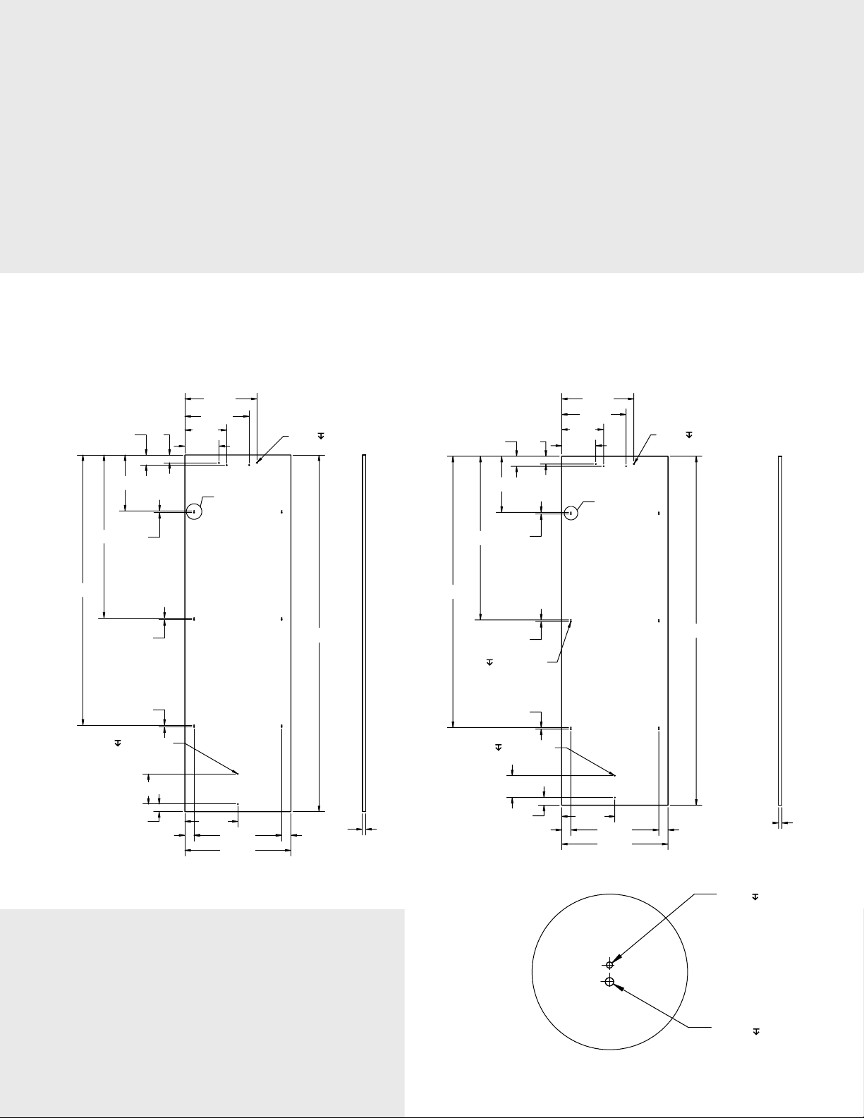
DOOR OVERLAY PANELS
Perlick CR24 column refrigeration comes ready to accept a customer-supplied door overlay panel
and customer-supplied handle. A minimum 5/8” thick panel is required, however, the thickness can
increase provided the panel does not exceed a weight of 65 lbs. The depth of each model is 24”
without a finished overlay, so be sure to allow for panel thickness when planning the finished
opening depth.
This guide includes solid and glass door templates with 4” and 6” toe kicks. Please note that when
installing a panel thicker than 3/4”, a 90° stop may be required to prevent damage to both the
unit and surrounding cabinetry.
SOLID DOOR OVERLAY TEMPLATE
FOR 4” TOE KICK
SOLID DOOR OVERLAY TEMPLATE
FOR 6” TOE KICK
Measurements shown in inches (“) Measurements shown in inches (“)
Ø 1/8 1/2 (4X)
79-7/8
2-1/4
12-1/2
36-1/2
60-1/2
Ø 3/16 1/4 (12X)
3/8
3/8
3/8
1-3/4
9-3/8
7-5/8
60-1/2
36-1/2
2-1/4
12-1/2
3/8
3/8
3/8
1-3/4
16-1/8
14-3/8
9-3/8
7-5/8
A
16-1/8
14-3/8
Ø 1/8 1/2 (4X)
B
7 7 -7/ 8
Ø 1/8 1/4 (2X)
6-3/4
1-11/16
2-1/16
11-7/8
19-5/8
23-3/4
REVEALS
Reveals between panels can vary — 1/8”
is the minimum. As reveals between
cabinetry and the unit decrease, severe
finger pinching can occur while the
door is closing.
4
2-1/16
3/4
Ø 1/8 1/4 (2X)
4 -7/ 8
1-3/4
2-1/16
OVERLAY CLIP
DETAIL A & B
11-7/8
19-5/8
23-3/4
2-1/16
3/4
Ø 1/8 1/2 (6X)
Ø 3/16 1/2 (6X)
Page 5
GLASS DOOR OVERLAY TEMPLATE
FOR 4” TOE KICK
GLASS DOOR OVERLAY TEMPLATE
FOR 6” TOE KICK
Measurements shown in inches (“) Measurements shown in inches (“)
60-1/2
79-7/8
2-1/4
12-1/2
36-1/2
6-3/4
1-11/16
1-3/4
3/8
3/8
3/8
3-3/8
2-1/16
9-3/8
7-5/8
16-1/8
14-3/8
A
11-7/8
19-5/8
23-3/4
Ø 1/8 1/2 (4X)
6-5/8
Ø 1/8
1/2 (12X)
60
CUTOUT
17 CUTOUT
Ø 1/8 1/2 (4X)
16-1/8
14-3/8
9-3/8
1-3/4
7 7- 7/8
36-1/2
60-1/2
2-1/4
4 -7/ 8
1-3/4
12-1/2
3/8
3/8
3/8
3-3/8
2-1/16
7-5/8
B
11-7/8
19-5/8
23-3/4
3/4
Ø 1/8 1/2 (4X)
6-5/8
Ø 1/8 1/2
(12X)
60
CUTOUT
17 CUTOUT
Ø 1/8 1/2 (2X)
3/4
SCREW ZONE
FOR DOOR OVERLAY
TEMPLATES
Shaded areas (shown right)
should provide enough
thickness for wood screws for
overlay attachment bracket.
Door handle must be
attached to overlay panel
prior to installing panel onto
the unit. Mounting screws for
the handle should be
recessed or countersunk into
the back side of the overlay
panel.
69-1/2
3
66
3-1/16
3-1/4
23-3/4
3-1/16
3/4
C
L
11-3/8 1
Measurements shown in inches (“)
5
Page 6
INSTALLING PERLICK COLUMN REFRIGERATION
Designed specifically to be integrated into cabinetry, Perlick column refrigeration brings
commercial-grade performance and preservation to any style of kitchen. Columns can be installed
separately, or in side-by-side installations to create custom modular refrigeration.
The following diagrams show various ways to install Perlick column refrigeration and provide
information on producing custom overlay panels.
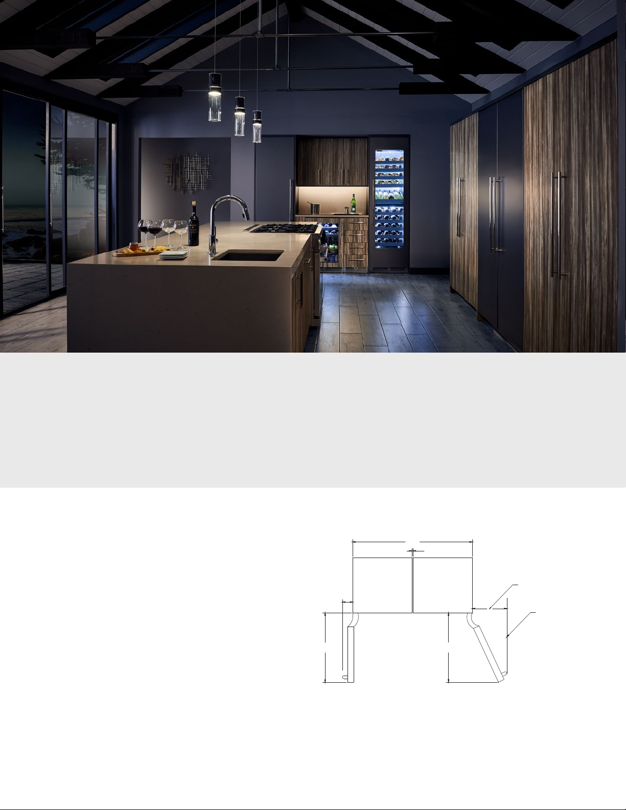
ADJACENT WALL MINIMUM
CLEARANCE REQUIREMENTS
If installing column next to adjacent wall,
48
take care to observe minimum required
clearances to avoid inteference when
opening the door. Please note the clearances
indicated are based on a standard 3/4” thick
door panel and Perlick Two Tone Pro Handle
4-1/8
13-13/16
ADJACENT WALL
OR STRUCTURE
(CR-PRO-HANDLE). Varying door depths
and dimensions of customer-provided
handle may change the required dimensions.
27-13/16
STRUCTURE
CLEARANCE
90° OPEN
27-3/4
STRUCTURE
CLEARANCE
115° FULLY OPEN
A 90° hinge stop pin (included with unit)
can be installed to prevent the door from
Measurements shown in inches (“)
opening beyond 90°. Pin must be installed
prior to full integration. See installation
manual for instructions.
6
Page 7
OPENING DIMENSIONS FOR A
SINGLE UNIT
Perlick columns allow you the
freedom to install refrigeration
separately anywhere in the kitchen.
Columns are designed to be
integrated into cabinetry, however,
factory installed stainless steel side
panels are available for installations
where the side of the column is
exposed.
SIDE
WALL
CABINET
84
24-3/4
24 TO FRONT
OF DOOR FRAME
23-3/4
OVERALL
25
24
22-1/8 TO
CABINET
OVERALL
83-7/8 TO
TOP OF
OVERLAY
3/4 OVERLAY
4 - 6
TOE KICK
DOOR
24
4
FRAME
FACE
21-9/16 TO
GRILL
Measurements shown in inches (“)
OPENING DIMENSIONS FOR INSTALLING TWO UNITS SIDE-BY-SIDE
Perlick columns can be installed side-by-side in a variety of configurations provided the following
installation specifications are met. Hinge/handle locations and adjacency to walls/structure must
be taken into consideration during the planning process. Choose your desired column
configuration on the left and match to the opening (blue label) drawing on the right for the
proper cutout dimensions (applies to units installed both with or without dual installation kit.)
48
1/2
A. HANDLE TO HANDLE
49-1/2
48
1/2
B. HINGE TO HINGE
84
48-1/2
(A & B)
OPENING
84
50
(C)
OPENING
2
C. HANDLE TO HINGE*
90°
*90° HINGE PIN
Doors open to 105°. The
90° hinge pin stop can be
installed. If hinge pin is
installed, all gaps between
cabinets can be 1/2”.
If using hinge pins on all
units, refer to Opening
Dimensions A & B.
12
10
12
12
10
12
Measurements shown in inches (“)
7
Page 8

OPENING DIMENSIONS FOR INSTALLING THREE UNITS SIDE-BY-SIDE
As with dual installations, choose your desired column configuration below and match to the
opening (blue label) drawing for the proper cutout dimensions (applies to units installed both
with or without dual installation kit.)
For installations involving more than three cabinets, combine the opening dimensions for the
openings which correspond to the combined Hinge and Handle combinations shown in this guide.
75-1/4
49-1/2”
2
D. HINGE CONFIGURATIONS
LEFT - LEFT- LEFT
RIGHT - RIGHT - RIGHT
73-3/4
2
F. HINGE CONFIGURATIONS
LEFT - LEFT - RIGHT
RIGHT - RIGHT - LEFT
76
2
No cabinets physically joined
together in this conguraon
1/2
(2) cabinets physically joined
together in this conguraon
72-1/4”
48”
1/2 1/2
E. HINGE CONFIGURATIONS
LEFT - RIGHT- LEFT
RIGHT - LEFT - RIGHT
73-3/4
1/2 2
G. HINGE CONFIGURATIONS
RIGHT - LEFT - LEFT
LEFT - RIGHT - RIGHT
73
All cabinets physically joined
together in this conguraon
(2) cabinets physically joined
together in this conguraon
90°
*90° HINGE PIN
Doors open to 105°. The
90° hinge pin stop can be
installed. If hinge pin is
installed, all gaps between
cabinets can be 1/2”.
If using hinge pins on all
units, refer to Opening
Dimensions E.
74-1/2
84
(D)
OPENING
84
38
12
10
12
36-1/2
12
10
(E)
OPENING
(F & G)
37-1/4
OPENING
10
12
84
12
12
Measurements shown in inches (“)
Visit perlick.com/residential for the latest information on how to install Perlick CR24 column
refrigeration. To purchase Perlick accessories, contact your local Perlick Residential dealer.
© 2018 Perlick Corporation
8
FORM NO. Z2549
REV. D-08/03/2018
 Loading...