

Page 1
INSTALLATION AND OPERATION INSTRUCTIONS
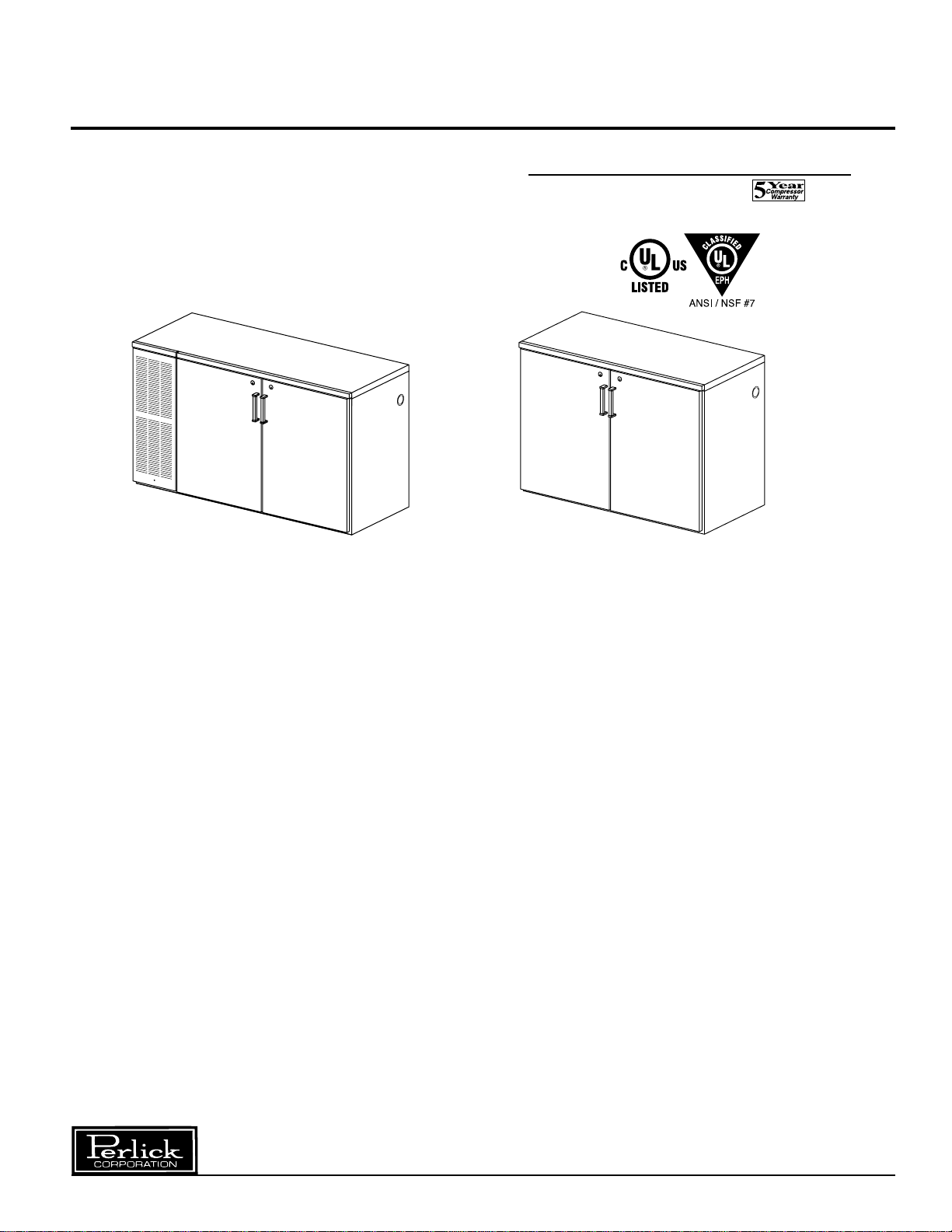
CUSTOM BACK BAR CABINET — SELF CONTAINED AND REMOTE
MODEL NOS.
BS Series
BR Series
BS Series
IMPORTANT INFORMATION
Fill out the enclosed warranty card and mail to the
Perlick Corporation to register the warranty. If the
card is not returned, the warranty period will begin
from the date the equipment is shipped from the
factory.
This manual has been prepared to assist you in the
installation of your Cabinet and to acquaint you with
its operation and maintenance.
We dedicate considerable time to ensure that our
products provide the highest level of customer
satisfaction. If service is required, your dealer can
provide you with a list of qualified service agents. For
your own protection, never return merchandise for
credit without our approval.
We thank you for selecting a Perlick product and
assure you of our continuing interest in your
satisfaction.
BR Series
Table of Contents
PREPARING THE CABINET
Specifications......................................................2,3
List of Included Parts.............................................4
Tools Required.......................................................4
Plumbing................................................................4
Electrical................................................................4
Uncrating and Inspection .......................................4
Placing the Cabinet ...............................................4
Leveling the Cabinet ..............................................4
Installing Casters or Legs .....................................4
Installing the Base Plate........................................4
Refrigeration and Temperature Control.................5
Cleaning the Cabinet.............................................5
Replacement Parts................................................6
Cleaning Stainless Steel........................................7
Wiring Diagram......................................................8
WARNING: When lifting, the full weight of the
cabinet must be supported. Lift from the cabinet
base and not from the top. Improper lifting can
result in severe damage to the cabinet.
8300 West Good Hope Road • Milwaukee, WI 53223 • Phone 414-353-7060 • Fax 414-353-7069
Toll Free 800-558-5592 • E-Mail: Perlick@Perlick.com • www.Perlick.com
Form No. Z2083A
Rev. 08.03.04
Page 2
Installation and Operating Instructions
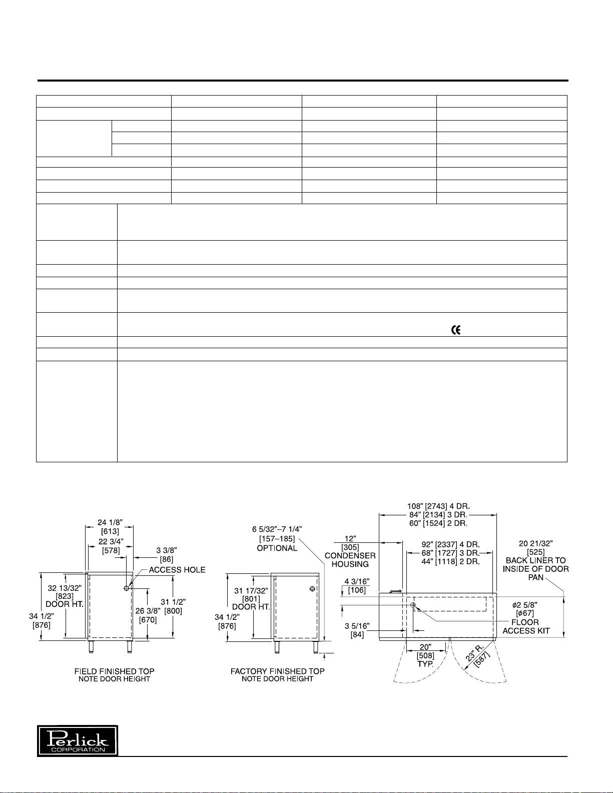
Sizes and Specifications, Standard Back Bar Cabinets – Self Contained
MODEL NOS. BS2D BS3D BS4D
NUMBER OF DOORS 2 3 4
CABINET Length 60” (1524) 84” (2134) 108” (2743)
DIMENSIONS Depth 24
(mm) Height 34
CASE CAPACITY* 12.9 20.4 27.7
CONDENSING UNIT H.P.
RUNNING LOAD - AMPS 6.3 8.1 8.3
SHIPPING WIEGHT lbs. (kg.) 380 (172) 490 (222) 630 (286)
INTERIOR Door Sill: 14 gauge stainless steel supported by a 12 gauge interior angle bracket running entire length of
cabinet. Door Pan: High strength polystyrene. Floor Pan: Stainless steel. Walls & Ceiling: Stainless steel interior.
Includes pilasters & (2) vinyl coated shelves per door. Includes interior light.
EXTERIOR Black: Front and sides are black painted steel. Base panel stainless steel. Back and top unfinished galvanized steel.
Stainless Steel: Front, base panel and sides are stainless steel. Back and top are galvanized steel.
DOOR HINGING Concealed hinging as illustrated. For special hinging, specify left to right.
DOOR HARDWARE Door handles: Black vinyl with chrome ends. Lock finish: chrome.
REFRIGERATION R-134a capillary tube-type. Aluminum fin and copper tube evaporator coil. Adjustable temperature control. Self-
defrosting, pull-out condensing unit for service and cleaning. Compressor left.
ELECTRICAL 115 Volt, 60 Hz., 1 phase AC. Furnished with three-prong, six foot rubber cord. Contact Perlick for other
voltage/frequency requirements. Also available in 230 Volt, 50 Hz., 1 phase AC. Carries marking of conformity.
PLUMBING None required. Condensate evaporates automatic.
INSULATION Foamed-in place polyurethane; 2" walls, 1
OPTIONAL • Leg set • Stainless steel top Door Finishes
ACCESSORIES & • Tapping kit • Stainless steel ends Black powder coated
MODIFICATIONS • Laminated top • Caster sets Stainless steel
• Laminated ends • Base plates Glass door with black frame
• Laminated grille • Floor access kit Glass door with stainless steel frame
• Compressor right Glass door with laminated frame
• Brass hardware Laminated doors (customer’s choice)
1
/8” (613) 241/8” (613) 241/8” (613)
1
/2” (876) 341/2” (876) 341/2” (876)
1
/4
1
/2" top and floor.
1
/3
1
/3
Prepared for field lamination
*Based on 12 oz. export bottles.
Form No. Z2083A
Rev. 08.03.04
Perlick is committed to continuous improvement. Therefore, we reserve the right to change specifications without prior notice.
2
Page 3
Installation and Operating Instructions
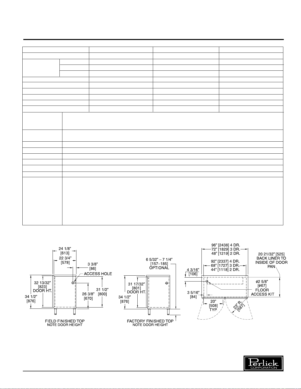
Sizes and Specifications, Standard Back Bar Cabinets – Remote
MODEL NOS. BR2D BR3D BR4D
NUMBER OF DOORS 2 3 4
CABINET Length 48” (1219) 72” (1829) 96” (2438)
DIMENSIONS: Depth 24
(mm) Height 34
CASE CAPACITY* 12.9 20.4 27.7
EVAPORATOR BTU/HR 1800 2200 2600
RUNNING LOAD - AMPS .9 .9 .9
LIQUID INLET LINE SIZE
SUCTION LINE SIZE
SHIPPING WIEGHT lbs. (kg.) 250 (114) 310 (141) 350 (159)
INTERIOR Door Sill: 14 gauge stainless steel supported by a 12 gauge interior angle bracket running entire length of
cabinet. Door Pan: High strength polystyrene. Floor Pan: Stainless steel. Walls & Ceiling: Stainless steel interior.
Includes pilasters & (2) vinyl coated shelves per door. Includes interior light.
EXTERIOR Black: Front and sides are black painted steel. Base panel stainless steel. Back and top unfinished galvanized steel.
Stainless Steel: Front, base panel and sides are stainless steel. Back and top are galvanized steel.
DOOR HINGING Concealed hinging as illustrated. For special hinging, specify left to right.
DOOR HARDWARE Door handles: Black vinyl with chrome ends. Lock finish: chrome.
REFRIGERATION Evaporator can operate with most common refrigerants—exception NH
ELECTRICAL 115 Volt, 60 Hz., 1 phase AC. Contact Perlick for other voltage/frequency requirements.
PLUMBING Independent floor drain or condensate pan evaporator is required. Optional 2
INSULATION Foamed-in place polyurethane; 2" walls, 1
OPTIONAL • Leg set • Stainless steel top Door Finishes
ACCESSORIES & • Tapping kit • Caster sets Black powder coated
MODIFICATIONS • Laminated top • Base plates Stainless steel
• Laminated ends • Floor access kit Glass door with black frame
• Laminated grille • R22 (condensing unit Glass door with stainless steel frame
• Brass hardware assembly with pressure Glass door with laminated frame
• Stainless steel ends control) Laminated doors (customer’s choice)
1
/8” (613) 241/8” (613) 241/8” (613)
1
/2” (876) 341/2” (876) 341/2” (876)
1
/2” O.D.
3
/8” O.D.
1
/2" top and floor.
1
/2” O.D.
3
/8” O.D.
1
/2” O.D.
3
/8” O.D.
3
1
/8” I.D. floor access kit — left rear corner.
Prepared for field lamination
*Based on 12 oz. export bottles.
Perlick is committed to continuous improvement. Therefore, we reserve the right to change specifications without prior notice.
3
Form No. Z2083A
Rev. 08.03.04
Page 4

General Information – Standard Back Bar Cabinets
Parts List
■ (2) Shelves Per Door.
■ Interior Lights.
■ Shelf Clips.
Tools Required
■ #2 Phillips Screwdriver.
■ 10” Crescent Wrench.
3
■
/8” Nut driver.
9
■
/16” Allen Wrench.
■ Power Drill or Driver
(for leg installation)
.
Plumbing
Self-contained models: none required.
Condensate evaporates automatically.
Electrical
The cabinet must be connected to a separately
fused power source (see electrical specification
plate) and grounded in accordance with National
and Local Electrical Codes. Caution: Do not
attempt to operate the equipment on any other
power source than that listed on the Electrical
Specification plate.
Placing the Cabinet
Push the cabinet into place using rollers when
necessary. Important: Proper air flow around the
condensing unit is necessary for efficient operation.
Never obstruct the air flow in and out of the
condensing unit compartment.
Leveling the Cabinet
When the cabinet is in place, check installation with
a carpenter’s level. When perfectly level,
accumulated water will drain out. Aslight pitch to
the drain side will not harm the cabinet. Water
may accumulate if cabinet is pitched to the
opposite side.
Installing Casters or Legs (Optional)
Attach casters or legs to cabinet bottom in holes
provided. Use the supplied
hex head self-tapping machine screws.
1
/4”- 20 x 3/4”
Installing Base Plate (Optional)
Attach brackets to cabinet bottom in holes provided.
Use #10 self-drilling hex sheet metal screws
(see separate instructions). When returning cabinet
to upright position, be careful not to bend brackets.
Uncrating and Inspection
Remove all crating material before operating.
Carefully inspect cabinet for hidden damage. If
damage is discovered, file your claim immediately
with the transportation company. Perlick is
not responsible for damage in transit.
Form No. Z2083A
Rev. 08.03.04
Perlick is committed to continuous improvement. Therefore, we reserve the right to change specifications without prior notice.
4
Page 5

Preparing the Cabinet for Use – Standard Back Bar Cabinets
Refrigeration andTemperature Control
The Back Bar Cabinet is equipped with a heavyduty refrigeration system designed to automatically
maintain a storage temperature of 36-41 degrees F.
The control is factory set at 38 degrees F.
To Adjust the Temperature:
The temperature control is inside the cabinet on
the right-hand side of the evaporator fan panel
assembly. You will need a screwdriver to turn the
adjusting screw. Make small adjustments until the
desired temperature is achieved.
Cleaning the Cabinet:
■ Disconnect all power prior to cleaning.
■ Use a mild detergent and water to clean the
inside and outside of the cabinet.
■ Inspect and clean the fan, evaporator coil and
light channel areas as necessary.
■ Dry thoroughly.
CAUTION: Never use a scouring pad or abrasive
cleaners.
Cleaning the Condenser:
Use a stiff brush to clean the dirt from the front
surface of the condenser. Keeping the condenser
free from dust and dirt will ensure efficient
operation.
CAUTION: Do not bend the fins while brushing the
front of the condenser.
■ Colder Temperatures: Turn the adjusting screw
clockwise (to the right)
■ Warmer Temperatures: Turn the adjusting
screw counterclockwise (to the left.)
The condenser fan motor turns off and on with the
condensing unit. The evaporator fan motor runs
continuously. The fan motors are lifetime lubricated
and will require no oiling.
NOTE: Cabinet temperatures lower than 34° will not
allow for proper defrosting of the evaporator coil. If
defrosting is necessary, turn the control knob to the
OFF position until coil is defrosted.
Perlick is committed to continuous improvement. Therefore, we reserve the right to change specifications without prior notice.
5
Form No. Z2083A
Rev. 08.03.04
Page 6

Replacement Parts – Standard Back Bar Cabinets
MODEL NOS. BS2D BS3D BS4D
BR2D BR3D BR4D
All Models Serial Numbers Above 500,000
CABINET HINGE
Right hinge set (SS or Lam tops only) 63407R 63407R 63407R
Left hinge set (SS or Lam tops only) 63407L 63407L 63407L
Top hinge rail for door cabinet
(Unfinished top)
Shelf kit, end compartment 57928 57928 57928
Shelf kit, center compartment N/A 57929 57929
Left or right shelf 62307-2 62307-2 62307-2
Center shelf N/A 62308-2 62308-2
Vertical partition 61830-1 61830-1 61830-1
Shelf clip C15875 C15875 C15875
Pilaster strip C19271-1 C19271-1 C19271-1
Magnetic gasket for wood doors 62581A1 62581A1 62581A1
Magnetic gasket for metal or
glass doors
Self Contained Models Only
Condensing Units
(2 door models)
Condensing unit 1/4 h.p. 115 volt, 60 hz. C22647 N/A N/A
Condensing unit
Compressor
(model UFI10HBX)
(model FFI10HBX)
Fan motor assembly 215315009 N/A N/A
Condenser coil 15352019 N/A N/A
Terminal board 219101538 N/A N/A
Overload protector MRT20AGK5590 N/A N/A
Relay 21351619 N/A N/A
Capacitor
Condensing Units
(282-339 MFD. 155V)
(3 & 4 door models)
Condensing unit 1/3 h.p. 115 volt N/A C22646 C22646
Condensing unit
Compressor
(model UFI12HBX)
(model FFI12HBX)
Fan motor assembly N/A 215315009 215315009
Condenser coil N/A 15352019 15352019
Terminal board N/A 219101538 219101538
Overload protector N/A MRT22AFZ5590 MRT22AFZ5590
Relay N/A 21351619 21351619
Capacitor
(282-339 MFD. 155V)
Condenser housing back panel 60976-1G 60976-1G 60976-1G
Grille cover, black
Grille cover, SS
Grille cover, black
Grille cover, SS
(
unfinished top only
(
unfinished top only
(
lam or SS tops only
(
lam or SS tops only
) 62542-1 62542-1 62542-1
) 62542-2 62542-2 62542-2
) 62562A1 62562A1 62562A1
) 62562A2 62562A2 62562A2
Bulb clamp C6634 C6634 C6634
Complete coil assembly 62210A1 62210A2 62210A2
Evaporator fin coil C17511-1 C17511-2 C17511-2
Temperature control 57816-1 57816-1 57816-1
Wiring harness 61354-1 61354-1 61354-1
Wiring harness extension N/A N/A 61355-1
Fan motor C15239A C15239A C15239A
1
5
/2” Dia. fan blade 57699 57699 57699
Fan guard assembly C25395 C25395 C25395
Remote Models Only
Coil assembly 62495A 62496A 62496A
Wiring harness 61362-1 61362-1 61362-1
61844B1 64426A1 61844B1
62085-1 62085-1 62085-1
515301063 N/A N/A
513200314 N/A N/A
13556529 N/A N/A
N/A 515301062 515301062
N/A 513200003 513200003
N/A 13556532 13556532
*Contact Perlick Milwaukee for complete door replacement. Cabinet serial no. required.
Perlick is committed to continuous improvement. Therefore, we reserve the right to change specifications without prior notice.
Form No. Z2083A
Rev. 08.03.04
6
Page 7

Cleaning Stainless Steel – Standard Back Bar Cabinets
Recommended Cleaning Agents
JOB CLEANING AGENT* COMMENTS
Routine Cleaning Soap, ammonia, detergent Apply with sponge or cloth.
Can be used on all finishes.
Fingerprints and smears Areal 20, Lac-O-Nu, Lumin Wash, Provides barrier film to minimize
O’Cedar Cream Polish fingerprints. Can be used on all finishes.
Stubborn stains and Allchem Concentrated Cleaner, Rub lightly, using dry or damp
Discolorations Samae, Twinkle, Zud Restoro, cloth in the direction of polish
Grade F or FFF Italian Pumice, lines on the stainless steel.
Whiting or Talc, Liquid Nu Steel,
Copper’s or Revere Stainless Steel
Cleaner, Lumin Cleaner, Sta-Clean,
Cameo Copper Cleaner, Allen Polish
Highlite, Penny-Brite, Copper Brite
*
Use of propriety names is intended only to indicate a type of cleaner and does not constitute an endorsement.
Omission of any proprietary cleaner does not imply its inadequacy. All products should be used in strict accordance
with instructions on the package.
NOTE: Do Not Use Steel Wool or Scouring Pads to clean stainless steel.
Perlick is committed to continuous improvement. Therefore, we reserve the right to change specifications without prior notice.
7
Form No. Z2083A
Rev. 08.03.04
Page 8

Wiring Diagram – Standard Back Bar Cabinets
BR Series
BS Series
8300 West Good Hope Road • Milwaukee, WI 53223 • Phone 414-353-7060 • Fax 414-353-7069
Toll Free 800-558-5592 • E-Mail: Perlick@Perlick.com • www.Perlick.com
Perlick is committed to continuous improvement. Therefore, we reserve the right to change specifications without prior notice.
8
Form No. Z2083A
Rev. 08.03.04
 Loading...