

Page 1
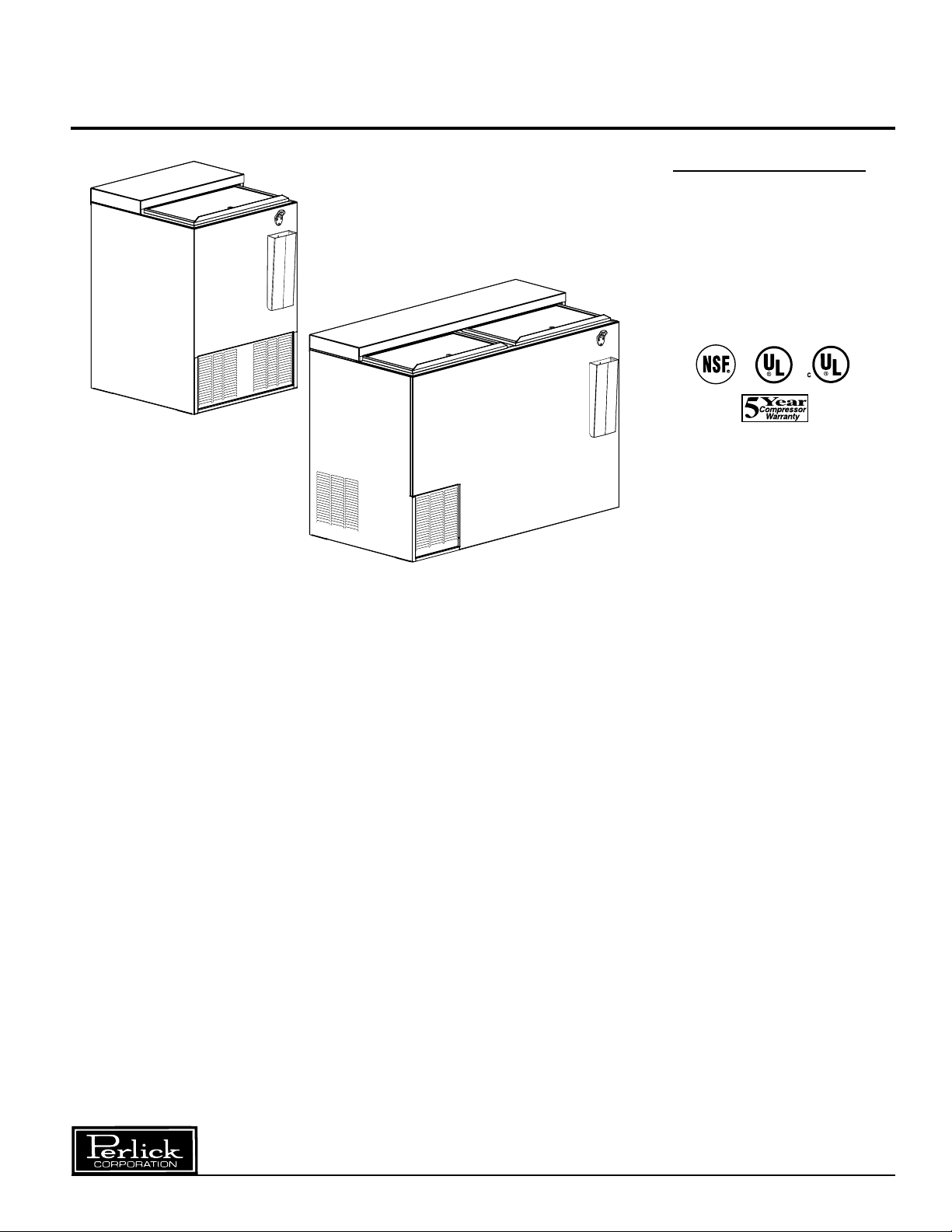
INSTALLATION AND OPERATION INSTRUCTIONS
FLAT TOP BOTTLE COOLER
MODEL NOS.
BC24 Series
BC36 Series
BC48 Series
BC60 Series
BC72 Series
BC96 Series
IMPORTANT INFORMATION
This manual has been prepared to assist you in the
installation of your Bottle Cooler and to acquaint you
with its operation and maintenance.
We dedicate considerable time to ensure that our
products provide the highest level of customer
satisfaction. If service is required, call Perlick at
1-800-777-7267 or your dealer who can provide you
with a list of qualified service agents. For your own
protection, never return merchandise for credit without our approval.
We thank you for selecting a Perlick product and
assure you of our continuing interest in your
satisfaction.
IMPORTANT WARRANTY INFORMATION
A Warranty card is enclosed that must be completed
and mailed to the Perlick Corporation to register the
warranty. If the card is not returned to Perlick, the
warranty period will begin from the date the
equipment is shipped from the factory.
Table of Contents
Cabinet Specifications ..........................................2
Installing
Uncrating and Inspection................................3
Plumbing.........................................................3
Electrical..........................................................3
Adjusting Partitions .........................................3
Installing Casters and Legs.............................3
Placing the Cabinet.........................................3
Sealing to the Floor .........................................3
Temperature Control .............................................4
Cleaning the Cabinet ............................................4
Wiring Diagram.....................................................5
Replacement Parts ............................................6/7
8300 West Good Hope Road • Milwaukee, WI 53223 • Phone 414-353-7060 • Fax 414-353-7069
Toll Free 800-558-5592 • E-Mail: Perlick@Perlick.com • www.Perlick.com
Form No. Z2219
Rev. 4.15.06
Page 2
Installation and Operating Instructions
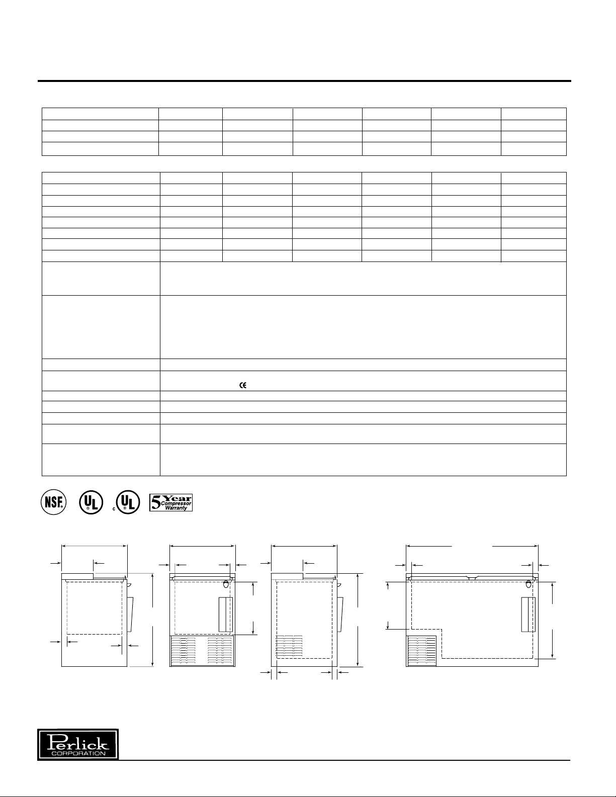
Sizes and Specifications, Flat Top Bottle Coolers
MODEL NUMBERS
BLACK BC24PG BC36PG BC48PG BC60PG BC72PG BC96PG
STAINLESS EXTERIOR BC24SG BC36SG BC48SG BC60SG BC72SG BC96SG
STAINLESS INTERIOR BC24SS BC36SS BC48SS BC60SS BC72SS BC96SS
ALL STAINLESS BC24AS BC36AS BC48AS BC60AS BC72AS BC96AS
SPECIFICA TIONS
LENGTH (mm) 24” (610) 36” (915) 48” (1219) 60” (1524) 72” (1828) 96” (2438)
INTERIOR CU. FT. (m3) 3.75 (0.10) 7.83 (0.22) 11.68 (0.33) 15.53 (0.44) 19.38 (0.55) 27.08 (0.77)
CASE CAPACITY(12oz. bottles) 5.5 9.75 17.2 21 28.3 41
CASE CAPACITY(12oz. cans) 7 16 25 30 36 58
NUMBER OF BINS 2 2 3 4 5 7
CONDENSING UNIT H.P.
AMPS 3.2 3.0 5.2 7.0 6.9 7.6
SHIP WT lbs. (kg) 190 (86) 245 (111) 300 (136) 353 (160) 405 (184) 515 (235)
INTERIOR Black and Stainless Exterior Models (PG & SG): Walls are galvanized steel. Floors are stainless steel.
EXTERIOR Black Model: Front and ends are 20 gauge, black vinyl coated steel. Back is galvanized steel.
DOORS (Sliding) Stainless steel top and door pan with ABS plastic frame and integral handle. Includes door locks.
ELECTRICAL 115V, 60 Hz., 1 Phase. Furnished with 6 foot rubber plug-in cord (115V model only). Also available in 230V, 50Hz.,
PLUMBING No drain required. Condensate evaporates automatically.
INSULATION 2 inch foamed-in-place polyurethane insulation.
REFRIGERATION R134a capillary tube/type with hermetic condensing unit. Pulls out for service and cleaning.
VENTILATION 2’ model is front vented, all other models require 2” clearance from wall on either left end or back of cabinet
OPTIONALACCESSORIES • Floor racks • Casters • Additional opener and receiver
1
⁄5
1
⁄5
1
⁄4
1
⁄3
1
⁄3
1
Stainless Interior and All Stainless Models (SS & AS): Walls and floor are stainless steel.
All Models: Adjustable vinyl coated wire partitions.
Bottom is galvanized steel.
Stainless Exterior and Stainless Interior Models: Front and ends are stainless steel. Back is galvanized steel.
Bottom is galvanized steel.
All Stainless Models: Front, ends, back and bottom are stainless steel.
All Models: Top is stainless steel. Aluminum front and back grilles and stainless steel cap receivers.
1 Phase AC. Carries marking of conformity.
for proper air flow.
• Additional partitions • Bottle rails
• Interior light kit • Adjustable legs
⁄3
2”
[50]
24”
[610]
11 5/8”
[295]
2”
[50]
END VIEW
24” CABINET
36” [914]
24”
[610]
2”
[50]
34 1/4”
[870]
FRONT VIEW
24” CABINET
Perlick is committed to continuous improvement. Therefore, we reserve the right to change specifications without prior notice.
2”
[50]
19 1/16”
[485]
INSIDE
2”
[50]
36”, 48”, 60”, 72” & 96”
24”
[610]
11 5/8”
[295]
END VIEW
CABINETS
34 1/4”
[870]
2”
[50]
2”
[50]
17 3/16”
[437]
HOUSING
STEP
48” [1219]
60” [1524]
72” [1829]
96” [2436]
FRONT VIEW
36”, 48”, 60”, 72” & 96”
CABINETS
2
2”
[50]
27 7/8”
[708]
INSIDE
Form No. Z2219
Rev. 4.15.06
Page 3

Preparing the Cabinet – Flat Top Bottle Coolers
Uncrating and Inspection
Remove all crating material before operating.
Carefully inspect cabinet for hidden damage.
If damage is discovered, file your claim immediately
with the transport company. Perlick is not
responsible for damage in transit.
Plumbing
No plumbing connections are required. Condensate
from the cooling coil automatically evaporated
through a condensate pan located in the
condensing unit section.
Electrical
The cabinet must be connected to a separately
fused power source (see Electrical Specification
Plate) and grounded in accordance with National
and Local Electrical Codes.
CAUTION: Do not attempt to operate the equipment
on any other power source than that listed on the
Electrical Specification Plate.
Placing the Cabinet
To assure maximum performance, fresh air must
be allowed to circulate through the machinery
compartment. It is important to allow at least two
inches of clearance at the back or left end of the
cabinet. Do not place anything in front of the
cabinet that would obstruct air flow at these grilles.
Do not place the unit in an unventilated small room.
CAUTION:
Removing the factory installed back clearance
spacers without providing proper left side grill
clearance for compressor air flow will void
the warranty.
Cabinet should be leveled.
For sanitation purposes, it may be necessary to
seal the base of the cabinet to the floor. This
can be accomplished by laying a bead of silicone
sealant along the base of the cabinet as shown
by the figure below.
Adjustable Partitions
Perlick Bottle Coolers are provided with adjustable
partitions which will accommodate various bottle
sizes.
■ Remove bottles and cans from their cases
before placing in cooler to ensure proper
air flow.
■ On 2’ and 3’ models keep air intake open for
proper circulation.
Installing Casters or Legs (optional)
Attach casters or legs to the cabinet bottom in holes
provided. Use the supplied
tapping machine screws. If unit is tipped on its back
for an extended period of time, wait 24 hours after
unit is uprighted to plug the unit in.
1
⁄4”–20 hex head self-
CABINET
BEAD SILICON
SEALER (RTV)
FLOOR
Perlick is committed to continuous improvement. Therefore, we reserve the right to change specifications without prior notice.
3
Form No. Z2219
Rev. 4.15.06
Page 4

How To Operate – Flat Top Bottle Coolers
Temperature Control
An adjustable temperature control is located inside
the Bottle Cooler on the evaporator fan panel
assembly. It is factory set at “Normal” approximately
38° F. Make adjustments as shown to attain the
desired temperature.
NOTE: Atemperature setting that is too low will not
allow enough condensing unit “off” time to maintain
a frost-free coil.
Colder Temperatures: Turn the adjusting
■
screw clockwise (to the right).
■ Warmer Temperatures: Turn the adjusting
screw counterclockwise (to the left).
■ Temperature Control “OFF”: Turn the
adjusting screw completely counterclockwise to the “O” position until a “click” is
noted.
The condenser fan motor turns off and on with
the compressor. The evaporator fan motor runs
continuously.
Cleaning the Condenser:
■ The condenser (located behind the front
grille) should be inspected every 30 days,
and cleaned, if necessary. Failure to keep
the condenser clean will cause a loss in
condensing unit efficiency, or compressor
failure.
Cleaning the Doors:
■ Doors should be periodically removed from the
cabinet and inspected for a buildup of foreign
materials, such as syrups, beer, etc. Buildups
on the underside of the doors, along with the
cabinet breaker strips on which they ride, will
cause them to bind, and therefore, not function
as designed. If dirty, these surfaces should be
cleaned with a mild detergent and water and
then coated with a silicone lubricating material.
Aerosol silicone sprays can be obtained locally
at most department or automotive stores.
To remove doors:
■ With door closed, lift it upward by its handle and
slide forward until door clears the cabinet top.
Use the reverse procedure to reinstall the doors.
Cleaning the Cabinet:
■ Use a damp cloth with a mild detergent and
water to clean the inside and outside of the
cabinet. Dry thoroughly. Do not allow cleaning
agents or large amounts of water to go down
the drain. Use an acceptable stainless steel
polish to clean all stainless steel surfaces.
Never use steel wool or scouring pads to clean
stainless steel.
Avoiding Stainless Steel Corrosion
Corrosion can be prevented by following product cautions, cleaning instructions and avoiding use of certain
chemicals or objects which will cause stainless steel corrosion.
STAINLESS STEEL ENEMY
■ Steel wool or steel scouring pads
■ Cherry/Orange/Olive juice
■ Chlorine Bleach
■ Sharp Objects
Perlick is committed to continuous improvement. Therefore, we reserve the right to change specifications without prior notice.
4
Form No. Z2219
Rev. 4.15.06
Page 5

Wiring Diagram – Flat Top Bottle Coolers
GREEN
TO CONDENSING UNIT
WHITE
BLACK
PLUG-IN-CORD
WHITE
EVAP.
FAN
EVAP.
FAN
2ND FAN ON
4’ THR U 8’ MODELS
BLACK
RED
TEMPERATURE
CONTROL
INSIDE OF
CONDENSING
UNIT HOUSING
Perlick is committed to continuous improvement. Therefore, we reserve the right to change specifications without prior notice.
INSIDE OF
CABINET
5
Form No. Z2219
Rev. 4.15.06
Page 6
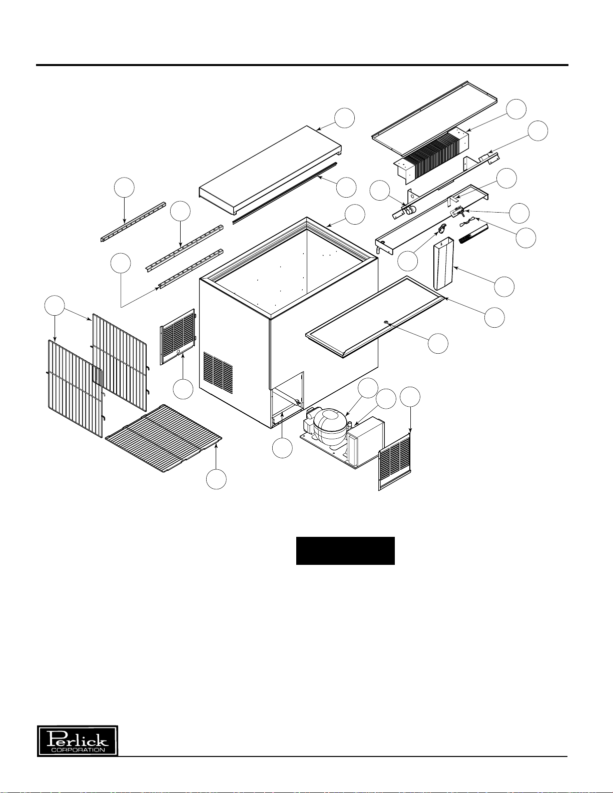
Replacement Parts – Flat Top Bottle Coolers
20
18
19
17
10
23
14
7
9
5A
8
4
21
13
1
11
2
5
6
22
12
15
3
CAUTION
■ Service should be done by a qualified
refrigeration technician.
■ Disconnect all power before servicing
the cabinet.
Perlick is committed to continuous improvement. Therefore, we reserve the right to change specifications without prior notice.
6
Form No. Z2219
Rev. 4.15.06
Page 7

Replacement Parts – Flat Top Bottle Coolers
MODEL NOS. BC24 BC36 BC48 BC60 BC72 BC96
Item Description Part Numbers
Complete condensing unit C22648 C22648 C22647 C22646 C22646 C22646
1 Replacement compressor R134a 513307046 513307046 513200314 513200003 513200003 513200003
2 Condensing unit fan motor assy. 215315009 215315009 215315009 215315009 215315009 215315009
Terminal board 219101538 219101538 219101538 219101538 219101538 219101538
Overload protector 4TM762NFBZZ-53 MRT20AGK5590 MRT22AFZ5590
Relay 213514067 213514067 213516191 213516051 213516051 213516051
Start capacitor (282-339MFD) N/A N/A 13556529 N/A N/A N/A
Start capacitor (378-454MFD) N/A N/A N/A 13556539 13556539 13556539
3 Condensate pan 64537 64626-1 64626-1 64626-1 64626-1 64626-1
4 Breaker strip kit 63608-1 63608-2 63608-3 63608-4 63608-5 63608-6
5 Evaporator fan motor C15239A C15239A (2) C15239A (2) C15239A (2) C15239A (2) C15239A
5A Evaporator fan motor bracket 65060-1 65060-1 (2) 60988-1 (2) 60988-1 (2) 60988-1 (2) 60988-1
6 Evaporator fan blade 63461 63461 (2) 57699 (2) 57699 (2) 57699 (2) 57699
7 Evaporator coil 64785-1EP C17511-1EP C17511-1EP C17511-2EP C17511-2EP C17511-2EP
8 Light bulb (when supplied) C15046 C15046 C15046 C15046 C15046 C15046
9 Temperature control 61283 61283 61283 61283 61283 61283
10 Back grille N/A 64644-1 64644-1 64644-1 64644-1 64644-1
11 Front grille 64167A-1 64643-1 64643-1 64643-1 64643-1 64643-1
12 Door assembly 66397-24L 66397-36L (2) 66397-24L 66397-24L (2) 66397-36L (2) 66397-36L
Door assembly (multiple doors) N/A N/A N/A 66397-36L N/A 66397-24L
13 Door Lock 63564 63564 63564 63564 63564 63564
14 Top wiper gasket 63671-24 63671-36 63671-48 63671-60 63671-72 63671-96
15 Bottom floor rack (wide) 64814-1 64814-1 64814-1 64814-1 64814-1 64814-1
16 Bottom floor rack (narrow) 64815-1 64815-1 64815-1 64815-1 64815-1 64815-1
17 Top front rail N/A 65013-36 65013-48 65013-60 65013-72 65013-96
18 Bottom front rail 65017-24 65017-36 65017-48 65017-60 65017-72 65017-96
19 Back rail 65016-24 65016-36 65016-48 65016-60 65016-72 65016-96
20 Divider rack 64813-1 (2) 64719-1 (2) 64719-1 (3) 64719-1 (4) 64719-1 (6) 64719-1
21 Bottle cap opener C6713-1 C6713-1 C6713-1 C6713-1 C6713-1 (2) C6713-1
22 Bottle cap holder C17332 C17332 C17332 C17332 C17332 (2) C17332
22A Bottle cap holder screws (2) M00504-122 (2) M00504-122 (2) M00504-122 (2) M00504-122 (2) M00504-122 (4) M00504-122
22B Bottle cap holder spacers (2) C122-2 (2) C122-2 (2) C122-2 (2) C122-2 (2) C122-2 (4) C122-2
23 Back top assembly 64692-24A 64692-36A 64692-48A 64692-60A 64692-72A 64692-96A
Items Not Shown
Wire harness 65043-1 65043-1 65044-1 65044-1 65044-1 65044-1
Evaporator tube (1
Evaporator tube (4
Cap tube/suction line heat
exchanger with dryer
Mullion assembly — — 64823R 64823R 64823R (2) 64823R
Light kit (accessory only) 63536 63536 63536 63536 63536 63536
Refrigerant charge (oz. R134a) 6.0 8.5 9.0 9.0 9.0 9.0
1
⁄4” U. bend) 63553-1 63553-1 63553-1 63553-1 63553-1 63553-1
1
⁄8” U. bend) 63554-1 63554-1 63554-1 63554-1 63554-1 63554-1
65072 65072 65073 65075 65075 65075
Perlick is committed to continuous improvement. Therefore, we reserve the right to change specifications without prior notice.
7
Form No. Z2219
Rev. 4.15.06
Page 8

8300 West Good Hope Road • Milwaukee, WI 53223 • Phone 414-353-7060 • Fax 414-353-7069
Toll Free 800-558-5592 • E-Mail: Perlick@Perlick.com • www.Perlick.com
Perlick is committed to continuous improvement. Therefore, we reserve the right to change specifications without prior notice.
Form No. Z2219
Rev. 4.15.06
 Loading...