

Page 1
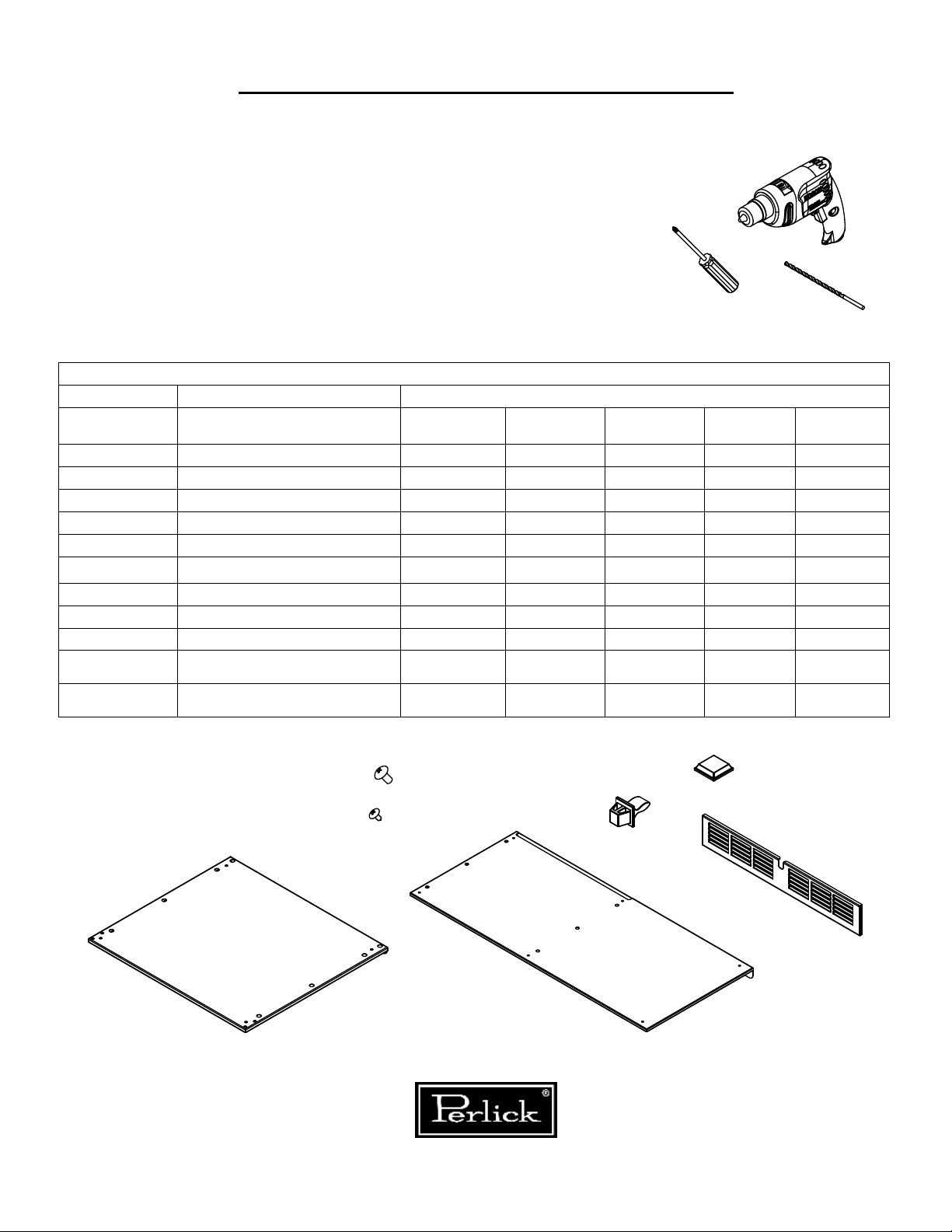
STACKING KIT INSTALLATION
IMPORTANT
For built-in applications only!
Tools Required
Drill
Ensure the anti-tip brackets are installed
per the installation and operating
manual that came with the cabinet.
Never install if used with caster kits or
extended leg kits.
Parts Required
Part Number Description HP15
63965 LATCH STRIKE 2 2 2 4 6
65700-2 15" Grille 1
65733-4 24" Grille 1 1 2 3
68094-15 15" Mounting Plate 1
68094-24 24" Mounting Plate 1
68094-24x18 24"x18" Mounting Plate 1
68094-48 48" Mounting Plate 1
68094-72 72" Mounting Plate 1
C31323 Bumper, Adhesive Poly 4 4 4 8 12
M00885-189
M50050-466
1/4-20 X 1/2" MACHINE
SCREW
#10 X 1/2" SHEET METAL
SCREW
4 4 4 6 6
2 2 2 5 5
HP24 &
HC24
Phillips
Screwdriver
MODEL
HH24 &
HA24-18
5/32" Drill Bit
HP48 HP72
1/4-20 X 1/2" MACHINE SCREW
#10 X 1/2" SHEET METAL SCREW
15" & 24" Mounting Plate
8300 W. Good Hope Rd. Milwaukee, WI 53223 Phone: (414)353-7060 Fax: (414)-353-7069 perlick.com
Perlick is comitted to continuous improvement. Therefore, we reserve the right to change specifications without warning
BUMPER, ADHESIVE POLY
LATCH STRIKE
48" & 72" Mounting Plate
-1-
Grille
95010 REV C
Page 2

STACKING KIT INSTALLATION
These cabinets are extremely heavy. Ensure that you have
enough people on hand to help in repositioning of the unitsCAUTION:
so that it can be done safely and without damage.
Step 1: Drill out top row of rivets along back of the bottom cabinet
using 5/32" drill bit.
2 rivets on 24 and 15
inch wide cabinets.
Back View
5 rivets on 48 and 72
inch wide cabinets.
Back View
Step 2: Lay upper cabinet on its back and remove leg levelers and
grille(s) from unit.
Remove 2 additional
leg levelers from
Remove 4 leg
levelers from all
sizes of upper units.
8300 W. Good Hope Rd. Milwaukee, WI 53223 Phone: (414)353-7060 Fax: (414)-353-7069 perlick.com
Perlick is comitted to continuous improvement. Therefore, we reserve the right to change specifications without warning
48 and 72 units.
-2-
95010 REV C
Page 3

STACKING KIT INSTALLATION
Step 3: Attach mounting plate (where the leg levelers were removed
in step 2) by using 1/4-20 machine screws . Flange should be
pointing away from the bottom of the unit.
Bottom of
cabinet
Flange
Step 4: Place upper unit on top of lower unit and attach using #10
sheet metal screws (where the rivets were drilled out in step 1).
7
68
"
8
NOTE: EXTENSION OF LEG LEVELERS
WILL INCREASE ASSEMBLY HEIGHT
8300 W. Good Hope Rd. Milwaukee, WI 53223 Phone: (414)353-7060 Fax: (414)-353-7069 perlick.com
Perlick is comitted to continuous improvement. Therefore, we reserve the right to change specifications without warning
-3-
95010 REV C
Page 4

STACKING KIT INSTALLATION
Step 5: Attach -4- bumpers and -2- latch strikes to each new grille.
Orient tabs vertically. Attach grille assemby to upper unit.
Move stacked assembly into final position by pushing lower unit.
This edge
vertical.
Bumper
Note:When using stacking kit to join -2- HH24
or HC24-18 units, a wall mount anti-tip kit
must be installed. See cabinet manual
for instructions.
8300 W. Good Hope Rd. Milwaukee, WI 53223 Phone: (414)353-7060 Fax: (414)-353-7069 perlick.com
Perlick is comitted to continuous improvement. Therefore, we reserve the right to change specifications without warning
-4-
95010 REV C
 Loading...