

Ultraviolet System
OWNER’S GUIDE
Contents
How Your Ultraviolet Air Treatment System or Surface Treatment System Works ..................................................................... 2
Be Sure to Read Warnings and Cautions Before Installing or Using Your UV System ............................................................... 3
How to Install Your Ultraviolet System ......................................................................................................................................... 4
How You Can Check Your Ultraviolet System ............................................................................................................................. 7
How You Can Maintain Your UV System ..................................................................................................................................... 7
69-1859EFS-01
ULTRAVIOLET SYSTEM
IMPORTANT
Please read these instructions and keep them in your records.
HOW YOUR ULTRAVIOLET AIR TREATMENT SYSTEM OR SURFACE TREATMENT SYSTEM WORKS
Depending on installation, your Ultraviolet System can operate as an Air Treatment System or as a Surface Treatment System.
Air Treatment System
Installed in the return air duct of your system, your Ultraviolet
Air Treatment System kills a high percentage of airborne
germs circulating through your forced air heating and cooling
!
W
A
R
N
IN
G
N
/A
o
V
c
i
E
fs
R
V
p
T
e
o
IS
u
u
ille
S
r
E
la
l’in
z
M
lire
p
E
s
e
ta
N
a
et b
u
l
T
la
n
t
io
u
i
e
e
n
n
e
e
t
c
t l
o
l
e
a
mp
s
m
re
a
i
n
n
d
te
r
e
n
a
n
c
e
.
system. Individual results depend on careful installation and
maintenance and on the actual amount of time your system
fan operates. See Fig. 1.
ENT
ISSEM
VERT
/A
s
le
t
NING
e
e
AR
u
n
re
W
!
u
a
rend
p
pe
a
l
.
om
r
e
c
u
c
o
n
n
ie
p
t b
ifs
c
e
ntena
i
o
a
N
lire
m
z
e
ill
et la
eu
n
V
tio
a
stall
l’in
M22858
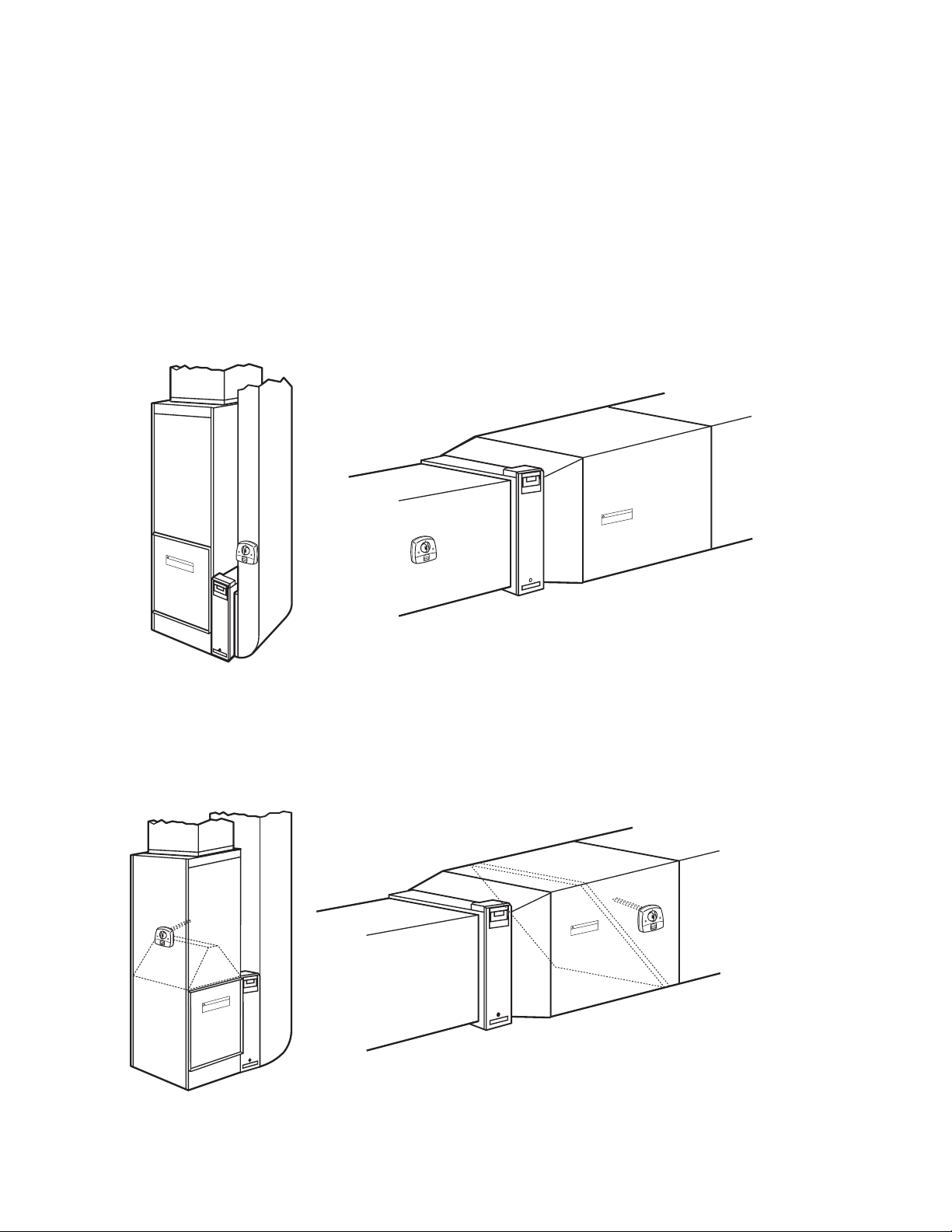
Fig. 1. Typical Air Treatment System installations.
Surface Treatment System
When installed next to the cooling coil of your system, your
Ultraviolet Surface Treatment System prevents a high
percentage of the growth of micro-organisms such as mold
NT
E
SSEM
TI
VER
s
A
e
/
l
G
et
e
e
r
u
d
n
n
ARNIN
u
e
r
a
W
p
e
!
.
m
p
e
a
c
co
l
n
r
a
n
u
n
ie
o
e
t
b
t
in
s p
e
a
if
c
e
m
r
o
i
l
N
la
z
t
e
l
e
il
n
u
o
e
i
t
V
lla
a
t
s
in
l’
Fig. 2. Typical surface treatment installations.
that may grow on duct surfaces, coils, and drain pans.
Individual results depend on careful installation and
maintenance. See Fig. 2.
T
EMEN
S
TIS
R
VE
/A
G
s
IN
le
t
e
e
ARN
u
re
W
n
d
!
u
n
a
e
e
r
p
p
a
m
l
.
o
r
e
u
c
c
o
n
e
i
p
nan
s
b
t
if
te
c
e
in
o
e
a
N
lir
z
t la m
ille
u
e
e
n
V
io
t
lla
ta
s
l’in
M22860
69-1859EFS—01 2
ULTRAVIOLET SYSTEM
You can capture and minimize micro-organisms passing
through your forced air system when you combine your UV
System with a high-efficiency air filtration system like an
electronic air cleaner. Talk to your local heating and cooling
contractor about adding an electronic air cleaner to
complement your UV System and provide added protection
for you and your family.
BE SURE TO READ WARNINGS AND CAUTIONS BEFORE INSTALLING OR USING YOUR UV SYSTEM
MERCURY NOTICE
This device contains mercury in the sealed ultraviolet
WARNING
UV Light Hazard.
Harmful to bare skin and eyes.
Can cause temporary or permanent loss of vision.
Never look at bulbs while illuminated.
View illumination only through light indicator located
on lamp handle.
To prevent exposure to ultraviolet light, disconnect
power to Ultraviolet System before servicing any part
of heating and air conditioning system.
Do not mount device in location that allows ultraviolet
light to be seen after installation.
Do not attempt to bypass duct mount switch.
Do not attempt to open housing; unit is sealed to
prevent ultraviolet light exposure.
bulb(s). Do not place your used bulb(s) in the trash.
Dispose of properly.
Broken Bulb Cleanup.
Do not use a household vacuum.
Sweep debris (phosphor/glass) into a plastic bag and
dispose of properly.
Contact your local waste management authority for
instructions regarding recycling and the proper
disposal of old bulb(s).
CAUTION
Equipment Damage Hazard.
CAUTION
Personal Injury Hazard.
Power supply can cause electrical shock.
Disconnect power supply before cleaning or replacing
ultraviolet bulb(s).
Do not open base unit or lamp handle; there are no
user-serviceable components inside.
Ultraviolet light can cause color shift or structural
degradation of plastic HVAC materials.
Select mounting location that prevents exposure to
plastic components with unknown resistance to
ultraviolet light. Three-feet minimum is recommended
between ultraviolet lamp and plastic-fabricated
devices (such as wires and non-fiberglass media
filters).
CAUTION
Breakable Glass Hazard.
Can cause personal injury.
Be careful when inserting bulb(s) into lamp base.
Wear protective gloves when handling bulb(s).
CAUTION
UV Lamp Burn Hazard.
Harmful to bare skin.
Can cause severe burns.
Disconnect power 15 minutes before removing the
ultraviolet bulb(s).
NOTE: Most drain pans and humidifiers are UV-C resistant.
Consult Honeywell’s UV exposure white paper, Form
No. 50-8788.
CAUTION
Sharp Edges Hazard.
Can cause personal injury.
Be careful when inserting ultraviolet device into the
sheet metal cutout.
Wear protective gloves when working near sheet
metal.
3 69-1859EFS—01
ULTRAVIOLET SYSTEM
HOW TO INSTALL YOUR ULTRAVIOLET SYSTEM
When Installing this Product…
1. Read these instructions carefully. Failure to follow them
could damage the product or cause a hazardous
condition.
2. After installation is complete, check out product opera-
tion as provided in these instructions.
Selecting Mounting Location
Depending on installation location, the UV System can
operate as an Air Treatment System or as a Surface
Treatment System.
1. The UV System can be mounted in any orientation.
2. Choose a location that is readily accessible for regular
inspection and cleaning.
3. The UV Air Treatment System requires an easily-acces-
sible, flat mounting surface on the metal return air duct
of the HVAC system. The UV Surface Treatment System requires an easily-accessible, flat mounting surface
on the metal supply air duct of the HVAC system. The
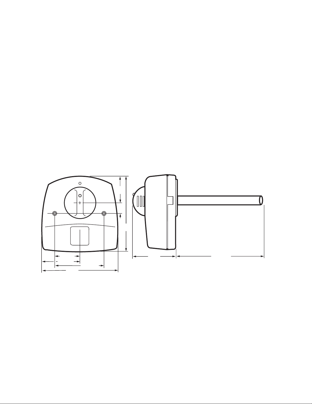
2-1/2
(64)
UV Surface Treatment System must be located so the
lamp surrounds the evaporator coil and drip pan with
ultraviolet light.
4. The duct mounting location must be a minimum of 8 in.
wide. See Fig. 3.
5. The depth of the duct must accommodate the full length
of the ultraviolet bulb as shown in Fig. 3.
6. The unit should be located as far away as possible from
any rubber or plastic components, such as isolators, in
the duct.
IMPORTANT
If mounting options are limited, protect plastic or rubber materials listed in CAUTION with ultravioletresistant material such as aluminum foil duct tape.
7. The space adjacent to the mounting location must be
large enough to allow for ultraviolet bulb installation and
removal.
8. A 120V electrical outlet must be within range of the unit
to plug in the power cord.
1
(25)
7
(178)
2-1/4 (57)
3-1/2 (89)
7 (178)
4-1/2 (114)
Fig. 3. Ultraviolet System dimensions in in. (mm).
Duct Mounting
Use the following instructions to mount the UV System on the
air duct of an HVAC system:
1. Disconnect power to the HVAC system before installing
the UV System.
4 (102)
7-7/16 (188)
M18990
2. Tape the template (Fig. 4) on the duct surface, centering
the bulb hole on the duct.
3. Cut the 2 in. bulb hole in the duct. See Fig 5. Remove
any burrs.
69-1859EFS—01 4
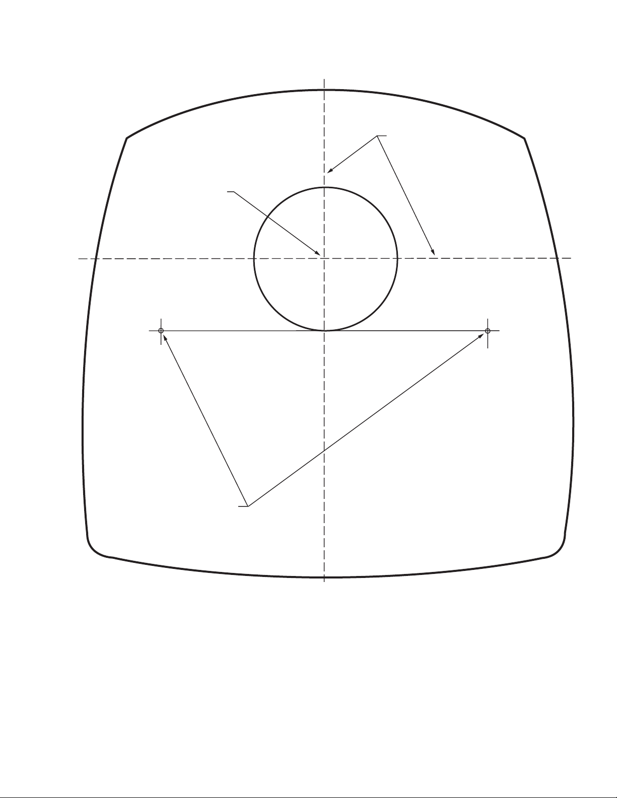
CENTER OF 2 IN. (51 MM)
HOLE FOR LAMP
ALIGN EITHER OF THESE LINES
AS CLOSE AS POSSIBLE TO
DUCT CENTER LINE
ULTRAVIOLET SYSTEM
3/32 IN. (3 MM) PILOT HOLES
FOR MOUNTING SCREWS
Fig. 4. Ultraviolet System template.
4. Use a 3/32 in. drill to provide pilot holes for the mounting
screws.
5. Be sure the duct surface is flat after all holes are drilled.
6. Position the entire base unit on the duct. Be sure the
bulb holes in the duct align with those in the unit to allow
bulb insertion.
M18991
7. Install the unit on to the duct using the two no.10, 2 in.
Phillips head sheet metal mounting screws provided.
8. Tighten the screws so the space between the case and
duct is sealed.
5 69-1859EFS—01
ULTRAVIOLET SYSTEM
C
E
N
T
E
R
O
F
2
I
N
.
(5
1
M
M
)
H
O
L
E
F
O
R
LA
M
P
3
/3
2
IN
.
(
3
M
M
) P
I
L
O
T
H
O
L
E
S
F
O
R
M
O
U
N
T
I
N
G
S
C
R
E
W
S
A
L
I
GN
E
I
T
H
E
R
O
F
T
H
E
S
E
L
I
N
E
S
A
S
C
L
O
S
E
A
S
P
O
S
S
I
B
L
E
TO
D
UCT
C
E
N
T
E
R
L
I
N
E
A
L
IG
N
E
I
T
H
E
R
O
F
A
T
S
H
E
C
S
L
O
E
S
L
E
IN
A
E
S
S
P
O
S
D
S
U
IB
C
L
T
E
C
TO
E
N
T
E
R
L
IN
E
C
E
N
T
E
R
O
F
2
I
N
.
(
51 M
M
)
H
O
L
E
F
O
R
L
A
M
P
3
/3
2
IN
.
(
3
M
M
) P
I
L
O
T
F
H
O
O
R
LE
M
O
U
N
T
IN
G
S
C
R
E
W
S
S
M13603
Fig. 8. Insert bulb into base unit.
M18989
Fig. 5. Cut the bulb hole in the duct.
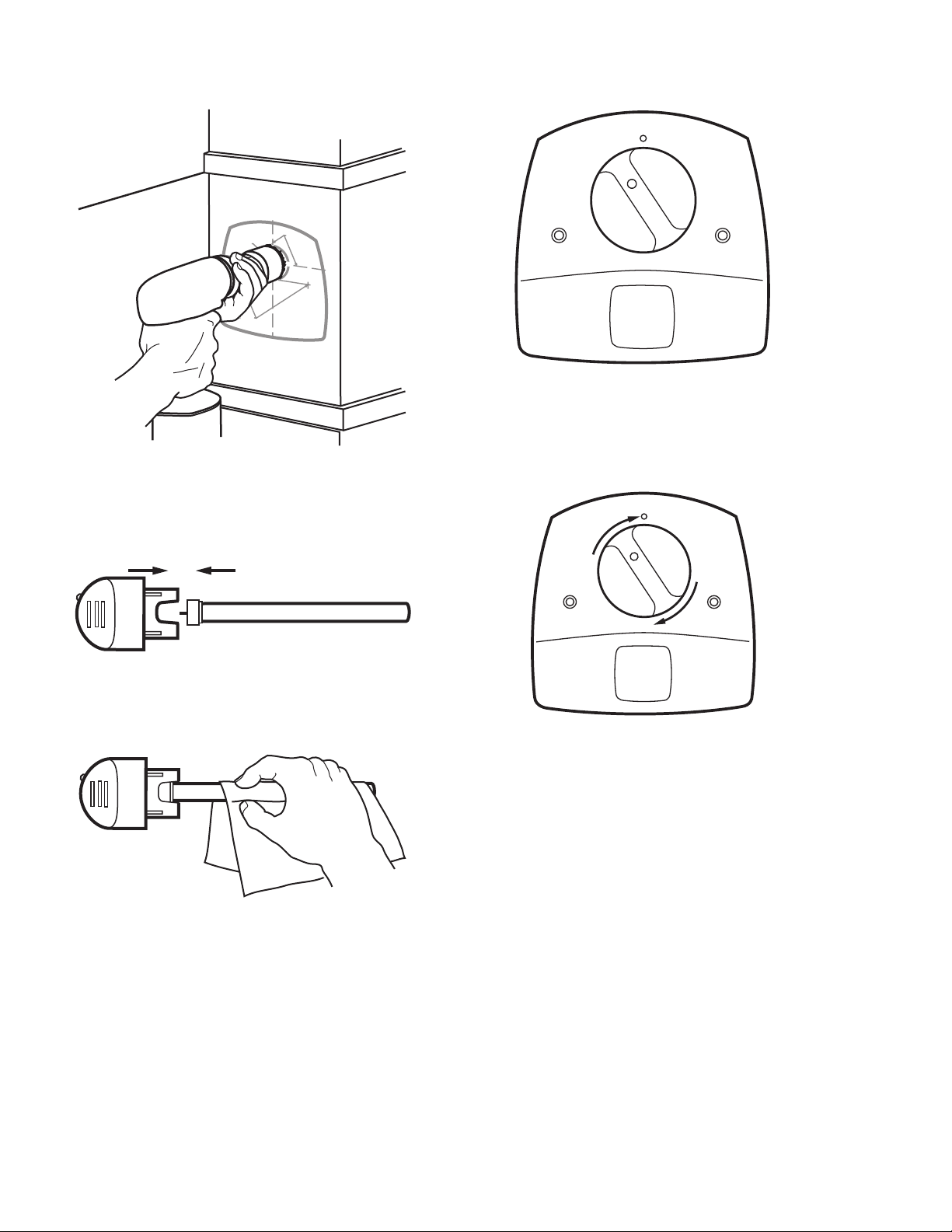
9. Insert the new lamp glass into the lamp handle by align-
ing the key and pushing straight together.
See Fig. 6.
M22854A
Fig. 6. Place lamp glass in lamp handle.
10. If you touch the lamp glass with your hands, use a cloth
to wipe fingerprints from the glass. See Fig. 7.
M22843
Fig. 7. Use cloth to wipe fingerprints from glass.
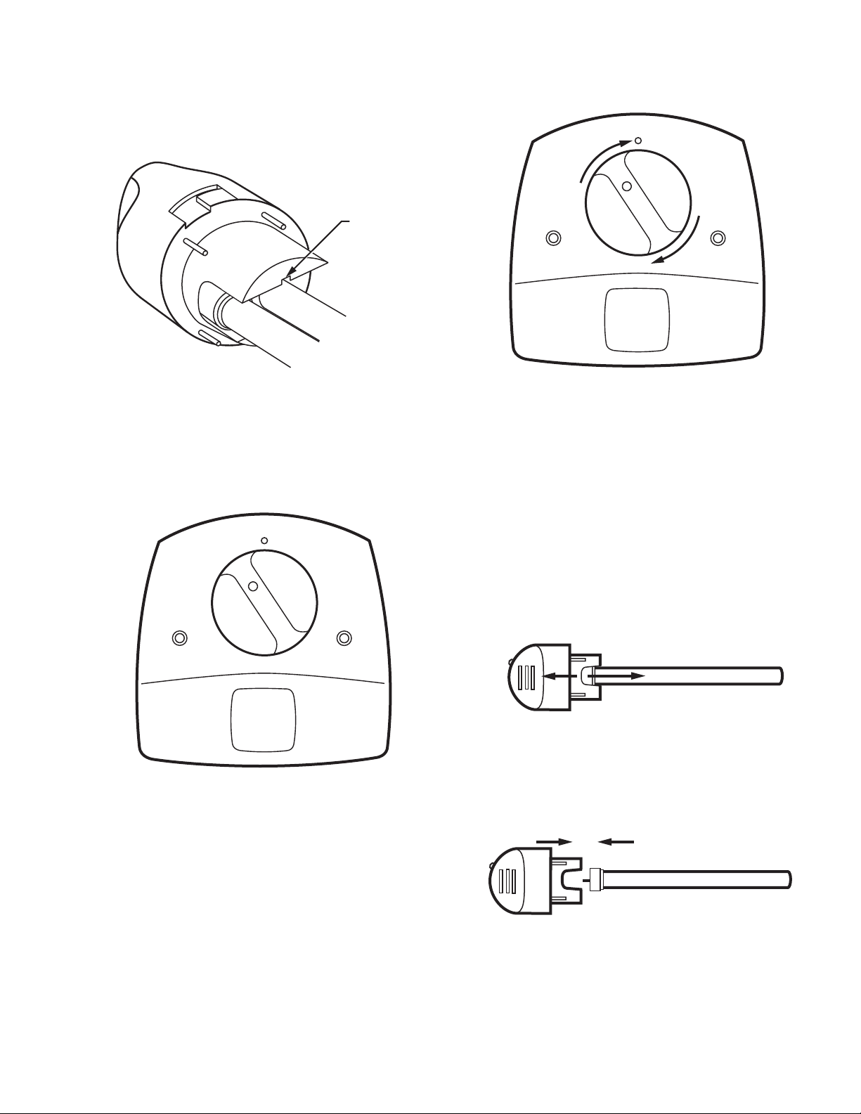
11. Insert the bulb into the base unit with the lamp light indi-
cator at the eleven o’clock position (left of the raised
button on the unit cover). See Fig. 8.
12. Continue lightly pushing in on the lamp handle while
rotating it slowly counterclockwise. This should cause
the lamp handle to drop into the bottom of the lamp well.
13. Rotate the lamp handle clockwise until it snaps into
place with the lamp indicator light aligned with the
raised button on the unit cover. See Fig. 9.
M13604
Fig. 9. Snap lamp into place.
14. Plug the cord into the nearby 120 Vac electrical outlet.
15. Reconnect the power to the HVAC system.
16. Choose a location on the adjacent HVAC equipment for
the HVAC maintenance label included in the air treatment system packing box. Choose a location that a
future service technician can easily see during any
future HVAC maintenance or repair.
17. Adhere the HVAC maintenance safety label to the
HVAC equipment (selected in step 16) such as the furnace access door, air cleaner or humidifier.
See Fig. 10.
69-1859EFS—01 6
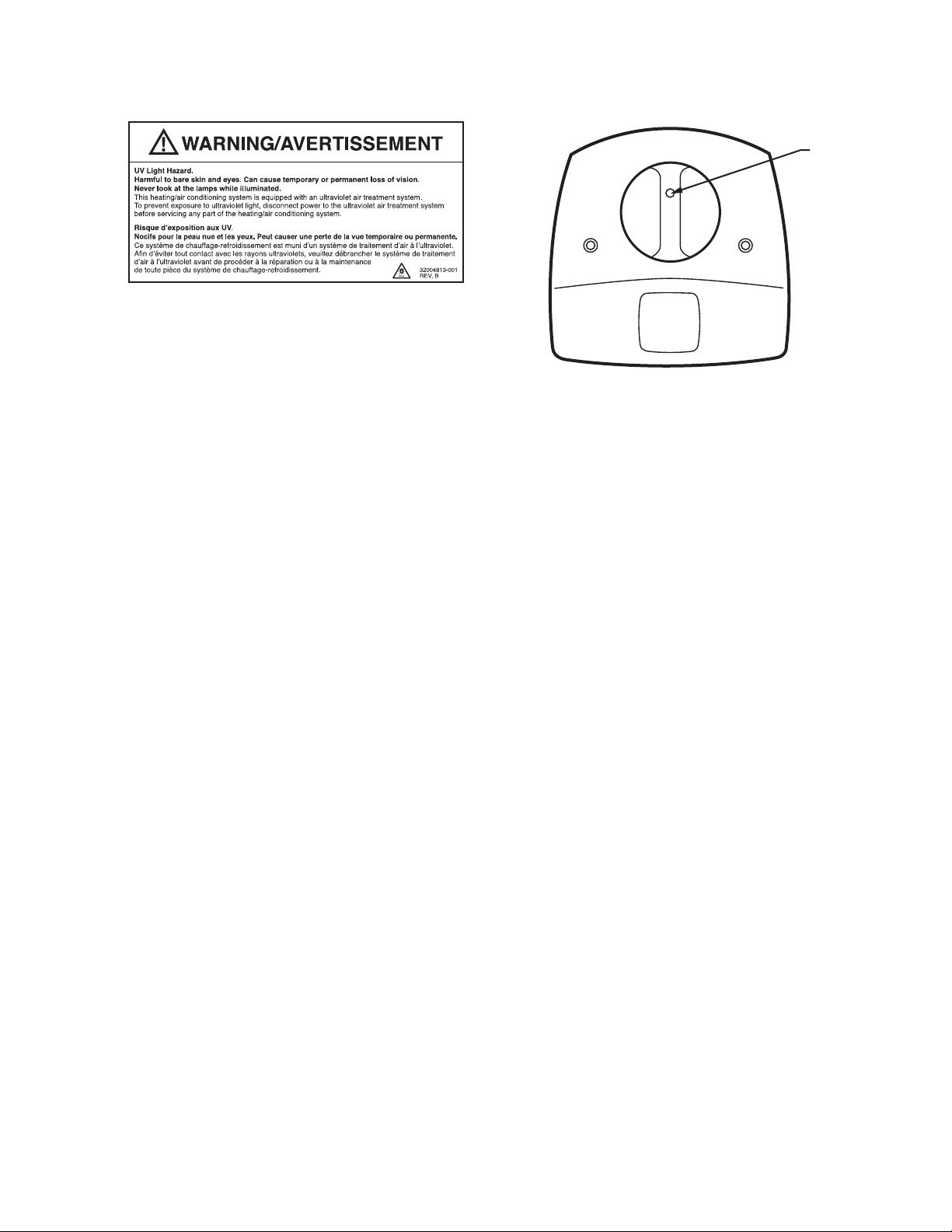
Fig. 10. HVAC maintenance UV safety label.
M22868
ULTRAVIOLET SYSTEM
LAMP
LIGHT
INDICATOR
HOW YOU CAN CHECK YOUR ULTRAVIOLET SYSTEM
Your UV System is designed to prevent accidental contact
with electrical voltage and with ultraviolet rays in the sealed
unit⎯the ultraviolet lamp does not illuminate unless the base
is mounted on your forced air system duct.
It is recommended that every month you verify that your
ultraviolet lamp is operating. View the bulb only through the
lamp light indicator on the lamp handle. See Fig. 11.
Do not attempt to look into the duct at the illuminated bulb(s).
M22840
Fig. 11. Lamp light indicator.
HOW YOU CAN MAINTAIN YOUR UV SYSTEM
You should regularly clean your UV System to maintain peak
effectiveness of your air treatment or surface treatment
system. Replace the ultraviolet bulb once a year.
Quarterly Bulb Cleaning
Bulb cleaning is recommended as routine maintenance four
times a year or every three months. Use the UV Bulb Cleaning
Reminder Schedule, Fig. 12, to help establish and track your
regular cleaning schedule.
To clean your bulb(s):
1. Disconnect the power to your heating and cooling sys-
tem.
2. Unplug or turn off power to your UV System and allow
the bulb(s) to cool for at least 15 minutes.
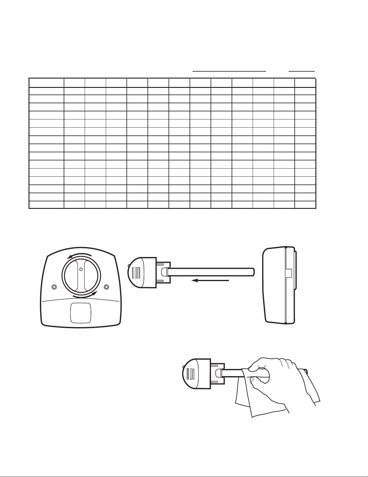
3. Rotate your lamp handle counterclockwise and gently
pull the lamp handle to remove the bulb. See Fig. 13.
7 69-1859EFS—01
ULTRAVIOLET SYSTEM
A
UV BULB CLEANING REMINDER SCHEDULE
YEAR
INSTALLATION DATE: (month)
, (year)
JFMAMJJASOND
M13516
Fig. 12. UV bulb cleaning reminder schedule.
Fig. 13. Remove lamp bulb.
4. Holding the lamp handle, wipe the lamp glass using a
soft cloth dampened with glass cleaner. If you touch the
lamp glass with your hands, be sure to clean the area of
any oils left from bare hands. See Fig. 14.
69-1859EFS—01 8
M22842
M22844
Fig. 14. Clean glass with soft cloth.
5. Also wipe away any dust that may have collected
between the lamp light indicator on the base and the
black bulb base. See Fig. 15.
LAMP LIGHT
INDICATOR
BASE
ULTRAVIOLET SYSTEM
M22846
Fig. 15. Wipe lamp light indicator base.
6. Dry bulb with a clean, dry cloth.
7. Insert the bulb into the base with the lamp light indicator
at the eleven o’clock position. Continue pushing and
gently rotating counterclockwise until the lamp handle
inserts fully into the base. See Fig. 16.
M13603
Fig. 16. Position bulb for insertion back into
the lamp base.
M13605
Fig. 17. Snap bulb into place.
Bulb Replacement
Annual replacement of the bulb in your ultraviolet lamp is
required to maintain effectiveness.
1. Obtain the replacement bulb (Part No. RUVBULB1) for
your unit from your retailer.
2. Disconnect the power to your heating and cooling sys-
tem.
3. Unplug or turn off power to your UV System and allow
lamps to cool for at least 15 minutes.
4. Rotate the lamp handle counterclockwise and gently
pull the lamp handle to remove the bulb. See Fig. 13.
5. Grasp the lamp handle in one hand and the lamp glass
in the other and pull straight apart. See Fig. 18.
M22852
Fig. 18. Disconnect lamp glass from lamp handle.
6. Insert the new lamp glass into the lamp handle by align-
ing the key and pushing straight together.
See Fig. 19.
8. Rotate the lamp handle clockwise until it snaps into
place with the lamp light indicator aligned with the
raised button on the unit cover. See Fig. 17.
9. Reconnect power to your UV System.
10. Verify that your ultraviolet bulbs are operating by view-
ing only through the lamp light indicator on the lamp
handle. Never look directly at your bulb while it is illuminated.
11. Reconnect power to your heating and cooling system.
M22854A
Fig. 19. Replace lamp glass in lamp handle.
7. If you touch the lamp glass with your hands, use a cloth
to wipe fingerprints from the glass. See Fig. 7
9 69-1859EFS—01

ULTRAVIOLET SYSTEM
8. Insert the bulb into the base with the lamp light indicator
at the eleven o’clock position. Continue pushing and
gently rotating counterclockwise until the lamp handle
inserts fully into the base. See Fig 16.
9. Rotate the lamp clockwise until it snaps into place with
the lamp light indicator aligned with the raised button on
the unit cover. See Fig. 17.
10. Reconnect power to your UV System.
11. Verify that your ultraviolet bulb is operating by viewing
only through the lamp light indicator on the lamp handle.
Never look directly at your bulb while it is illuminated.
12. Reconnect power to your heating and cooling system.
69-1859EFS—01 10

ULTRAVIOLET SYSTEM
Limited Warranty
Honeywell warrants this product, excluding bulbs, to be free from defects in the workmanship or materials, under normal use and service, for a
period of one (1) year from the date of purchase by the consumer. If, at any time during the warranty period, the product is defective or
malfunctions, Honeywell shall repair or replace it (at Honeywell’s option) within a reasonable period of time.
If the product is defective, return it, with a bill of sale or other dated proof of purchase, to the retailer from which you purchased it.
This warranty does not cover removal or reinstallation costs. This warranty shall not apply if it is shown by Honeywell that the defect or
malfunction was caused by damage which occurred while the product was in the possession of a consumer.
Honeywell’s sole responsibility shall be to repair or replace the product within the terms stated above. HONEYWELL SHALL NOT BE LIABLE
FOR ANY LOSS OR DAMAGE OF ANY KIND, INCLUDING ANY INCIDENTAL OR CONSEQUENTIAL DAMAGES RESULTING, DIRECTLY OR
INDIRECTLY, FROM ANY BREACH OF ANY WARRANTY, EXPRESS OR IMPLIED, OR ANY OTHER FAILURE OF THIS PRODUCT. Some
states do not allow the exclusion or limitation of incidental or consequential damages, so this limitation may not apply to you.
THIS WARRANTY IS THE ONLY EXPRESS WARRANTY HONEYWELL MAKES ON THIS PRODUCT. THE DURATION OF ANY IMPLIED
WARRANTIES, INCLUDING THE WARRANTIES OF MERCHANTABILITY AND FITNESS FOR A PARTICULAR PURPOSE, IS HEREBY
LIMITED TO THE ONE YEAR DURATION OF THIS WARRANTY. Some states do not allow limitations on how long an implied warranty lasts, so
the above limitation may not apply to you.
This warranty gives you specific legal rights, and you may have other rights which vary from state to state.
If you have any questions concerning this warranty, please write Honeywell Customer Relations, 1985 Douglas Dr. N MN10-1461, Golden Valley,
MN 55422 or call 1-800-468-1502, Monday-Friday, 7:00 a.m. to 5:30 p.m., Central time. In Canada, write Honeywell Limited/Honeywell Limitée,
35 Dynamic Dr., ON15, Toronto, Ontario M1V4Z.
11 69-1859EFS—01

ULTRAVIOLET SYSTEM
Automation and Control Solutions
Honeywell International Inc. Honeywell Limited-Honeywell Limitée
1985 Douglas Drive North 35 Dynamic Drive
Golden Valley, MN 55422 Toronto, Ontario M1V 4Z9
customer.honeywell.com
® U.S. Registered Trademark
© 2007 Honeywell International Inc.
69-1859EFS—01 M.S. Rev. 07-07
M18621B

Système à rayons ultraviolets
MODE D'EMPLOI
Table des matières
Comment fonctionne votre système de traitement d'air ou de surfaces aux rayons ultraviolets ................................................. 14
À lire sans faute : avertsissement et mises en garde à respecter avant d'installer votre système UV ........................................ 15
Comment installer le système à rayons ultraviolets .................................................................................................................... 16
Comment vérifier le système à rayons ultraviolets ...................................................................................................................... 19
Comment entretenir le système à rayons ultraviolets ................................................................................................................. 19

SYSTÈME À RAYONS ULTRAVIOLETS
IMPORTANT
Veuillez lire le présent mode d'emploi et le conserver.
COMMENT FONCTIONNE VOTRE SYSTÈME DE TRAITEMENT D'AIR OU DE SURFACES AUX RAYONS ULTRAVIOLETS
Selon l'installation, le système à rayons ultraviolets peut servir de traitement d'air ou de système de traitement de surfaces.
Système de traitement d'air
S'il est installé dans la gaine de reprise d'air de votre système,
le système de traitement à rayons ultraviolets élimine un
grand pourcentage des microbes contenus dans l'air qui
circule à travers le système de chauffage et de
refroidissement à air pulsé. Les résultats obtenus par votre
système en particulier reposent sur une installation adéquate
et un bon entretien, ainsi que sur la durée réelle de
fonctionnement du ventilateur du système. Voir la Fig. 1.
ENT
ISSEM
VERT
/A
s
le
t
NING
e
e
AR
u
n
re
W
d
!
u
a
ren
p
pe
a
m
l
.
o
r
e
u
c
o
n
nc
a
p
s
t bie
if
ten
c
e
n
i
o
a
N
lire
m
ez
ill
u
e
n et la
V
atio
stall
l’in
!
W
A
R
N
IN
G
N
/A
o
V
c
i
E
f
s
R
V
p
T
e
o
IS
u
u
ille
S
r
l
E
l’in
a
z
M
lire
p
E
s
e
ta
N
a
u
e
l
T
la
t b
n
t
io
u
i
e
e
n
n
e
e
t
c
t l
l
o
e
a
mp
s
m
re
a
i
n
n
d
te
r
e
n
a
n
c
e
.
Fig. 1. Installations types du système de traitement d'air.
Système de traitement de surfaces
Lorsqu'il est installé à proximité du serpentin de
refroidissement, le système de traitement à rayons ultraviolets
empêche la croissance d'un grand pourcentage de microorganismes tels que les moisissures qui croissent parfois sur
M22858
la surface des serpentins et des bacs à condensats. Les
résultats obtenus par votre système en particulier reposent sur
une installation adéquate et un bon entretien. Voir la Fig. 2.
T
EMEN
RTISS
VE
/A
G
s
IN
le
t
N
e
R
e
A
u
re
W
n
d
!
u
n
a
e
e
r
p
p
a
m
l
.
o
r
e
u
c
c
o
n
e
i
p
nan
s
b
t
if
te
c
e
in
o
e
a
N
lir
z
t la m
ille
u
e
e
n
V
io
t
lla
ta
s
l’in
NT
E
SSEM
TI
VER
s
A
e
l
G/
et
e
e
r
u
d
n
n
ARNIN
u
e
r
a
W
p
e
!
.
m
p
e
a
c
l
co
n
r
a
n
u
n
ie
o
e
t
b
t
in
s p
f
e
a
i
c
e
m
o
ir
l
N
la
z
t
e
l
e
l
i
n
u
o
e
i
t
V
lla
a
t
s
n
’i
l
Fig. 2. Installations types de système de traitement de surfaces.
69-1859EFS—01 14
M22860

SYSTÈME À RAYONS ULTRAVIOLETS
Il est possible de réduire au minimum la présence de microorganismes dans votre système à air pulsé en combinant le
système de traitement à rayons ultraviolets à un système de
filtration à haute efficacité, tel qu'un filtre à air électronique.
Informez-vous auprès de votre entrepreneur local en
chauffage-refroidissement de la possibilité d'ajouter un filtre à
air électronique à votre système de traitement à rayons
ultraviolets afin d'offrir une protection accrue à votre famille
comme à vous-même.
À LIRE SANS FAUTE : AVERTSISSEMENT ET MISES EN GARDE À RESPECTER AVANT D'INSTALLER VOTRE SYSTÈME UV
AVIS SUR LE MERCURE
Cet appareil contient du mercure scellé dans une
AVERTISSEMENT
Danger : lampe UV.
Les rayons sont nocifs pour la peau et les yeux.
Ils peuvent provoquer la perte temporaire ou
permanente de la vue.
Ne jamais regarder l'ampoule lorsqu'elle est allumée.
L'indicateur de la lampe, situé sur la poignée, sert à
vérifier si l'ampoule est allumée.
Pour éviter l'exposition aux rayons ultraviolets, couper
l'alimentation au système UV avant de procéder à
l'entretien de toute pièce du système de chauffage et
conditionnement d'air.
Ne pas installer l'appareil dans un endroit où la lampe
UV peut être visible une fois l'installation terminée.
Ne pas tenter de contourner l'interrupteur monté sur la
gaine.
Ne pas tenter d'ouvrir le boîtier : l'appareil est scellé
pour éviter toute exposition aux rayons ultraviolets.
MISE EN GARDE
Risque de blessure.
Peut provoquer des chocs électriques.
Couper l'alimentation électrique avant de procéder à
l'entretien ou de remplacer l'ampoule ou les ampoules
à rayons ultraviolets.
Ne pas ouvrir l'unité de base ou la poignée de la
lampe; les composants qui s'y trouvent ne peuvent
pas être entretenus par l'utilisateur.
MISE EN GARDE
Danger : verre fragile.
Peut provoquer des blessures.
Insérer l'ampoule dans la base avec précautions.
Porter des gants de protection au moment de
manipuler l'ampoule.
MISE EN GARDE
Risque de brûlure par rayons ultraviolets.
Nocif pour la peau nue.
Peut provoquer des brûlures graves.
Couper l'alimentation électrique 15 minutes avant de
retirer l'ampoule à rayons ultraviolets.
ampoule à rayons ultraviolets. Ne pas jeter l'ampoule
aux poubelles après usage. L'éliminer correctement.
Comment nettoyer une ampoule cassée.
Ne pas utiliser d'aspirateur domestique.
Balayer les débris (phosphore/verre) dans un sac de
plastique et en disposer correctement.
Communiquer avec le service local de cueillette des
déchets pour obtenir de l'information sur le recyclage
ou sur la bonne façon de disposer des ampoules.
MISE EN GARDE
Risque de dommage matériel.
Les rayons ultraviolets peuvent provoquer une
décoloration ou une dégradation structurelle des
composants de CVCA en plastique.
En prévision de l'installation du système, choisir un
emplacement où des composants de plastique dont la
résistance aux rayons ultraviolets est inconnue ne
risquent pas d'être exposés aux rayons. Il est
recommandé de laisser un espace d'au moins 90 cm
(3 pieds) entre la lampe à rayons ultraviolets et les
appareils composés de plastique (tels que les filtres et
les filtres à fibres autres que la fibre de verre).
REMARQUE : La plupart des bacs à condensats et des
humidificateurs résistent aux rayons ultraviolets. Consulter le livre blanc de Honeywell sur
l'exposition aux rayons ultraviolets, publication
50-8788.
MISE EN GARDE
Bordures coupantes.
Peut provoquer des blessures.
Agir avec précaution au moment d'insérer l'appareil à
rayons ultraviolets à travers la découpure pratiquée
dans la tôle.
Porter des gants de protection avant de travailler à
proximité de la tôle.
15 69-1859EFS—01

SYSTÈME À RAYONS ULTRAVIOLETS
COMMENT INSTALLER LE SYSTÈME À RAYONS ULTRAVIOLETS
Avant d'installer ce produit...
1. Lire attentivement les instructions. Le fait de ne pas les
suivre risque d'endommager le produit ou de constituer
un danger.
2. Une fois l'installation terminée, vérifier le fonctionne-
ment du produit comme l'indiquent les présentes
instructions.
Choix de l'emplacement
Selon l'installation, le système à rayons ultraviolets peut servir
de système de traitement d'air ou de système de traitement
de surfaces.
1. Le système de traitement d'air à rayons ultraviolets peut
être installé dans n'importe quel sens.
2. Choisir un emplacement facilement accessible en prévi-
sion des inspections régulières et du nettoyage.
3. Le système de traitement d'air doit être installé dans un
endroit facilement accessible, sur une surface plate, sur
la gaine de reprise d'air du système de CVCA. Le
système de traitement de surfaces doit être installé
dans un endroit facilement accessible, sur une surface
plate, sur la gaine de soufflage du système de CVCA.
Le système de traitement de surfaces doit être placé de
façon à ce que la lampe à rayons ultraviolets enveloppe
le serpentin d'évaporation et le bac à condensats de
rayons ultraviolets.
4. L'emplacement choisi sur la gaine d'air doit avoir au
moins 21 cm (8 po) de largeur. Voir la
Fig. 3
.
5. La gaine doit être suffisamment profonde pour recueillir
l'ampoule à rayons ultraviolets sur toute sa longueur,
comme l'illustre la
Fig. 3
.
6. L'appareil doit être situé aussi loin que possible de tout
composant de caoutchouc ou de plastique, tels que des
isolateurs, dans la gaine.
IMPORTANT
Si les choix d'emplacement sont restreints, protéger
les composants de plastique ou de caoutchouc
indiqués dans les mises en garde au moyen d'un
matériau résistant aux rayons ultraviolets, tel que du
ruban d'aluminium pour conduits.
7. L'espace à proximité de l'endroit prévu pour l'installation
de l'appareil doit être suffisamment large pour permettre
la mise en place et le retrait de l'ampoule UV.
8. Il doit y avoir une prise de 120 V à portée de l'appareil
pour qu'il soit branché.
64
(2-1/2)
25
(1)
178
(7)
57 (2-1/4)
89 (3-1/2)
114 (4-1/2)
178 (7)
Fig. 3. Encombrement en mm (po) du système à rayons ultraviolets.
Montage en gaine
Les directives suivantes expliquent comment installer le
système à rayons ultraviolets dans la gaine d'air d'un système
de CVCA.
1. Couper l'alimentation électrique du système de CVCA
avant d'installer le système à rayons ultraviolets.
2. Coller le gabarit (
plaçant l'ampoule au centre de la gaine.
Fig. 4
) sur la surface de la gaine en
102 (4)
3. Découper dans la gaine l'ouverture de 57 mm (2 po)
prévue pour le passage de l'ampoule. Voir la
Enlever les ébarbures.
188 (7-7/16)
MF18990
Fig. 5
.
69-1859EFS—01 16

CENTRE DE L’OUVERTURE
DE 2 PO (51 MM) PRÉVUE
POUR L’AMPOULE
SYSTÈME À RAYONS ULTRAVIOLETS
L’UNE DE CES DEUX LIGNES
DOIT ÊTRE PLACÉE LE PLUS
PRÈS POSSIBLE DU CENTRE
DE LA GAINE
TROUS DE DÉPART DE
3/32 PO (3 MM) POUR
LES VIS DE FIXATION
Fig. 4. Gabarit du système à rayons ultraviolets.
4. Utiliser une perceuse de 3 mm (3/32 po) pour percer
des trous de départ pour les vis de fixation.
5. Vérifier la surface de la gaine et s'assurer qu'elle est
toujours plate une fois les trous percés.
6. Placer l'unité de base en entier sur la gaine. S'assurer
que les ouvertures de la gaine où viendront s'insérer les
ampoules correspondent avec celles de l'appareil afin
de permettre l'insertion des ampoules.
MF18991
7. Fixer l'appareil à la gaine à l'aide des deux vis à tôle
cruciformes n
o
10 fournies avec l'appareil.
8. Resserrer les vis de façon à fermer l'espace entre le
boîtier et la gaine.
17 69-1859EFS—01

SYSTÈME À RAYONS ULTRAVIOLETS
C
E
N
T
E
R
O
F
2
I
N
.
(5
1
M
M
)
H
O
L
E
F
O
R
LA
M
P
3
/3
2
IN
.
(
3
M
M
) P
I
L
O
T
H
O
L
E
S
F
O
R
M
O
U
N
T
I
N
G
S
C
R
E
W
S
A
L
I
GN
E
I
T
H
E
R
O
F
T
H
E
S
E
L
I
N
E
S
A
S
C
L
O
S
E
A
S
P
O
S
S
I
B
L
E
TO
D
UCT
C
E
N
T
E
R
L
I
N
E
A
L
IG
N
E
A
S
C
L
O
D
U
C
T
C
E
N
T
E
R
O
F
2
I
H
O
L
E
F
3
/3
2
IN
.
(
3
M
M
F
O
R
M
O
U
N
C
N
.
(
51 M
M
)
O
R
L
A
M
P
) P
I
L
O
T
H
O
LE
S
T
IN
G
S
C
R
E
W
S
I
T
H
E
R
O
F
T
H
E
S
E
S
L
E
IN
A
E
S
S
P
O
S
S
IB
L
E
TO
E
N
T
E
R
L
IN
E
M13603
Fig. 8. Insérer l'ampoule dans l'unité de base.
M18989
Fig. 5. Découper dans la gaine l'ouverture de 51 mm
(2 po) prévue pour le passage de l'ampoule.
9. Insérer le nouveau cylindre dans la poignée en alignant
la clavette, puis pousser en ligne droite. Voir la
Fig. 6
M22854A
Fig. 6. Placer le cylindre dans le culot de la poignée.
10.
Si les doigts entrent en contact avec le cylindre, il faut
essuyer les traces de doigts avec un linge. Voir la Fig. 7.
M22843
Fig. 7. Utiliser un linge pour effacer les traces de doigts.
11. Insérer l'ampoule dans la base de l'appareil; le voyant
doit être à 11 heures (à gauche du bouton en relief situé
sur le couvercle de l'appareil). Voir la
Fig. 8
.
12. Exercer une légère pression sur la poignée tout en la
faisant tourner lentement dans le sens antihoraire. De
cette façon, la poignée devrait s'insérer dans la cavité
de la lampe jusqu'au fond.
13. Faire tourner la poignée de la lampe dans le sens
horaire jusqu'à ce qu'elle soit en prise et que le voyant
soit vis-à-vis le bouton en relief situé sur le couvercle.
Voir la
Fig. 9
.
.
M13604
Fig. 9. Faire tourner la poignée jusqu'à ce qu'elle soit bien
insérée en place.
14. Brancher le cordon d'alimentation dans une prise élec-
trique de 120 V c.a.
15. Rétablir l'alimentation électrique du système de CVCA.
16. Choisir un emplacement à proximité du système de
CVCA pour y apposer l'étiquette d'entretien fournie
avec l'emballage du système de traitement de l'air.
Choisir un emplacement aisément visible pour le technicien qui sera appelé à faire l'entretien ou la réparation
future du système de CVCA.
17. Apposer l'étiquette d'avertissement sur la maintenance
du système de CVCA (à l'emplacement choisi à l'étape
16); il peut s'agir de la porte d'accès au système de
chauffage, au filtre à air électronique ou à l'humidificateur. Voir la
Fig. 10
.
69-1859EFS—01 18

M22868
Fig. 10. Étiquette d'avertissement sur la maintenance du
système à rayons UV.
SYSTÈME À RAYONS ULTRAVIOLETS
VOYANT DE
LA LAMPE
MF22840
COMMENT VÉRIFIER LE SYSTÈME À RAYONS ULTRAVIOLETS
Le système à rayons UV a été conçu pour empêcher le
contact accidentel avec le courant électrique et les rayons
ultraviolets de l'appareil scellé—la lampe à rayons ultraviolets
ne s'allumera pas si la base de l'appareil n'est pas installée
sur la gaine du système à air pulsé.
Il est recommandé de vérifier tous les mois le fonctionnement
de la lampe à rayons ultraviolets. Pour savoir si la lampe
fonctionne bien, il suffit d'observer le voyant situé sur la
poignée de la lampe. Voir la Fig. 11. Il ne faut pas tenter de
regarder dans la gaine pendant que la lampe est allumée.
Fig. 11. Voyant de la lampe.
COMMENT ENTRETENIR LE SYSTÈME À RAYONS ULTRAVIOLETS
Il faut nettoyer régulièrement le système à rayons ultraviolets
pour que le système de traitement de l'air ou de surfaces
fonctionne à plein rendement. L'ampoule à rayons ultraviolets
doit être remplacée une fois par année.
Nettoyage trimestriel de l'ampoule
Le nettoyage de l'ampoule devrait avoir lieu quatre fois par
année ou tous les trois mois. Le calendrier de rappel de
nettoyage de l'ampoule, à la
faire le suivi du calendrier de nettoyage.
Pour nettoyer l'ampoule :
1. Couper l'alimentation électrique du système de
chauffage ou de refroidissement.
2. Débrancher ou interrompre l'alimentation du système
UV et laisser l'ampoule se refroidir pendant au moins 15
minutes.
3. Faire pivoter la poignée de la lampe dans le sens anti-
horaire et tirer doucement la lampe vers soi par la poignée pour retirer l'ampoule. Voir la
Fig. 12
, peut aider l'utilisateur à
Fig. 13
.
19 69-1859EFS—01

SYSTÈME À RAYONS ULTRAVIOLETS
CALENDRIER DE RAPPEL DE NETTOYAGE DE L’AMPOULE
ANNÉE
DATE D’INSTALLATION ; (mois)
, (année)
J F M A M J J A S O N D
MF13516A
Fig. 12. Calendrier de rappel de nettoyage de l'ampoule.
Fig. 13. Retirer l'ampoule.
4. En tenant la lampe par la poignée, essuyer le cylindre à
l'aide d'un linge doux humecté de nettoyant pour les
vitres. Si les doigts entrent en contact avec le cylindre,
essuyer toute trace de doigt. Voir la
69-1859EFS—01 20
Fig. 14
.
M22842
M22844
Fig. 14. Nettoyer la lampe à l'aide d'un linge doux.

5. Essuyer également toute poussière qui se serait accu-
mulée entre le voyant de la lampe sur la base et le culot
noir de la lampe
Fig. 15
.
BASE DU VOYANT
DE LA LAMPE
SYSTÈME À RAYONS ULTRAVIOLETS
MF22846
Fig. 15. Essuyer la base du voyant de la lampe.
6. Assécher la lampe à l'aide d'un linge propre et sec.
7. Insérer la lampe dans la base de façon à ce que le
voyant soit à 11 heures (à gauche du bouton en relief
situé sur le couvercle de l'appareil). Exercer une légère
pression et tourner doucement dans le sens antihoraire
jusqu'à ce que la lampe soit complètement insérée dans
le culot. Voir la
Fig. 16
.
M13605
Fig. 17. Faire tourner la poignée jusqu'à ce que l'ampoule
soit bien insérée en place.
Remplacement de l'ampoule
Pour maintenir le plein rendement du système, il est
recommandé de remplacer l'ampoule à rayons ultraviolets
une fois par année.
1. Obtenir auprès du détaillant une ampoule de rechange
o
(n
de pièce RUVBULB1) qui convient à l'appareil.
2. Couper l'alimentation électrique du système de
chauffage ou de refroidissement.
3. Débrancher ou interrompre l'alimentation du système
UV et laisser l'ampoule se refroidir pendant au moins 15
minutes.
4. Tourner la poignée de la lampe dans le sens antihoraire
et tirer doucement la lampe vers soi par la poignée pour
retirer l'ampoule. Voir la
5. Saisir la poignée d'une main et le cylindre de l'autre et
séparer les deux pièces. Voir la
Fig. 13
.
Fig. 18
.
M22852
M13603
Fig. 16. Placer la lampe de façon à la réinsérer dans le
culot.
8. Faire tourner la poignée de la lampe dans le sens
horaire jusqu'à ce qu'elle soit en prise et que le voyant
soit vis-à-vis le bouton en relief situé sur le couvercle.
Fig. 17
Voir la
.
9. Rétablir l'alimentation du système UV.
10. Vérifier le fonctionnement de la lampe en observant
seulement le voyant situé sur la poignée de la lampe.
Ne jamais regarder directement l'ampoule allumée.
11. Rétablir l'alimentation électrique du système de
chauffage ou de refroidissement.
Fig. 18. Séparer le cylindre de la poignée.
6. Insérer le nouveau cylindre dans la poignée en alignant
la clavette, puis pousser en ligne droite. Voir la
Fig. 19
M22854A
Fig. 19. Placer le cylindre dans le culot.
Si les doigts entrent en contact avec le cylindre, il faut
7.
essuyer les traces de doigts avec un linge. Voir la Fig. 7.
21 69-1859EFS—01
.

SYSTÈME À RAYONS ULTRAVIOLETS
8. Insérer la lampe dans la base de façon à ce que le
voyant soit à 11 heures (à gauche du bouton en relief
situé sur le couvercle de l'appareil). Exercer une légère
pression et tourner doucement dans le sens antihoraire
jusqu'à ce que la lampe soit complètement insérée dans
le culot. Voir la
Fig. 16
.
9. Faire tourner la poignée de la lampe dans le sens
horaire jusqu'à ce qu'elle soit en prise et que le voyant
soit vis-à-vis le bouton en relief situé sur le couvercle.
Voir la
Fig. 17
.
10. Rétablir l'alimentation du système UV.
11. Vérifier le fonctionnement de la lampe en observant
seulement le voyant situé sur la poignée de la lampe.
Ne jamais regarder directement l'ampoule allumée.
12. Rétablir l'alimentation électrique du système de
chauffage ou de refroidissement.
69-1859EFS—01 22

SYSTÈME À RAYONS ULTRAVIOLETS
GARANTIE LIMITÉE
Honeywell garantit ce produit, à l'exception des ampoules, contre tout vice de fabrication ou de matière dans la mesure où il en est fait une
utilisation et un entretien convenables, et ce, pour un (1) an à partir de la date d'achat par le consommateur. En cas de défectuosité ou de
mauvais fonctionnement pendant la période de garantie, Honeywell remplacera ou réparera le produit (au gré de Honeywell) dans un délai
raisonnable.
Si le produit est défectueux, le retourner, accompagné d'une preuve d'achat indiquant la date d'achat, au détaillant auprès de qui il a été acheté.
La présente garantie ne couvre pas les frais de retrait ou de réinstallation. La présente garantie ne s'appliquera pas s'il est démontré que la
défectuosité ou le mauvais fonctionnement est dû à un endommagement du produit alors que le consommateur l'avait en sa possession.
La responsabilité de Honeywell se limite à réparer ou à remplacer le produit conformément aux modalités susmentionnées. HONEYWELL N'EST
EN AUCUN CAS RESPONSABLE DES PERTES OU DOMMAGES, Y COMPRIS LES DOMMAGES INDIRECTS OU ACCESSOIRES
DÉCOULANT DIRECTEMENT OU INDIRECTEMENT D'UNE VIOLATION QUELCONQUE D'UNE GARANTIE, EXPRESSE OU TACITE,
APPLICABLE AU PRÉSENT PRODUIT NI DE TOUTE AUTRE DÉFECTUOSITÉ DU PRÉSENT PRODUIT. Certaines provinces ne permettent
pas l'exclusion ou la restriction des dommages indirects et, par conséquent, la présente restriction peut ne pas s'appliquer.
LA PRÉSENTE GARANTIE TIENT LIEU DE TOUTES LES AUTRES GARANTIES EXPRESSES ACCORDÉES PAR HONEYWELL POUR CE
PRODUIT, ET LES GARANTIES DE VALEUR MARCHANDE ET DE CONFORMITÉ À UNE FIN PARTICULIÈRE SONT PAR LES PRÉSENTES
EXCLUES APRÈS LA PÉRIODE DE UN AN DE LA PRÉSENTE GARANTIE. Certaines provinces ne permettent pas de limiter la durée des
garanties tacites et, par conséquent, la présente limitation peut ne pas s'appliquer.
La présente garantie donne au consommateur des droits légaux spécifiques et peut-être certains autres droits qui peuvent varier d'une province
à l'autre.
Pour toute question concernant la présente garantie, prière d'écrire aux Services à la clientèle de Honeywell à l'adresse suivante : Honeywell
Customer Relations, 1985 Douglas Drive North, Golden Valley, MN 10, ou encore composer le 1-800-468-1502, du lundi au vendredi entre 7 h et
17 h 30, heure du Centre. Au Canada, prière de s'adresser à Honeywell Limited/Honeywell Limitée, 35, Dynamic Drive, Toronto (Ontario) M1V
4Z9.
23 69-1859EFS—01

SYSTÈME À RAYONS ULTRAVIOLETS
A
Choisissez de mieux respirer en installant
des solutions Honeywell. Augmentez votre
confort et soyez plus tranquille.
Systèmes de traitement de l’air aux
ultraviolets Éliminez les microbes qui
flottent dans l’air et empêchez la
croissance de moisissures sur les
serpentins de refroidissement.
Filtres à air pour toute la maison
Emprisonnez un grand pourcentage de
particules contenues dans l’air qui
passe à travers le filtre.
Humidificateurs pour toute la maison
Humidifiez l'air - l'humidité est un atout
idéal pour réduire les effets néfastes
de l'air sec sur la santé.
Systèmes de régulation par zones
Maîtrisez la température de votre maison
une zone à la fois pour économiser
l’énergie et accroître votre confort.
Échangeurs d’air PerfectWindow® Aérez
la maison pour obtenir de l’air frais tout
en réduisant les pertes d’énergie.
Thermostats programmables Économisez
jusqu’à 30% en frais annuels d’énergie
grâce à ce thermostat simple à utiliser*
*selon l’emplacement géographique et la consommation
d’énergie
MF18621
Solutions de régulation et d’automatisation
Honeywell International Inc. Honeywell Limited-Honeywell Limitée
1985 Douglas Drive North 35, Dynamic Drive
Golden Valley, MN 55422 Toronto (Ontario) M1V 4Z9
customer.honeywell.com
® Marque de commerce déposée aux É.-U.
© 2007 Honeywell International Inc. Tous droits réservés
69-1859EFS—01 M.S.
Rév. 07-07

Sistema ultravioleta
MANUAL DE USO
Contenidos
Funcionamiento del sistema ultravioleta de tratamiento del aire o del sistema ultravioleta de tratamiento de la superficie ....... 26
Be Sure to Read Warnings and Cautions Before Installing or Using Your UV System ............................................................... 3
Cómo instalar su sistema ultravioleta .......................................................................................................................................... 28
How You Can Check Your Ultraviolet System ............................................................................................................................. 7
How You Can Maintain Your UV System ..................................................................................................................................... 7

SISTEMA ULTRAVIOLETA
IMPORTANTE
Lea estas instrucciones y consérvelas en sus archivos.
FUNCIONAMIENTO DEL SISTEMA ULTRAVIOLETA DE TRATAMIENTO DEL AIRE O DEL SISTEMA ULTRAVIOLETA DE TRATAMIENTO DE LA SUPERFICIE
Según el tipo de instalación, su sistema ultravioleta puede funcionar como un sistema de tratamiento del aire o como un sistema
de tratamiento de la superficie.
Sistema de tratamiento del aire
Al instalarse en el conducto de retorno de aire de su sistema,
su sistema ultravioleta de tratamiento del aire mata un
porcentaje elevado de gérmenes del aire que circulan a
través de su sistema de calefacción y de refrigeración
forzados. Los resultados individuales dependen de una
instalación cuidadosa Vea la Fig. 1.
T
EN
ISSEM
T
VER
G/A
s
le
t
NIN
e
R
e
A
u
n
re
W
!
u
nd
a
pre
pe
a
m
l
o
r
e.
u
c
c
o
n
n
a
p
s
t bie
if
ten
c
e
n
i
o
a
N
m
z lire
e
ill
et la
eu
n
V
tio
a
tall
s
l’in
!
W
A
R
N
IN
G
N
/A
o
V
c
if
E
s
R
V
p
T
e
o
IS
u
u
ille
S
r
l
E
l’in
a
z
M
lir
p
E
s
e
e e
ta
N
a
u
l
T
la
t b
n
t
io
u
i
e
e
n
n
e
e
t
c
t l
l
o
e
a
mp
s
m
re
a
i
n
n
d
te
r
e
n
a
n
c
e
.
Fig. 1. Instalaciones típicas del sistema de tratamiento del aire.
Sistema de tratamiento de la superficie
Cuando se instala cerca del serpentín de refrigeración de su
sistema, su sistema ultravioleta de tratamiento de la superficie
previene el desarrollo de un gran porcentaje de
NT
E
SSEM
TI
R
E
s
AV
e
l
G/
et
e
e
r
u
d
n
n
ARNIN
u
e
r
a
W
p
e
!
.
m
p
e
a
c
l
co
n
r
a
n
u
n
ie
o
e
t
b
n
t
i
s p
f
e
a
i
c
e
m
r
o
i
l
N
la
z
t
e
l
e
il
n
u
o
e
i
t
V
lla
a
t
s
in
l’
M22858
microorganismos, como el moho que puede desarrollarse en
las superficies del conducto, las serpentinas y los depósitos
de desagüe. Los resultados individuales dependen de una
instalación y un mantenimiento cuidadosos. Vea la Fig. 2.
T
EMEN
S
TIS
R
E
V
/A
G
s
le
IN
t
e
e
ARN
u
re
W
n
d
!
u
n
a
e
e
r
p
p
m
la
.
o
r
e
u
c
c
o
n
n
e
p
i
na
s
b
t
if
te
c
e
in
o
e
a
N
lir
z
t la m
ille
u
e
e
n
V
io
t
lla
ta
s
l’in
M22860
Fig. 2. Instalaciones típicas del sistema de tratamiento del aire.
69-1859EFS—01 26

SISTEMA ULTRAVIOLETA
Puede minimizar la cantidad de microorganismos que pasan
a través de su sistema de aire forzado y capturarlos si
combina su sistema ultravioleta con un sistema de filtración
del aire similar a un purificador de aire. Póngase en contacto
con el proveedor de sistemas de refrigeración y calefacción
de su localidad para agregar un purificador de aire que se
complemente con su sistema ultravioleta y les brinde
protección adicional a usted y a su familia.
ASEGÚRESE DE LEER LAS ADVERTENCIAS Y LAS PRECAUCIONES ANTES DE INSTALAR O DE UTILIZAR SU SISTEMA ULTRAVIOLETA
Este dispositivo contiene mercurio en las bombillas
ultravioleta herméticas. No tire a la basura las
bombillas usadas. Elimínelas de manera adecuada.
WARNING
Peligro de exposición a la luz UV. Puede dañar la
piel al descubierto y los ojos. Puede causar
pérdida temporal o permanente de la visión.
Nunca mire las bombillas mientras estén encendidas.
Mire hacia la luz únicamente a través del indicador de
luz ubicado en el soporte de la lámpara. Para evitar la
exposición a la luz ultravioleta, desconecte la fuente
de energía del sistema ultravioleta antes de realizar el
mantenimiento de alguna pieza del sistema de
calefacción y de aire acondicionado. No monte el
dispositivo en una ubicación que permita que se vea
la luz ultravioleta después de la instalación. No intente
desviar el interruptor montado en el conducto. No
intente abrir la carcasa; la unidad está sellada
herméticamente para evitar la exposición a la luz
ultravioleta.
CAUTION
Riesgo de lesiones físicas. La fuente de
alimentación puede causar descargas eléctricas o
dañar el equipo.
Desconecte la fuente de alimentación antes de limpiar
o de reemplazar las bombillas. No abra la unidad de
base ni el soporte de la lámpara; ésta no contiene
componentes que el usuario pueda utilizar.
Limpieza de las bombillas rotas. No utilice una
aspiradora de hogar.
Arrastre la suciedad (fósforo/vidrio) hacia una bolsa
de plástico y elimínela de manera adecuada. Póngase
en contacto con la autoridad local para el manejo de
desechos a fin de obtener instrucciones sobre el
reciclado y la correcta eliminación de las bombillas
viejas.
CAUTION
Peligro de daño al equipo. La luz ultravioleta
puede hacer que cambie o se degrade el color de
los materiales de plástico de la unidad HVAC.
Seleccione una ubicación de montaje donde se evite
que los componentes de plástico con nivel de
resistencia desconocido estén expuestos a la luz
ultravioleta. Se recomienda dejar un espacio de tres
pies, cómo mínimo, entre la lámpara ultravioleta y los
dispositivos de plástico (como cables y filtros de
medios que no sean de fibra de vidrio).
NOTA: La mayoría de los depósitos de desagüe y los
humidificadores son resistentes a los rayos UV.
Consulte el papel blanco sobre exposición a los
rayos UV N.º 50-8788 de Honeywell.
CAUTION
Peligro de vidrios que pueden romperse. Pueden
causar lesiones físicas.
Tenga cuidado al insertar las bombillas en la base de
la lámpara. Use guantes protectores para manipular
las bombillas
CAUTION
Peligro de bordes filosos.
Pueden causar lesiones físicas.
Tenga cuidado cuando inserte el dispositivo
ultravioleta en la muesca metálica. Use guantes
cuando trabaje cerca de las planchas de metal.
CAUTION
Peligro de que se queme la lámpara UV. Puede
dañar la piel al descubierto. Puede causar
quemaduras graves.
Desconecte la fuente de energía 15 minutos antes de
quitar las bombillas ultravioleta.
27 69-1859EFS—01

SISTEMA ULTRAVIOLETA
CÓMO INSTALAR SU SISTEMA ULTRAVIOLETA
Cuando instale este producto…
1. Lea estas instrucciones atentamente. Si no respeta las
instrucciones, puede dañar el producto o causar una
situación de riesgo.
2. Después de que haya finalizado la instalación, revise el
funcionamiento de la unidad según lo especificado en
estas instrucciones.
Selección de una ubicación de montaje
Según la ubicación de la instalación, su sistema ultravioleta
puede funcionar como un sistema de tratamiento del aire o
como un sistema de tratamiento de la superficie.
1. El sistema ultravioleta se puede montar en cualquier
dirección.
2. Elija un lugar de fácil acceso para inspeccionar y limpiar
la unidad regularmente.
3. El sistema ultravioleta de tratamiento del aire requiere
una superficie de montaje plana y de fácil acceso sobre
el conducto de retorno de aire, de metal, del sistema
HVAC. El sistema ultravioleta de tratamiento de la
superficie requiere una superficie de montaje plana y de
fácil acceso sobre el conducto de retorno de aire, de
metal, del sistema HVAC. El sistema ultravioleta de
tratamiento del aire debe ubicarse de manera que la
lámpara rodee con luz ultravioleta la serpentina del
evaporizador y la bandeja para goteos.
4. La ubicación de montaje del conducto debe tener 8
pulgadas de profundidad, como mínimo. Vea la Fig. 3.
5. La profundidad del conducto debe alojar la totalidad de
la bombilla ultravioleta, como se muestra en la Fig. 3.
6. La unidad debe ubicarse lo más lejos posible de los
componentes de caucho o de plástico del conducto,
como los aislantes.
IMPORTANTE
Si las opciones de montaje son limitadas, proteja los
materiales de plástico o de caucho mencionados en
el párrafo "PRECAUCIÓN" con materiales resistentes a los rayos ultravioleta, como la cinta adhesiva
de aluminio para conductos.
7. Los espacios adyacentes a la ubicación de montaje
deben ser lo suficientemente amplios para permitir la
instalación y la extracción de la bombilla ultravioleta.
8. Un tomacorriente de 120 V debe estar dentro del rango
de la unidad para conectar el cable.
2-1/2
(64)
1
(25)
7
(178)
2-1/4 (57)
3-1/2 (89)
7 (178)
4-1/2 (114)
Fig. 3. Dimensiones del sistema ultravioleta en pulgadas (mm) .
Montaje del conducto
Utilice las siguientes instrucciones para montar el sistema
ultravioleta en el conducto de aire del sistema HVAC:
1. Desconecte la fuente de energía del sistema HVAC
antes de instalar el sistema ultravioleta.
2. Coloque una cinta en la plantilla (Fig. 4) de la superficie
del conducto y centre el agujero de la bombilla en el
conducto.
4 (102)
7-7/16 (188)
3. Realice en el conducto el agujero de 2 pulgadas
correspondiente a la bombilla. Vea la Fig. 5. Quite las
rebabas.
M18990
69-1859EFS—01 28

AGUJERO CENTRAL DE
2 PULGADAS (51 MM)
PARA LA LÁMPARA
SISTEMA ULTRAVIOLETA
ALINEE ESTAS LÍNEAS LO MÁS
CERCA POSIBLE DEL CONDUCTO
3/32 DE PULGADA (3 MM) PARA
AGUJEROS GUÍA DE
LOS TORNILLOS DE MONTAJE
Fig. 4. Plantilla del sistema ultravioleta.
4. Utilice una broca de 3/32 de pulgada para hacer los
agujeros guía para los tornillos de montaje.
5. Asegúrese de que la superficie del conducto esté plana
después de que haya realizado los agujeros.
6. Coloque toda la unidad de base sobre el conducto.
Asegúrese de que los agujeros del conducto para las
bombillas estén alineados con los de la unidad para que
se pueda insertar la bombilla.
29 69-1859EFS—01
MS18991
7. Instale la unidad sobre el conducto utilizando los dos
tornillos de montaje Phillips N.º 10, de metal, de 2
pulgadas, que se suministran.
8. Ajuste los tornillos para que el espacio entre la caja y el
conducto quede sellado.

SISTEMA ULTRAVIOLETA
C
E
N
T
E
R
O
F
2
I
N
.
(5
1
M
M
)
H
O
L
E
F
O
R
LA
M
P
3
/3
2
IN
.
(
3
M
M
) P
I
L
O
T
H
O
L
E
S
F
O
R
M
O
U
N
T
I
N
G
S
C
R
E
W
S
A
L
I
GN
E
I
T
H
E
R
O
F
T
H
E
S
E
L
I
N
E
S
A
S
C
L
O
S
E
A
S
P
O
S
S
I
B
L
E
TO
D
UCT
C
E
N
T
E
R
L
I
N
E
A
L
IG
N
E
I
T
H
E
R
O
F
A
T
S
H
E
C
S
L
O
E
S
L
E
IN
A
E
S
S
P
O
S
D
S
U
IB
C
L
T
E
C
TO
E
N
T
E
R
L
IN
E
C
E
N
T
E
R
O
F
2
I
N
.
(
51 M
M
)
H
O
L
E
F
O
R
L
A
M
P
3
/3
2
IN
.
(
3
M
M
) P
I
L
O
T
F
H
O
O
R
LE
M
O
U
N
T
IN
G
S
C
R
E
W
S
S
M13603
Fig. 8. Inserte la bombilla en la unidad de base.
M18989
Fig. 5. Realice en el conducto el agujero correspondiente
a la bombilla.
9. Inserte el nuevo vidrio de la lámpara en el soporte,
alinee la llave y presiónelos para que se unan. Vea la
Fig. 6.
M22854A
Fig. 6. Coloque el vidrio de la lámpara en el soporte.
10. Si toca el vidrio de la lámpara, utilice un paño para
quitar las huellas digitales del vidrio. Vea la Fig. 7.
M22843
Fig. 7. Utilice un paño para quitar las huellas digitales del
vidrio.
11. Inserte la bombilla en la unidad de base con el
indicador de luz de la lámpara en la posición de las '11
en punto' (a la izquierda del botón levantado en la
cubierta de la unidad). Vea la Fig. 8.
12. Continúe presionando suavemente el soporte de la
lámpara mientras lo gira en el sentido opuesto al de las
manecillas del reloj. Esto hará que el soporte de la
lámpara quede colocado en la parte inferior del
depósito de la lámpara.
13. Gire el soporte de la lámpara en el sentido de las
manecillas del reloj hasta que encaje en su lugar y
hasta que el indicador de luz de la lámpara esté
alineado con el botón levantado en la cubierta de la
unidad. Vea la Fig. 9.
M13604
Fig. 9. La lámpara debe encajar en su lugar.
14. Enchufe el cable en el tomacorriente de 120 V próximo.
15. Vuelva a conectar la fuente de energía del sistema
HVAC.
16. Elija una ubicación en el equipo HVAC adyacente para
colocar la etiqueta de mantenimiento de HVAC incluida
en la caja de embalaje del sistema de tratamiento del
aire. Elija una ubicación que pueda ser identificada con
facilidad por un técnico de mantenimiento durante los
futuros servicios de mantenimiento o de reparación del
equipo HVAC.
17. Pegue la etiqueta de seguridad de mantenimiento en el
equipo HVAC (elegida en el paso 16), como en la
puerta de acceso del sistema de calefacción, el
purificador de aire o el humidificador. Vea la Fig. 10.
69-1859EFS—01 30

M22868
Fig. 10. Etiqueta de seguridad sobre la luz UV para el
mantenimiento del equipo HVAC.
SISTEMA ULTRAVIOLETA
INDICADOR
DE LUZ DE LA
LÁMPARA
MS22840
CÓMO CONTROLAR SU SISTEMA ULTRAVIOLETA
Su sistema ultravioleta está diseñado para evitar el contacto
accidental con la tensión eléctrica y los rayos ultravioleta en la
unidad hermética. La lámpara ultravioleta no iluminará a
menos que la base sea montada en el conducto del sistema
de aire forzado.
Se recomienda que controle el funcionamiento de su lámpara
ultravioleta todos los meses. Mire hacia la bombilla sólo a
través del indicador de luz de la lámpara ubicado en el
soporte de la lámpara. Vea la Fig. 11. No intente mirar las
bombillas encendidas ubicadas en el interior del conducto.
Fig. 11. Indicador de luz de la lámpara.
CÓMO REALIZAR EL MANTENIMIENTO DE SU SISTEMA ULTRAVIOLETA
Debe limpiar su sistema ultravioleta regularmente para que su
sistema de tratamiento del aire o de la superficie funcione de
manera óptima. Reemplace la bombilla ultravioleta una vez al
año.
Limpieza trimestral de la bombilla
Se recomienda limpiar la bombilla cuatro veces al año o cada
tres meses a modo de mantenimiento de rutina. Utilice el
calendario recordatorio de limpieza de la bombilla UV
(Fig. 12) para anotar las limpiezas regulares y realizar un
seguimiento del mantenimiento.
Para limpiar las bombillas.
1. Desconecte la fuente de energía de su sistema de cale-
facción y de aire acondicionado.
2. Corte la energía o desenchufe su sistema ultravioleta y
permita que las lámparas se enfríen durante 15 minutos
como mínimo.
3. Haga girar el soporte de la lámpara en el sentido
opuesto al de las manecillas del reloj y tire suavemente
de éste para extraer la bombilla. Vea la Fig. 13.
31 69-1859EFS—01

SISTEMA ULTRAVIOLETA
CALENDARIO RECORDATORIO DE LIMPIEZA DE LA BOMBILLA UV
AÑO
FECHA DE INSTALACIÓN: (mes)
, (año)
JFMAMJJASON
Fig. 12. Calendario recordatorio de limpieza de la bombilla UV.
D
MS13516A
Fig. 13. Quite la bombilla.
4. Sostenga el soporte de la lámpara y limpie el vidrio de
la lámpara con un paño suave y humedecido con
limpiador de vidrios. Si toca el vidrio de la lámpara,
asegúrese de limpiar del área las manchas de grasitud
de las manos. Vea la Fig. 14.
69-1859EFS—01 32
M22842
M22844
Fig. 14. Limpie el vidrio con un paño suave.

SISTEMA ULTRAVIOLETA
5. Además, quite el polvo que se haya acumulado entre el
indicador de luz de la lámpara de la base y la base de la
bombilla negra. Vea la Fig. 15.
BASE DEL
INDICADOR
DE LUZ DE LA
LÁMPARA
MS22846
Fig. 15. Limpie la base del indicador de luz de la lámpara.
6. Seque la bombilla con un paño seco y limpio.
7. Inserte la bombilla en la base con el indicador de luz de
la lámpara en la posición de las '11 en punto'. Continúe
presionando y gírela suavemente en el sentido
contrario a las manecillas del reloj hasta que el soporte
de la lámpara se inserte por completo en la base. Vea la
Fig. 16.
11. Vuelva a conectar la fuente de energía de su sistema
de calefacción y de aire acondicionado.
M13605
Fig. 17. La bombilla debe encajar en su lugar.
Reemplazo de la bombilla
El reemplazo anual de la bombilla en su lámpara ultravioleta
es necesario para mantener el funcionamiento eficaz de la
unidad.
1. Solicite a su proveedor minorista el repuesto de la
bombilla (pieza N.º RUVBULB1) para su unidad.
2. Desconecte la fuente de energía de su sistema de
calefacción y de aire acondicionado.
3. Corte la energía o desenchufe su sistema ultravioleta y
permita que las lámparas se enfríen durante 15 minutos
como mínimo.
4. Haga girar el soporte de la lámpara en el sentido
opuesto al de las manecillas del reloj y tire suavemente
de éste para extraer la bombilla. Vea la Fig. 13.
5. Sujete el soporte de la lámpara con una mano y el vidrio
de la lámpara con la otra, y tire para separarlos. Vea la
Fig. 18.
M13603
Fig. 16. Posición de la bombilla para insertarla
nuevamente en la base de la lámpara.
8. Gire el soporte de la lámpara en el sentido de las
manecillas del reloj hasta que encaje en su lugar y
hasta que el indicador de luz de la lámpara esté
alineado con el botón levantado en la cubierta de la
unidad. Vea la Fig. 17.
9. Vuelva a conectar la fuente de energía de su sistema
ultravioleta.
10. Controle que las bombillas ultravioleta estén funcionan-
do correctamente. Para eso, mire únicamente al
indicador de luz de la lámpara ubicado en el soporte de
la lámpara. Nunca mire directamente hacia la bombilla
mientras está encendida.
M22852
Fig. 18. Desconecte del soporte el vidrio de la lámpara.
6. Inserte el nuevo vidrio de la lámpara en el soporte de la
lámpara, alinee la llave y presiónelos para que se unan.
Vea la Fig. 19.
M22854A
Fig. 19. Reemplace el vidrio de la lámpara en el soporte.
33 69-1859EFS—01

SISTEMA ULTRAVIOLETA
7. Si toca el vidrio de la lámpara, utilice un paño para
quitar las huellas digitales del vidrio. Vea la Fig. 7.
8. Inserte la bombilla en la base con el indicador de luz de
la lámpara en la posición de las '11 en punto'. Continúe
empujando y gírela suavemente en el sentido opuesto
al de las manecillas del reloj hasta que el soporte de la
lámpara se inserte por completo en la base. Vea la
Fig. 16.
9. Rote la lámpara en el sentido de las manecillas del reloj
hasta que encaje en su lugar y el indicador de luz de la
lámpara esté alineado con el botón levantado en la
cubierta de la unidad. Vea la Fig. 17.
10. Vuelva a conectar la fuente de energía de su sistema
ultravioleta.
11. Controle que la bombilla ultravioleta esté funcionando
correctamente. Para eso, mire únicamente al indicador
de luz de la lámpara ubicado en el soporte de la lámpara. Nunca mire directamente hacia la bombilla mientras está encendida.
12. Vuelva a conectar la fuente de energía de su sistema
de calefacción y de aire acondicionado.
69-1859EFS—01 34

SISTEMA ULTRAVIOLETA
Garantía limitada
Honeywell garantiza este producto, a excepción de las bombillas, por el término de un (1) año contra cualquier defecto de fabricación o de los
materiales, a partir de la fecha de compra por parte del consumidor. Si en cualquier momento durante el período de garantía se verifica que el
producto tiene un defecto o que funciona mal, Honeywell lo reparará o reemplazará (a elección de Honeywell) en el transcurso de un período de
tiempo razonable.
Si el producto tiene defectos, devuélvalo, con la factura de venta u otra prueba de compra fechada, al proveedor minorista a quien se lo compró.
Esta garantía no cubre los costos de extracción o reinstalación. Esta garantía no se aplicará si Honeywell demuestra que el defecto o mal
funcionamiento estaba causado por daños ocurridos mientras el producto estaba en posesión de un consumidor.
La única responsabilidad de Honeywell será reparar o reemplazar el producto dentro de los plazos establecidos anteriormente. HONEYWELL
NO RESPONDERÁ POR LA PÉRDIDA O DAÑO DE NINGÚN TIPO, INCLUIDO EL DAÑO INCIDENTAL O INDIRECTO DERIVADO, DIRECTA
O INDIRECTAMENTE, DEL INCUMPLIMIENTO DE LAS GARANTÍAS, EXPRESAS O IMPLÍCITAS, O DE OTRAS FALLAS DE ESTE
PRODUCTO. Algunos estados no permiten la exclusión o limitación del daño incidental o indirecto; por lo tanto, esta limitación puede no resultar
aplicable a su caso.
LA PRESENTE GARANTÍA ES LA ÚNICA GARANTÍA EXPRESA QUE HONEYWELL PROPORCIONA RESPECTO DE ESTE PRODUCTO. LA
DURACIÓN DE LAS GARANTÍAS IMPLÍCITAS, INCLUIDAS LAS GARANTÍAS DE COMERCIABILIDAD Y APTITUD PARA UN OBJETIVO
PARTICULAR, ESTÁ LIMITADA A LA DURACIÓN DE UN AÑO DE LA PRESENTE GARANTÍA. Algunos estados no permiten las limitaciones
sobre la duración del período de una garantía implícita; por lo tanto, la limitación anterior puede no resultar aplicable a su caso.
Esta garantía le brinda derechos legales específicos, y usted podrá tener otros derechos que varían según el estado.
Si tiene preguntas sobre la presente garantía, escriba a Honeywell Customer Relations, 1985 Douglas Dr. N MN10-1461, Golden Valley, MN
55422 o llame al 1-800-468-1502, de lunes a viernes, de 7:00 a. m. a 5:30 p. m., horario de centro. En Canadá, escriba a Honeywell Limited/
Honeywell Limitée, 35 Dynamic Dr., ON15, Toronto, Ontario M1V4Z.
35 69-1859EFS—01

SISTEMA ULTRAVIOLETA
Elija el mejor aire interior para su familia
mediante la instalación de soluciones
Honeywell. Enriquecerá su comodidad y
tranquilidad
Sistemas ultravioleta Matan los
gérmenes del aire y evitan que se
acumulen esporas de moho en las
serpentinas del aire acondicionado
Purificadores de aire para todo el
hogar Atrapan un alto porcentaje de
partículas del aire que atraviesan la
unidad.
Humidificadores para todo el hogar
Mantienen la humedad del aire y son
ideales para minimizar los efectos
adversos a la salud
Sistemas de zona Controle la
temperatura de su hogar por áreas y
ahorre energía y mejore su bienestar
Intercambiadores de aire
PerfectWindow® Ventile su casa para
garantizar aire fresco mientras reduce l
a pérdida de energía
Termostatos programables Ahorre
hasta un 30% en el costo de energía
anual con este termostato fácil de usar*.
* Según la ubicación y el uso
Automatización y control desenlace
Honeywell International Inc. Honeywell Limited-Honeywell Limitée
1985 Douglas Drive North 35, Dynamic Drive
Golden Valley, MN 55422 Toronto, Ontario M1V 4Z9
customer.honeywell.com
MS18621A
® Marca Registrada en los E.U.A
© 2007 Honeywell International Inc. todos Los Derechos Reservados
69-1859EFS—01 M.S. Rev. 07-07
 Loading...