

Page 1
User Guide
Wi-Fi Color Touchscreen
Programmable Thermostat
RTH9580 Wi-Fi
Page 2

In the box you will find
• Thermostat
• Wallplate
• Screws and anchors
• Quick Start Guide
• Thermostat ID Card
• Wire labels
• User Guide
Features of your Wi-Fi thermostat
With your new thermostat, you can:
• Connect to the Internet to monitor and control your heating/cooling system.
• View and change your heating/cooling system settings.
• View and set temperature and schedules.
• Receive alerts via email and get automatic upgrades.
• View outdoor temperature and humidity (requires Wi-Fi set up and registration).
69-2809EF—03 ii
Page 3
Welcome
Congratulations on your purchase of a Honeywell
Wi-Fi color touchscreen programmable thermostat.
When registered to Honeywell’s Total Connect
Comfort Solutions, you can remotely monitor and
control the heating and cooling system in your home
or business—you can stay connected to your comfort
system wherever you go.
Honeywell’s Total Connect Comfort is the perfect
solution if you travel frequently, own a vacation home,
a business, or manage an investment property or if
you are simply looking for peace of mind.
Page 4

This thermostat works with common 24 volt systems such as forced air, hydronic,
heat pump, oil, gas, and electric. It will not work with millivolt systems, such as a
gas fireplace, or with 120/240 volt systems such as baseboard electric heat.
MERCURY NOTICE: Do not place your old thermostat in the trash if it contains
mercury in a sealed tube. Contact the Thermostat Recycling Corporation at
www.thermostat-recycle.org or 1-800-238-8192 for information on how and
where to properly and safely dispose of your old thermostat.
NOT I C E: To avoid possible compressor damage, do not run air conditioner if the
outside temperature drops below 50°F (10°C).
Need help?
Visit wifithermostat.com or call 1-855-733-5465 for assistance before returning the
thermostat to the store.
69-2809EF—03 2
Page 5

Table of contents
About your new thermostat
Home screen quick reference ..............4
Business screen quick reference .........5
Installation
Installing your thermostat ..................... 7
Connecting to your Wi-Fi network ......25
Registering your thermostat online ....30
Operation
Setting the time/date ..........................34
Setting the fan ....................................35
Selecting system mode ...................... 36
Preset energy-saving schedules ........37
Adjusting program schedules ............. 38
Overriding schedules–home ...............41
Overriding schedules–business .........42
Viewing equipment status ..................43
Setting vacation hold–home ............... 44
Setting holiday/event schedules–
business .......................................... 45
Setting custom events–business ........46
69-2809EF—03 3
Setting holiday schedule–business ....48
Setting holiday override–business ......49
Initiating occupancy mode–business ..50
Customizing screen color ................... 51
Setting preferences ............................52
Cleaning the thermostat screen ......... 53
Adjusting security settings ..................54
Software updates ...............................55
Unregistering your thermostat ............ 56
Smart Response Technology .............57
Pre-occupancy purge ......................... 58
Compressor protection ....................... 59
Auto changeover ................................60
Setting advanced preferences ............61
Changing system setup ...................... 64
Appendices
Frequently asked questions................67
Getting help and responding to
alerts ............................................... 69
Troubleshooting .................................. 71
Limited warranty ................................. 75
Page 6
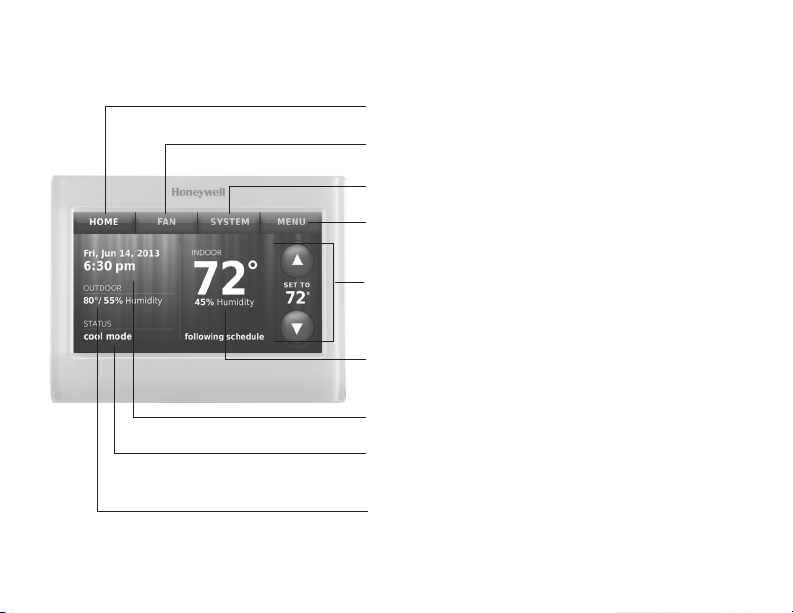
Quick reference: home use
HOME. Touch to display Home screen.
FAN. Select fan mode.
SYSTEM. Select system mode (heat/cool).
MENU. Touch to display options. Start here to
set a program schedule.
Current schedule. Change temperature
setting and select temporary or permanent
hold.
Indoor conditions. Shows indoor temperature
and humidity.
Current date and time.
Current status. Shows system mode (heat/
cool).
Outdoor conditions. Outdoor temperature
and humidity appear after registration.
69-2809EF—03 4
Page 7
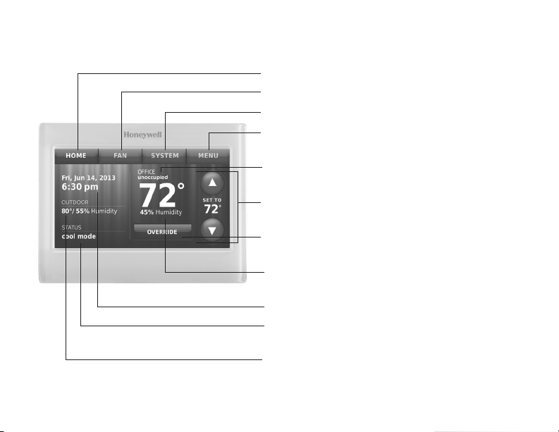
Quick reference: business use
HOME. Touch to display Home screen.
FAN. Select fan mode.
SYSTEM. Select system mode (heat/cool).
MENU. Touch to display options. Start here to
set a program schedule.
Thermostat location. Quickly identify which
thermostat is in control of a specific area.
Current schedule. Touch an arrow to change
temperature setting and set a temporary hold.
Override. Touch to temporarily override the
program schedule.
Indoor conditions. Shows indoor temperature
and humidity.
Current date and time.
Current status. Shows system mode (heat/
cool).
Outdoor conditions. Outdoor temperature
and humidity appear after registration.
5 69-2809EF—03
Page 8

Setting up your thermostat
Setting up your Wi-Fi programmable touchscreen thermostat is easy. It is
preprogrammed and ready to go as soon as it is installed and registered.
Install your thermostat.
1
Connect it to your home wireless network.
2
3
Register online for remote access.
Before you begin, you may want to watch a brief installation video.
Use the QR Code
®
at the front of this guide, or go to
wifithermostat.com/support
69-2809EF—03 6
Page 9
Installing your thermostat
You might need the following tools to install this thermostat:
• No. 2 Phillips screwdriver
• Pen
• Pencil
• Level (optional)
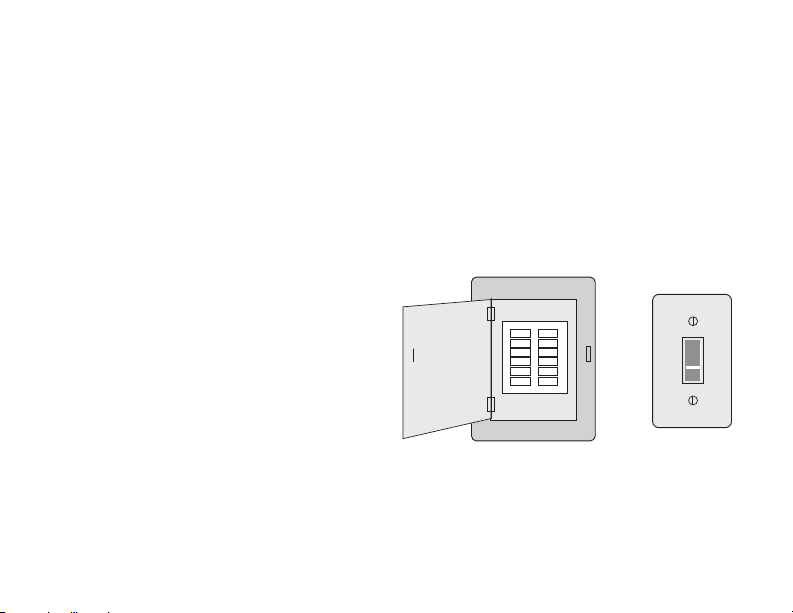
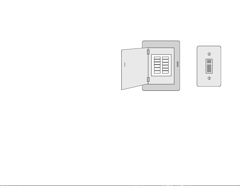
1 Switch OFF power to your
heating/cooling system.
Important! To protect your
equipment, switch OFF the power
to your heating/cooling system
at the breaker box or the system
switch.
7 69-2809EF—03
• Drill and bits (3/16” for drywall,
7/32” for plaster) (optional)
• Hammer (optional)
• Electrical tape (optional)
or
Circuit
breaker
box
Heating/cooling
system power
switch
Page 10
Installing your thermostat
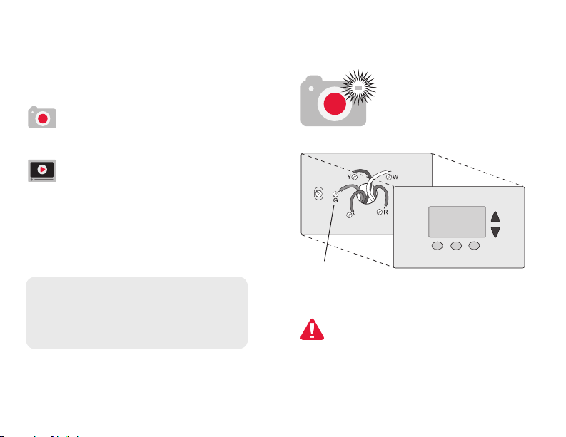
2 Remove old thermostat faceplate
and leave wires connected.
2a Take a picture of the
wire connections for later
reference.
2b If no wire is connected to
a terminal labeled C or no
C terminal exists on the
old thermostat, view the
Alternate Wiring videos at
wifithermostat.com/videos
Important! C wire is required
and is the power source for your
thermostat. Without a C wire, your
thermostat will not power up.
69-2809EF—03 8
Note: You will need a
picture of your wire
connections to wire the
new thermostat.
C
Terminal
designation
If you have an older thermostat
with a sealed mercury tube, turn
to page 2 for proper disposal
instructions.
Page 11
Installing your thermostat
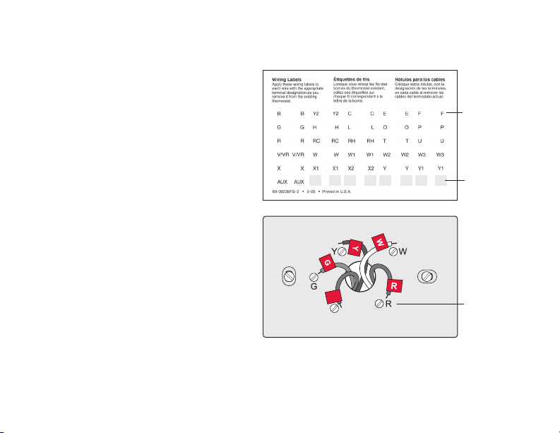
3 Label the wires.
Use the supplied sticky tags
to label each wire as you
disconnect it. Label wires
according to the old thermostat
terminal designations, not by
wire color.
Note: If no tag matches a
terminal designation, write the
appropriate letter on a blank
sticky tag.
4 Remove wallplate.
Remove the old wallplate from
the wall after all wires have been
labeled and disconnected.
C
C
Note: Wrap the wires around
a pencil to prevent them from
falling back into the wall.
9 69-2809EF—03
Sticky tag
Blank tags
Terminal
designation
Page 12
Installing your thermostat
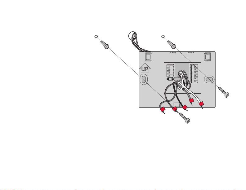
5 Mount wallplate for Wi-Fi
thermostat.
Mount your new wallplate
using screws and anchors
included with the thermostat.
If necessary:
Drill 3/16-in holes for drywall.
Drill 7/32-in holes for plaster.
Note: You may be able to use
your existing wall anchors. Hold
the wallplate up to the existing
anchors to check for alignment.
69-2809EF—03 10
C
K
Rc
R
C
G
Wallplate
LEVEL
HERE
WO/B
Y
G
W2Aux/E
Y2
L
Y
W
R
MCR34499
Page 13

Installing your thermostat
Important! The Wi-Fi thermostat requires a C wire to operate. The C, or common, wire
brings 24 VAC power to the thermostat. Many older mechanical or battery operated
thermostats do not require a C wire. If you don’t have a C wire, try:
• Looking for an unused wire that is pushed into the wall. Connect that wire to C and
check that it is connected to the 24 VAC common at your heating/cooling system.
Check the video section at wifithermostat.com
Note: Not all heating/cooling systems label the 24 VAC common C. Check your system
manual or contact the manufacturer to find out which terminal is the 24 VAC common.
View the Alternate Wiring videos at wifithermostat.com/videos
Wiring
For conventional heating/cooling systems (natural gas, oil or electric furnace, air
conditioner), see page 12. See “Glossary” on page 73 for further definition.
For a heat pump system, see page 14. See “Glossary” on page 73 for further
definition.
11 69-2809EF—03
Page 14
Installing your thermostat
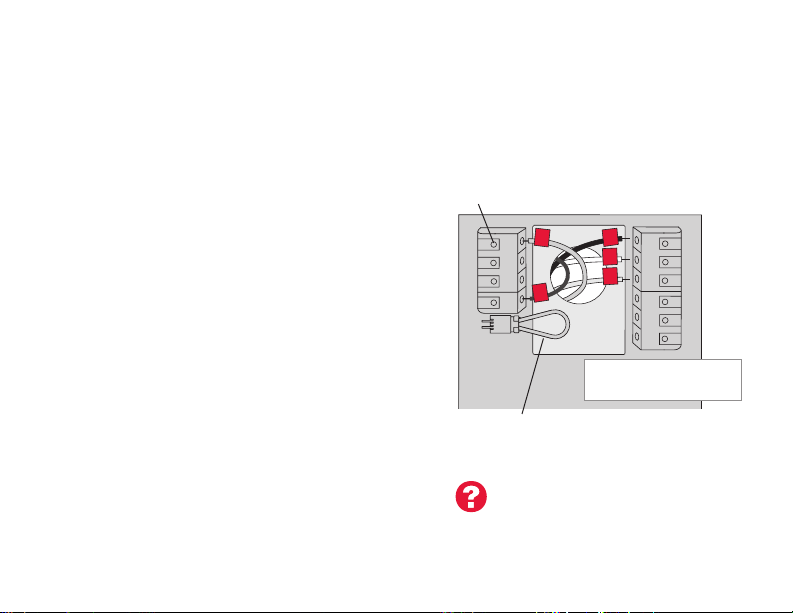
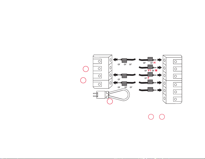
Wiring (Conventional System)
6A Wire the Wi-Fi thermostat to your
conventional system.
a Starting with the C Wire, match the
sticky tag on the wire to the terminal
labels.
You must have a C wire. See page 11.
Straighten wire and gently slide
b
terminal hole until it clicks into place.
(If you need to remove a wire, use a
pen tip to press the terminal release
and then pull wire out.)
Note: Refer to the wiring picture you took
in Step 2.
Tip: To make it easier to slide the wire
into place, use a pen tip to hold down the
terminal release.
69-2809EF—03 12
into
Note: The wiring for your
application might be different than
the wiring shown below.
Terminal release
Rc
C
K
R
C
R
W
Y
G
EXAMPLE WIRING
Yours may look different
WO/B
Y
G
W2-
Aux/E
Y2
L
Remove jumper loop ONLY if
you have both R and Rc wires.
Labels don’t match?
See alternate wiring keys
on pages 16-17.
Page 15
Installing your thermostat
Wiring (Conventional System
continued)
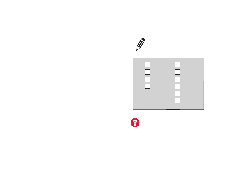
c In the image on the right, check the
box next to each connection. You will
use this checklist in Step 9.
d Verify wire is firmly secured by gently
pulling on wire.
e Repeat steps a–d for all other wires.
f Push any excess wire back into the
wall opening after all wires are
installed.
g Continue to page 20.
13 69-2809EF—03
Important!
Check the box for each wire
you connect. You will need
this information in Step 9.
C
K
Rc
R
Labels don’t match?
See alternate wiring keys
on pages 16-17.
W-O/B
Y
G
W2Y2
L
Aux/E
Page 16
Installing your thermostat
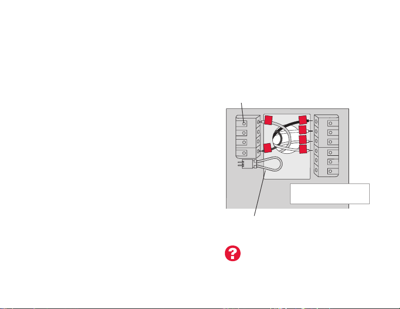
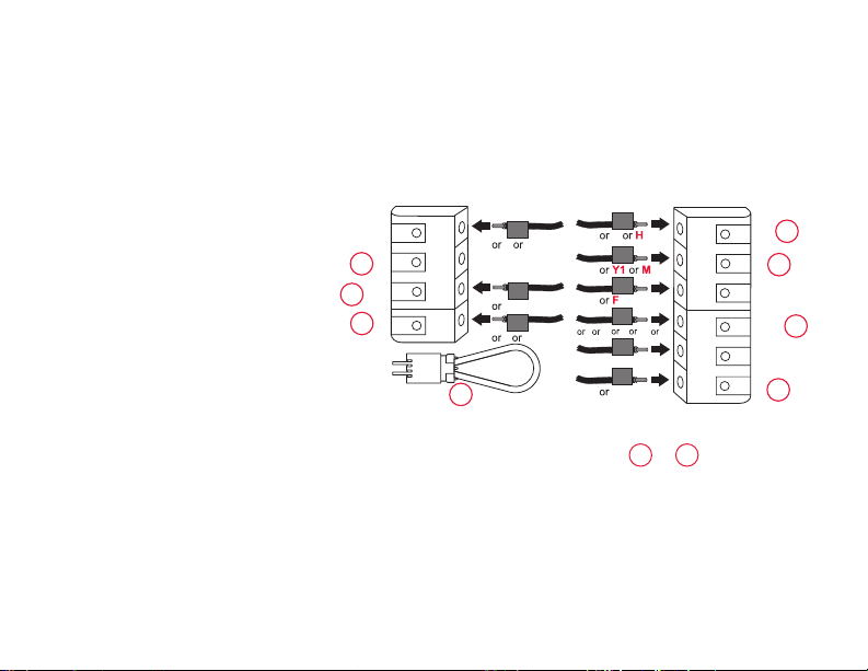
Wiring (Heat Pump System)
6B Wire Wi-Fi thermostat to your heat pump.
a Starting with the C Wire, match the
sticky tag on the wire to the terminal
labels.
You must have a C wire. See page 11.
b Slide wire gently into terminal hole
until it clicks into place. (If you need
to remove a wire, use a pen tip to
press the terminal release and then
pull the wire out.)
Note: Refer to the wiring picture you took
in Step 2.
Tip: To make it easier to slide the wire
into place, use a pen tip to hold down the
terminal release.
69-2809EF—03 14
Note: The wiring for your
application might be different than
the wiring shown below.
Terminal release
O
Y
G
AUX
EXAMPLE WIRING
Yours may look different
WO/B
Y
G
W2-
Aux/E
Y2
L
Rc
C
K
R
C
R
Remove jumper loop ONLY if
you have both R and Rc wires.
Labels don’t match?
See alternate wiring keys
on pages 18-19.
Page 17
Installing your thermostat
Wiring (Heat Pump System
continued)
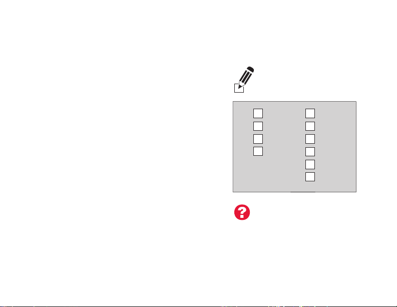
c In the image on the right, check the
box next to each connection. You will
use this checklist in Step 9.
d Verify wire is firmly secured by gently
pulling on wire.
e Repeat steps a–d for all other wires.
Note: If old thermostat has separate
wires on AUX and E, use a wire nut to
attach both wires to a separate wire.
Slide this third wire into the W2-Aux/E
terminal.
f Push any excess wire back into the
wall opening after all wires are
installed.
g Continue to page 20.
15 69-2809EF—03
Important!
Check the box for each wire
you connect. You will need
this information in Step 9.
C
K
Rc
R
Labels don’t match?
See alternate wiring keys
on pages 18-19.
W-O/B
Y
G
W2-
Y2
L
Aux/E
Page 18
Installing your thermostat
Alternate wiring (Conventional System)
Use this if your wire labels
don’t match the terminal labels.
Note: You must have a C wire
or equivalent. See page 11.
C
1
K
Rc
2
R
69-2809EF—03 16
C
B
X
C1
Rc
R
R
V
4
RH
2
See key to
W
W1
Y
G
W2
Y2
1
– 2 on page 17.
WO/B
Y
G
W2-
Aux/E
Y2
L
Page 19

Installing your thermostat
Alternate wiring key (Conventional System)
Do not use K terminal. For future use.
1
• IfyouhavebothanR and Rc wire, unplug the jumper loop by pulling on the wire
2
loop.
• IfyouroldthermostathadbothR and RH wires, connect the R wire to the Rc
terminal, the RH wire to the R terminal, and unplug the jumper loop.
17 69-2809EF—03
Page 20
Installing your thermostat
Alternate wiring (Heat Pump System)
Use this if your wire labels
don’t match the terminal labels.
Note: You must have a C wire
or equivalent. See page 11.
C
1
K
2
Rc
3
R
X X2
B
AUX
F
O
Y
G
Y2
W W1
L
W2
C
B
X
Rc
R
R
VR
V
2
WO/B
Y
G
W2-
Aux/E
Y2
L
4
5
6
7
69-2809EF—03 18
See key to
1
– 7 on page 19.
Page 21

Installing your thermostat
Alternate wiring key (Heat Pump System)
1
Do not use K terminal. For future use.
2
Leave jumper loop in place.
If your old thermostat had both V and VR wires, check wifithermostat.com for help.
3
If your old thermostat had separate O and B wires, attach the B wire to the C
4
terminal. If another wire is attached to the C terminal, check wifithermostat.com
for help. Attach the O wire to the O/B terminal. On the Type of Changeover Valve
screen, select Cooling Changeover Valve. See page 66. If your old thermostat
had an O wire and not a B wire, attach the O wire to the O/B terminal.
If your old thermostat had separate Y1, W1, and W2 wires, check
5
wifithermostat.com for help.
If the old thermostat has separate wires on Aux and E, use a wire nut to attach
6
both wires to a separate wire. Slide this third wire into the W2-Aux/E terminal.
This is the system monitor. If the monitor finds a problem, you will see an orange
7
alert button on the thermostat home screen.
19 69-2809EF—03
Page 22
Installing your thermostat
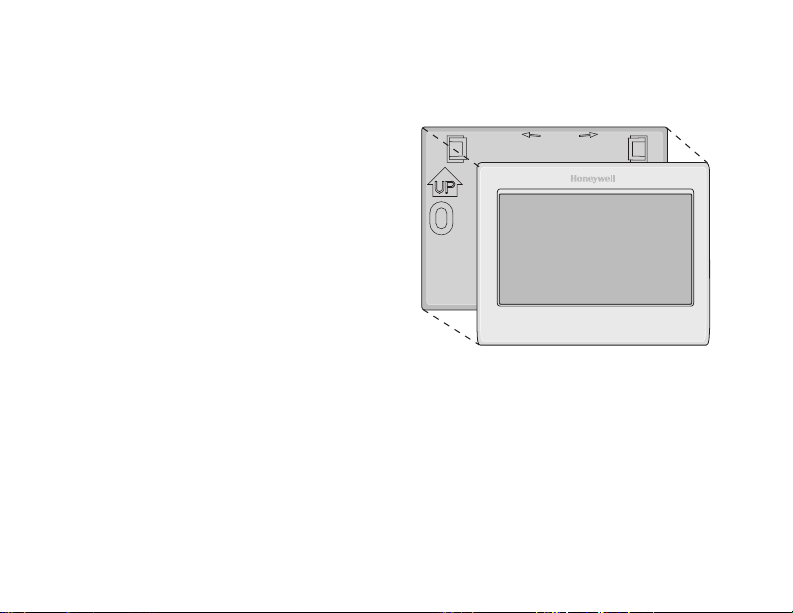
7 Attach thermostat to wallplate.
Align the thermostat with the
wallplate and then snap into place.
69-2809EF—03 20
Wallplate
LEVEL
HERE
Thermostat
Page 23
Installing your thermostat
8 Switch heating/cooling system ON.
Important!
8a Verify that the C wire is
connected at the thermostat and
at the heating/cooling system.
8b Make sure the heating/cooling
system door is firmly secured.
8c Switch power back ON for your
heating/cooling system at the
breaker box or its power switch.
21 69-2809EF—03
Circuit
breaker
box
or
Heating/cooling
system power
switch
Page 24
Installing your thermostat
Before connecting to your Wi-Fi network,
you need to set initial thermostat options
to define your heating/cooling system:
• Language
• Homeorbusiness
You can customize other options later.
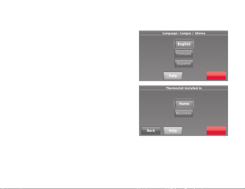
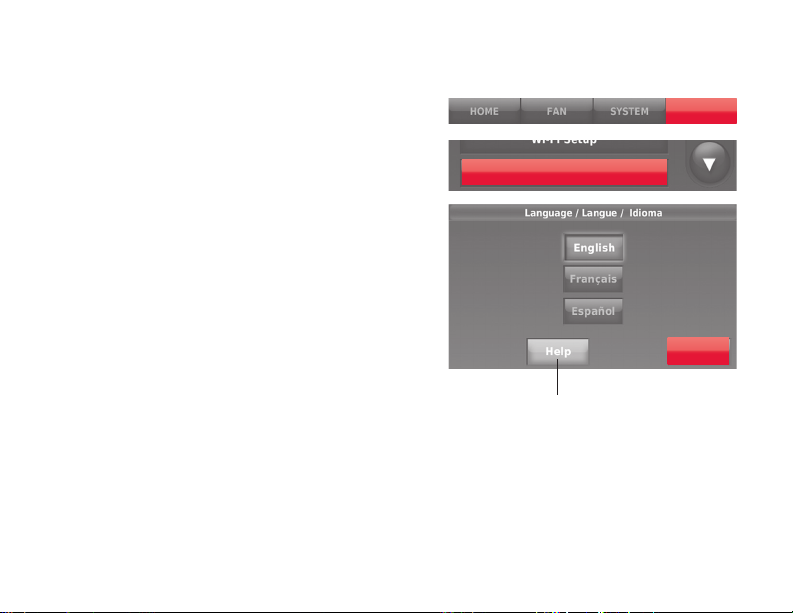
9 Follow prompts on the screen to select
appropriate options.
9a Touch the language you want the
thermostat to display, then touch
Next.
9b Select Home or Business
installation, then touch Next.
69-2809EF—03 22
Next
Next
Page 25
Installing your thermostat
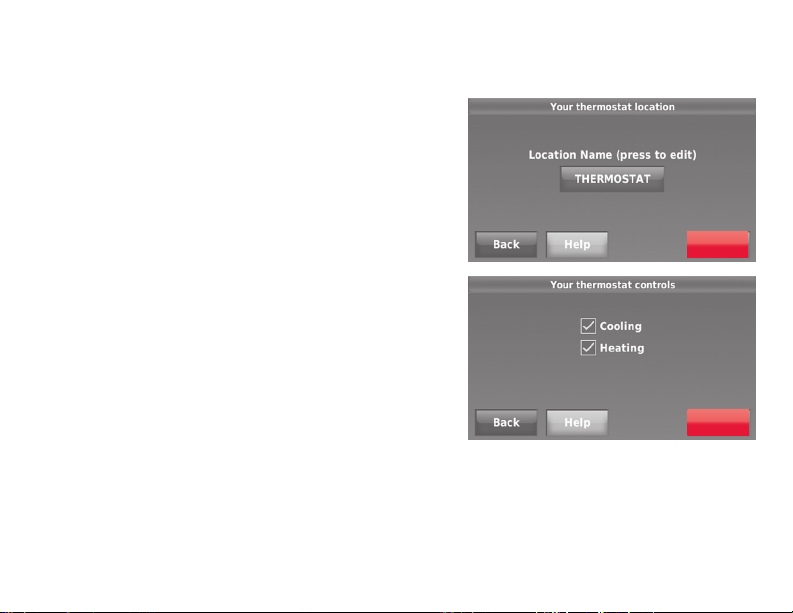
9c Touch Next, or name the thermostat
location—touch THERMOSTAT and
follow the rest of the instructions.
9d Select what your thermostat will
control and touch Next.
Note: Touch the orange Help button on any
screen for more information.
23 69-2809EF—03
Next
Next
Page 26
Installing your thermostat
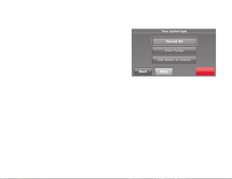
9e Select your system type and touch
Next. The system type determines
other selections for completing initial
setup. Use the checklist from Step
6d when making selections.
9f Touch Next after making selections
on each screen.
9g Touch Done on the last screen. The
thermostat displays an option to
connect to your Wi-Fi network.
Note: Touch the orange Help button on
any screen for more information.
69-2809EF—03 24
Next
Page 27
Connecting to your Wi-Fi network
After touching
Done
on the final screen of the
initial set up (page 24), the thermostat displays
an option to connect to your Wi-Fi network.
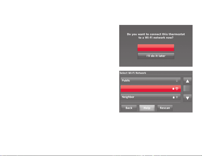
1 Connect the Wi-Fi network.
Touch Yes to connect the thermostat to your
Wi-Fi network. The screen displays the
message “Searching for wireless networks.
Please wait...” after which it displays a list of
all Wi-Fi networks it can find.
Yes
Note: If you cannot complete this step now,
touch
I’ll do it later
. The thermostat will display
Your Network
the home screen. Complete this process by
selecting
MENU
>
Wi-Fi Setup
. Continue with
Step 2.
2 Select the network.
2a Touch the name of the network you
want to use. The thermostat displays a
password page.
25 69-2809EF—03
Note: If your home network is not
shown on the list, touch
Rescan
.
Page 28
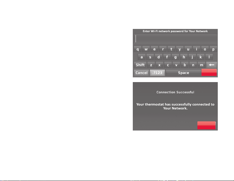
Connecting to your Wi-Fi network
2b Using the keyboard, touch the
characters that spell out your home
network password.
2c Touch Done. The thermostat displays
“Connecting to your network. Please
wait...” then shows a “Connection
Successful” screen.
2d Touch Next to display the registration
information screen.
2e Note your Thermostat MAC and
Thermostat CRC. You need these
numbers to complete online
registration.
69-2809EF—03 26
Done
Next
Page 29
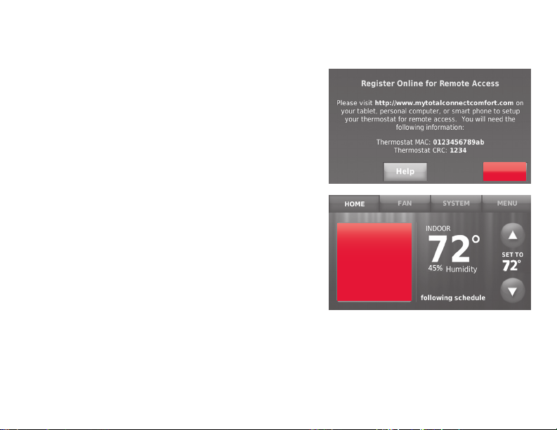
Connecting to your Wi-Fi network
To register your thermostat, follow the
instructions beginning on page 30.
Note: The Register Online screen remains
active until you complete registration and/or
touch Done.
Note: If you touch Done before you register
online, your home screen displays an
orange alert button telling you to register.
Touching that button displays registration
information and an option to snooze the
task.
27 69-2809EF—03
Register
online for
remote
access
Press for info
Done
Page 30
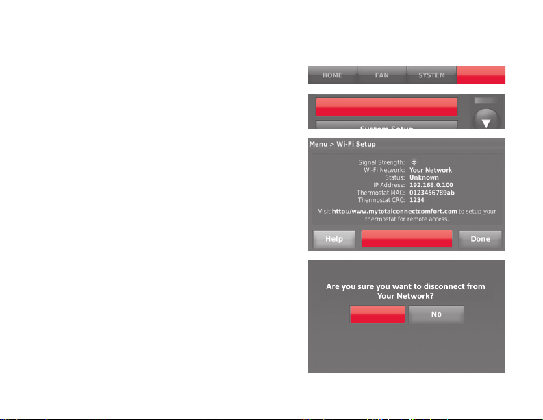
Disconnecting your Wi-Fi network
1 Touch MENU.
2 Select Wi-Fi Setup.
3 Touch Disconnect from Network. The
thermostat will display a question to
confirm your selection.
4 Touch Yes to confirm that you want
to disconnect from the network. The
thermostat will display the Wi-Fi Setup
screen.
5 Touch OK to display the menu.
69-2809EF—03 28
Wi-Fi Setup
Disconnect from
Network
Yes
MENU
Page 31

Reconnecting your Wi-Fi network
1 Touch MENU.
2 Select Wi-Fi Setup.
3 Touch the name of the network you want
to use. The thermostat may display a
password page.
4 To enter a password, touch characters to
spell out your home network password,
then touch Done.
5 The thermostat displays “Connecting
to your network. Please wait...” then a
“Connection Successful” screen.
6 Touch Next.
• Ifyourthermostatisregistered,you
will see your signal strength and other
status information. Touch Done.
• Ifthescreendisplays“Register
Online for Remote Access,” follow
instructions on page 30.
29 69-2809EF—03
Wi-Fi Setup
MENU
Page 32

Registering your thermostat online
To view and set your Wi-Fi thermostat
remotely, you must have a Total Connect
Comfort account. Use the following steps.
1 Open the Total Connect Comfort web
site.
Go to mytotalconnectcomfort.com
View the Wi-Fi Thermostat
Registration video at
wifithermostat.com/videos
69-2809EF—03 30
M31570
Page 33

Registering your thermostat online
2 Login or create an account.
If you have an account,
click Login
– or –
click Create An Account
2a Follow the instructions on the screen.
2b Check your email for an activation
message from My Total Connect
Comfort. This may take several
minutes.
Note: If you do not receive a response,
check your junk mailbox or use an alternate
e-mail address.
2c Follow activation instructions in
the email.
2d Log in.
31 69-2809EF—03
Page 34

Registering your thermostat online
3 Register your Wi-Fi thermostat.
Thermostat ID Card
After you are logged in to your Total
Connect Comfort account, register
your thermostat.
3a Follow the instructions on
the screen. After adding your
thermostat location, you must
enter the thermostat’s unique
identifiers:
• MACID
• MACCRC
Note: These IDs are listed on the
Register Online screen or on the
Thermostat ID Card included in the
thermostat package. The IDs are not
case sensitive.
69-2809EF—03 32
Use the MAC ID and CRC ID to register
this product at mytotalconnectcomfort.com
Carte d’identification de thermostat
Utilisez l’identication MAC et l’identication CRC pour
enregistrer ce produit à mytotalconnectcomfort.com
Tarjeta de identificación del termostato
Utilice la identicación MAC y la identicación CRC para
inscribir este producto en mytotalconnectcomfort.com
® U.S. Registered Trademark.
© 2012 Honeywell International Inc.
69-2723EFS—01 M.S. 04-12
Printed in U.S.A.
MAC ID MAC CRC
HONEYWELL MODEL: RTH8580WF
MAC ID: MAC CRC:
69-2723EFS-01
Page 35

Registering your thermostat online
When the thermostat is
successfully registered, the Total
Connect Comfort registration
screen will display a SUCCESS
message.
You can now control your
thermostat from anywhere
through your laptop, tablet, or
smartphone.
Total Connect Comfort free
app is available for Apple®
®
iPhone
, iPad® and iPod
GET IT ON
Download on
iTunes
touch® devices at iTunes®
or at Google Play® for all
Android™ devices.
33 69-2809EF—03
Page 36

Setting the time/date
1 Touch the current time. The screen
displays Set Time/Set Date.
2 Touch Set Time or Set Date.
3 Touch p or q until the proper time/
date is displayed.
4 Touch Done to save or Cancel to ignore
changes.
Note: This thermostat will automatically
update for daylight saving time (if
observed in your area) and all date/time
information is stored. If the thermostat
is connected to Wi-Fi and registered to
Total Connect Comfort, the current time is
updated from the internet.
69-2809EF—03 34
Fri, Jun 14, 2013
6:30 pm
30
Done
Page 37

Setting the fan
1 Touch FAN to display fan settings.
FAN
2 Touch On, Automatic, Circulate, or Follow
Schedule.
Done
3 Touch Done to save and exit.
On: Fan is always on.
Automatic: Fan runs only when the
heating or cooling system is on.
Circulate: Fan runs randomly about
35% of the time (home use only).
Follow Schedule: Fan controlled by
program (see pages
37
-42).
Note: Touch Auto or On to temporarily
override the programmed fan schedule.
35 69-2809EF—03
Page 38

Setting system mode
1 Touch SYSTEM to display system settings.
2 Touch desired option:
Heat: Thermostat controls only the
heating system.
Cool: Thermostat controls only the
cooling system.
Off: Heating/cooling systems are off.
Automatic: Thermostat selects heating
or cooling as needed depending on the
indoor temperature.
Emergency Heat (heat pumps
with aux. heat): Controls auxiliary/
emergency heat. Compressor is locked
out.
3 Touch Done to save and exit.
Note: The Automatic and Emergency Heat
system settings may not appear, depending
on how your thermostat was installed.
69-2809EF—03 36
SYSTEM
Done
Page 39
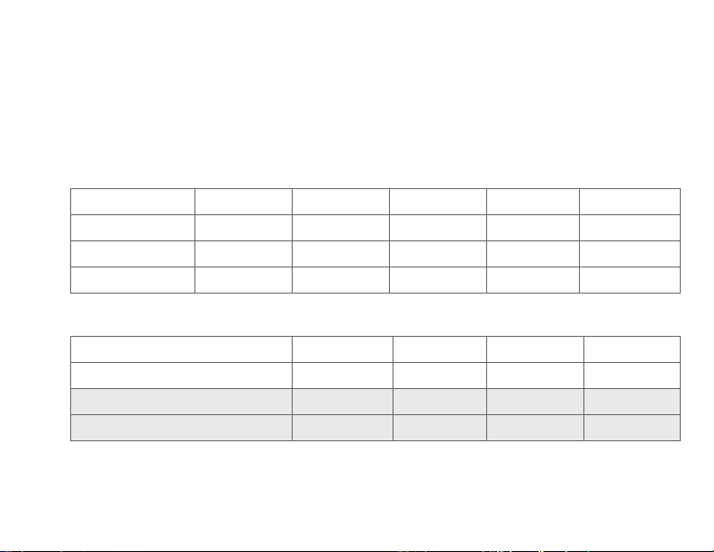
Preset energy-saving schedules
This thermostat uses default Energy Saver settings that can reduce your heating/
cooling expenses. To customize settings, see next page.
(Mon-Fri)Start time
Cool
Heat
(Sat-Sun)
CoolStart time HeatPeriod Fan
(Sat-Sun)
Cool
Heat
(Mon-Fri)Period
Wake 6:00 am 70° 78° 70° 78°
Leave 8:00 am 62° 85° 62° 85°
Return 6:00 pm 70° 78° 70° 78°
Home Use
Sleep 10:00 pm 62° 82° 62° 82°
Occupied 1 8:00 am 70° 75° On
Unoccupied 1 10:00 pm 55° 85° Auto
Occupied 2* 12:00 am 70° 75° On
Unoccupied 2* 12:00 am 55° 85° Auto
Business Use
* Period 2 is cancelled by default. If you activate it, the values shown above are
default settings.
37 69-2809EF—03
Page 40

Adjusting program schedules
1 Touch MENU.
2 Select Create/Edit Schedule.
• TouchView/Edit to view the full
schedule and make a quick
adjustment.
• TouchGuide Me to create a schedule
by answering simple questions.
• TouchI’ll do it myself to manually
create a program schedule. See
page 39.
Note: To reduce costs, use the pre-set
Energy Saver settings described on
page 37.
69-2809EF—03 38
MENU
Create / Edit Schedule
Page 41

Adjusting program schedules
If you selected I’ll do it myself on the Create/
Edit Schedule screen (page 38), follow
these steps:
1 Select the days to schedule, touch Next.
2 Touch Wake to set your Wake time for
selected days.
Heat: 70°
Cool: 78°
Fan: Auto
6:00 am
WAKE
39 69-2809EF—03
Next
Page 42
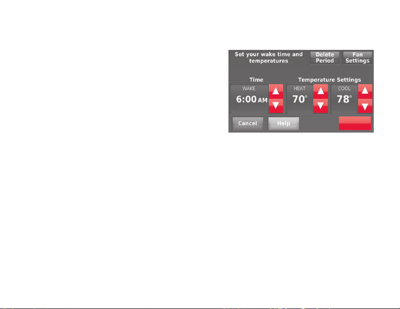
Adjusting program schedules
3 Touch p or q to set Heat and Cool
temperatures for the Wake period, then
touch Done.
4 Touch other time periods (Leave, Return,
Sleep) to set time and temperatures for
each.
5 Touch Done to save and exit.
Note: Touch Delete Period to eliminate any
unwanted time period.
Note: Touch Fan Settings to customize fan
settings for any time period.
69-2809EF—03 40
Done
Page 43
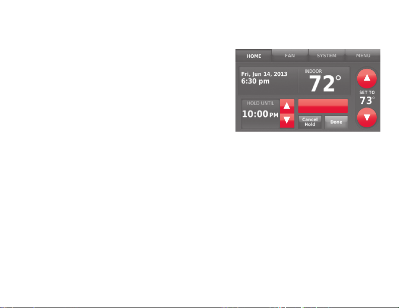
Overriding schedules: home use
1 Touch p or q to adjust the
temperature (right side of screen)
and the Hold Until time (left side). The
schedule will resume when the Hold
Until time expires.
2 Touch Switch to Permanent Hold to keep
the same temperature until you change
it or resume the program schedule.
3 Touch Cancel Hold at any time to
resume the program schedule.
41 69-2809EF—03
Switch To
Permanent Hold
Page 44
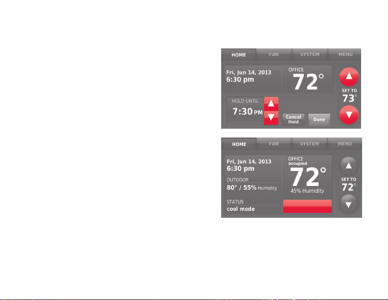
Overriding schedules: business use
Touch p or q to adjust the temperature.
It will be maintained until the hold time
you set.
• To change the hold time, touch the
Hold Until arrow buttons. This time can
be adjusted up to the maximum time
set on the Override Duration screen in
Advanced Preferences (page 61).
• Touch Override to use a pre-set occupied
temperature if a person uses the room
during an unoccupied period. The new
temperature will be maintained for 1 hour
and can be adjusted up to the maximum
time set on the Override Duration screen
in Advanced Preferences (page 61).
The programmed schedule will resume when
the override timer expires. Touch Cancel Hold
at any time to resume the program schedule.
69-2809EF—03 42
OVERRIDE
Page 45

Viewing equipment status
1 Touch MENU.
MENU
2 Select Equipment Status.
3 Touch p or q to view the status of
all the equipment your thermostat
is controlling. Depending on how
your thermostat was installed, the
Equipment Status screen can report
data about the following systems:
Equipment Status
• Heatingandcooling
• Fan
• Thermostatinformation
Done
43 69-2809EF—03
Page 46

Setting vacation hold: home use
This feature helps you save energy while
you are away, and restores comfortable
settings just before you return home.
1 Touch MENU.
2 Select Vacation Mode.
3 Touch p or q to select the date you
leave, then touch Next for further
scheduling details, including times of
day, temperature settings, return date,
and return settings.
4 Review your selections on the last
display, and touch Done to save your
settings. Touch Back, then Cancel to
ignore the changes.
69-2809EF—03 44
MENU
Vaca�on Mode
Next
Done
Page 47

Setting holiday/event schedules: business use
This feature helps you conserve energy
MENU
when the workplace is unoccupied for
special events and holidays.
Holiday / Event Scheduler
1 Touch MENU.
2 Select Holiday/Event Scheduler.
3 Select the item you want to schedule.
• CustomEventsletsyousetup
Custom events
other days for special schedules.
• USandCanadianHolidayoptions
let you select from a list of holidays
commonly observed in each
country.
4 Make selections as prompted on each
screen. For more information, see next
two pages.
5 Touch Done to save your settings.
45 69-2809EF—03
Page 48

Setting custom events: business use
This feature lets you customize
temperature settings to be maintained
during a specific event. You can set up an
event for a specific date or day in a month.
The thermostat resumes normal scheduling
after the event.
1 Select Custom events from the Holiday/
Event Scheduler menu.
2 Select Create a new event.
69-2809EF—03 46
Custom events
Create a new event
Page 49

Setting custom events: business use
3 Select Specific Date or Month/Weekday.
• ForSpecific Date, you are prompted
to select the start date, settings,
end date, and frequency for the
event.
• ForMonth/Weekday, you are
prompted to select the month, day
of the week, week of the month,
settings, length of event, and
frequency of the event.
4 Review the settings and touch Done to
save them. Touch Back, then Cancel to
ignore the changes.
47 69-2809EF—03
Next
Done
Page 50

Setting holiday schedule: business use
This feature lets you customize temperature
settings to be maintained on specified national
holidays. The thermostat resumes normal
scheduling between selected holidays.
1 Select US Holidays or Canadian Holidays from
the Holiday/Event Scheduler menu.
2 Select Add/Edit Holidays. A list of national
holidays is displayed.
3 Touch the check box next to each holiday for
which you want to maintain specific settings,
(Touch p or q to scroll through the holiday
list.) then touch Next.
Set the holiday schedule for Occupied
or Unoccupied temperatures, depending
whether the building will be in use.
4 Touch p or q to select the Heat and Cool
temperatures.
5 Review the settings and touch Done to save
them. Touch Back, then Cancel to ignore the
changes.
69-2809EF—03 48
Next
Page 51

Setting holiday override: business use
This feature lets you customize temperature
MENU
settings to be maintained from now until
a specified date. The thermostat resumes
normal scheduling on the date you select.
Holiday Mode
1 Touch MENU.
2 Select Holiday Mode to display
temperatures while you are away on
holiday.
3 Touch p or q to select the Heat and
Cool temperatures, then touch Next to
select return date.
4 Review the settings and touch Done to
save them. Touch Back, then Cancel to
ignore the changes.
Note: The cool temperature can only be set
higher than the unoccupied program setting
and the heat temperature can only be set
lower than the unoccupied program setting.
49 69-2809EF—03
Done
Page 52

Initiating occupancy mode: business use
This feature keeps temperature at an
energy-saving level until you touch Press
to start occupancy. When you arrive, touch
the button to maintain a comfortable
temperature while the room is occupied.
Touch the p or q buttons to set the
temperature or the Hold Until time. The
temperature is maintained until the time
you set. Temperature returns to an energysaving level after the timer expires, or the
“Occupied” period ends.
69-2809EF—03 50
Press to start
occupancy
Page 53

Customizing screen color
You can customize your thermostat display
MENU
to match your décor.
1 Touch Menu.
Color Themes
2 Touch Color Themes.
3 Select the name of a color to use
a predefined background, or select
Custom to define you own background
color and text.
• Ifyouselectacolorname,the
screen shows an example on the left.
Touch Done to accept that selection.
Done
• IfyoutouchCustom, the screen gives
you instructions. Touch Next to step
through the choices; touch Done
when you are satisfied with your
changes.
Next
51 69-2809EF—03
Page 54

Setting preferences
Preference menu options let you select
how the thermostat displays information or
responds to certain situations.
1 Touch MENU and select Preferences.
2 Select an option and follow prompts:
• Reminders
• UtilityScheduleOptions
• Backlight
• SmartResponseTechnology
• AdvancedPreferences
• RestoreDefaultSchedule
3 Touch Done to save your settings.
Touch Cancel to ignore changes.
69-2809EF—03 52
MENU
Preferences
Page 55

Cleaning the thermostat screen
When you select the Clean Screen
MENU
option, the screen is locked so you don’t
accidentally change settings while you
clean.
Clean Screen
1 Touch MENU.
2 Select Clean Screen. A prompt asks if you
want to clean the screen for 30 seconds.
3 Touch Yes. A countdown timer displays
elapsed time until the screen is
Yes
reactivated.
Note: Do NOT spray any liquid directly
on the thermostat. Spray liquids onto a
cloth, then use the damp cloth to clean
the screen. Use water or household glass
cleaner. Avoid abrasive cleansers.
53 69-2809EF—03
Page 56

Adjusting security settings
You can adjust security options to prevent
unauthorized changes to system settings.
1 Touch MENU and select Security Settings.
2 Select Change Lock Mode.
3 Select an option and follow prompts:
Unlocked: Full access allowed.
Partially locked: Only temperature
can be changed.
Fully locked: No access allowed.
Note: If you choose to use a password for
additional security, write it here for reference:
69-2809EF—03 54
MENU
Security Se�ngs
Change Lock Mode
Page 57

Software updates
Honeywell periodically issues updates
to the software for this thermostat. The
updates occur automatically through your
Wi-Fi connection. All your settings are
saved, so you will not need to make any
changes after the update occurs.
Updates occur in the early morning. After
your thermostat receives the software, it
reboots, briefly displaying the Honeywell
logo. The screen then shows “Updating
software…” with a green progress bar.
When the update is complete, your home
screen will appear as usual.
Note: If you are not connected to Wi-Fi or
registered at Total Connect Comfort, you
will not get automatic updates.
55 69-2809EF—03
Page 58

Unregistering your thermostat
If you remove the thermostat from your
Total Connect Comfort website account
(for example, you’re moving and leaving
the thermostat behind), follow these
steps:
1 On mytotalconnectcomfort.com log
into your account.
2 Under My Account, select Edit My
Profile.
3 Click the Delete My Account button.
Your thermostat will display an orange
button that says Register Online.
69-2809EF—03 56
Page 59

Smart Response Technology
This feature (home use only) allows the
thermostat to “learn” how long the heating/
cooling system takes to reach programmed
temperature settings, so the temperature is
reached at the time you set.
For example: Set the Wake time to 6:00 am,
and the temperature to 70°. The heat will
come on before 6:00 am, so the temperature
is 70° by 6:00 am.
Note: Select Smart Response Technology
in the Preferences menu (page 52).
The message “in recovery” is displayed
when the system is activated before a
scheduled time period.
57 69-2809EF—03
Page 60

Pre-occupancy purge
This business use feature turns on the
fan 1 to 3 hours before each “occupied”
time period, to provide a comfortable
work environment when you arrive.
69-2809EF—03 58
Page 61

Compressor protection
The thermostat keeps the compressor
off for a few minutes before restarting,
to prevent equipment damage. During
this “off” time, the message “waiting for
equipment” is displayed on screen.
59 69-2809EF—03
Page 62

Auto changeover
This feature is used in climates where
both air conditioning and heating are used
on the same day.
When the system is set to Automatic, the
thermostat automatically selects heating
or cooling depending on the indoor
temperature.
Heat and cool settings must be at least
3 degrees apart. The thermostat will
automatically adjust settings to maintain
this 3-degree separation.
Note: Select Auto Changeover on the
Heating and Cooling System Changeover
screen under Advanced Preferences. See
“Setting advanced preferences” on page
61.
69-2809EF—03 60
Page 63

Setting advanced preferences
You can change options for a number of
MENU
system functions. Although many options,
such as language and temperature indication
Preferences
settings are the same for all setups, others
depend on the type of system you have.
1 Touch MENU. The thermostat displays a
list of options.
2 Select Preferences > Advanced Preferences.
The thermostat displays the first screen of
options that you can change.
Advanced Preferences
3 On each screen, make changes as
needed, then touch Next to display new
options. Repeat this step until you have
made all changes.
Tables on pages 62-63 explain the
screens and options under Advanced
Preferences.
4 When you have made all changes, press
Next
Done to save and exit.
61 69-2809EF—03
Page 64

Setting advanced preferences
Advanced Preferences Options (MENU > Preferences > Advanced Preferences)
Screen Title Settings and Options
Scheduling Options
Temperature Indication
Scale
Heating and Cooling
System Changeover
Number of Schedule
Periods
Pre-occupancy Purge
Duration
Type of Override
Override Duration
69-2809EF—03 62
Select Non-programmable or Programmable. Programmable uses
default or customized programming to automatically raise and
lower temperature settings for different times of day.
Select Fahrenheit or Celsius.
Select Manual or Automatic.
Select 2 Periods Per Day or 4 Periods Per Day. (see page 37).
Select how long the fan will run before each occupied period: Off,
1, 2, or 3 hours.
Select Standard to maintain the programmed periods or Initiate
Occupancy to use energy-saving settings until a user presses
Start Occupancy.
Select how long to maintain temperature during an override: 1-10
hours or No Limit.
Page 65

Setting advanced preferences
Advanced Preferences Options (concluded)
Screen Title Settings and Options
Early Recovery for Heating
Early Recovery for Cooling
Temperature Limits Select the Minimum Cool and Maximum Heat Limit.
Keypad Lockout Select Unlocked/Partially Locked/Locked.
Clock Format Select 12 Hour or 24 Hour.
Daylight Saving Time
Indoor Display Offsets
63 69-2809EF—03
Select No to begin recovery on schedule or Yes to ramp up
temperature early.
Select No to begin recovery on schedule or Yes to ramp down
temperature early.
Select Off or On. If set to On, the system will automatically change
time/date to account for daylight saving.
Select the number of degrees to offset indoor temperature or
percentage to offset indoor humidity.
Page 66
Changing system setup
If your needs change, you can change the
basic system settings you chose during
thermostat installation (page 22).
1 Touch MENU. The thermostat displays
a list of options.
2 Select System Setup. The thermostat
displays the first screen of options that
you can change.
3 On each screen, make changes as
needed then touch Next to display new
options. Repeat this step until you have
made all changes. Tables on pages
65-66 explain the System Setup
screens and options.
4 When you have made all changes,
press Done to save and exit.
69-2809EF—03 64
MENU
System Setup
Next
Touch the Help button
to see information
about screen options.
Page 67

Changing system setup
Note: Touch the orange Help button on any screen for more information.
System Setup Options (MENU > System Setup)
Screen Title Settings and Options
Language English/Français/Español.
Thermostat installed inHome/Business (Thermostat is used in a residential (default) or
Your thermostat
location
Your thermostat
controls
Your system type
Your forced air
heating system type
Efficiency of your
heating system
65 69-2809EF—03
commercial setting).
Touch THERMOSTAT button to display a screen where you can enter a
custom name using a keypad. If you have only one thermostat, you can
leave the name as THERMOSTAT. For business installations you can check
a box to display the thermostat name on the home screen.
Select Heating or Cooling or both (default).
Select Forced Air (default), Heat Pump, or Hot Water or Steam. Each option
offers different choices on the following screens. See Step 9e under Installing
your Thermostat on page 24.
Select how your forced air system is powered: Gas/Oil (default) or Electric.
Select Standard Efficiency Forced Air (default) or High Efficiency Forced
Air.
Page 68

Changing system setup
System Setup Options (concluded)
Screen Title Settings and Options
Your heating system
type
Number of cooling
stages
Number of heating
stages
Your fan control Select whether your thermostat (default) or heating system controls the fan.
Type of changeover
valve
Number of heat
pump compressor
stages
Your backup heat
69-2809EF—03 66
If you selected Hot Water or Steam on “Your system type,” select the
specific heating system here.
Select 1 Stage (default) or 2 Stages. If you are unsure, note which wires
you have connected: ‘Y’ wire only (1 stage) or ‘Y’ and ‘Y2’(refer to your
check list in Step 6 on page 12.)
Select 1 Stage (default) or 2 Stages. If you are unsure, note which wires
you have connected: ‘W’ wire only (1 stage) or ‘W’ and ‘W2’ (refer to your
check list in Step 6 on page 12.)
If you selected Heat Pump on “Your system type,“ select whether it uses a
cooling changeover valve (default) or heating changeover valve. f you are
unsure, note which wires you have connected: refer to your check list in
Step 6 on page 14.
Select 1 Stage (default) or 2 Stages. If you are unsure, note which wires
you have connected: ‘Y’ wire only (1 stage) or ‘Y’ and ‘Y2’(refer to your
check list in Step 6 on page 14).
No or Yes (default) you can determine whether you have backup heat by
refering to your check list in Step 6 on page 14.
Page 69

Frequently asked questions
:Q Will my thermostat still work if I lose my Wi-Fi connection?
:A Yes, the thermostat will operate your heating and/or cooling system with or without
Wi-Fi.
:Q How do I find the password to my router?
:A Contact the manufacturer of the router or check the router documentation.
:Q Why isn’t my thermostat connecting to my Wi-Fi router even though it is very
close to the thermostat?
:A Verify that the password entered for the Wi-Fi router is correct.
:Q My thermostat is unable to register to the Total Connect Comfort website.
:A Verify that the thermostat is correctly enrolled on your homeWi-Fi network. At
Menu > Wi-Fi Setup, check for the Wi-Fi-signal strength icon. Verify that the Wi-Fi
router has a good internet connection. On your computer, verify that you can open
the site at mytotalconnectcomfort.com If you cannot open the site, switch off the
internet modem for a few seconds, then power it back on.
67 69-2809EF—03
Page 70

Frequently asked questions
:Q I registered on the Total Connect Comfort website but was unable to login
using my new account.
:A Check your email and ensure that you received an activation email. Follow the
instructions to activate your account and then login to the website.
:Q I have signed up on Total Connect Comfort website and have not received a
confirmation email.
:A Check for the email in your Junk or Deleted folder.
:Q Is there a way to extend the signal strength?
:A Most standard routers can be set up to be a repeater. You can also purchase and
install a Wi-Fi repeater.
For more FAQs, see wifithermostat.com
69-2809EF—03 68
Page 71

Getting help and responding to alerts
Your thermostat offers two types of
assistance, if these assistance options
do not answer your questions, review
the FAQs (pages 67-68) and
troubleshooting tips (pages 71-72).
On screen help
Most displays include an orange Help
button.
1 Touch Help to display instructions for
using the screen.
2 Touch OK to redisplay the original
screen.
69 69-2809EF—03
Help
OK
Page 72

Getting help and responding to alerts
On screen alerts
Your home screen will display a large
orange button when you need to correct a
setting or system problem.
1 Touch the button, the thermostat
displays instructions for completing the
task to which you were alerted.
2 Touch OK on the instruction display,
then carry out the task. When the task
is complete, the alert button will no
longer be displayed.
69-2809EF—03 70
Replace Air
Filter
Press for info
OK
Page 73

Troubleshooting
If you have difficulty with your thermostat, please try the following suggestions. Most
problems can be corrected quickly and easily.
Display is
blank
Cannot change
system setting
to Cool
Fan does
not turn on
when heat is
required
“Wait” appears
on the screen
71 69-2809EF—03
• Checkcircuitbreakerandresetifnecessary.
• Makesurepowerswitchatheatingandcoolingsystemison.
• Makesurefurnacedoorisclosedsecurely.
• MakesureCwireisconnected(seepage11).
• CheckthatSystemSetupscreen“Yourthermostatcontrols”or“Your
system type” is set to match your heating and cooling equipment (see
page 65).
• CheckthatSystemSetupscreen“Yourfancontrol”issettomatchyour
heating equipment (see page 66).
• Compressorprotectionfeatureisengaged.Wait5minutesforthesystem
to restart safely, without damage to the compressor.
Page 74

Troubleshooting
Heat pump
issues cool air
in heat mode,
or warm air in
cool mode
Heating or
cooling system
does not
respond
Heating system
is running in
cool mode
69-2809EF—03 72
• CheckyoursettingforSystemSetupscreen“Typeofchangeovervalve”to
make sure it is properly configured for your system (see page 66).
• TouchSYSTEM to set system to Heat. Make sure the temperature is set
higher than the Inside temperature.
• TouchSYSTEM to set system to Cool. Make sure the temperature is set
lower than the Inside temperature.
• Checkcircuitbreakerandresetifnecessary.
• Makesurepowerswitchatheatingandcoolingsystemison.
• Makesurefurnacedoorisclosedsecurely.
• If“Wait”isdisplayed,thecompressorprotectiontimerison.Wait5minutes
for the system to restart safely, without damaging the compressor (see
page 59).
• CheckthatSystemSetupscreen“Yourthermostatcontrols”or“Your
system type” is set to match your heating and cooling equipment (see
“System Setup Options (MENU > System Setup)” on page 65).
Page 75

Glossary
C wire
The “C” or common wire brings 24 VAC power to the thermostat from the heating/cooling system.
Some older mechanical or battery operated thermostats may not have this wire connection. It is
necessary for establishing a Wi-Fi connection to your home network.
Heat Pump heating/cooling system
Heat pumps are used to heat and cool a home. If your old thermostat has a setting for auxiliary or
emergency heat, you likely have a heat pump.
Conventional heating/cooling system
Non–heat pump type systems; these include air handlers, furnaces or boilers that run on natural
gas, oil or electricity. They may or may not include an air conditioner.
Jumper Loop
In this thermostat, a plug with a wire loop located below the terminal block is used to connect the
R and Rc terminals.
MAC ID, MAC CRC
Alphanumeric codes that uniquely identify your thermostat.
QR Code
Quick response code. A two-dimensional,machine-readable image. Your wireless device can read
the black and white pattern in the square and link its browser directly to a web site. QR Code is a
registered trademark of DENSO WAVE INCORPORATED.
73 69-2809EF—03
®
Page 76

Regulatory information
FCC Compliance Statement (Part 15.19) (USA only)
This device complies with Part 15 of the FCC Rules. Operation
is subject to the following two conditions:
1 This device may not cause harmful interference, and
2 This device must accept any interference received, including
interference that may cause undesired operation.
FCC Warning (Part 15.21) (USA only)
Changes or modifications not expressly approved by the party
responsible for compliance could void the user’s authority to
operate the equipment.
FCC Interference Statement (Part 15.105 (b)) (USA only)
This equipment has been tested and found to comply with
the limits for a Class B digital device, pursuant to Part 15
of the FCC Rules. These limits are designed to provide
reasonable protection against harmful interference in a
residential installation. This equipment generates uses and
can radiate radio frequency energy and, if not installed and
used in accordance with the instructions, may cause harmful
interference to radio communications. However, there is
no guarantee that interference will not occur in a particular
installation. If this equipment does cause harmful interference
to radio or television reception, which can be determined by
turning the equipment off and on, the user is encouraged to try
to correct the interference by one of the following measures:
• Reorient or relocate the receiving antenna.
• Increase the separation between the equipment and
receiver.
• Connect the equipment into an outlet on a circuit different
from that to which the receiver is connected.
• Consult the dealer or an experienced radio/TV technician
for help.
69-2809EF—03 74
Equipment interface module, thermostats and outdoor
sensor
To comply with FCC and Industry Canada RF exposure limits
for general population/ uncontrolled exposure, the antenna(s)
used for these transmitters must be installed to provide a
separation distance of at least 20 cm from all persons and
must not be co-located or operating in conjunction with any
other antenna.
Portable Comfort Control
This portable transmitter with its antenna complies with
FCC and Industry Canada RF exposure limits for general
population/ uncontrolled exposure. This device must not be
co-located or operating in conjunction with any other antenna
or transmitter.
Section 7.1.2 of RSS-GEN
Under Industry Canada regulations, this radio transmitter
may only operate using an antenna of type and maximum
(or lesser) gain approved for the transmitter by Industry
Canada. To reduce potential radio interference to other users,
the antenna type and its gain should be so chosen that the
equivalent isotropically radiated power (e.i.r.p.) is not more than
that necessary for successful communication.
Section 7.1.3 of RSS-GEN
Operation is subject to the following two conditions:
1 This device may not cause interference, and
2 This device must accept any interference, including
interference that may cause undesired operation of the
device.
Page 77

1-year limited warranty
Honeywell warrants this product, excluding battery, to be free from defects in the workmanship or materials, under
normal use and service, for a period of one (1) year from the date of purchase by the consumer. If at any time during
the warranty period the product is determined to be defective or malfunctions, Honeywell shall repair or replace it (at
Honeywell’s option).
If the product is defective,
(i) return it, with a bill of sale or other dated proof of purchase, to the place from which you purchased it; or
(ii) call Honeywell Customer Care at 1-855-733-5465. Customer Care will make the determination whether the product
should be returned to the following address: Honeywell Return Goods, Dock 4 MN10-3860, 1885 Douglas Dr. N., Golden
Valley, MN 55422, or whether a replacement product can be sent to you.
This warranty does not cover removal or reinstallation costs. This warranty shall not apply if it is shown by Honeywell that
the defect or malfunction was caused by damage which occurred while the product was in the possession of a consumer.
Honeywell’s sole responsibility shall be to repair or replace the product within the terms stated above. HONEYWELL
SHALL NOT BE LIABLE FOR ANY LOSS OR DAMAGE OF ANY KIND, INCLUDING ANY INCIDENTAL OR
CONSEQUENTIAL DAMAGES RESULTING, DIRECTLY OR INDIRECTLY, FROM ANY BREACH OF ANY WARRANTY,
EXPRESS OR IMPLIED, OR ANY OTHER FAILURE OF THIS PRODUCT. Some states do not allow the exclusion or
limitation of incidental or consequential damages, so this limitation may not apply to you.
THIS WARRANTY IS THE ONLY EXPRESS WARRANTY HONEYWELL MAKES ON THIS PRODUCT. THE DURATION
OF ANY IMPLIED WARRANTIES, INCLUDING THE WARRANTIES OF MERCHANTABILITY AND FITNESS FOR A
PARTICULAR PURPOSE, IS HEREBY LIMITED TO THE ONE-YEAR DURATION OF THIS WARRANTY. Some states do
not allow limitations on how long an implied warranty lasts, so the above limitation may not apply to you.
This warranty gives you specific legal rights, and you may have other rights which vary from state to state.
If you have any questions concerning this warranty, please write Honeywell Customer Relations, 1985 Douglas Dr,
Golden Valley, MN 55422 or call 1-855-733-5465. In Canada, write Retail Products ON15-02H, Honeywell Limited/
Honeywell Limitée, 35 Dynamic Drive, Toronto, Ontario M1V4Z9.
75 69-2809EF—03
Page 78

Page 79

Page 80

Automation and Control Systems
Honeywell International Inc.
1985 Douglas Drive North
Golden Valley, MN 55422
wifithermostat.com
® U.S. Registered Trademark.
Apple, iPhone, iPad, iPod touch and iTunes are trademarks of Apple Inc.
All other trademarks are the property of their respective owners.
© 2013 Honeywell International Inc.
69-2809EF—03 M.S. Rev. 11-13
Printed in U.S.A.
69-2809EF-03
Page 81

Guide de l’utilisateur
Thermostat programmable
Wi-Fi à écran tactile couleur
RTH9580 Wi-Fi
Page 82

Vous trouverez dans la boîte
• Thermostat
• Plaque murale
• Vis et ancres
• Guide de démarrage
rapide
• Carte d’identification du thermostat
• Étiquettes de fils
• Guide de l’utilisateur
Caractéristiques de votre thermostat Wi-Fi
Avec votre nouveau thermostat, vous pouvez :
• Vous connecter à Internet pour surveiller et contrôler votre système de chauffage/
refroidissement.
• Consulter et modifier les réglages de votre système de chauffage/refroidissement.
• Consulter et régler la température et les programmes.
• Recevoir des alertes par courrier électronique et obtenir des mises à jour
automatiques.
• Afficher la température et l’humidité extérieures (nécessite de configurer le réseau
Wi-Fi et d’enregistrer le produit).
69-2809EF—03 ii
Page 83

Bienvenue
Nous vous félicitons de votre achat d’un thermostat
programmable à écran tactile couleur Wi-Fi
Honeywell. Après vous être enregistré auprès du
service Total Connect Comfort d’Honeywell, vous
pouvez surveiller et contrôler à distance le système
de chauffage et de refroidissement de votre domicile
ou de votre entreprise — vous pouvez rester
connecté à votre service confort où que vous soyez.
Le système Total Connect Comfort de Honeywell est
la solution parfaite si vous voyagez fréquemment,
possédez une maison de vacances ou une
entreprise ou gérez un immeuble de placement, ou
tout simplement si vous recherchez la tranquillité
d’esprit.
Page 84

Ce thermostat fonctionne sur les systèmes de 24 V commun tels que les
systèmes à air pulsé, eau chaude, thermopompe, mazout, gaz et électriques. Il
ne fonctionne pas avec les systèmes à mV, tels que les foyers à gaz, ou avec les
systèmes de 120/240 V tels que les chauffages de plinthe électrique.
AVIS RELATIF AU MERCURE : Ne jetez pas l’ancien thermostat dans la
poubelle s’il contient du mercure dans un tube scellé. Contactez la Thermostat
Recycling Corporation à l’adresse www.thermostat-recycle.org ou composez le
1-800-238-8192 pour savoir comment et où mettre au rebut votre thermostat
usagé.
AVIS : Pour éviter d’endommager le compresseur, ne faites pas tourner le
climatiseur si la température extérieure est inférieure à 10 °C (50 °F).
Besoin d’aide?
Consultez le site wifithermostat.com ou composez le 1-855-733-5465 pour obtenir de
l’aide avant de renvoyer le thermostat au magasin.
69-2809EF—03 2
Page 85

Table des matières
À propos du nouveau thermostat
Référence rapide : utilisation résidentielle ....... 4
Référence rapide : utilisation commerciale ...... 5
Installation
Installation de votre thermostat ........................ 7
Connexion à votre réseau Wi-Fi ..................... 25
Enregistrement de votre
thermostat en ligne ......................................... 30
Fonctionnement
Réglage de l’heure/la date ............................. 34
Réglage du ventilateur ...................................35
Sélection du mode du système ...................... 36
Programmes d’économie d’énergie
préconfigurés .................................................. 37
Réglage des horaires de programmation.......38
Dérogation aux programmes : résidentielle ....41
Dérogation aux programmes :
commerciale ................................................... 42
Affichage du statut de l’équipement ............... 43
Réglage du maintien pendant
les vacances : résidentielle ............................44
Réglage des programmes
vacances/jours fériés : commerciale .............. 45
69-2809EF—03 3
Réglage des événements
personnalisés : commerciale ..........................46
Réglage du programme des
jours fériés : commerciale ..............................48
Lancement du mode Occupé :
commerciale ................................................... 50
Personnalisation de la couleur de l’écran ......51
Préférences de réglage .................................. 52
Nettoyage de l’écran du thermostat ............... 53
Réglages de sécurité ..................................... 54
Mises à jour logicielles ................................... 55
Déconnexion de votre thermostat .................. 56
Technologie Smart Response ........................ 57
Balayage avant occupation ............................ 58
Protection du compresseur ............................ 59
Commutation automatique ............................. 60
Réglage des préférences avancées ...............61
Modification de la configuration du système .. 64
Annexes
Foire aux questions ........................................ 67
Obtenir de l’aide et répondre aux alertes ...... 69
Dépannage ..................................................... 71
Garantie limitée .............................................. 75
Page 86
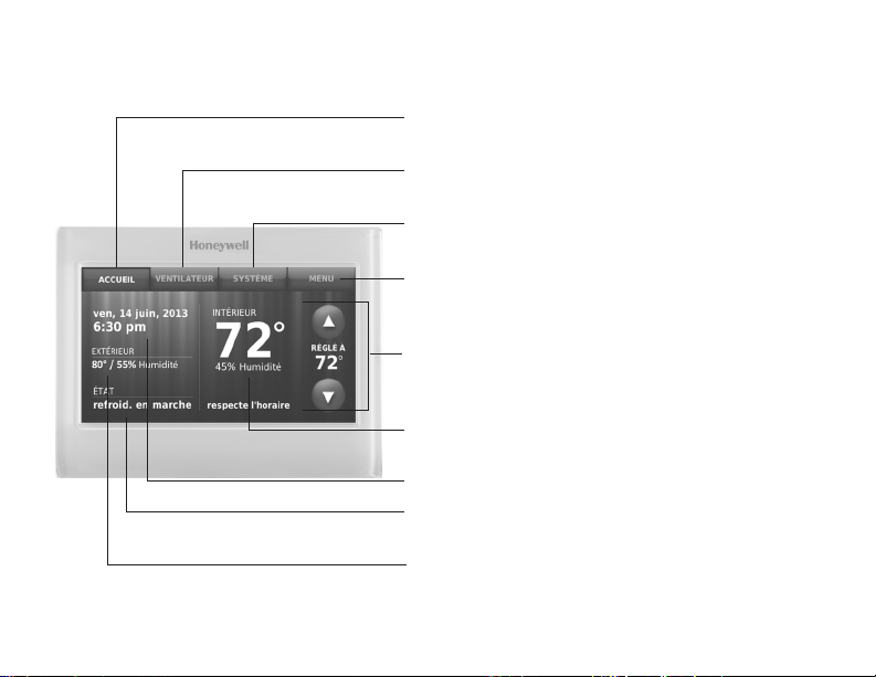
Référence rapide : utilisation résidentielle
ACCUEIL. Touchez pour afficher l’écran
Accueil.
VENTILATEUR. Sélectionnez le mode du
ventilateur.
SYSTÈME. Sélectionnez le mode du système
(chauffage/refroidissement).
MENU. Touchez pour afficher les options.
Commencez ici pour configurer un
programme.
Programme en cours. Modifiez le réglage
de la température et sélectionnez le maintien
provisoire ou permanent.
Conditions intérieures. Affiche la
température et l’humidité intérieures.
Heure et date actuelles.
Statut en cours. Affiche le mode du système
(chauffage/refroidissement).
Conditions extérieures. La température
et l’humidité extérieures s’affichent après
l’enregistrement.
69-2809EF—03 4
Page 87

Référence rapide : utilisation commerciale
ACCUEIL. Touchez pour afficher l’écran Accueil.
VENTILATEUR. Sélectionnez le mode du
ventilateur.
SYSTÈME. Sélectionnez le mode du système
(chauffage/refroidissement).
MENU. Touchez pour afficher les options.
Commencez ici pour configurer un programme.
Emplacement du thermostat. Identifie rapidement
le thermostat contrôlant une zone spécifique.
Programme en cours. Touchez une flèche pour
modifier le réglage de température et régler le
maintien provisoire.
Dérivation. Touchez pour déroger provisoirement au
programme.
Conditions intérieures. Affiche la température et
l’humidité intérieures.
Heure et date actuelles.
Statut en cours. Affiche le mode du système
(chauffage/refroidissement).
Conditions extérieures. La température et l’humidité
5 69-2809EF—03
extérieures s’affichent après l’enregistrement.
Page 88

Configuration de votre thermostat
La configuration de votre thermostat programmable à écran tactile couleur Wi-Fi est
facile. Il est préprogrammé et prêt à fonctionner dès qu’il est installé et enregistré.
Installez votre thermostat.
1
Connectez-le au réseau sans fil de votre domicile.
2
Enregistrez-vous en ligne pour bénéficier de l’accès à distance.
3
Avant de commencer, vous désirerez peut-être visionner une courte
vidéo d’installation. Utilisez le QR Code
ce guide ou rendez-vous à l’adresse wifithermostat.com./support.
69-2809EF—03 6
®
figurant sur la couverture de
Page 89

Installation de votre thermostat
Vous aurez besoin des outils suivants pour l’installation de ce thermostat :
• Un tournevis cruciforme n° 2
• Un stylo
• Un crayon
• Un niveau (optionnel)
• Une perceuse et des mèches
1 Coupez l’alimentation sur
votre système de chauffage/
refroidissement.
Important! Pour protéger votre
équipement, coupez l’alimentation
de votre système de chauffage/
refroidissement au niveau de
la boîte des disjoncteurs ou du
commutateur du système.
7 69-2809EF—03
(3/16 po pour une cloison
sèche, 7/32 po pour du plâtre)
(optionnels)
• Un marteau (optionnel)
• Du ruban électrique (optionnel)
ou
Boîte des
disjoncteurs
Interrupteur
d’alimentation
du système
de chauffage/
refroidissement
Page 90

Installation de votre thermostat
2 Retirez la plaque de l’ancien
thermostat et laissez les fils connectés.
2a Prenez une photo des
connexions de câblage pour
référence ultérieure.
2b Si aucun fil n’est connecté à
la borne C ou si aucune borne
C n’est présente sur l’ancien
thermostat, visionnez les vidéos
expliquant les autres méthodes
de câblage à
wifithermostat.com/videos
Important! Le fil C est requis et
représente la source d’alimentation
du thermostat. Sans fil C, votre
thermostat ne se mettra pas en
marche.
69-2809EF—03 8
Remarque : Vous aurez
besoin d’une photo des
connexions de câblage
pour câbler le nouveau
thermostat.
C
Désignation
des bornes
Si vous possédez un thermostat
plus ancien à tube de mercure
scellé, allez à la page 2 pour les
instructions de mise au rebut
correctes.
Page 91

Installation de votre thermostat
3 Étiquetez les fils.
Utilisez les étiquettes
autocollantes fournies pour
étiqueter chaque fil lorsque vous
le déconnectez. Étiquetez les fils
conformément aux désignations
de bornes de l’ancien thermostat
et non pas en fonction des
couleurs des fils.
Remarque : Si aucune
étiquette ne correspond à une
désignation de borne, notez
la lettre appropriée sur une
étiquette collante vierge.
4 Retirez la plaque murale.
Retirez l’ancienne plaque murale
du mur après avoir étiqueté et
déconnecté tous les fils.
Remarque : Enroulez les fils autour
d’un crayon pour éviter qu’ils ne
C
C
tombent dans l’ouverture du mur.
9 69-2809EF—03
Étiquette
autocollante
Étiquettes
vierges
Désignation
des bornes
Page 92

Installation de votre thermostat
5 Montez la plaque murale du
thermostat Wi-Fi.
Montez votre nouvelle plaque
murale à l’aide des vis et
chevilles fournies avec le
thermostat.
Au besoin :
Percez des trous de 3/16 po
pour les cloisons sèches.
Percez des trous de 7/32 po
pour le plâtre.
Remarque : Vous pourrez
peut-être utiliser les ancres
murales déjà installées. Tenez
la plaque murale sur les ancres
déjà installées pour vérifier
l’alignement.
69-2809EF—03 10
LEVEL
HERE
C
K
Rc
R
R
C
G
Plaque murale
WO/B
Y
G
W2Aux/E
Y2
L
Y
W
MCR34499
Page 93

Installation de votre thermostat
Important! Le fonctionnement du thermostat Wi-Fi requiert l’utilisation d’un fil C. Le fil
C, ou neutre, amène l’alimentation 24 V c.a. au thermostat. De nombreux thermostats
mécaniques ou à piles plus anciens n’ont pas besoin d’un fil C. Si vous ne disposez
pas d’un fil C, essayez :
• de rechercher un fil inutilisé enfoncé dans le mur. Connectez ce fil au fil C
et vérifiez s’il est connecté au fil C 24 V c.a. de votre système de chauffage/
refroidissement. Consultez la section vidéo à l’adresse wifithermostat.com
Remarque : Les systèmes de chauffage/refroidissement n’indiquent pas tous le fil C
commun de 24 V c.a. Consultez le manuel du système ou le fabricant pour avoir quelle
borne est la borne commune de 24 V c.a.
Visionnez les vidéos expliquant les autres méthodes de câblage à l’adresse
wifithermostat.com/videos
Câblage
Pour les systèmes de chauffage/refroidissement conventionnels (gaz naturel, appareil
de chauffage à mazout ou électrique, climatiseur), voir page 12. Voir le « Glossaire » à
la page 73 pour les définitions.
Pour les systèmes à thermopompe, consultez la page 14. Voir le « Glossaire » à la
page 73 pour les définitions.
11 69-2809EF—03
Page 94

Installation de votre thermostat
Câblage (système conventionnel)
6A Branchez le thermostat Wi-Fi sur votre
système conventionnel.
a En commençant par le fil C, faites
correspondre l’étiquette autocollante sur
le fil à l’étiquette de la borne.
Vous devez avoir un fil C. Consultez la
page 11.
b
Redressez le fil et faites-le glisser
délicatement dans l’orifice de la borne
jusqu’à ce qu’il s’enclenche en position.
(Si un fil doit être retiré, utilisez l’extrémité
d’un stylo pour appuyer sur le dispositif
de libération et retirez le fil.)
Remarque: Consultez la photo de câblage
prise à l’étape 2.
Conseil : Pour faciliter l’insertion du fil,
utilisez l’extrémité d’un stylo pour appuyer
sur le dispositif de libération de la borne.
69-2809EF—03 12
Remarque : Le câblage de
votre application spécifique peut
être différent du câblage illustré
ci-après.
Libération de la borne
Rc
C
K
R
C
R
EXEMPLE DE CÂBLAGE
W
Y
G
Le vôtre peut être différent
WO/B
Y
G
W2-
Aux/E
Y2
L
Retirez la boucle de raccordement
SEULEMENT si les fils R et Rc
sont tous les deux présents.
Les étiquettes ne correspondent
pas? Reportez-vous au code
de câblage alternatif aux pages
16-17.
Page 95

Installation de votre thermostat
Câblage (système conventionnel suite)
c Dans l’image à droite, cochez la case
à côté de chaque connexion. Vous
utiliserez cette liste de vérification à
l’étape 9.
d Vérifiez que le fil est bien attaché en
tirant délicatement dessus.
e Répétez les étapes a–d pour tous les
autres fils.
f Repoussez tout excédent de fil dans
l’ouverture murale une fois tous les fils
installés.
g Passez à la page 20.
13 69-2809EF—03
Les étiquettes ne correspondent
pas? Reportez-vous au code de
câblage alternatif aux pages 16-17.
Important!
Cochez la case pour chaque
fil que vous connecter.
Vous aurez besoin de cette
information à l’étape 9.
C
K
Rc
R
W-O/B
Y
G
W2Y2
L
Aux/E
Page 96

Installation de votre thermostat
Câblage (système à thermopompe)
6B Branchez le thermostat Wi-Fi à votre
thermopompe.
a En commençant par le fil C, faites
correspondre l’étiquette autocollante sur
le fil à l’étiquette de la borne.
Vous devez avoir un fil C. Consultez la
page 11.
b Faites délicatement glisser le fil dans
l’orifice de la borne jusqu’à ce qu’il
s’enclenche en position. (Si un fil doit
être retiré, utilisez l’extrémité d’un stylo
pour appuyer sur le dispositif de
libération et retirez le fil.)
Remarque : Consultez la photo de câblage
prise à l’étape 2.
Conseil : Pour faciliter l’insertion du fil,
utilisez l’extrémité d’un stylo pour appuyer
sur le dispositif de libération de la borne.
69-2809EF—03 14
Remarque : Le câblage de
votre application spécifique peut
être différent du câblage illustré
ci-après.
Disposition de libération de la borne
O
Y
G
AUX
EXEMPLE DE CÂBLAGE
Le vôtre peut être différent
WO/B
Y
G
W2-
Aux/E
Y2
L
Rc
C
K
R
C
R
Retirez la boucle de raccordement
SEULEMENT si les fils R et Rc
sont tous les deux présents.
Les étiquettes ne correspondent
pas? Reportez-vous au code de
câblage alternatif aux pages 18-19.
Page 97

Installation de votre thermostat
Câblage (système à thermopompe suite)
c Dans l’image à droite, cochez la case
à côté de chaque connexion. Vous
utiliserez cette liste de vérification à
l’étape 9.
d Vérifiez que le fil est bien attaché en
tirant délicatement dessus.
e Répétez les étapes a–d pour tous les
autres fils.
Remarque : Si l’ancien thermostat a
des fils séparés sur Aux et E, utilisez un
serre-fil pour attacher les deux fils à un
fil séparé. Faites glisser ce troisième fil
dans la borne W2-Aux/E.
f Poussez tout excédent de fil dans
l’ouverture mural une fois tous les fils
installés.
g Passez à la page 20.
15 69-2809EF—03
Important!
Cochez la case pour chaque
fil que vous connecter.
Vous aurez besoin de cette
information à l’étape 9.
C
K
Rc
R
Les étiquettes ne correspondent
pas? Reportez-vous au code de
câblage alternatif aux pages 18-19.
W-O/B
Y
G
W2Y2
L
Aux/E
Page 98

Installation de votre thermostat
Câblage alternatif (système conventionnel)
Utilisez ceci si vos étiquettes
de fils ne correspondent pas
aux références de bornes.
Remarque : Vous devez
avoir un fil C ou un fil
équivalent. Consultez la
page 11.
69-2809EF—03 16
C
1
K
Rc
2
R
2
Reportez-vous aux codes
C
B
X
C1
Rc
R
R
V
4
RH
W
W1
Y
G
W2
Y2
WO/B
Y
G
W2-
Aux/E
Y2
L
1
– 2 de la page 17.
Page 99

Installation de votre thermostat
Code de câblage alternatif (système conventionnel)
N’utilisez pas la borne K. Pour utilisation ultérieure.
1
• SiunfilR et Rc sont présents, débranchez la boucle de raccordement en tirant
2
sur la boucle.
• SivotreancienthermostatadesfilsR et RH, branchez le fil R à la borne Rc, le
fil RH à la borne R, et débranchez la boucle de raccordement.
17 69-2809EF—03
Page 100

Installation de votre thermostat
Câblage alternatif (système à thermopompe)
Utilisez ceci si vos étiquettes
de fils ne correspondent pas
aux références de bornes.
Remarque : Vous devez
avoir un fil C ou un fil
équivalent. Consultez la
page 11.
69-2809EF—03 18
C
1
K
2
Rc
3
R
2
Reportez-vous aux codes
C
B
X
Rc
R
R
VR
V
O
B
Y
G
AUX
W W1
X X2
W2
Y2
L
F
1
– 7 de la page 19.
WO/B
Y
G
W2-
Aux/E
Y2
L
4
5
6
7
 Loading...