

Page 1

User Guide
Wi-Fi Programmable
Thermostat
RTH6500WF Wi-Fi Series
Page 2

In the box you will find
• Thermostat
• Wallplate (attached to thermostat)
• Screws and anchors
• Quick Start Guide
• Thermostat ID Card
• Wire labels
• User Guide
• Quick Reference Card
69-2718ES—03 ii
Page 3

Welcome
Congratulations on your purchase of a
Honeywell Wi-Fi programmable thermostat.
When registered to Honeywell’s Total Connect
Comfort Solutions, you can remotely monitor
and control the heating and cooling system
in your home or business—you can stay
connected to your comfort system wherever
you go.
Honeywell’s Total Connect Comfort is the
perfect solution if you travel frequently, own
a vacation home, a business or manage an
Investment property or if you are simply looking
for peace of mind.
Page 4

This thermostat works with common 24 volt systems such as forced air, hydronic,
heat pump, oil, gas, and electric. It will not work with millivolt systems, such as a gas
fireplace, or with 120/240 volt systems such as baseboard electric heat.
MERCURY NOTICE: Do not place your old thermostat in the trash if it contains
mercury in a sealed tube. Contact the Thermostat Recycling Corporation at www.
thermostat-recycle.org or 1-800-238-8192 for information on how and where to
properly and safely dispose of your old thermostat.
NOTICE: To avoid possible compressor damage, do not run air conditioner if the
outside temperature drops below 50°F (10°C).
Need help?
Visit wifithermostat.com or call 1-855-733-5465 for assistance before returning the
thermostat to the store.
69-2718ES—03 2
Page 5

Table of contents
About your new thermostat
Controls and Home screen
quick reference ............................................5
Preset energy-saving schedules ................. 6
Installation
Installing your thermostat ............................ 8
Connecting to your Wi-Fi network .............26
Registering your thermostat online ........... 31
Operation
Setting the clock ........................................ 36
Setting the fan ........................................... 37
Selecting system mode ............................. 38
Adjusting program schedules .................... 39
Overriding schedules temporarily .............40
Overriding schedules permanently ........... 41
69-2718ES—03 3
Unregistering thermostat........................... 42
Disconnecting Wi-Fi .................................. 43
Special features ........................................45
Setting functions and options ....................48
Appendices
Frequently asked questions ......................55
Troubleshooting .........................................61
Limited warranty ........................................ 67
Page 6

Features of your Wi-Fi thermostat
With your new thermostat, you can:
• Connect to the Internet to monitor and control your heating/cooling system
• View and change your heating/cooling system settings
• View and set temperature and schedules
• Receive alerts via email and get automatic upgrades
Your new thermostat provides:
• Smart Response Technology
• Compressor protection
• Heat/cool auto changeover
69-2718ES—03 4
Page 7
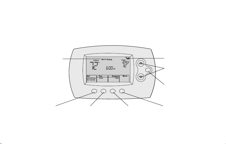
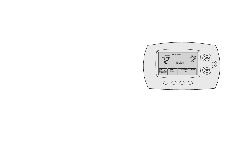
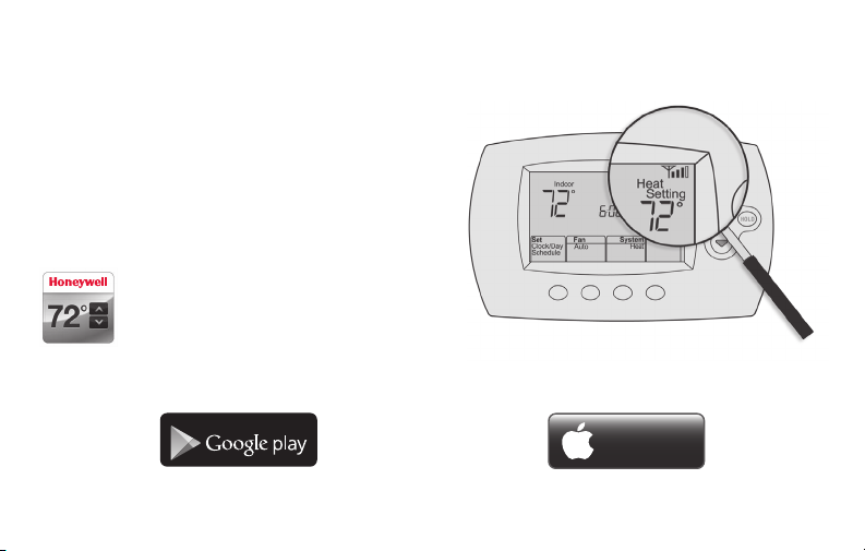
Controls and home screen quick reference
M31586
Once your Wi-Fi thermostat is installed, it will display the home screen. Portions of this
display will change depending on how you are viewing it.
Set up messages
describe steps in the
Wi-Fi set up process
Set clock, day,
or schedule
Select fan
settings
HOLD
Select system
mode
Wi-Fi status
Temperature adjustment
buttons
Permanent override
button
Additional
settings
The screen lights when you press any button. It stays lit for 8 seconds after you complete
changes.
5 69-2718ES—03
Page 8
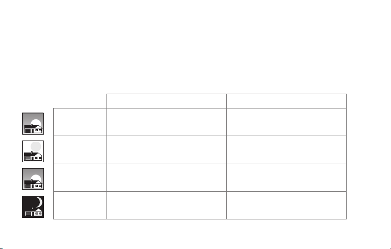
Preset energy-saving schedules
This thermostat is pre-set with energy-saving program settings for four time periods.
Using the default settings can reduce your heating/cooling expenses if used as directed.
Savings may vary depending on geographic region and usage. To change the settings,
see pages 39–41.
Default Heat Settings Default Cool Settings
WAKE
6:00 am
LEAVE
8:00 am
RETURN
6:00 pm
SLEEP
10:00 pm
69-2718ES—03 6
70
62
70
62
°
°
°
°
78
85
78
82
°
°
°
°
Page 9

Setting up your thermostat
Setting up your Wi-Fi programmable thermostat is easy. It is preprogrammed and ready to
go as soon as it is installed and registered.
Install your thermostat.
1
Connect your home Wi-Fi network.
2
Register online for remote access.
3
Before you begin, you may want to watch a brief installation video. Use
the QR Code® at the front of this guide, or go to wifithermostat.com/support
7 69-2718ES—03
Page 10
Installing your thermostat
You might need the following tools to install this thermostat:
• No. 2 Phillips screwdriver
• Small pocket screwdriver
• Pencil
• Level (optional)
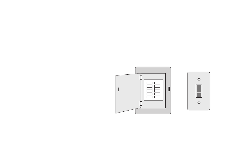
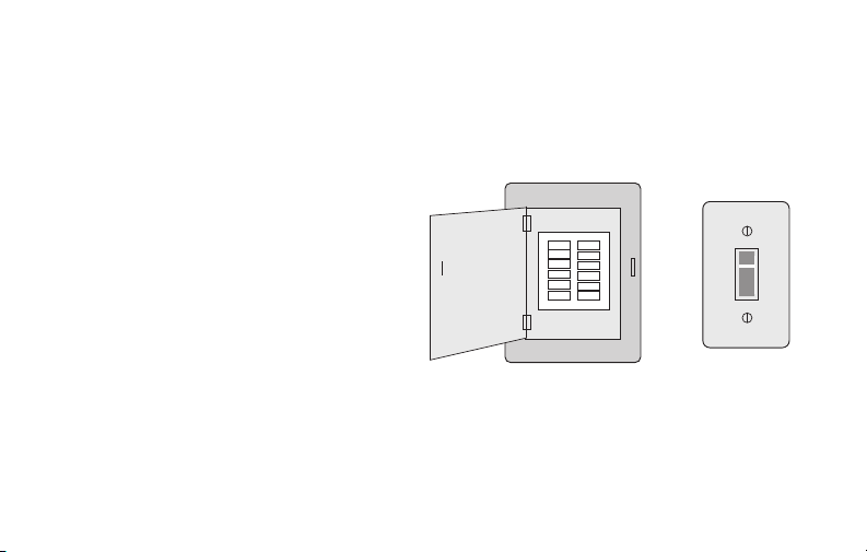
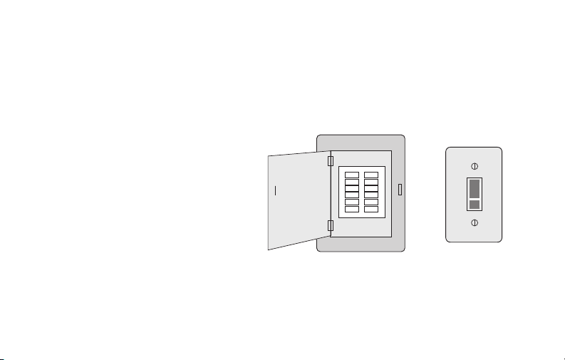
1 Switch OFF power to your
heating/cooling system.
Important! To protect your equipment,
switch OFF the power to your heating/
cooling system at the breaker box or
the system switch.
69-2718ES—03 8
• Drill and bits (3/16” for drywall,
7/32” for plaster) (optional)
• Hammer (optional)
• Electrical tape (optional)
Circuit breaker
box
or
Heating/cooling
system power
switch
Page 11
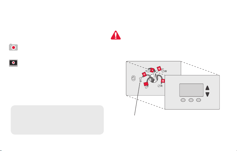
Installing your thermostat
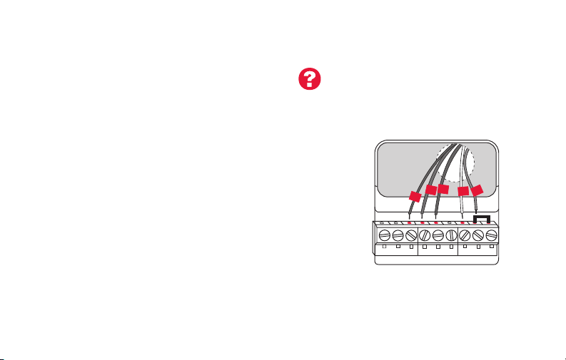
2 Remove old thermostat faceplate
and leave wires connected.
2a Take a picture of the wire
If you have an older thermostat with a
sealed mercury tube, turn to page 2
for proper disposal instructions.
connections for later reference.
2b If no wire is connected to a
terminal labeled C or no C
terminal exists on the old
thermostat, view the Alternate
Wiring videos at
C
C
wifithermostat.com/videos
Important! C wire is required and
is the primary power source for
your thermostat. Without a C wire,
your thermostat will not power up.
9 69-2718ES—03
Terminal
designation
Page 12
Installing your thermostat
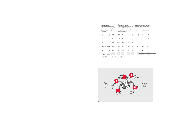
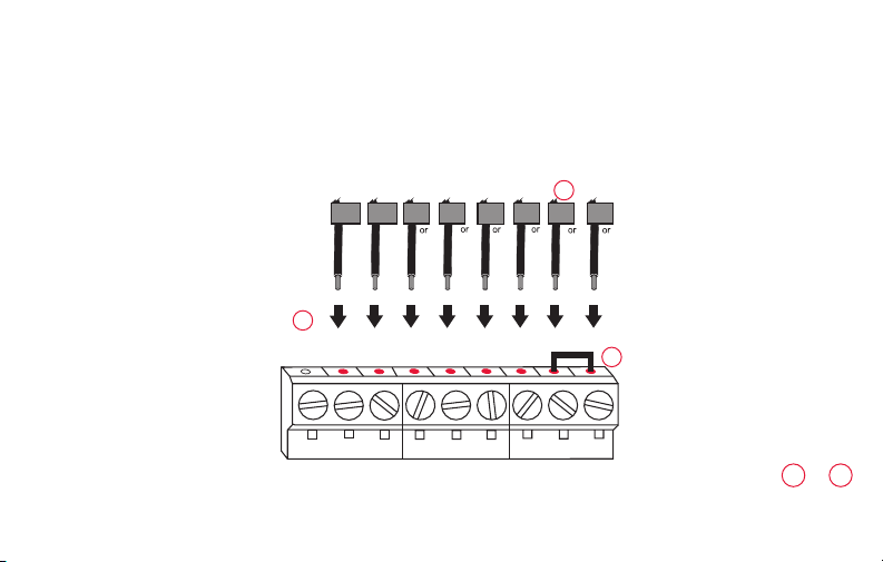
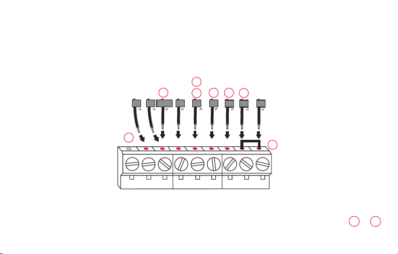
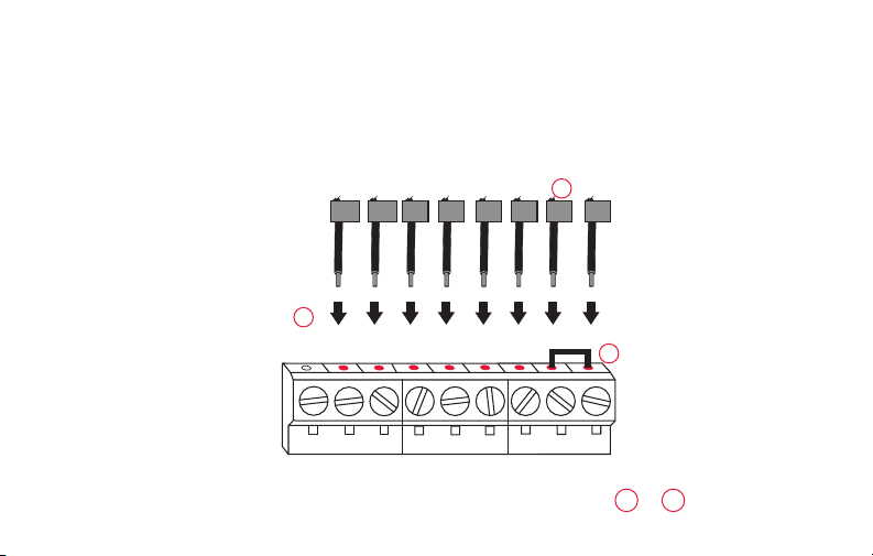
3 Label wires.
Do not label by wire color. Use
the supplied sticky tags to label
each wire as you disconnect it.
Label wires according to the old
thermostat terminal designations,
not by wire color.
Note: If no tag matches a wire
terminal label, write the terminal
label on a blank tag.
4 Remove wallplate.
Remove the old wallplate from
the wall after all wires have been
labeled and disconnected.
69-2718ES—03 10
Sticky tags
Blank sticky
tags
C
C
Terminal
designation
Page 13
Installing your thermostat
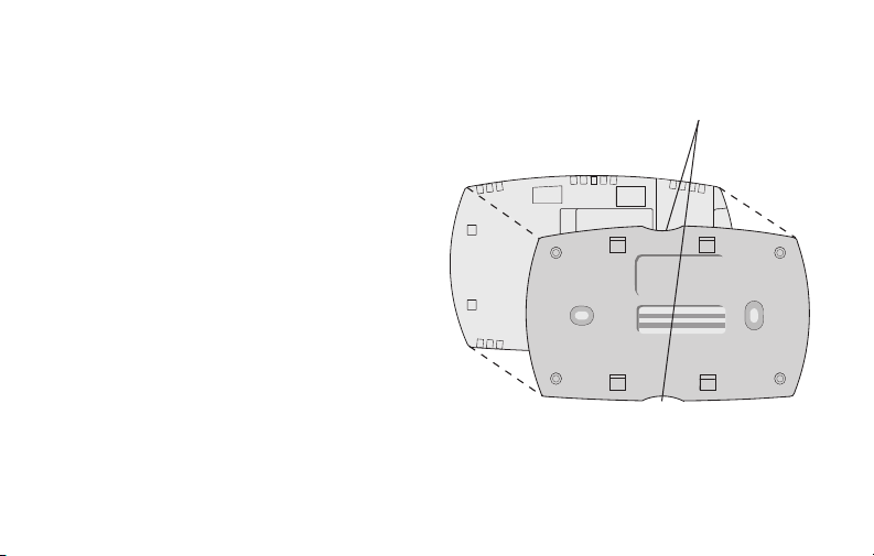
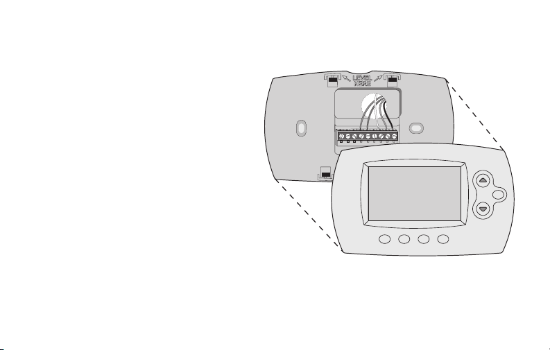
5 Separate Wi-Fi thermostat and its
wallplate.
On your new thermostat, grasp the
Thermostat
Finger holds
finger holds on the top and bottom of
the wallplate with one hand and the
thermostat (front) with the other hand.
PULL HERE
TO REMOVE
Pull pieces apart.
PULL HERE
TO REMOVE
M33856
Wallplate (back view)
11 69-2718ES—03
Page 14
Installing your thermostat
MCR33857
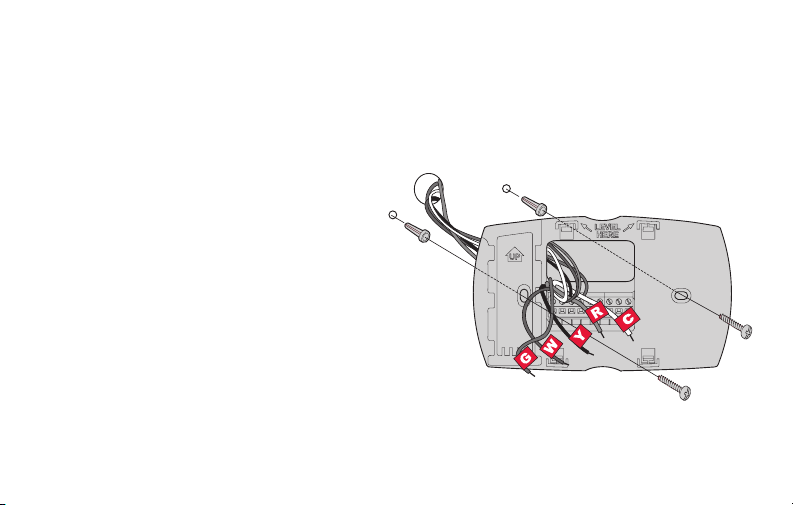
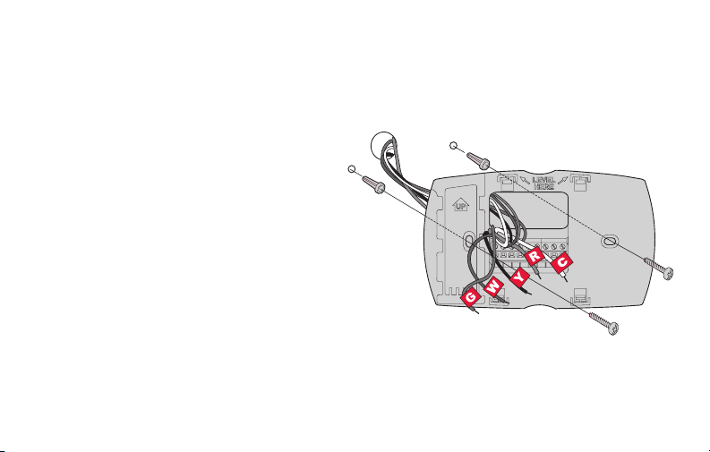
6 Mount wallplate for Wi-Fi thermostat.
Mount your new wallplate using screws and anchors
included with the thermostat.
If necessary:
Drill 3/16-in holes for drywall.
Drill 7/32-in holes for plaster.
Note: You may be able to use your existing
wall anchors. Hold the wallplate up to the
existing anchors to check for alignment.
Wallplate
69-2718ES—03 12
Page 15

Installing your thermostat
Important! The Wi-Fi thermostat requires a C wire to operate. The C, or common, wire
brings 24 VAC power to the thermostat. Many older mechanical or battery operated
thermostats do not require a C wire. If you don’t have a C wire, try:
• Looking for an unused wire that is pushed into the wall. Connect that wire to C and
check that it is connected to the 24 VAC common at your heating/cooling system.
Note: Not all heating/cooling systems label the 24 VAC common C. Check your system
manual or contact the manufacturer to find out which terminal is the 24 VAC common.
View the Alternate Wiring videos at wifithermostat.com/videos
Wiring
For conventional heating/cooling systems (natural gas, oil or electric furnace, air
conditioner), see page 14. See “Glossary” on page 64 for further definition.
For a heat pump system, see page 15. See “Glossary” on page 64 for further
definition.
13 69-2718ES—03
Page 16
Installing your thermostat
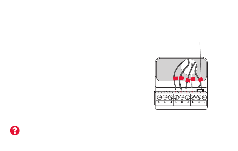
Wiring (conventional system)
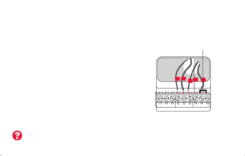
7A Wire the Wi-Fi thermostat to your conventional system.
a Starting with the C Wire, match the sticky tag on the
wire to the terminal labels.
You must have a C wire. See page 13.
b Loosen screw, insert wire on inside edge
of terminal, then tighten screw.
c Verify wire is firmly secured by gently
pulling on wire.
d Repeat steps a–c for all other wires.
e Push any excess wire back into the wall
opening after all wires are installed.
f Continue to page 20.
Labels don’t match? See alternate
wiring key on pages 16–17.
69-2718ES—03 14
Remove metal jumper
only if you have both
R and RC wires
W
G
Y
R
C
C
G W
Y2
W2
AUX/E
L
G O/B
YR RCK
CONVENTIONAL
C
YRRCK
HEAT PUMP
Note: The wiring for your
application might be different
from the wiring shown above.
Page 17
Installing your thermostat
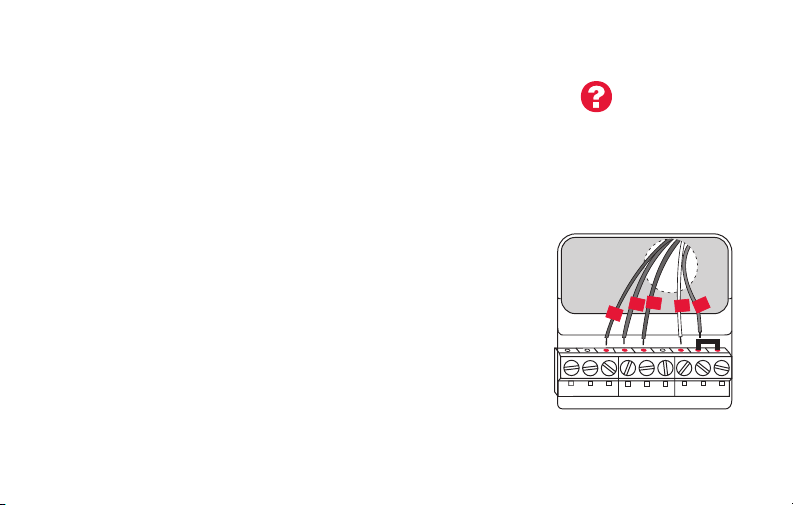
Wiring (heat pump system only)
7B Wire Wi-Fi thermostat to your heat pump.
Labels don’t match? See alternate
wiring key on pages 18–19.
a Starting with the C Wire, match the sticky tag on the wire to the terminal labels.
You must have a C wire. See page 13.
b Loosen screw, insert wire on inside edge
of terminal, then tighten screw.
c Verify wire is firmly secured by gently
pulling on wire.
O
G
Aux
R
Y
d Repeat steps a–c for all other wires.
e Push any excess wire back into the wall
opening after all wires are installed.
f
Continue to page 20.
AUX/E
L
G O/B
C
YRRCK
HEAT PUMP
Note: If old thermostat has separate wires on AUX and
E, place both wires into the E/AUX terminal.
If old thermostat has wire on AUX with a jumper to E,
place wire on E/AUX terminal. No jumper is required.
15 69-2718ES—03
Note: The wiring for your
application might be different
from the wiring shown above.
Page 18
Installing your thermostat
MCR33885
CONVENTIONAL
Alternate wiring (conventional system)
Use this if your wire labels don’t match the terminal labels.
Y2
Note: You must have
W2
a C wire or equivalent.
See page 13.
1
W2
G W
Y2
K
69-2718ES—03 16
W1F
H
C
X
B
C1
C
YRRC
2
RYWG
RC
R
RHY1
4M
V
3
See key to 1 – 3
on page 17.
Page 19

Installing your thermostat
Alternate wiring key (conventional system)
Do not use K terminal. For future use.
1
If your old thermostat had both R and RH wires, remove metal jumper.
2
Connect the R wire to the RC terminal, and the RH wire to the R terminal.
Remove metal jumper connecting R and RC only if you must connect both
3
R and RC.
17 69-2718ES—03
Page 20
Installing your thermostat
MCR33886
T PUMP
Alternate wiring (heat pump system only)
Use this if your wire labels don’t match the terminal labels.
3
Note: You must have
a C wire or equivalent.
See page 13.
EAUX
L
XW FH
F
X2
1
2
4
OG
W1
W2
5
4
C
B
6
RY
X
B
RC
R
VY1
VRM
7
AUX/E
G O/B
L
69-2718ES—03 18
C
YRRCK
HEA
See key to 1 – 7
on page 19.
Page 21

Installing your thermostat
Alternate wiring key (heat pump system only)
Do not use K terminal. For future use.
1
If old thermostat has separate wires on AUX and E, place both wires into the E /AUX terminal. If
2
old thermostat has wire on AUX with a jumper to E, place wire on E /AUX terminal. No jumper is
required.
If your old thermostat had an O wire and not a B wire, attach the O wire to the O/B terminal.
3
If your old thermostat had separate O and B wires, attach the B wire to the C terminal. If
4
another wire is attached to the C terminal, check wifithermostat.com for help. Attach the O wire
to the O/B terminal.
If your old thermostat had separate Y1, W1 and W2 wires, check wifithermostat.com for help.
5
If your old thermostat had both V and VR wires, check wifithermostat.com for help.
6
Leave metal jumper between R and RC terminals in place.
7
19 69-2718ES—03
Page 22
Installing your thermostat
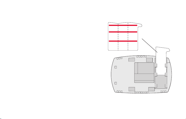
8 Insert quick reference card.
Fold quick reference card
along score lines, and slide
it into the slot on the back of
the thermostat.
69-2718ES—03 20
Quick
reference
card
MCR33916
Back of thermostat
Page 23
Installing your thermostat
M33860
9 Attach thermostat to wallplate.
Align the thermostat to the wallplate
and then snap into place.
HOLD
21 69-2718ES—03
Page 24
Installing your thermostat
10 Switch heating/cooling system ON.
Important!
10a Verify that the C wire is
connected at the thermostat
and at the heating/cooling
system.
10b Make sure the heating/
cooling system door is firmly
secured.
10c Switch power back ON for
your heating/cooling system
at the breaker box or its
power switch.
69-2718ES—03 22
Circuit breaker
box
or
Heating/cooling
system power
switch
Page 25
Installing your thermostat
MCR33909
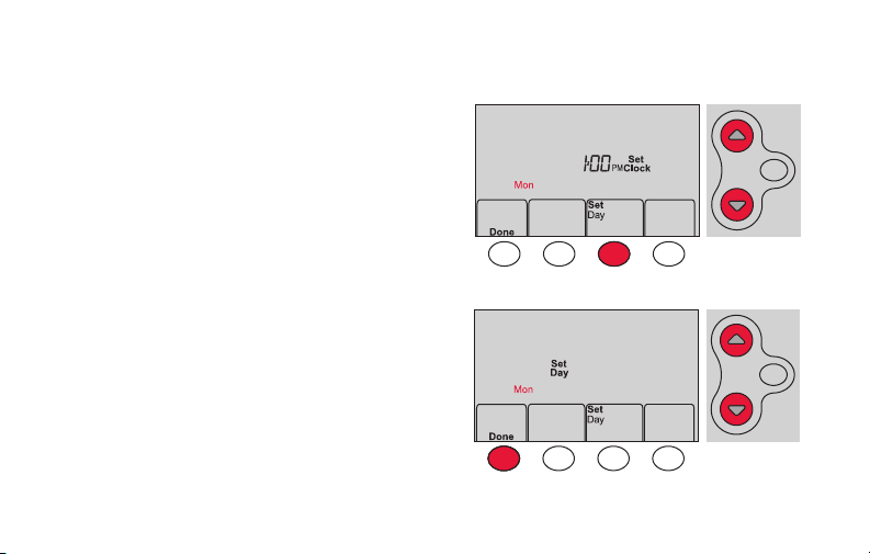
11 Set clock to current day and time.
11a Press s or t to set clock.
11b Press Set Day.
11c Press s or t to select the
day of week.
11d Press Done to save.
(Press and hold a st button to
quickly change a setting.)
HOLD
MCR33908
HOLD
23 69-2718ES—03
Page 26
Installing your thermostat
12 Determine your heating/cooling system type.
Important! Heating/cooling system type must be set so that your
thermostat operates properly and does not damage your system.
12a If your system type is conventional single stage (natural gas-powered single
stage with a/c), continue to “Connecting to your Wi-Fi network” on page 26.
12b If your system is:
• Conventional multistage heat and cool
• Any type of heat pump
• Hydronic
• Other
You MUST change the system type by setting system function 1. See page 48 to
match your thermostat to your system type.
69-2718ES—03 24
If you are not sure of your
heating/cooling system type
or have other questions, go
to wifithermostat.com/support
Page 27

Installing your thermostat
MCR33880
Congratulations! Your thermostat is operational.
13 Test your thermostat
13a Press the
heating or cooling and begin operation.
13b For remote access to your thermostat,
continue to
network” on page 26.
25 69-2718ES—03
System
button to change to
“Connecting to your Wi-Fi
Heating/cooling system not turning
on? Refer to page 62 or FAQ at
wifithermostat.com/support
Page 28

Connecting to your Wi-Fi network
To complete this process, you must have a wireless device connected to your home
wireless network. Any of these device types will work:
• Tablet (recommended)
• Laptop (recommended)
• Smartphone
If you get stuck... at any point in this procedure, restart the thermostat by
removing the thermostat from the wallplate, wait for 10 seconds, and snap it back
onto the wallplate. Go to Step 1 in this procedure, starting on page 27.
View the Wi-Fi Enrollment video at wifithermostat.com/videos
69-2718ES—03 26
Page 29
Connecting to your Wi-Fi network
M33852
1 Connect to your thermostat.
1a Make sure the thermostat displays
Wi-Fi Setup.
1b On the wireless device (laptop, tablet,
smartphone), view the list of available Wi-Fi
networks.
1c Connect to the network called
NewThermostat_123456 (the number will
vary).
Note: If you are asked to specify a home, public, or
office network, select Home Network.
27 69-2718ES—03
HOLD
Page 30

Connecting to your Wi-Fi network
M31567
2 Join your home network.
2a Open your web browser to access the
Thermostat Wi-Fi Setup page. The browser
should automatically direct you to the correct
page; if it does not, go to http://192.168.1.1
2b Find the name of your home network on this
page and select it.
Note: Some routers have enhanced features such as
guest networks; use your home network.
2c Complete the instructions for joining your Wi-Fi
network and click on the Connect button.
(Depending on your network setup, you may see
an instruction such as Enter Password for your home network.)
Note: If you did not correctly connect to the thermostat, you may see
your home router page. If so, return to Step 1.
69-2718ES—03 28
Page 31

Connecting to your Wi-Fi network
Note: If your Wi-Fi network does not appear in the list on the Thermostat Wi-Fi Setup
page:
• Try performing a network rescan by pressing the Rescan button. This is helpful in
areas with a lot of networks.
• If you are connecting to a hidden network, then enter the network SSID in the
textbox, select the encryption type from the drop down menu, and click on the
Add button. This manually adds the network to the top of the list. Click on the new
network in the list and enter the password if necessary. Click on Connect to join the
network.
29 69-2718ES—03
Page 32

Connecting to your Wi-Fi network
3 Make sure your thermostat is connected.
While the connection is in process, your thermostat
will flash Wait for up to 3 minutes. When the
connection is complete, the display will show Wi-Fi
Setup Connection Success. The Wi-Fi signal strength
will appear in the top-right corner.
After about 60 seconds, the home screen will appear
and Register at Total Connect will flash until registration
is complete.
If you don’t see these messages, see page 26.
To register online for remote access to your thermostat
continue on page 31.
Note: If the thermostat displays Connection Failure or continues to display
Wi-Fi Setup, confirm you correctly entered your home network password in
step 2. If correct, refer to the FAQ at wifithermostat.com/support
69-2718ES—03 30
Page 33
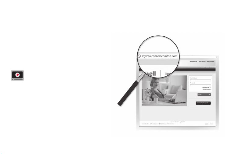
Registering your thermostat online
To view and set your Wi-Fi thermostat
remotely, you must have a Total Connect
Comfort account. Use the following steps.
1 Open the Total Connect Comfort web site.
Go to mytotalconnectcomfort.com
View the Wi-Fi Thermostat Registration
video at wifithermostat.com/videos
M31570
31 69-2718ES—03
Page 34

Registering your thermostat online
2 Login or create an account.
If you have an account,
click Login
– or –
click Create An Account
2a Follow the instructions on the screen.
2b Check your email for an activation
message from My Total Connect Comfort.
This may take several minutes.
Note: If you do not receive a response, check
your junk mailbox or use an alternate e-mail
address.
2c Follow activation instructions in the
email.
2d Log in.
69-2718ES—03 32
.
M31571
Page 35
Registering your thermostat online
Printed in U.S.A.
69-2723EFS-01
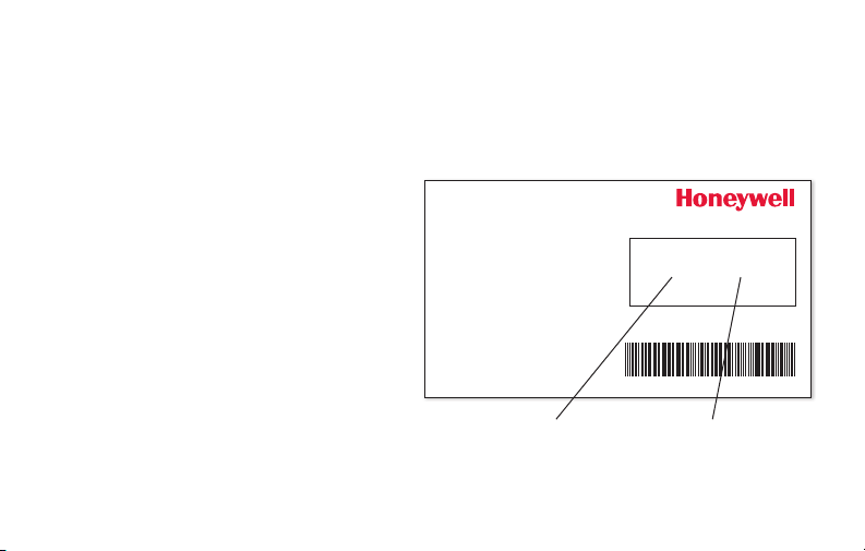
3 Register your Wi-Fi thermostat.
After you are logged in to your Total Connect Comfort account,
register your thermostat.
3a Follow the instructions on
the screen. After adding your
thermostat location, you must enter
the thermostat’s unique identifiers:
• MAC ID
• MAC CRC
Note: These IDs are listed on the
Thermostat ID Card included in the
thermostat package. The IDs are
not case sensitive.
33 69-2718ES—03
Thermostat ID Card
Use the MAC ID and CRC ID to register
this product at mytotalconnectcomfort.com
Carte d’identification de thermostat
Utilisez l’identication MAC et l’identication CRC pour
enregistrer ce produit à mytotalconnectcomfort.com
Tarjeta de identificación del termostato
Utilice la identicación MAC y la identicación CRC para
inscribir este producto en mytotalconnectcomfort.com
® U.S. Registered Trademark.
© 2012 Honeywell International Inc.
69-2723EFS—01 M.S. 04-12
MAC ID MAC CRC
HONEYWELL MODEL:
MAC ID: MAC CRC:
Page 36
Registering your thermostat online
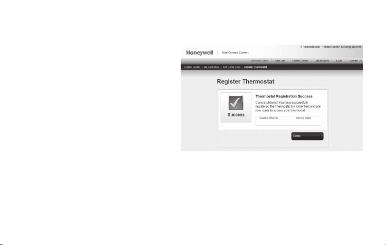
3b When the thermostat is
successfully registered,
the Total Connect Comfort
registration screen will
display a SUCCESS
message.
In the thermostat display, you
will see Setup Complete for
about 90 seconds.
69-2718ES—03 34
Page 37
Registering your thermostat online
3c Also notice that your thermostat displays
its signal strength.
Congratulations! You’re done.
You can now control your thermostat from
anywhere through your tablet, laptop, or
smartphone
Total Connect Comfort free app is
available for Apple® iPhone®, iPad® and
iPod touch® devices at iTunes® or at
Google Play® for all Android™ devices.
GET IT ON
Download on
iTunes
35 69-2718ES—03
Page 38
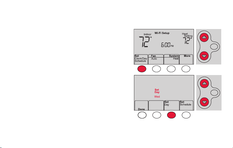
Setting the time and day
MCR33855
1 Press Set Clock/Day/Schedule, then press s
or t to set clock.
2 Press Set Day, then press s or t to select
the day of week.
3 Press Done to save.
Note: If the Set Clock/Day/Schedule option is not
displayed, press Done.
Note: If the display flashes Set Clock, the
thermostat will follow your settings for the
Monday “Wake” time period until you reset the
time and day.
69-2718ES—03 36
HOLD
HOLD
Page 39

Setting the fan
MCR33895
Press Fan to select On or Auto (toggle to
re-select).
Auto
: Fan runs only when the heating or
cooling system is on. Auto is the most
commonly used setting.
On: Fan is always on.
Note: Options may vary depending on your
heating/cooling equipment.
37 69-2718ES—03
Page 40
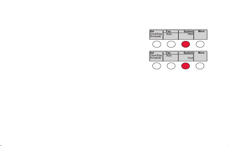
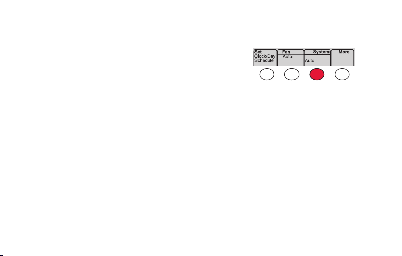
Selecting system mode
MCR33880
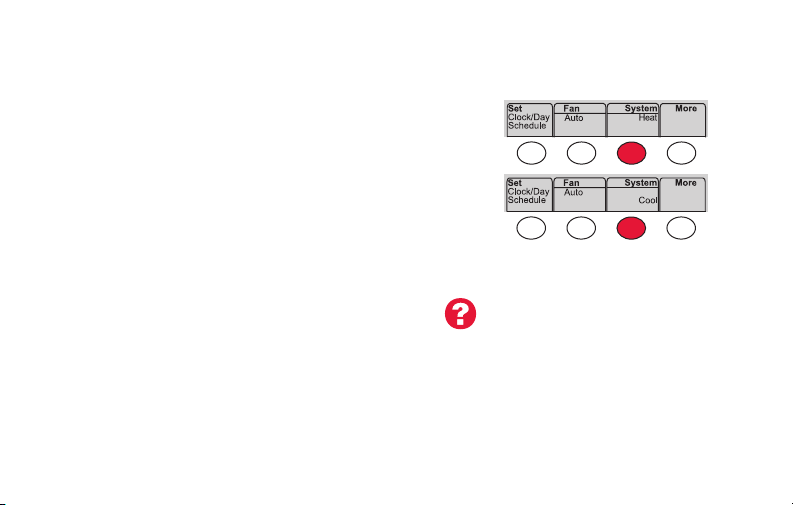
Press System to select:
Heat: Controls only the heating system.
Cool: Controls only the cooling system.
Off: Heating/cooling systems are off.
Auto
: Selects heating or cooling depending on
the indoor temperature.
Em Heat (heat pumps with aux. heat):
Controls auxiliary/emergency heat.
Compressor is off.
69-2718ES—03 38
Note: Depending on how
your thermostat was installed,
you may not see all system
settings.
Page 41

Adjusting program schedules
MCR33892
1 Press Set Clock/Day/Schedule, then Set Schedule.
2 Press s or t to set your Monday (Mon) Wake
time, then press Next.
3 Press s or t to set the temperature for this
period, then press Next.
4 Set time and temperature for the next time
period (Leave). Repeat Steps 2 and 3 for each
time period.
5 Press Next to set time periods for the next day.
Repeat Steps 2 through 4 for each day.
6 Press Done to save and exit.
Note: Make sure the thermostat is set to the
system mode you want to program (Heat or Cool).
39 69-2718ES—03
Page 42

Overriding schedules temporarily
MCR33896
Press s or t to immediately adjust the
temperature.
The new temperature will be maintained only
until the next programmed time period begins.
To cancel the temporary setting at any time,
press Cancel. The program schedule will
resume.
69-2718ES—03 40
HOLD
Page 43

Overriding schedules permanently
1 Press HOLD to permanently adjust the
temperature. This will turn off the program
schedule.
2 Press s or t to adjust the temperature
setting. The temperature you set will
be maintained 24 hours a day until you
manually change it or press Cancel to
resume the program schedule
41 69-2718ES—03
HOLD
MCR33897
Page 44

Unregistering thermostat
M33876
If you remove the thermostat from your
Total Connect Comfort website account
(for example, you’re moving and leaving
the thermostat behind), the thermostat will
display Register at Total Connect until it is
re-registered.
69-2718ES—03 42
Page 45

Disconnecting Wi-Fi
M33855
Replacing your router
If you disconnect the thermostat from your Wi-Fi network:
1 Enter system setup (see page 48).
2 Change setting 39 to 0 (see page 54).
The screen will display Wi-Fi Setup.
Re-connect to a Wi-Fi network by following the steps on page 26.
Turning Wi-Fi off
If you do not plan to control the thermostat remotely, you can remove the Wi-Fi Setup
message from the screen:
1 Enter system setup (see page 48).
2 Change setting 38 to 0 (see page 54). Wi-Fi Setup will be removed from the screen.
If you want to connect to the Wi-Fi network later, change setting 38 back to 1.
43 69-2718ES—03
Page 46

Software updates
Honeywell periodically issues updates to the software for
this thermostat. The updates occur automatically through
your Wi-Fi connection. All your settings are saved, so
you will not need to make any changes after the update
occurs.
While the update is taking place, your thermostat screen
flashes Updating and shows the percentage of the update
that has occurred. When the update is complete, your
home screen will appear as usual.
Note: If you are not connected to Wi-Fi, you will not get
automatic updates.
69-2718ES—03 44
Percentage of
update complete
Page 47

Smart Response Technology
M33881
This feature allows the thermostat to “learn”
how long the heating/cooling system takes to
reach programmed temperature settings, so
the temperature is reached at the time you set.
For example: Set the Wake time to 6:00 am,
and the temperature to 70°. The heat will come
on before 6:00 am, so the temperature is 70°
by 6:00 am.
Note: System setting function 13 controls
Smart Response Technology. See “Smart
Response Technology” on page 52.
45 69-2718ES—03
The message Recovery is
displayed when the system
is activated before a
scheduled time period.
Page 48

Compressor protection
M33882
This feature forces the compressor to wait
a few minutes before restarting, to prevent
equipment damage.
69-2718ES—03 46
The message Cool On
(or Heat On for a heat
pump) will flash during
the wait time.
Page 49
Auto changeover
MCR33893
This feature is used in climates where both
air conditioning and heating are used on the
same day.
When the system is set to Auto,
the thermostat automatically
selects heating or cooling
depending on the indoor temperature.
Heat and cool settings must be at least
3 degrees apart. The thermostat will
automatically adjust settings to maintain this
3-degree separation.
Note: System setting function 12 controls
Auto changeover. See “Manual/Auto
Changeover” on page 51.
47 69-2718ES—03
Page 50

Setting functions and options
You can change options for a number of system functions. Available functions depend on
the type of system you have. The functions, along with available options, are described on
pages 50–54.
This thermostat is pre-set for a single-stage heating/cooling system. Setting function 1 for
a heat pump will adjust the default settings.
69-2718ES—03 48
Page 51
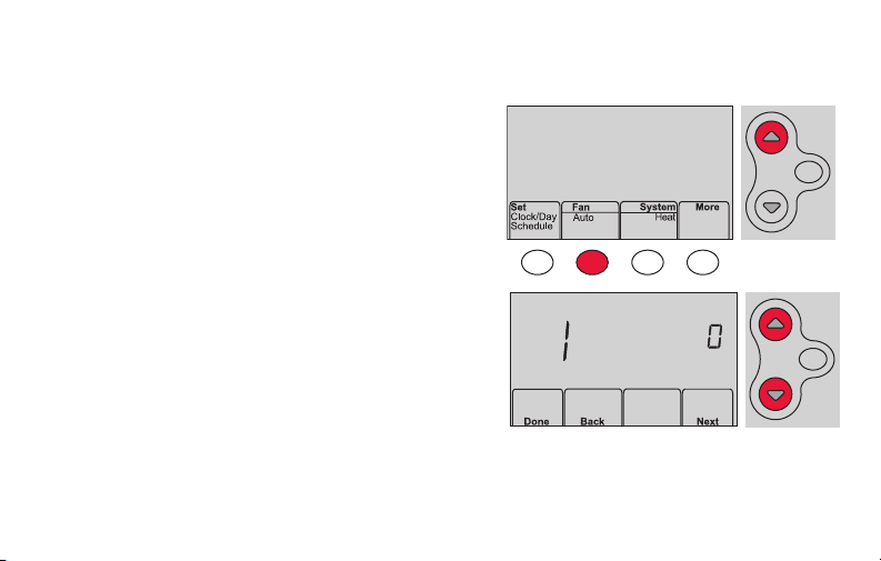
Setting functions and options
MCR33883
MCR33884
1 Press Fan and s simultaneously and hold
for approximately 3 seconds. The screen
will change to display two numbers and the
button designations will be Done, Back, blank,
Next.
2 Press Next until you see the function
number—the larger number on the left—
you want to set.
3 Change options for any function by pressing
s or t until the correct option (smaller
number on right) is displayed.
4 Repeat Steps 2 and 3 until you have set all
functions that you wish to change.
5 When you have made all changes, press
Done to save and exit.
49 69-2718ES—03
HOLD
HOLD
Page 52
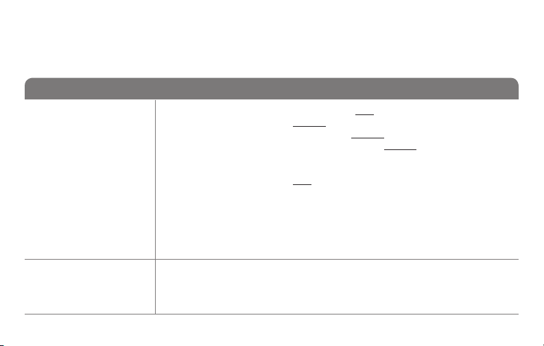
System setup
(See page 48 for instructions.)
Function Settings & Options
Select System
1
Type
If you are not sure
of your heating/
cooling system
type or have other
questions, go to
withermostat.com
Heat Pump
2
Changeover Valve
(for heat pumps
only)
69-2718ES—03 50
0 Heat/cool: Gas, oil or electric heating with central air conditioning.
1 Heat pump: Heat pump without backup or auxiliary heat.
2 Heat only: Gas, oil or hot water heat without central air conditioning.
3 Heat only with fan: Gas, oil or electric heat without central air
conditioning.
4 Cool only: Central air conditioning only.
5 Heat pump: Heat pump with backup or auxiliary heating.
6 Heat/Cool Multiple stages: 2 heat stages (wires on W and W2), 2
cooling stages (wires on Y and Y2).
7 Heat/Cool Multiple stages: 2 heat stages (wires on W and W2), 1
cooling stage (wire on Y).
8 Heat/Cool Multiple stages: 1 heat stage (wires on W), 2 cooling stages
(wire on Y and Y2).
0 Cooling changeover valve: Use this setting if you connected a wire
labeled “O” to the O/B terminal.
1 Heating changeover valve: Use this setting if you connected a wire
labeled “B” to the O/B terminal.
Page 53

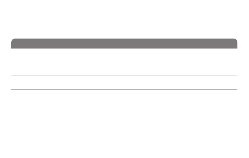
System setup
(See page 48 for instructions.)
Function Settings & Options
Heating Fan
3
Control
Heating Cycle
5
Rate
Heating Cycle
6
Rate Stage 2
Manual/Auto
12
Changeover
See page 47 for
more information.
51 69-2718ES—03
0 Gas or oil heat: Use this setting if you have a gas or oil heating system
(system controls fan operation).
1 Electric heat: Use this setting if you have an electric heating system
(thermostat controls fan operation).
5 Gas or oil furnace: Standard gas/oil furnace (less than 90% efficiency).
9 Electric furnace: Electric heating systems.
3 Hot water or high-efficiency furnace: Hot water system or gas furnace
(more than 90% efficiency).
1 Gas/oil steam or gravity system: Steam or gravity heat systems.
0 Manual changeover (Heat/Cool/Off).
1 Automatic changeover (Heat/Cool/Auto/Off). Automatically turns on Heat
or Cool based on room temperature. Note: System maintains minimum
3°F difference between heat and cool settings.
Page 54
System setup
(See page 48 for instructions.)
Function Settings & Options
Smart Response
13
Technology
See page 45 for
more information.
Temperature
14
Format (°F/°C)
Schedule Options
16
69-2718ES—03 52
1 On
0 Off
0 Fahrenheit
1 Celsius
1 Program schedule is on (7-day programmable).
0 Program schedule is off. Thermostat can not be programmed.
Page 55

System setup
(See page 48 for instructions.)
Function Settings & Options
Device Name
36
This name will
identify the
thermostat when
you view it remotely.
If you register
multiple thermostats,
give each one a
different name.
53 69-2718ES—03
52 = Thermostat
1 Basement 16 Exercise Room 30 Library 44 Porch
2 Bathroom 17 Family Room 31 Living Room 45 Rec Room
3 Bathroom 1 18 Fireplace 32 Lower Level 46 Sewing Room
4 Bathroom 2 19 Foyer 33 Master Bath 47 Spa
5 Bathroom 3 20 Game Room 34 Master Bed 48 Storage Room
6 Bedroom 21 Garage 35 Media Room 49 Studio
7 Bedroom 1 22 Great Room 36 Music Room 50 Sun Room
8 Bedroom 2 23 Guest Room 37 Nursery 51 Theater
9 Bedroom 3 24 Gym 38 Office 52 Thermostat
10 Bedroom 4 25 Kid's Room 39 Office 1 53 Upper Level
11 Boat House 26 Kitchen 40 Office 2 54 Utility Room
12 Bonus Room 27 Kitchen 1 41 Pantry 55 Walk In Closet
13 Computer Room 28 Kitchen 2 42 Play Room 56 Wine Cellar
14 Den 29 Laundry Room 43 Pool Room 57 Workshop
15 Dining Room
Page 56

System setup
(See page 48 for instructions.)
Function Settings & Options
Wi-Fi On/Off
38
Wi-Fi Connection
39
Show period and
42
day of week
Restore Schedule
85
Defaults
Restore Original
90
Settings
69-2718ES—03 54
1 Wi-Fi is on and can be connected to a Wi-Fi network.
0 Wi-Fi is off. Thermostat cannot be connected to a Wi-Fi network. If you
are not connecting the thermostat to a Wi-Fi network this will remove the
text Wi-Fi Setup from the messaging center.
1 Connected to Wi-Fi network. This is set automatically when the
thermostat is connected to the Wi-Fi network.
0 Set to 0 to disconnect from the Wi-Fi network.
0 Period and day are not shown on the home screen.
1 Period and day are shown on the home screen.
0 Continue using programmed schedule.
1 Restore thermostat program to energy saving settings
0 No
1 Disconnects thermostat from Wi-Fi and restores original settings (erases
customizations).
Page 57

Frequently asked questions
:Q Will my thermostat still work if I lose my Wi-Fi connection?
:A Yes, the thermostat will operate your heating and/or cooling system with or without Wi-Fi.
:Q How do I find the password to my router?
:A Contact the manufacturer of the router or check the router documentation.
:Q Why am I not seeing my Wi-Fi setup page?
:A You are probably connected only to your router, not to your thermostat. Try connecting to the
thermostat again.
:Q Why isn’t my thermostat connecting to my Wi-Fi router even though it is very close to the
thermostat?
:A Verify that the password entered for the Wi-Fi router is correct.
55 69-2718ES—03
Page 58

Frequently asked questions
:Q Where can I find my MAC ID and MAC CRC codes?
:A The MAC ID and MAC CRC numbers are included on a card packed with the thermostat or on the
back of the thermostat (visible when removed from wallplate). Each thermostat has a unique MAC
ID and MAC CRC.
:Q My thermostat is unable to register to the Total Connect Comfort website.
:A Verify that the thermostat is correctly enrolled on your home Wi-Fi network. The message center
will display Wi-Fi Setup or Register at Total Connect. You might also see the Wi-Fi Signal strength
icon. Verify that the Wi-Fi router has a good internet connection. On your computer, verify that
you can open the site at mytotalconnectcomfort.com
If you cannot open the site, switch off the internet modem for a few seconds, then power it
back on.
69-2718ES—03 56
Page 59

Frequently asked questions
:Q I registered on the Total Connect Comfort website but was unable to login using my new
account.
:A Check your email and ensure that you received an activation email. Follow the instructions to
activate your account and then login to the website.
:Q I have signed up on the Total Connect Comfort website and have not received a
confirmation email.
:A Check for the email in your Junk or Deleted folder.
:Q Is there a way to extend the signal strength?
:A Most standard routers can be set up to be a repeater. You can also purchase and install a Wi-Fi
repeater.
For more FAQs, see wifithermostat.com/support
57 69-2718ES—03
Page 60

Troubleshooting
Lost Signal
If the no-Wi-Fi indicator displays in place of the
Wi-Fi strength indicator in the upper right hand
corner of the home screen:
• Check another device to be sure Wi-Fi is
working in your home; if not, call your Internet
Service Provider.
• Move the router.
• Restart the thermostat: remove it from the
wallplate, wait 10 seconds, and snap it
back onto the wallplate. Return to Step 1 of
Connecting to your Wi-Fi network.
69-2718ES—03 58
M33997M33997
Page 61

Troubleshooting
Error Codes
For certain problems, the thermostat screen will display
a code that identifies the trouble. Initially, error codes are
displayed alone in the time area of the screen; after a
few minutes, the home screen is displayed and the code
alternates with the time.
Error Code Action
During Wi-Fi Setup, the router
E01
lost power.
• Ensure your router has power.
• If trying to connect to a hidden or manually added network,
confirm the router has power and is working.
Invalid Wi-Fi password. This
E02
code displays for 30 seconds,
then the thermostat will re-enter
Wi-Fi Setup mode.
59 69-2718ES—03
• Re-enter password for your home Wi-Fi network.
• Repeat setup process and confirm your password for your home
Wi-Fi network.
Page 62

Troubleshooting
Error Code Action
Router is not issuing
E42
an IP address to the
thermostat.
No internet connection.
E43
Thermostat cannot
communicate to Total
Connect Comfort.
General error Remove thermostat from wallplate for
E99
69-2718ES—03 60
• Wait for 30 minutes, connection can
take several minutes.
• If still no connection, remove
thermostat from wallplate for 10
seconds, then reconnect it (see page
26).
• Verify your router is correctly setup to
automatically give IP addresses.
• Make sure the Internet cable is
plugged in.
• Reboot the router.
10 seconds, then reconnect it (see
26).
page
Page 63

Troubleshooting
If you have difficulty with your thermostat, please try the following suggestions.
Most problems can be corrected quickly and easily.
Display is
blank
• Check circuit breaker and reset if necessary.
• Make sure power switch at heating and cooling system is on.
• Make sure furnace door is closed securely.
• Make sure C wire is connected (see page 13).
Cannot change
system setting
to Cool
Fan does
not turn on
when heat is
required
Cool On or Heat
On is flashing
on the screen
61 69-2718ES—03
• Check Function 1: System Type to make sure it is set to match your heating
and cooling equipment (see page 50).
• Check Function 3: Heating Fan Control to make sure it is set to match your
heating equipment (see page 51).
• Compressor protection feature is engaged. Wait 5 minutes for the system to
restart safely, without damage to the compressor.
Page 64

Troubleshooting
Heat pump
issues cool air
in heat mode,
or warm air in
cool mode
Heating or
cooling system
does not
respond
69-2718ES—03 62
• Check Function 2: Heat Pump Changeover Valve to make sure it is properly
configured for your system (see page 50).
• Press System to set system to Heat. Make sure the temperature is set higher
than the Inside temperature.
• Press System to set system to Cool. Make sure the temperature is set lower
than the Inside temperature.
• Check circuit breaker and reset if necessary.
• Make sure power switch at heating & cooling system is on.
• Make sure furnace door is closed securely.
• Wait 5 minutes for the system to respond.
Page 65

Troubleshooting
Heating system
is running in
cool mode
Heating
and cooling
equipment are
running at the
same time
63 69-2718ES—03
• Check Function 1: System Type to make sure it is set to match your heating
and cooling equipment (see page 50).
• Check Function 1: System Type to make sure it is set to match your heating
and cooling equipment (see page 50).
• Grasp and pull thermostat away from wallplate. Check to make sure bare
wires are not touching each other.
• Check thermostat wiring is correct.
Page 66

Glossary
C wire
The “C” or common wire brings 24 VAC power to the thermostat from the heating/cooling system.
Some older mechanical or battery operated thermostats may not have this wire connection. It is
necessary for establishing a Wi-Fi connection to your home network.
Heat Pump heating/cooling system
Heat pumps are used to heat and cool a home. If your old thermostat has a setting for auxiliary or
emergency heat, you likely have a heat pump.
Conventional heating/cooling system
Non–heat pump type systems; these include air handlers, furnaces or boilers that run on natural gas,
oil or electricity. They may or may not include an air conditioner.
Jumper
A small piece of wire that connects two terminals together.
MAC ID, MAC CRC
Alphanumeric codes that uniquely identify your thermostat.
QR Code
Quick response code. A two-dimensional,machine-readable image. Your wireless device can read
the black and white pattern in the square and link its browser directly to a web site. QR Code is a
registered trademark of DENSO WAVE INCORPORATED.
69-2718ES—03 64
®
Page 67

Regulatory information
FCC Compliance Statement (Part 15.19) (USA only)
This device complies with Part 15 of the FCC Rules.
Operation is subject to the following two conditions:
1 This device may not cause harmful interference, and
2 This device must accept any interference received,
including interference that may cause undesired
operation.
FCC Warning (Part 15. 21) (USA only)
Changes or modifications not expressly approved by the
party responsible for compliance could void the user’s
authority to operate the equipment.
FCC Interference Statement (Par t 15.105 (b))
(USA only)
This equipment has been tested and found to comply
with the limits for a Class B digital device, pursuant to
Part 15 of the FCC Rules. These limits are designed
to provide reasonable protection against harmful
interference in a residential installation. This equipment
generates uses and can radiate radio frequency energy
and, if not installed and used in accordance with the
instructions, may cause harmful interference to radio
communications. However, there is no guarantee that
interference will not occur in a particular installation. If
this equipment does cause harmful interference to radio
or television reception, which can be determined by
turning the equipment off and on, the user is encouraged
to try to correct the interference by one of the following
measures:
• Reorient or relocate the receiving antenna.
• Increase the separation between the equipment and
receiver.
• Connect the equipment into an outlet on a circuit
different from that to which the receiver is connected.
• Consult the dealer or an experienced radio/TV
technician for help.
65 69-2718ES—03
Page 68

Regulatory information
Thermostats
To comply with FCC and Industry Canada RF exposure
limits for general population/ uncontrolled exposure, the
antenna(s) used for these transmitters must be installed
to provide a separation distance of at least 20 cm from
all persons and must not be co-located or operating in
conjunction with any other antenna or transmitter.
RSS-GEN
Under Industry Canada regulations, this radio transmitter
may only operate using an antenna of type and
maximum (or lesser) gain approved for the transmitter by
Industry Canada. To reduce potential radio interference
to other users, the antenna type and its gain should
be so chosen that the equivalent isotropically radiated
power (e.i.r.p.) is not more than that necessary for
successful communication.
69-2718ES—03 66
Operation is subject to the following two conditions:
1 this device may not cause interference, and
2 this device must accept any interference, including
interference that may cause undesired operation of the
device.
Page 69

1-year limited warranty
Honeywell warrants this product, excluding battery, to be free from defects in the workmanship or materials, under normal use and
service, for a period of one (1) year from the date of purchase by the consumer. If at any time during the warranty period the product is
determined to be defective or malfunctions, Honeywell shall repair or replace it (at Honeywell’s option).
If the product is defective,
(i) return it, with a bill of sale or other dated proof of purchase, to the place from which you purchased it; or
(ii) call Honeywell Customer Care at 1-855-733-5465. Customer Care will make the determination whether the product should be
returned to the following address: Honeywell Return Goods, Dock 4 MN10-3860, 1885 Douglas Dr. N., Golden Valley, MN 55422, or
whether a replacement product can be sent to you.
This warranty does not cover removal or reinstallation costs. This warranty shall not apply if it is shown by Honeywell that the defect or
malfunction was caused by damage which occurred while the product was in the possession of a consumer.
Honeywell’s sole responsibility shall be to repair or replace the product within the terms stated above. HONEYWELL SHALL NOT
BE LIABLE FOR ANY LOSS OR DAMAGE OF ANY KIND, INCLUDING ANY INCIDENTAL OR CONSEQUENTIAL DAMAGES
RESULTING, DIRECTLY OR INDIRECTLY, FROM ANY BREACH OF ANY WARRANTY, EXPRESS OR IMPLIED, OR ANY OTHER
FAILURE OF THIS PRODUCT. Some states do not allow the exclusion or limitation of incidental or consequential damages, so this
limitation may not apply to you.
THIS WARRANTY IS THE ONLY EXPRESS WARRANTY HONEYWELL MAKES ON THIS PRODUCT. THE DURATION OF ANY
IMPLIED WARRANTIES, INCLUDING THE WARRANTIES OF MERCHANTABILITY AND FITNESS FOR A PARTICULAR PURPOSE,
IS HEREBY LIMITED TO THE ONE-YEAR DURATION OF THIS WARRANTY. Some states do not allow limitations on how long an
implied warranty lasts, so the above limitation may not apply to you.
This warranty gives you specific legal rights, and you may have other rights which vary from state to state.
If you have any questions concerning this warranty, please write Honeywell Customer Relations, 1985 Douglas Dr, Golden Valley, MN
55422 or call 1-855-733-5465. In Canada, write Retail Products ON15-02H, Honeywell Limited/Honeywell Limitée, 35 Dynamic Drive,
Toronto, Ontario M1V4Z9.
67 69-2718ES—03
Page 70

Automation and Control Systems
69-2718ES-05
Honeywell International Inc.
1985 Douglas Drive North
Golden Valley, MN 55422
wifithermostat.com
® U.S. Registered Trademark.
Apple, iPhone, iPad, iPod touch and iTunes are trademarks of Apple Inc.
All other trademarks are the property of their respective owners.
© 2015 Honeywell International Inc.
69-2718ES —05 M.S. Rev. 01-15
Printed in U.S.A.
Page 71
Guía del usuario
Termostato programable
con conexión WiFi
Serie Red inalámbrica (Wi-Fi)
RTH6500WF
Page 72

En la caja, encontrará lo siguiente:
• Termostato
• Placa de pared (adherida al
termostato)
• Tornillos y anclajes
• Guía para el encendido rápido
• Tarjeta de identificación del
termostato
• Etiquetas de los cables
• Guía del usuario
• Tarjeta de referencia rápida
69-2718ES—03 ii
Page 73

Bienvenido
Felicitaciones por la compra del termostato
programable con conexión WiFi de Honeywell.
Cuando se registre en Total Connect Comfort
Solutions de Honeywell, puede supervisar
y controlar de manera remota el sistema de
calefacción y refrigeración de su hogar o
empresa; puede permanecer conectado a su
sistema de confort dondequiera que vaya.
Total Connect Comfort de Honeywell es la
solución perfecta si usted viaja frecuentemente,
si posee un hogar de vacaciones o una
empresa, o si administra una propiedad de
inversión o, simplemente, busca tranquilidad.
Page 74

Este termostato funciona con sistemas comunes de 24 voltios, como aplicaciones
de aire forzado, hidrónicas, de una bomba de calor, de aceite, de gas y eléctricas.
No funciona con sistemas de milivoltios, como una chimenea a gas, ni con sistemas
de 120/240 voltios, como la calefacción de zócalo eléctrica.
AVISO SOBRE MERCURIO: No coloque el termostato existente en la basura si
este contiene mercurio en un tubo sellado. Comuníquese con Thermostat Recycling.
Corporation en www.thermostat-recycle.org o al 1-800-238-8192 para obtener
información sobre cómo y dónde desechar el termostato de manera adecuada y
segura.
AVISO: Para evitar posibles daños al compresor, no utilice el aire acondicionado si
la temperatura externa es inferior a 50 °F (10 °C).
¿Necesita ayuda?
Visite wifithermostat.com o llame al 1-855-733-5465 para obtener asistencia antes de
devolver el termostato a la tienda.
69-2718ES—03 2
Page 75

Índice
Acerca de su nuevo termostato
Referencia rápida de los controles
y la pantalla de inicio ..................................5
Cronogramas de ahorro de
energía predeterminados ............................ 6
Instalación
Instalación del termostato ........................... 8
Conexión a la red WiFi ..............................26
Registro del termostato en línea ............... 31
Funcionamiento
Setting the time and day ........................... 36
Configuración del ventilador .....................37
Selección de la modalidad del sistema ....38
Ajuste de los cronogramas
del programa ............................................. 39
Anulación temporal de los cronogramas...40
69-2718ES—03 3
Anulación permanente
de los cronogramas ..................................41
Baja del termostato ................................... 42
Desconexión de la red WiFi ......................43
Características especiales ........................ 45
Opciones y funciones de configuración .... 48
Apéndices
Preguntas frecuentes ................................ 55
Localización y solución de problemas ......61
Garantía limitada ....................................... 67
Page 76

Características del termostato con conexión WiFi
Con el nuevo termostato, podrá realizar lo siguiente:
• Conectarse a Internet para supervisar y controlar el sistema de calefacción/
refrigeración
• Ver y cambiar las configuraciones del sistema de calefacción/refrigeración
• Ver y configurar la temperatura y los cronogramas
• Recibir alertas por correo electrónico y obtener actualizaciones automáticas
El nuevo termostato ofrece lo siguiente:
• Tecnología Smart Response
• Protección del compresor
• Cambio automático de calor/frío
69-2718ES—03 4
Page 77

Referencia rápida de los controles y la pantalla de inicio
M31586
Una vez que el termostato con conexión WiFi esté instalado, podrá visualizar la pantalla
de inicio. Partes de esta pantalla cambiarán según cómo la vea.
Los mensajes
para configurar
describen los pasos
para el proceso de
configuración de WiFi
Configuración del reloj,
el día o el cronograma
Selección de las
configuraciones del
ventilador
HOLD
Selección de
la modalidad
del sistema
Estado de la
conexión WiFi
Botones de regulación
de la temperatura
Botón de anulación
permanente
Configuraciones
adicionales
La pantalla se ilumina cuando presiona cualquier botón. Permanece iluminada durante
8 segundos después de que efectúa cambios.
5 69-2718ES—03
Page 78

Cronogramas de ahorro de energía predeterminados
Este termostato cuenta con configuraciones del programa de ahorro de energía
predeterminadas durante cuatro períodos. Si utiliza las configuraciones predeterminadas,
puede reducir los gastos de calefacción/refrigeración, siempre que siga las instrucciones.
Los ahorros pueden varias según la región geográfica y el uso. Para cambiar las
configuraciones, consulte las páginas 39–41.
Configuraciones
predeterminadas de calor
WAKE (Despertar)
6:00 am
LEAVE (Salir)
8:00 am
RETURN (Regresar)
6:00 pm
SLEEP (Dormir)
10:00 pm
69-2718ES—03 6
70
62
70
62
Configuraciones
predeterminadas de frío
°
°
°
°
78
85
78
82
°
°
°
°
Page 79

Configuración del termostato
Configurar el termostato programable es fácil. Está preprogramado y listo para funcionar
tan pronto como se instale y se registre.
Instale su termostato.
1
Conecte a su red doméstica WiFi.
2
Regístrelo a través de Internet para obtener acceso remoto.
3
Antes de comenzar, le recomendamos que mire un breve video de
instalación. Utilice el QR Code® en la parte delantera de esta guía o visite
wifithermostat.com/support
7 69-2718ES—03
Page 80
Instalación del termostato
Es posible que necesite las siguientes herramientas para instalar el termostato:
• Destornillador Phillips n.° 2
• Destornillador de bolsillo pequeño
• Lápiz
• Nivel (opcional)
• Taladro y brocas (3/16” [4.8 mm] en
paneles de yeso,
7/32” [5.5 mm] en yeso) (opcional)
1 DESCONECTE la energía de su
sistema de calefacción/refrigeración.
¡Importante! Para proteger el equipo,
DESCONECTE la energía eléctrica de
su sistema de calefacción/refrigeración
en la caja de interruptores de circuito
o el interruptor del sistema.
69-2718ES—03 8
• Martillo (opcional)
• Cinta aislante (opcional)
o
Caja de interruptores
de circuito
Interruptor de energía
del sistema de
calefacción/
refrigeración
Page 81

Instalación del termostato
2 Retire el termostato existente.
2a Tome una fotografía de las
conexiones de los cables para
usar de referencia más adelante.
Si el termostato existente tiene
un tubo de mercurio sellado, vaya
a la página 2 para obtener
instrucciones sobre cómo desecharlo
adecuadamente.
2b Si ningún cable está conectado
al terminal con la marca C o
no existe un terminal C en el
termostato existente, mire el
video Alternate Wiring (Cableado
alternativo) en
C
C
wifithermostat.com/videos
¡Importante! El cable C es
necesario y es la principal fuente de
energía para su termostato. Sin un
Designación de
los terminales
cable C, su termostato no encenderá.
9 69-2718ES—03
Page 82

Instalación del termostato
3 Etiquete los cables.
No etiquete por color del cable. Utilice
las etiquetas adhesivas suministradas
para identificar cada cable a medida
que los desconecta. Etiquete los cables
conforme a las designaciones de los
terminales del termostato existente, no
según el color de los cables.
Nota: If si ninguna etiqueta coincide
con las demás, etiquete el terminal del
cable utilizando una etiqueta en blanco.
4 Quite la placa de pared.
Quite la placa de pared existente de la
pared después de que haya etiquetado
y desconectado todos los cables.
69-2718ES—03 10
Etiqueta
autoadhesiva
Etiqueta
autoadhesiva
en blanco
C
C
Designación
de los
terminales
Page 83

Instalación del termostato
5 Separe el termostato con conexión
WiFi y la placa de pared.
En el nuevo termostato, sostenga, con
Termostato
Orificios de
sujeción
una mano, la placa de pared desde
los orificios de sujeción en la parte
superior e inferior y, con la otra, el
PULL HERE
TO REMOVE
termostato (frente). Separe las piezas.
PULL HERE
TO REMOVE
M33856
Placa de pared
(vista posterior)
11 69-2718ES—03
Page 84
Instalación del termostato
MCR33857
6 Monte la placa de pared para
termostato con conexión WiFi.
Monte la nueva placa de pared con
los tornillos y anclajes incluidos con el
termostato.
Si fuese necesario:
Taladre agujeros de 3/16 in (4.8 mm) en
paneles de yeso.
Taladre agujeros de 7/32 in (5.6 mm)
en yeso.
Nota: puede usar los tarugos de pared
existentes. Sostenga la placa de pared
con los tarugos existentes para controlar
la alineación.
Placa de pared
69-2718ES—03 12
Page 85

Instalación del termostato
¡Importante! el termostato con conexión WiFi requiere de un cable C para que funcione.
El cable C, o común, le transmite 24 V CA al termostato. Muchos termostatos mecánicos
o con batería más antiguos no requieren de un cable C. Si no tiene un cable C, intente
hacer lo siguiente:
• Busque un cable sin usar que esté introducido en la pared. Conecte ese cable a C y
verifique que esté conectado a 24 V CA en el sistema de calefacción/refrigeración.
Nota: No todos los sistemas de calefacción/refrigeración identifican el terminal común C
de 24 V CA. Revise su manual del sistema o comuníquese con el fabricante para conocer
cuál es el terminal común de 24 V CA.
Mire los videos Alternate Wiring (Cableado alternativo) en wifithermostat.com/videos
Cableado
Para obtener sistemas de calefacción/refrigeración convencionales (gas natural, aceite
o eléctricos, aire acondicionado), consulte la página 14. Para obtener más definiciones,
consulte el “Glosario” en la página 64.
Para obtener un sistema de bomba de calor, consulte la página 15. Para obtener más
definiciones, consulte el “Glosario” en la página 64.
13 69-2718ES—03
Page 86
Instalación del termostato
BOMBA DE CALOR
Cableado (sistema convencional)
7A Coloque el cableado del termostato con
conexión WiFi en su sistema convencional.
a Comience con el cable C y coloque la etiqueta autoadhesiva
en el cable con las etiquetas del terminal.
Debe tener un cable C. Refiérase a la página 13.
b Afloje el tornillo, inserte el cable en el borde
interior del terminal, luego, ajuste el tornillo.
c Verifique que el cable esté bien ajustado jalando,
suavemente, del cable.
d Repita los pasos a–c para todos los cables
restantes.
e Una vez que estén instalados todos los cables,
introduzca el excedente de cable en la abertura
de la pared.
f Continúe con la página 20.
¿Las etiquetas no coinciden? Consulte la clave para la
instalación de cableado alternativo en las páginas 16 y 17.
69-2718ES—03 14
Extraiga el puente
de metal solo si
tiene cables R y RC.
W
G
Y
R
C
C
G W
Y2
W2
AUX/E
L
G O/B
YR RCK
CONVENCIONAL
C
YRRCK
Nota: el cableado de
su aplicación puede
diferir del cableado que
se muestra arriba.
Page 87
Instalación del termostato
DE CALOR
Cableado (sistema de bomba de calor únicamente)
7B Coloque los cables del termostato con conexión WiFi a su
bomba de calor.
a Comience con el cable C y coloque la etiqueta autoadhesiva
en el cable con las etiquetas del terminal.
Debe tener un cable C. Refiérase a la página 13.
b Afloje el tornillo, inserte el cable en el borde interior del
¿Las etiquetas
no coinciden?
Consulte la clave
para la instalación
de cableado
alternativo en las
páginas 18–19.
terminal, luego, ajuste el tornillo.
c Verifique que el cable esté bien ajustado jalando,
suavemente, del cable.
d Repita los pasos a–c para todos los cables restantes.
e Una vez que estén instalados todos los cables, introduzca
O
G
Aux
R
Y
el excedente de cable en la abertura de la pared.
f Continúe con la página 20.
Nota: Si el termostato existente tiene cables separados
en AUX y E, coloque los dos cables en el terminal
E/AUX. Si el termostato existente tiene un cable en
AUX con un puente conectado a E, coloque el cable
en el terminal E/AUX. No necesita un puente.
15 69-2718ES—03
Nota: el cableado de su
aplicación puede diferir del
cableado que se muestra arriba.
AUX/E
L
G O/B
C
BOMBA
YRRCK
Page 88
Instalación del termostato
MSCR33885
Cableado alternativo (sistema convencional)
Utilícelo si las etiquetas de los cables no coinciden con las etiquetas de los terminales.
2
Y2
Nota: debe tener un
cable C o equivalente.
Refiérase a la página 13.
W2
C
o
o
W1F
H
RYWG
RC
o
o
X
B
C1
o
o
R
RHY1
4M
V
1
W2
G W
Y2
K
69-2718ES—03 16
C
YRRC
CONVENCIONAL
3
Consulte las claves de
1
a 3 en la página 17.
Page 89

Instalación del termostato
Clave para cableado alternativo (sistema convencional)
No utilice el terminal K. Para uso futuro.
1
Si su termostato existente tenía cables R y RH, extraiga el puente de metal.
2
Conecte el cable R al terminal RC, y el cable RH al terminal R.
Retire el puente de metal que conecta los terminales R y RC solo si debe
3
conectar los dos, R y RC.
17 69-2718ES—03
Page 90

Instalación del termostato
BOMBA DE CALOR
Cableado alternativo (sistema de bomba de calor únicamente)
Utilícelo si las etiquetas de los cables no coinciden con las etiquetas de los terminales.
3
Nota: debe tener un
cable C o equivalente.
Refiérase a la página 13.
2
EAUX
L
oooo oo oo o
XW FH
F
X2
1
4
OG
W1
W2
5
4
6
C
RY
X
B
B
RC
R
VY1
VRM
7
AUX/E
L
69-2718ES—03 18
G O/B
C
YRRCK
MSCR33886
Consulte las claves de
1
– 7 en la página 19.
Page 91

Instalación del termostato
Clave para cableado alternativo (sistema de bomba de calor únicamente)
No utilice el terminal K. Para uso futuro.
1
Si el termostato existente tiene cables separados en AUX y E, coloque los dos cables en el
2
terminal E/AUX. Si el termostato existente tiene un cable en AUX con un puente conectado a
E, coloque el cable en el terminal E/AUX. No necesita un puente.
Si su termostato existente tenía un cable O en lugar de un cable B, conecte el cable O al
3
terminal O/B.
Si su termostato existente tenía cables O y B separados, conecte el cable B al terminal C. Si se
4
conecta otro cable al terminal C, visite wifithermostat.com para obtener ayuda. Conecte el cable
O al terminal O/B.
Si el termostato existe tenía cables Y1, W1 y W2 separados, visite wifithermostat.com para
5
obtener ayuda.
Si su termostato existente tenía cables V y VR, visite wifithermostat.com para obtener ayuda.
6
Deje el puente de metal que se encuentra entre los terminales R y RC en el lugar.
7
19 69-2718ES—03
Page 92

Instalación del termostato
8 Inserte la tarjeta de
referencia rápida.
Doble la tarjeta de referencia
rápida en tres partes por
las líneas marcadas y
deslícela en la ranura entre
el termostato y la placa de
pared.
69-2718ES—03 20
Tarjeta de
referencia
rápida
MCR33916
Parte posterior del termostato
Page 93

Instalación del termostato
M33860
9 Conecte el termostato a la placa de
pared.
Alinee el termostato con la placa de
pared y presiónelo para que calce
en su lugar.
HOLD
21 69-2718ES—03
Page 94

Instalación del termostato
10 Encienda el sistema de calefacción/
refrigeración.
¡Importante!
10a Verifique que el cable C esté
conectado al termostato y
al sistema de calefacción/
refrigeración.
10b Verifique que la puerta del
sistemas de calefacción/
refrigeración esté bien cerrada.
10c Vuelva a ENCENDER su sistema
de calefacción/refrigeración en la
caja de interruptores de circuito o
su interruptor de energía.
69-2718ES—03 22
Caja de interruptores
de circuito
o
Interruptor de energía
del sistema de
calefacción/
refrigeración
Page 95

Instalación del termostato
MCR33909
11 Configure el reloj al día y hora
actual.
11a Presione s o t para
configurar el reloj.
11b Presione Set Day.
11c Presione s o t para
seleccionar el día de la
semana.
11d Presione Done (terminado)
para guardar.
(Presione y sostenga un
botón st para cambiar una
configuración rápidamente.)
HOLD
MCR33908
HOLD
23 69-2718ES—03
Page 96
Instalación del termostato
12 Determine el tipo de sistema de calefacción/refrigeración.
¡Importante! El tipo del sistema de calefacción/refrigeración debe estar
configurado para que el termostato funcione correctamente y no dañe el sistema.
12a Si se trata de un sistema convencional de una sola etapa (una sola etapa
accionado por gas natural con A/C), continúe con “Conexión a la red WiFi” en
la página 26.
12b Si su sistema es:
• Calefacción y refrigeración
convencional de etapas múltiples
• Cualquier tipo de bomba de calor
• Hidrónico
• Otro
DEBE cambiar el tipo de sistema configurando la función del sistema 1. Consulte la
página 48 para comparar el termostato con su tipo de sistema.
69-2718ES—03 24
Si no está seguro de qué tipo
de sistema de calefacción/
refrigeración tiene o si tiene
alguna otra pregunta, visite
wifithermostat.com/support
Page 97
Instalación del termostato
MCR33880
¡Felicitaciones! Su termostato ya funciona.
13 Pruebe el termostato
13a Presione el botón
cambiar a calefacción o refrigeración, e
iniciar el funcionamiento.
13b Para acceder de manera remota al
termostato, continúe con el
la red WiFi” en la página 26.
25 69-2718ES—03
System
(Sistema) para
“Conexión a
El sistema de calefacción/
refrigeración, ¿no enciende?
Consulte la página 62 o las
Preguntas frecuentes en
wifithermostat.com/support
Page 98

Conexión a la red WiFi
Para completar este paso, debe tener un dispositivo inalámbrico conectado a su red
inalámbrica doméstica. Cualquiera de estos tipos de dispositivos funcionará:
• Computadora tipo tablet (recomendado)
• Computadora portátil (recomendado)
• Teléfono inteligente
Si no puede continuar... en algún momento durante este procedimiento, reinicie
el termostato. Para ello, retírelo de la placa de pared, espere 10 segundos y
vuelva a calzarlo en la placa de pared presionándolo. Vaya al paso 1 de este
procedimiento, que comienza en la página 27.
Mire el video Wi-Fi Enrollment (Registro WiFi) en wifithermostat.com/videos
69-2718ES—03 26
Page 99

Conexión a la red WiFi
M33852
1 Conecte el termostato.
1a Verifique que el termostato muestre Wi-Fi Setup
(configuración de WiFi).
1b Consulte la lista de todas las redes WiFi
disponibles en el dispositivo inalámbrico
(computadora tipo tablet, computadora portátil
o teléfono inteligente).
1c Conéctese a la red denominada
NewThermostat_123456 (el número variará).
Nota: si se le pide que especifique una red
doméstica, pública o de oficina, seleccione Red doméstica.
27 69-2718ES—03
HOLD
Page 100

Conexión a la red WiFi
M31567
2 Conecte su red doméstica.
2a Abra el explorador de Internet para acceder a la
página de configuración WiFi del termostato. El
navegador debería dirigirlo, automáticamente, a
la página correspondiente; si no lo hace, vaya a
http://192.168.1.1
2b Busque el nombre de su red doméstica en esta
página y selecciónela.
Nota: algunos enrutadores cuentan con funciones
mejoradas, como redes huésped; utilice su red
doméstica.
2c Complete las instrucciones para registrar su red
WiFi y haga clic en el botón Connect (Conectar).
(Según la configuración de red, puede ver una
instrucción, como Ingresar clave para su red
doméstica).
Nota: si no conectó correctamente el termostato, es posible que vea la página
de su enrutador doméstico. De ser así, regrese al paso 1.
69-2718ES—03 28
 Loading...