

Page 1
ToTal S TaTion
INSTRUCTION
MANUAL
PowerToPoliTe
FOR R-400V SERIES
R-422VN
R-423VN
R-425VN
R-435VN
TI Asahi Co., Ltd.
International Sales Department
3F AUM Bldg. 3-37-14,
Hazawa, Nerima-Ku
Tokyo, Japan 176-0003
Tel: +81-3-5912-7072
Fax: +81-3-5912-7074
E-mail: international@tiasahi.com
r-400V
SERIES
Page 2

1
CONTENTS
GENERAL
Contents 1
Exemption clause 4
Copyright 4
Display and Keyboard 5
Operation Key 5
Function Key 6
Display combination of MODE A or MODE B 7
Alphanumeric Input 7
1. INTRODUCTION 8
1.1 Introduction 8
1.2 Before using the PowerTopoLite manual 9
2. ACCESSING POWERTOPOLITE 11
2.1 How to access PowerTopoLite 11
2.2 Allocation of each PowerTopoLite Function key 12
2.3 Typical Function keys of PowerTopoLite 13
3. FILE MANAGER 14
3.1 Information of the remaining memory available 14
3.2 Creation of a new Job 14
3.3 Selection of a Job name 15
3.3.1 Selection of a Job 15
3.3.2 Selection by Job name input 15
3.4 Deletion of a Job name 16
3.4.1 Deletion from a Job list 16
3.4.2 Deletion from a Job name search 17
3.5 All Clear 17
4. MEASURE 18
4.1 Station setup [By Rectangular Coordinates] 19
4.1.1 Point Name input 19
4.1.2 Coordinates, X, Y, Z, IH, and PC input 20
4.1.3 Point selection from the list 21
4.2 Station Orientation 23
4.3 Multiple Orientation 24
4.4 Function of MEASURE screen 25
4.5 Remote, Offset, Station, and H. angle function 26
4.5.1 Remote 26
4.5.2 Offset 27
4.5.3 Station 29
4.5.4 H. angle 29
4.6 Station setup [By Polar Coordinates] 29
4.6.1 Point Name input 30
4.6.2 IH, TEMP, PRESS, ppm and PC input 30
4.7 Station Orientation 31
Page 3

2
4.8 Function of MEASURE screen 32
4.9 Offset 33
4.10 Station setup [By Rectangular & Polar Coordinates] 34
4.11 Station Orientation 35
4.12 Function of MEASURE screen 35
4.13 IH Measurement 38
5. VIEW AND EDIT 39
5.1 Graphical View 39
5.2 Create the Rectangular Point 40
5.3 Edit the Data 40
5.4 Point Code List 41
5.4.1 Point Code 41
5.4.2 Point Code Create 43
5.4.3 Point Code Edit 44
6. FREE STATIONING 45
6.1 Stationing by more than 3 known points 45
6.2 Stationing by two known points 48
7. STAKE OUT 51
7.1 Stake Out 51
7.2 Point to Line 56
7.3 Point to Arc 58
7.3.1 Three points 62
7.3.2 Circle radius 64
8. CALCULATIONS 66
8.1 Cogo 66
8.1.1 Inverse 67
8.1.2 Point Coordinates 70
8.1.2.1 Point Coordinates, Distance and H. angle 70
8.1.2.2 Distance and H. angle 72
8.1.2.3 H. angle input 73
8.1.3 Circle Radius 74
8.1.4 Line-Arc intersection 76
8.1.5 Line-line intersection 78
8.1.6 Arc-Arc intersection 80
8.1.7 Distance offset 82
8.1.8 Point distance offset 84
8.1.9 Arc distance offset 86
8.2 2D Surface 89
8.3 3D Surface and volume 92
8.4 REM 96
8.4.1 General pictures of measurement 96
9. VPM (Virtual Plane Measurement) 97
10. RDM (Remote Distance Measurement) 100
Page 4

3
10.1 PH input 100
10.2 Reference point - Target distance 100
10.3 Target- Target distance 101
10.4 New Reference point selection 101
11. TRAVERSE 102
11.1 Start point measuring 104
11.2 Corner point measuring 106
11.3 Calculation 108
12. INPUT / OUTPUT 111
12.1 Text File read / write 113
12.1.1 Writing to Text File 113
12.1.2 Reading from Text File 114
12.1.3 Text file setup 117
12.1.3.1 Writing data setting 117
12.1.3.2 Reading data setting 118
12.2 Communication with USB 119
12.3 Communication with COM 120
12.3.1 Input from the PC 120
12.3.2 Output to the PC 121
12.3.3 Communication setup 122
12.3.3.1 Receiving data setting 122
12.3.3.2 Sending data setting 123
12.3.4 About Data Link DL-01 Software 125
13. PREFERENCE 129
13.1 Language selection 130
13.2 Coordinate axis definition 130
13.3 Input method selection 132
13.4 Action method selection 133
13.5 Remote method selection 134
13.6 Compare method selection 135
13.7 Request aiming selection 136
13.8 EDM settings selection 136
13.9 Elevation factor 137
13.10 Duplicate point check 138
13.11 Meas. display 139
13.12 Both faces Meas. 139
13.13 Save Mode 140
Page 5

4
Before using this product, be sure that you have thoroughly read and understood this
instruction manual to ensure proper operation. After reading this manual, be sure to keep in a
convenient place for easy reference.
Exemption clause
1) TI Asahi Co.,Ltd. (TIA) shall not be liable for damage caused by Acts of God, fire, alteration or
servicing by unauthorized parties, accident, negligence, misuse, abnormal operating conditions.
2) TIA shall not be liable for changes or disappearance of data, loss of company profit or
interruption of company operation incurred by the use of this product or malfunction of it.
3) TIA shall not be liable for damage caused by usage not explained in the instruction manual.
4) TIA shall not be liable for damage to this product caused by other equipment connected to this
product.
Copyright © 2010 TI Asahi Co.,Ltd.
All Rights Reserved
TI Asahi Co.,Ltd. is a sole proprietor of the PowerTopoLite software.
The PowerTopoLite software and publication or parts thereof, may not be reproduced in any
form, by any method, for any purpose.
TI Asahi Co.,Ltd. makes no warranty, expressed or implied, including but not limited to any
implied warranties or merchantability or fitness for a particular purpose, regarding these
materials and makes such materials available.
Page 6
5
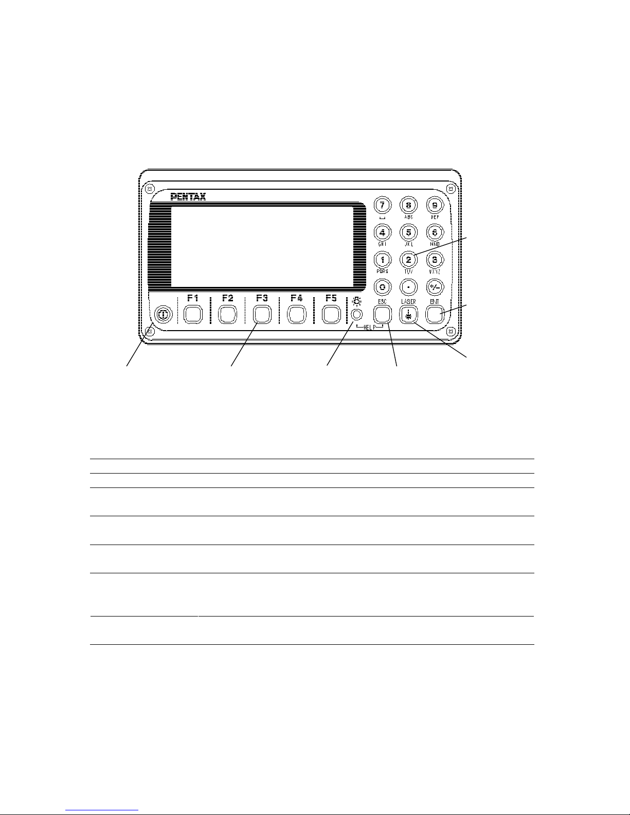
DISPLAY AND KEYBOARD
• Basic display and keyboard of R-400V series are described below, and the function keys of
PowerTopoLite are described in “2. ACCESSING POWERTOPOLITE”.
OPERATION KEY
Key
Description
[POWER]
ON/OFF of power supply.
[ESC]
Returns to previous screen or cancels an operation.
[ILLU]
Turns the illumination of the LCD display and telescope reticle on
and off.
[ENT]
Accepts the selected (highlighted) choice or the displayed screen
value.
[LASER]
Displays the laser plummet and the LD point screen when you push
the Laser key.
[Alphanumeric]
At the numerical value screen, the numerical value and the sign “.”
displayed are input. The English characters printed right under
numeric of each key are input.
[HELP]
Pressing [lLLU]+[ESC] key causes a help menu to appear in
MODE A or MODE B or causes a help message to appear.
Power supply key
Functio n key
Illuminatio n key
ESC key
Laser key
Enter key
Alphanumeric
and +/- key
Page 7

6
FUNCTION KEY
[ ]
F1
Moves the cursor to the left.
[ ]
F2
Moves the cursor to the right.
[ ]
F3
Moves the cursor up.
[ ]
F4
Moves the cursor down.
[ △ ]
F1
Goes back five items on the screen.
[ ▽ ]
F2
Goes forward five items on the screen.
[RETICLE]
F3
Changes the reticle illumination when pressing illumination
key.
[LCD]
F4
Changes the LCD contrast when pressing illumination key.
[ILLU]
F5
Changes the LCD illumination when pressing illumination key.
[CLEAR]
F5
Clears the figure.
[SELECT]
F5
Opens the selection window.
• The Function keys of each PowerTopoLite function are described in
“2. ACCESSING POWERTOPOLITE” and at each function.
Page 8

7
Display combination of MODE A or MODE B
Function
MODE A
MODE B
F1
MEAS
S.FUNC
F2
TARGET
ANG SET
F3
0 SET
HOLD
F4
DISP
CORR
F5
MODE
MODE
• Mode A or Mode B is switched by pressing [F5] [MODE].
ALPHANUMERIC INPUT
The point name etc. is input by the alphanumeric keys as following.
Key
Letter under key
Letter & figure order to input
[0]
[@][.][][-][:][/][0]
[1]
PQRS
[P][Q][R][S][p][q][r][s][1]
[2]
TUV
[T][U][V][t][u][v][2]
[3]
WXYZ
[W][X][Y][Z][w][x][y][z][3]
[4]
GHI
[G][H][I][g][h][i][4]
[5]
JKL
[J][K][L][j][k][l][5]
[6]
MNO
[M][N][O][m][n][o][6]
[7]
[][?][!][][�][^][¦][&][7]
[8]
ABC
[A][B][C][a][b][c][8]
[9]
DEF
[D][E][F][d][e][f][9]
[.][.][,][:][;][#][(][)]
[+/-]
[+][-][*][/][%][=][<][>]
Page 9

8
1. INTRODUCTION
1.1 Introduction
Thank you for your first look at PowerTopoLite by reading this manual.
The PowerTopoLite is a user friendly data collection and calculation program for the
PENTAX R-400V Series Total Stations.
PowerTopoLite is developed based on PowerTopo, which is known as a versatile on-board
software for PENTAX ATS Series Total Stations. The optimum combination of
PowerTopoLite and R-400V hardware makes PowerTopoLite an easy and useful fieldwork
tool.
The icon based main menu offers you the following possibilities.
• FILE MANAGER
• MEASURE
• VIEW AND EDIT
• FREE STATIONING
• STAKE OUT
• CALCULATIONS
• VIRTUAL PLANE MEASUREMENT
• REMOTE DISTANCE MEASUREMENT
• TRAVERSE
• TRANSFER
• PREFERENCE
Page 10
9
1.2 Before using the PowerTopoLite manual
• Memories in the instrument
The R-400V series incorporates not only the PowerTopoLite surveying programs as the
Special Function but also File Manager and Data Transfer Programs.
The internal memory of the instrument can store a maximum of 45.000 points of data.
• Relations between the Memory and each Function
Function Read from the stored data Write to the stored data
Measure SP, BSP SP, BSP, FP (SD)
Stake Out SP, BSP, SOP SP, BSP, SOP, OP
Point to Line SP, BSP, KP1, KP2 SP, BSP, KP1, KP2, OP
Free Stationing Each KP Each KP, SP (CD)
Traverse SP, BSP SP, FP (SD)
VPM SP, BSP, Each KP SP, BSP, Each KP, CP (CD)
Station point:
SP
Foresight
point:
FP
Backsight point:
BSP
Stake Out point:
SOP
Known point:
KP
End point:
EP
Observation
point:
OP
Conversion
data:
CD
Conversion
point:
CP
Crossing point:
CRP
Surveyed data:
SD
Page 11

10
• IH stands for “Instrument Height” and PH stands for “Prism Height”.
• The PowerTopoLite manual mainly describes the R-400V special functions, and the
basic operations are described in the (basic) R-400V manual. Therefore, refer to the R400V basic manual regarding the R-400V general instrument operations.
The PowerTopoLite screens vary with the selections of the “Preference”.
The factory default settings of the Preference are shown there. It is also possible to select
“Process type” that takes over the functionality of “PowerTopoLite” or “Structure type”
that takes over the functionality of our past product in ”Action Method Selection”.
• The R-400V series instrument has a Job name of “PENTAX” and “COGOPoint” as its
default setting. Each data is stored under “PENTAX” unless another new Job name is
created. When another Job name is created, each data is stored in the new Job name.
• The input range of the X, Y and Z Coordinate is “-99999999.998” - “99999999.998”.
• The input range of the Instrument and Prism height is “-9999.999” - “9999.999”.
• The PC, PointCodeList, is added to the PN, Coordinates X, Y, Z and IH (PH or IH) and
you can input your desired attributes for the point. If you have PointCodeList in the job
named “PointCodeList”, you can easily select one of the PointCode from the list or edit
one of them after pressing [ENT]. Please note, that Point Code, which is saved in the
other job, can not be referred to as a list.
• There are two Coordinates types: Rectangular and Polar.
The RO, VO, DO, TO offset and the remote measurement are possible when you select
the
Rectangular Coordinates.
The RO, DO offset is possible when you select the Polar Coordinates.
• When you measure in EDM SETTINGS of COARSE TRACKING, the R-400V displays
a distance value to two decimal places. However, distance data of polar coordinates are
displayed by EDIT function to three decimal places, and sent, to four decimal places. So,
“0“ or “00” is added to the distance data after the third decimal point in COARSE
TRACKING mode.
For example
Displayed value: 123.45
Displayed by EDIT: 123.450
Sent polar data: 123.4500
• Rectangular coordinates are displayed, stored, and sent to three decimal places even if in
COARSE TRACKING or FINE MEASURE mode.
• You can change the distance measurement mode during measuring operation by pressing
the EDM key at the MEASURE and VPM functions.
• The same Point Name of the plural polar points can be saved.
Page 12
11
2. ACCESSING POWERTOPOLITE
2.1 How to access PowerTopoLite
To access the R-400V Special Functions of the PowerTopoLite, perform the following
procedures.
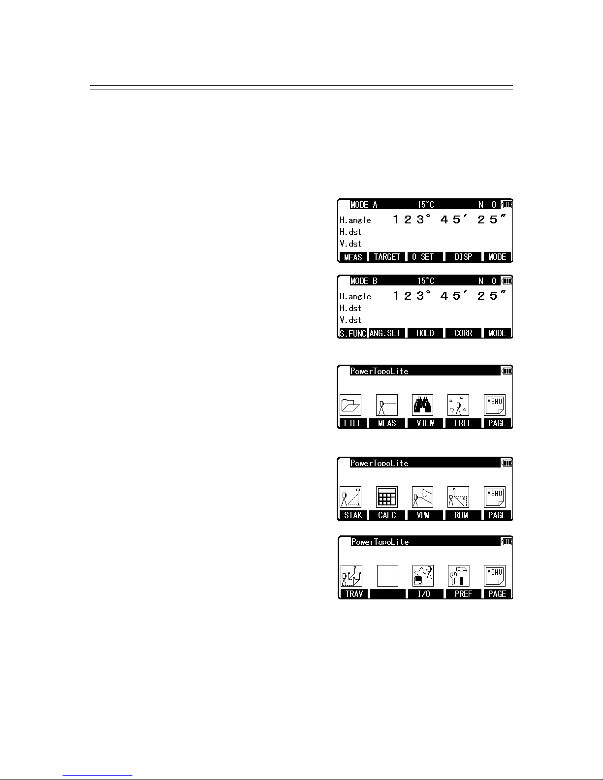
Press the [POWER] (ON/OFF) key to view the R-400V start-up screen.
Then, change to MODE A screen.
Press the [F5] [MODE] to view MODE B screen.
Press [F1] [S.FUNC] to view Functions of
PowerTopoLite screen.
Press [F5] [PAGE] to view another Function
combination of PowerTopoLite screen.
Page 13
12
2.2 Allocation of each PowerTopoLite Function key
PowerTopoLite functions
KEY Function Description
F1 FILE File Manager
F2 MEAS Measure
F3 VIEW View and Edit
F4 FREE Free stationing
Next four Functions are viewed by pressing [F5][PAGE].
KEY Function Description
F1 STAK Stake Out
F2 CALC Calculation
F3 VPM Virtual Plane Measurement
F4 RDM Remote Distance Measurement
Last three Functions are viewed by pressing [F5][PAGE].
KEY Function Description
F1 TRAV Traverse
F3 I/O Input and Output
F4 PREF Preference
INVERSE, POINT COORDINATES, LINE-LINE INTERSECTION functions
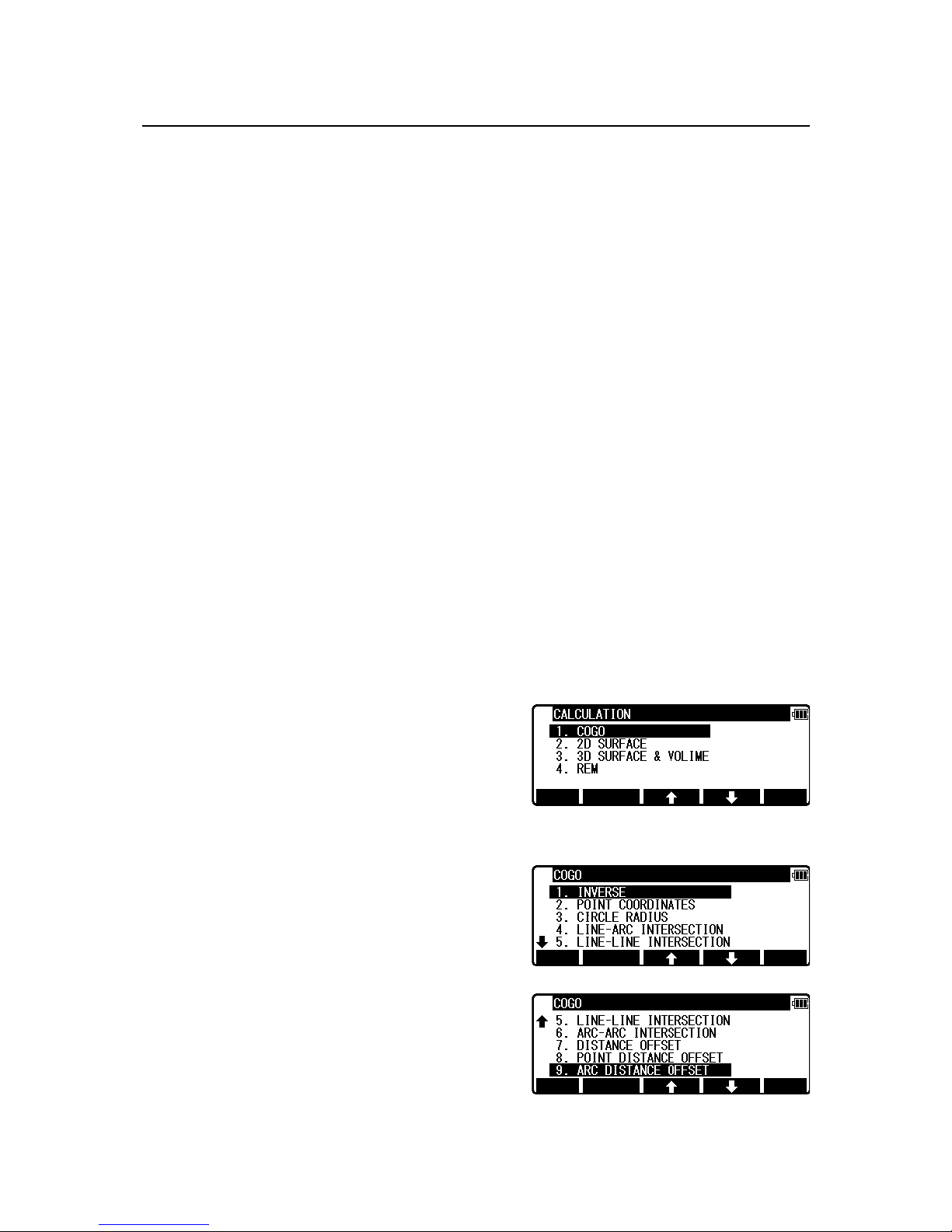
CALCULATION screen is viewed by pressing [F2]
[CALC]. The CALCULATION consists of COGO,
2D SURFACE and 3D SURFACE & VOLUME and
REM functions.
COGO screen is viewed by selecting 1. COGO and pressing [ENT].
The COGO consists of INVERSE,
POINT COORDINATES,
CIRCLE RADIUS,
LINE-ARC INTERSECTION,
LINE-LINE INTERSECTION,
ARC-ARC INTERSECTION,
DISTANCE OFFSET,
POINT DISTANCE OFFSET,
ARC DISTANCE OFFSET,
and functions.
Page 14

13
2.3 Typical Function keys of PowerTopoLite
Following function keys are typical of PowerTopoLite and each function key is described for
each function in this Manual.
KEY
Description
PAGE
Views another function combination.
SELECT
Selects the Character and moves to next input at PN input etc.
ACCEPT
Enters the displayed values without new Coordinates value input etc.
INPUT
Inputs your desired Horizontal angle.
BSP
Views the BSP SETUP screen to input its Coordinates.
SAVE
Saves input data.
ME/SAVE
Measures and then saves input data.
EDIT
Changes the Point Name or Prism Height.
REMOTE
Views your aiming point Coordinates.
OFFSET
Views the Target Coordinates adding the offset values.
STATION
Returns to the STATION POINT SETUP screen.
H. ANGLE
Returns to the STATION POINT H.ANGLE SETUP screen.
LIST
Views the POINT SELECTION FROM THE LIST screen.
OTHER
Views the JOB LIST SEARCH screen.
ZOOM ALL
Returns to the original size.
ZOOM IN
Magnifies the graphics size.
ZOOM OUT
Reduces the graphics size.
DRAW
Views the GRAPHICAL VIEW screen.
DISP
Views point or point & graphic or point & point name or all.
DELETE
Views the POINT DELETION screen.
FIND PN
Views the PN search screen by inputting the point name.
ADD
Allows you to add more points for free stationing.
CALC
Starts the calculation of free stationing.
NEXT
Views the next known point Coordinates setup screen.
DATA
Views the TARGET POINT screen.
TARGET
Selects the Target type.
EDM
Selects the EDM settings.
ALL
Selects all points of the current job.
ORDER
The order of selected points.
Page 15
14
3.FILE MANAGER
The Data storage memory status, Creating a new Job Name and the Selection
and Deletion of a Job Name is executed by this function.
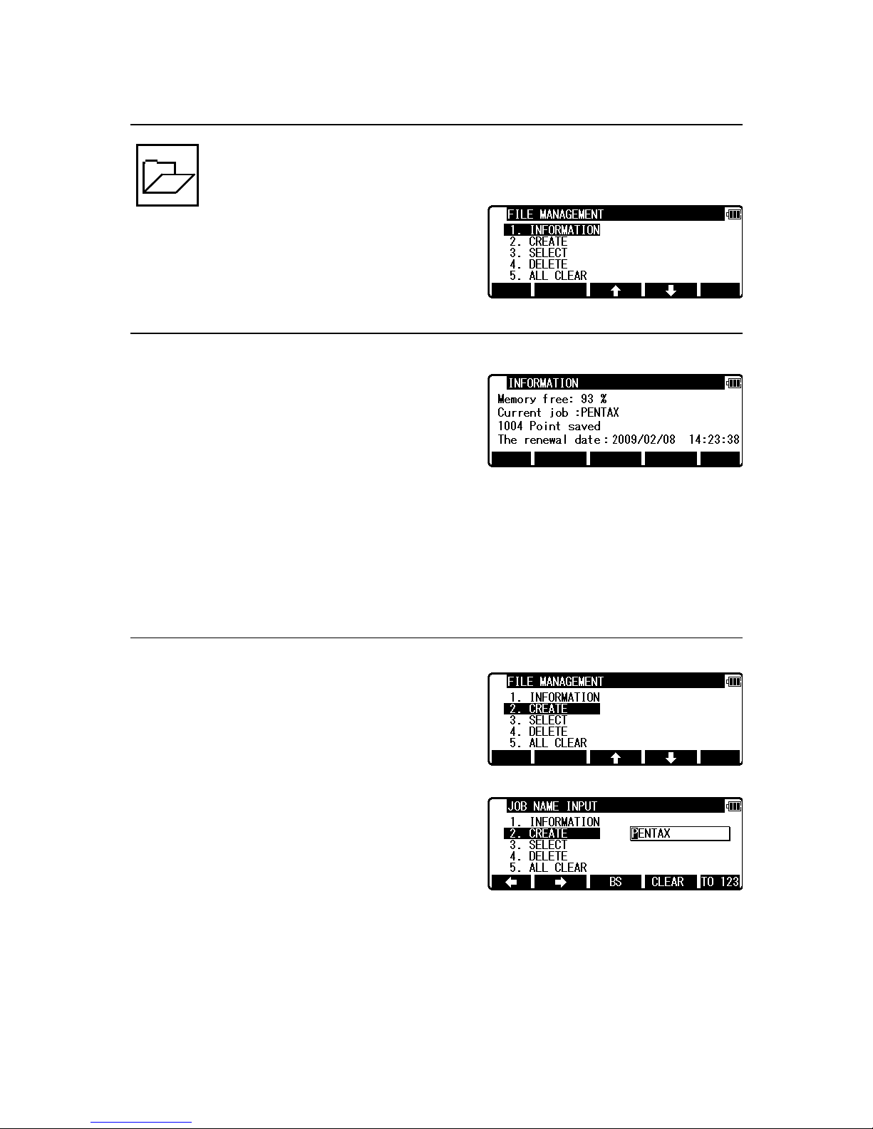
From the PowerTopoLite screen, press [F1] [FILE]
to view the FILE MANAGEMENT screen.
3.1 Information of the remaining memory availability
Press [ENT] to view INFORMATION screen.
The remaining memory availability and a JOB Name PENTAX are viewed on the screen.
The Job name “PENTAX” and “COGOPoint” are a default setting.
NOTE: Data being used in COGO will be updated in “COGOPoint” file from time to time.
For more details, refer to “8.1 COGO”
3.2 Creation of a new Job
Select 2. CREATE by the down arrow key.
Press [ENT] to view the JOB NAME INPUT screen.
• The Job Name input method can be selected by the “Input method selection” of the
“Preference”. This is the “10 KEY SYSTEM” input selection.
• If a new Job is created, the new data is stored in this new Job.
Page 16
15
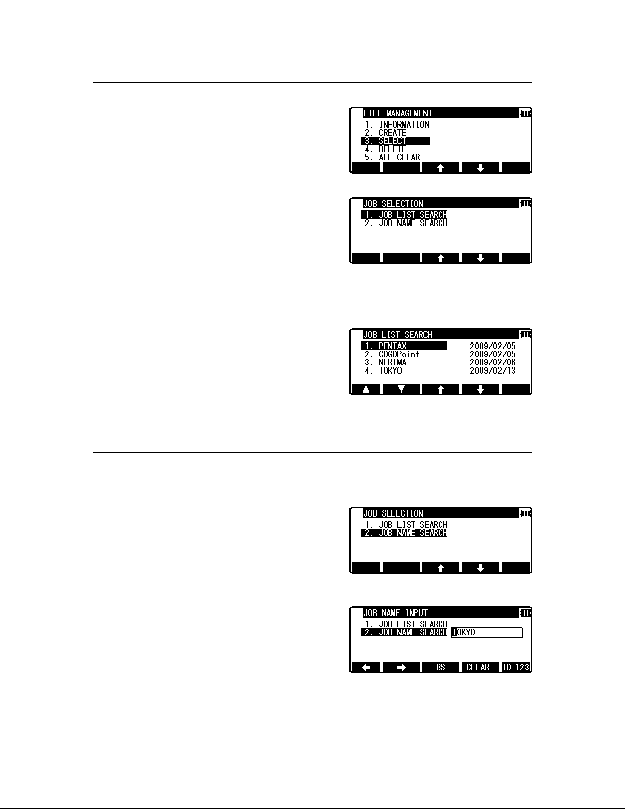
3.3 Selection of a Job Name
Select 3. SELECT by pressing the down arrow key.
Press [ENT] to view the JOB SELECTION screen.
3.3.1 Selection of a Job
Select 1. JOB LIST SEARCH and press [ENT] to
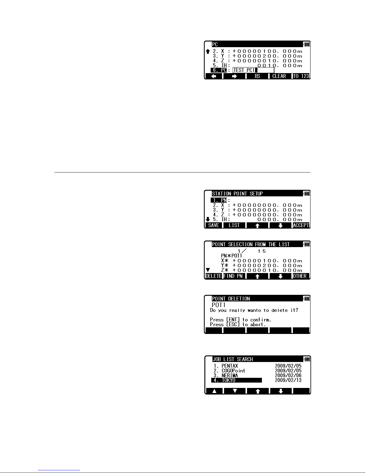
view its screen.
JOB LIST is a list of all stored Jobs.
Select your desired Job Name and press [ENT] to select.
3.3.2 Selection by a Job Name input
Select 2. JOB NAME SEARCH by pressing the down arrow key.
The JOB NAME SEARCH is the search by inputting
your desired Job Name.
Press [ENT] to view the JOB NAME INPUT screen.
Page 17
16
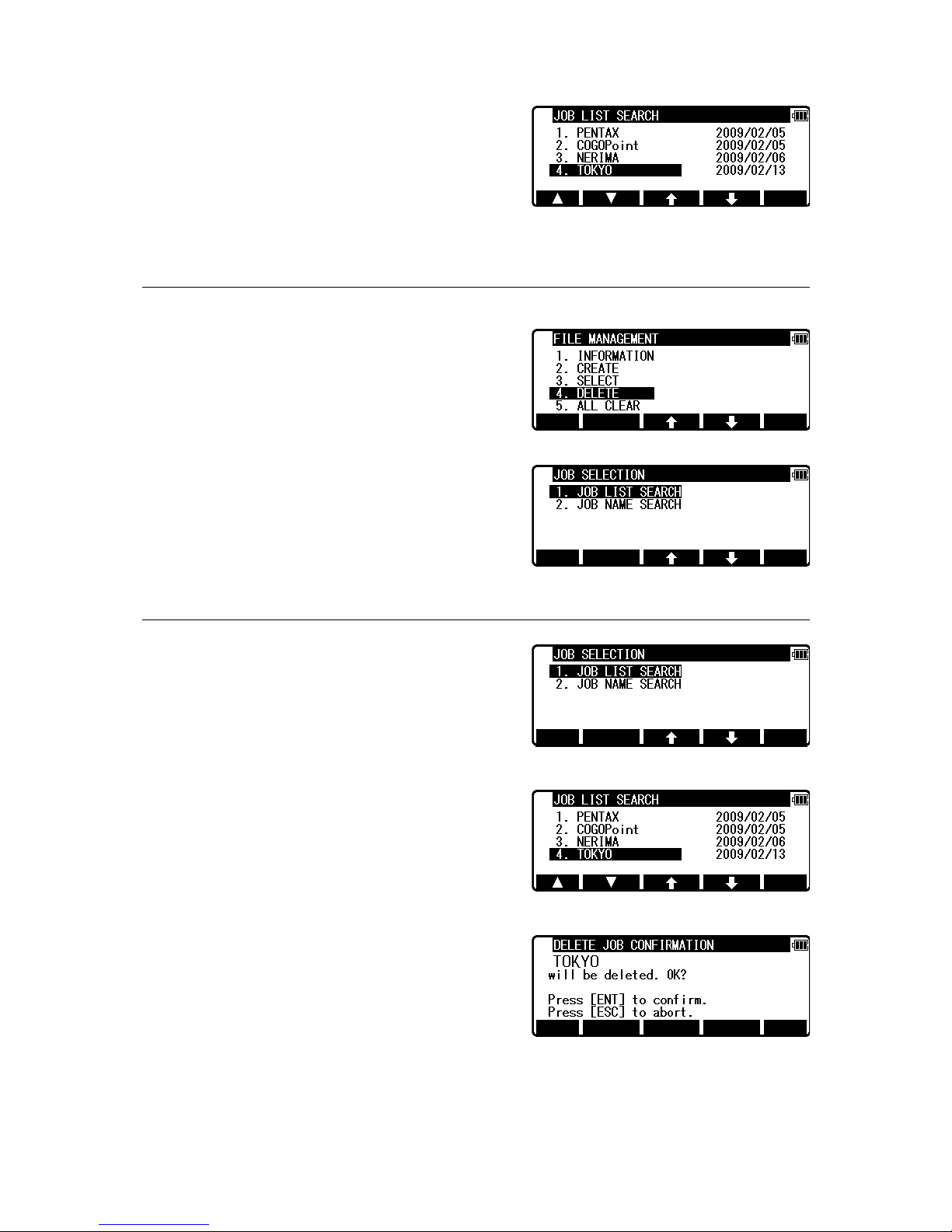
Input your desired JOB NAME and press [ENT] to
view the JOB LIST SEARCH screen.
Press [ENT] to select this.
3.4 Deletion of a Job Name
Select 4. DELETE by pressing the down arrow key.
Press [ENT] to view the JOB DELETION screen.
3.4.1 Deletion from a Job List
Select 1. JOB LIST SEARCH and Press [ENT] to
view its screen.
If TOKYO is selected, deletion confirmation screen
is viewed.
Press [ENT] to delete or [ESC] to abort.
Page 18
17
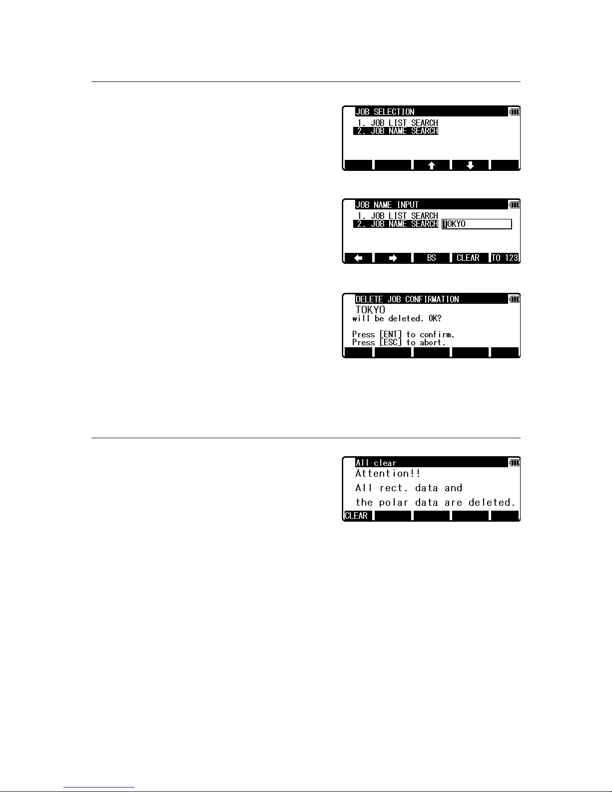
3.4.2 Deletion from a Job Name search
Select 2. JOB NAME SEARCH by pressing the
down arrow key.
Press [ENT] to view the JOB NAME INPUT screen.
Input your desired JOB NAME to delete and press
[ENT] to view the DELETE JOB CONFIRMATION
screen.
Press [ENT] to delete or [ESC] to abort.
The R-400V series has a Job Name “PENTAX” as its default setting.
Therefore, each data is stored in “PENTAX” unless another new Job Name is
created. When another Job Name is created, each data is stored in the new Job Name.
3.5 All Clear
Select 5. All Clear by pressing the down arrow key.
Press [ENT] to view its screen.
Warning: When [CLEAR] is pushed, all Job Files are deleted.
NOTE: - Creating several new JOB Files and writing-in or rewriting data on the same
JOB Files repeatedly may cause the time of writing-in and rewriting of the data to be
slower.
- Saving data when the memory capacity is almost full, and then deleting some JOB
Files in order to secure open memory capacity, may cause the time of writing-in and
rewriting the data to be slower.
- In case the time of writing-in or rewriting the data becomes slower, send
the necessary data to PC for backup, then enter ‘All Clear’ in FILE MANAGER.
The above procedure will format the inside memory automatically and improve the time
of writing-in and rewriting the data. Beware that all JOB Files will be deleted.
Page 19
18
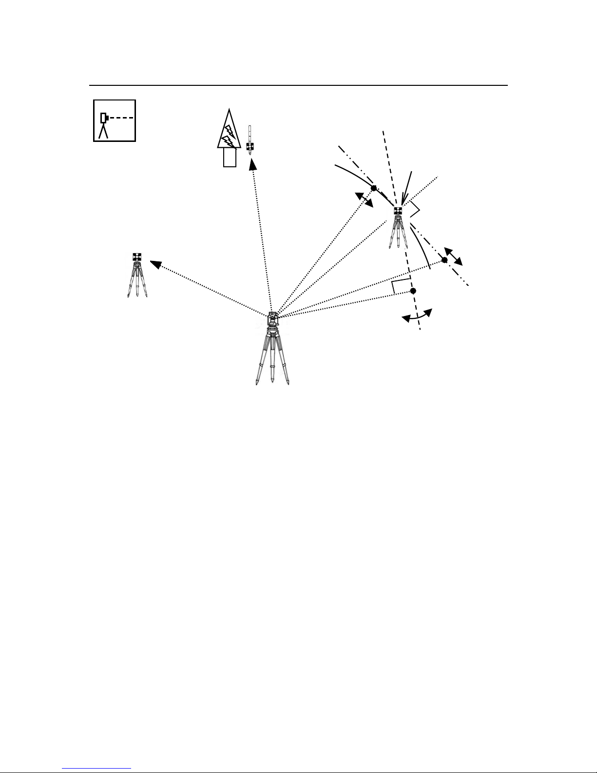
4. MEASURE
An operator can measure the Foresight Point Coordinates from the “Station Point Coordinates
and Backsight Coordinates” or the “Station Point Coordinates and Azimuth”, and can store
the Point Name and measured Coordinates in the memory. When the Coordinates of the
Station Point and Backsight Point are already stored in the memory, the new Coordinates
input can be omitted by calling or searching from the Point Name LIST.
The Point Name is within 15 characters and the Coordinates are within 8 in integer and 3 in
decimal number. There are two Coordinates types: Rectangular and Polar Coordinates in this
[MEASURE].
The Offset at the Target Point Measurement is possible and the Remote Measurement, by
aiming at any point, is possible as well when you select the Rectangular Coordinates.
An operator can perform the [MEASURE] function only when the Telescope is at the “Face
left position”.
Select the Target type before performing the [MEASURE].
After measuring rectangular coordinates by [MEASURE] function of PowerTopoLite, it is
possible to display Angle and Distance by switching the [F3][ANG&DIST] key.
When Remote Mode is selected, Angle and Distance are also calculated according to the
Coordinates of the Aiming Point on real time.
When offset mode is selected, Angle and Distance are also calculated according to the
Coordinates where offset value is added.
Backsight P. Coordinates
Azimuth
Reference P. Coordinates
1.Cylinder face
2.Fixed plane
3.Rotated plane
Station Point Coordinates
Offset
Remo te
Page 20
19
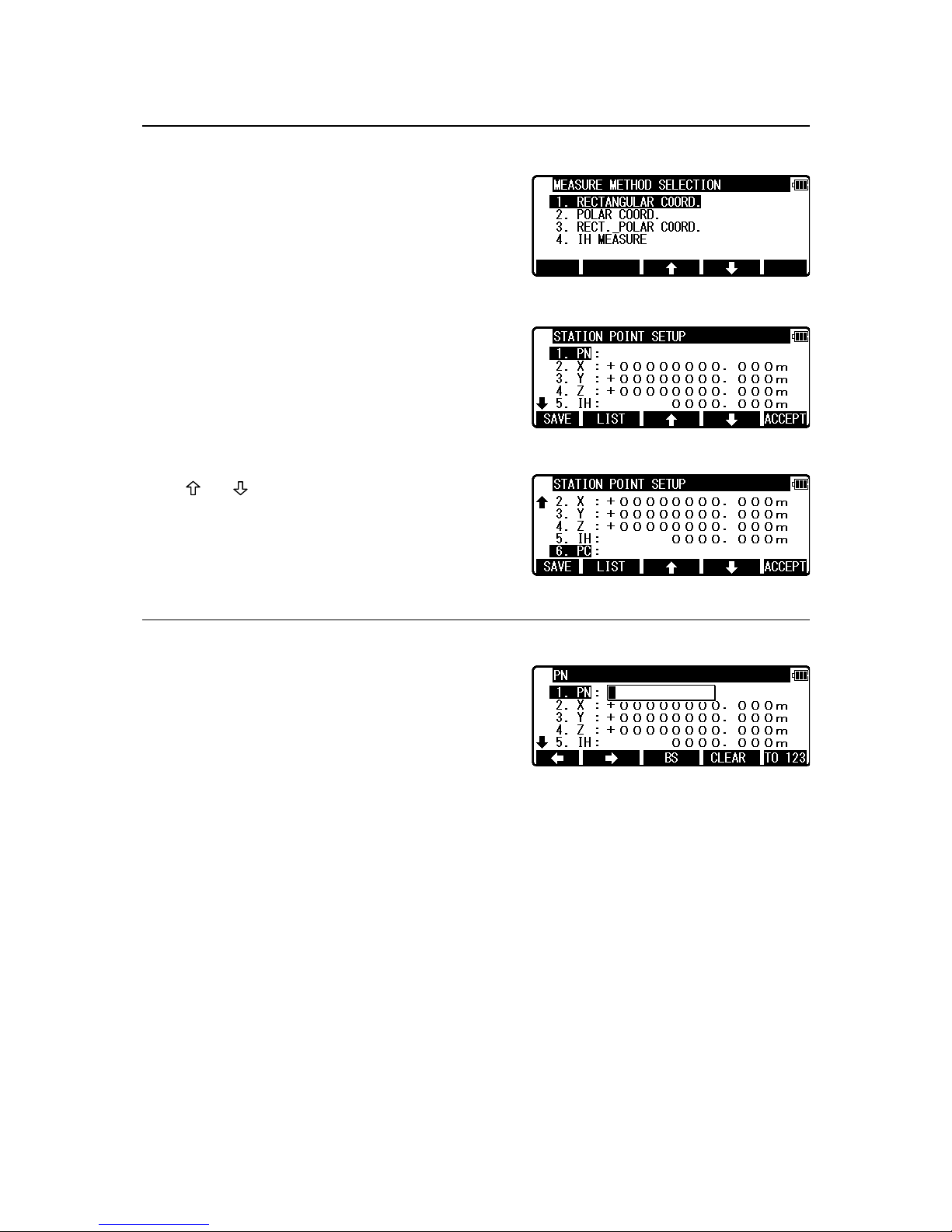
4.1 Station setup [By Rectangular Coordinates]
Press [F2] [MEAS] of the PowerTopoLite to view
the MEASURE METHOD SELECTION screen.
Select 1.RECTANGULAR COORD. and press
[ENT] to view the STATION POINT SETUP
screen.
The [ ] / [ ] mark is used to scroll up / down.
“6. PC” is viewed by scrolling down.
4.1.1 Point Name input
Select 1. PN to display the PN input screen.
[ENT] is used for both accepting the selected choice
and opening the input screen of the Coordinates
values, etc.
Input your desired point name by pressing keys, and after all Characters are input,
press [ENT].
Four character selection methods are available. (Refer to the “13.3 Input method selection”)
Page 21
20
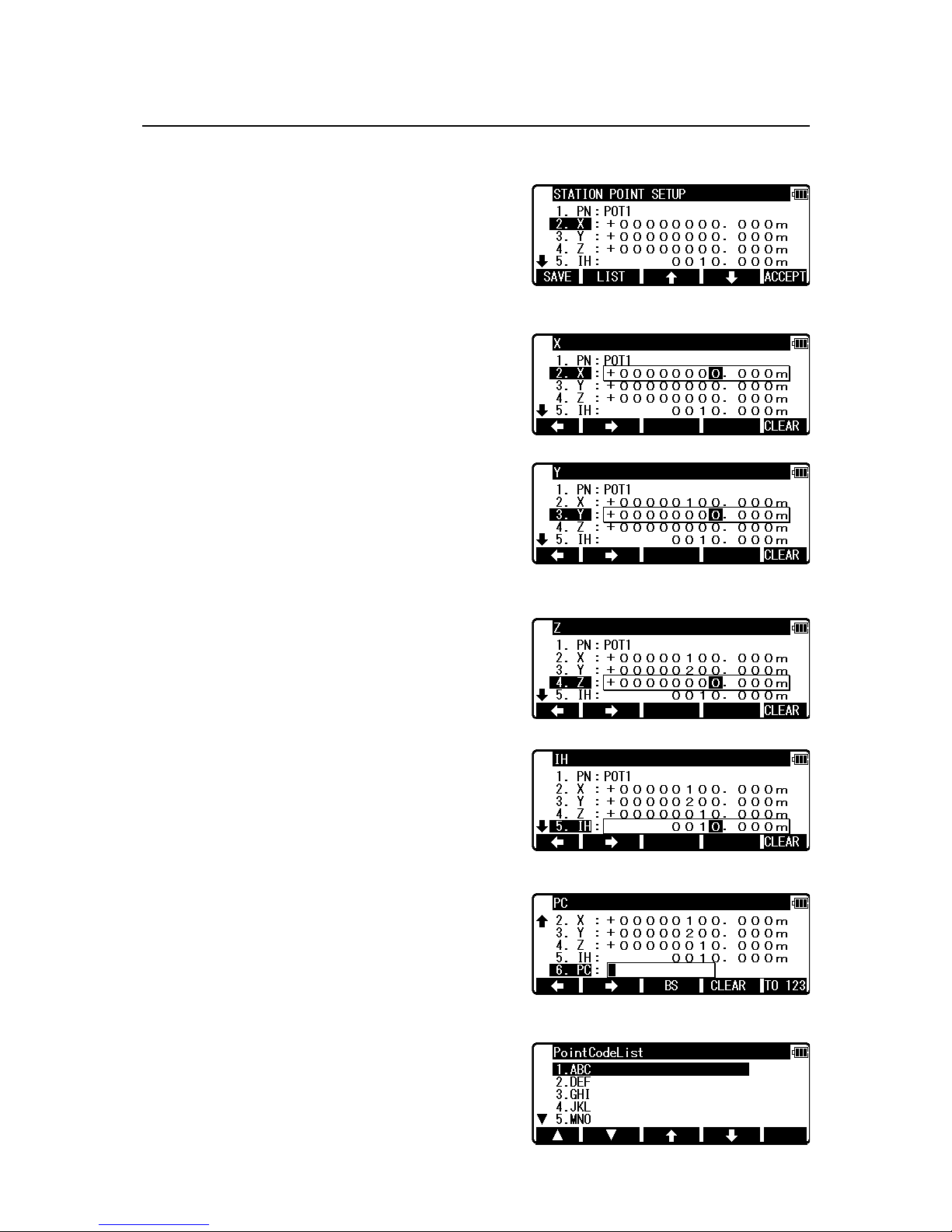
4.1.2 Coordinates, X, Y, Z, IH, and PC input
It goes to 2. X coordinate automatically.
Press [ENT] to view the X coordinate input screen.
Input X, Y and Z coordinates, IH and PC as follows.
Input your desired X coordinate value by pressing
keys.
Y coordinate:
Press [ENT] to view the Y coordinate input screen.
Input your desired Y coordinate value
by pressing keys.
Z coordinate:
Press [ENT] to view the Z coordinate input screen.
Input your desired Z coordinate value
by pressing keys.
IH value:
Press [ENT] to view the IH screen. Input your
desired IH value by pressing keys.
PC, Point Code:
Press [ENT] to view and input the PC screen.
If Point Code exists, you can easily select it from the
list.
For using PointCodeList, please refer to “5.4.1 Point
Code”.
Page 22
21
After pressing [ENT], you can edit Point Code data.
Input your desired PC name by pressing keys, and press [ENT] to view next screen.
If “PROCESS TYPE” is selected in “Action method selection”, after input/confirm PC data,
the input POT1 data will automatically be stored in the memory. Then the panel
“STATION POINT H.ANGLE SETUP” will be displayed.
But, if “STRUCTURE TYPE” is selected in “Action method selection”, it is necessary to
press [ACCEPT] to proceed to next panel.
4.1.3 Point selection from the list
Inputting coordinate information can be done
manually and also by calling known points.
Press [F2] [LIST] on STATION POINT SETUP
screen to display POINT SELECTION FROM THE
LIST screen
• [DELETE] Key
To delete the points being displayed
Press [F1] [DELETE] to display
POINT DELETION screen.
Press [ENT] to delete the selected point from job file.
Press [ESC] to return STATION POINT SETUP.
• [OTHER] Key
To select the Job File to be listed
Press [F5] [OTHER] to display JOB LIST SEARCH screen, then select the Job File.
Page 23
22
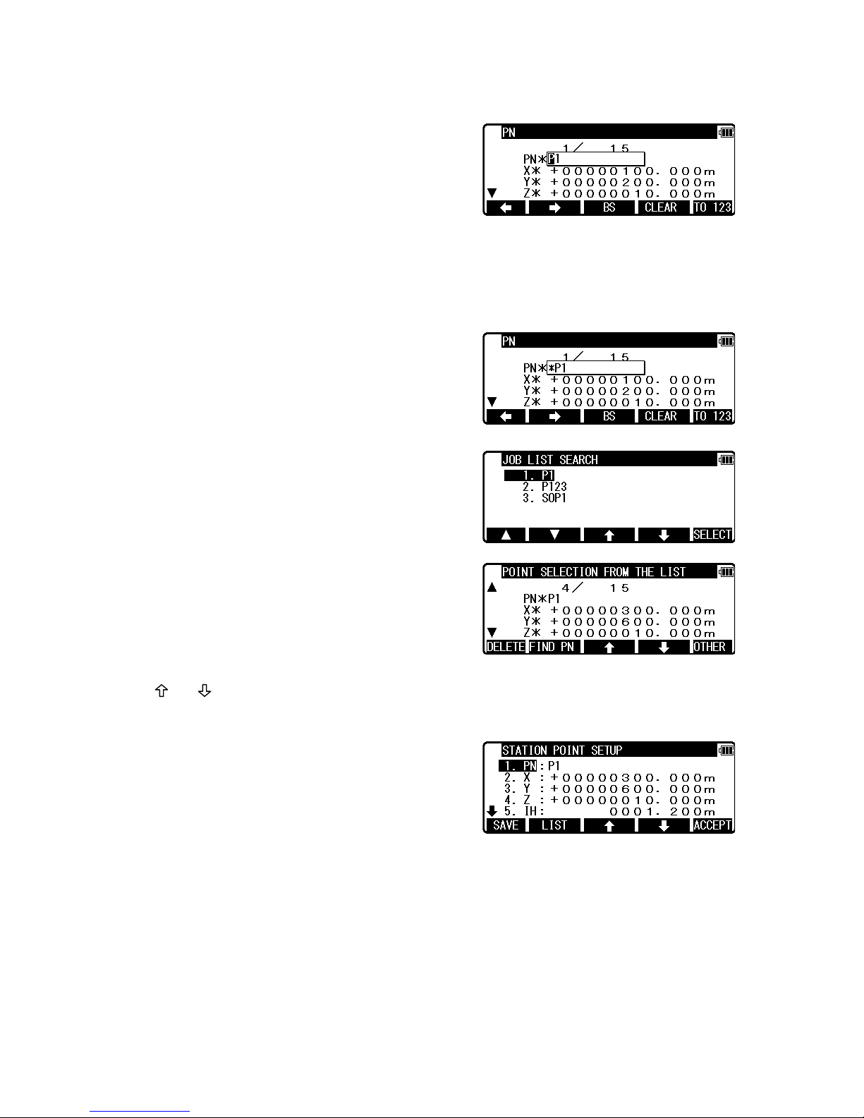
• [FIND PN] Key
To search PN from key word
Press [F2] [FIND PN] to display PN input screen,
then input key word.
NOTE: Searching a point by adding “* ” to the initial of the key word enables you to list
point data with PN including a string after “*”
For instance, if you need to search a point
including “P1” in PN, input “*P1” in the key
word, then press [ENT].
Select the point from the list
Press [ENT] to display the point that matches the
key word.
• [ ] / [ ] Key
To switch to the point to be displayed.
When the point you want is displayed,
press [ENT] to finalize input.
Page 24
23
4.2 Station Orientation
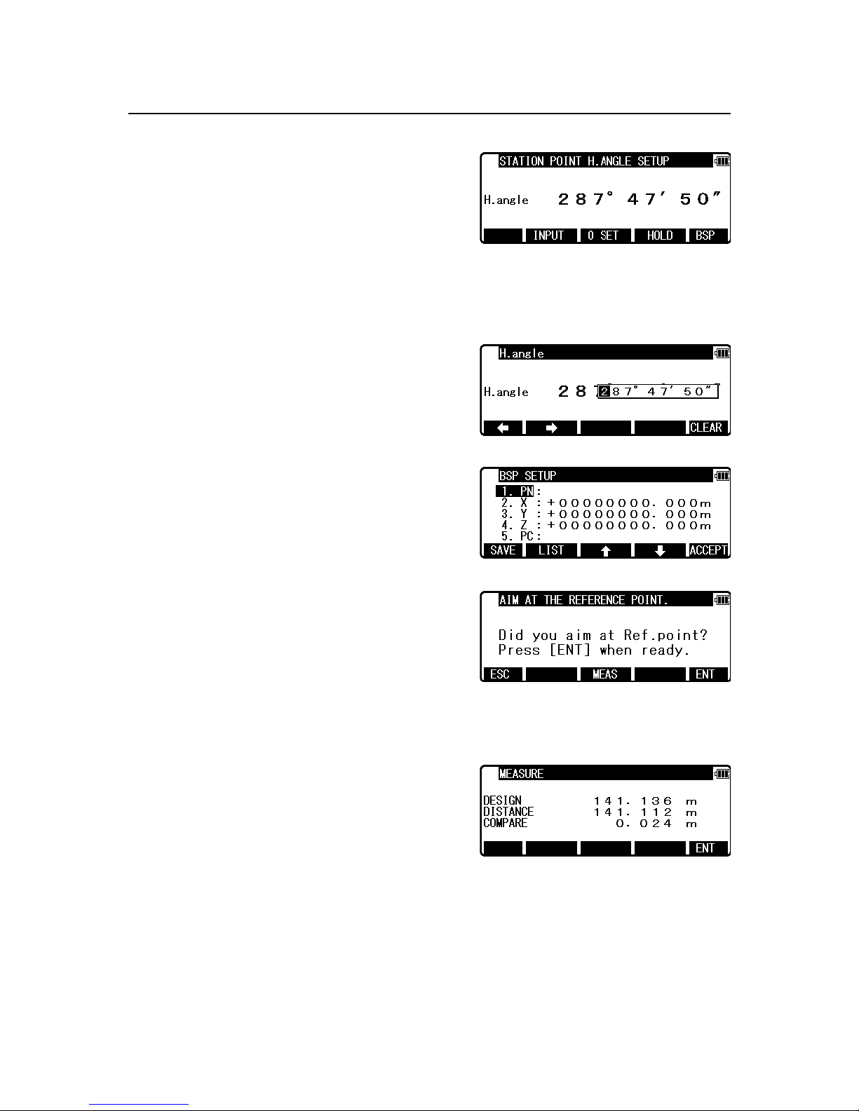
Press the [F5] [ACCEPT] to view the STATION
POINT H.ANGLE SETUP screen.
Please note, that the rotation of the “H.angle”
depends on the rotation setting of
“Coordinate axis definition”.
Input the H.angle by pressing [F2] [INPUT], [F3] [0SET] and [F4] [HOLD] or Reference
Point Coordinates by pressing [F5] [BSP].
• [INPUT] Key
Enter any horizontal angle.
Press [ENT] to view the BSP SETUP screen.
• [BSP] Key
The Back Sight Point information is obtained.
Press [ENT] to finalize input.
Press [ENT] or [F5] [ACCEPT] to view the AIM
AT THE REFERENCE POINT screen.
Press [F5] [ENT] to finalize BSP.
Press [F1] [ESC] to redo input.
If you want to make measure to check
the point to be aimed, press [F3] [MEAS] to display MEASURE screen.
Press [F3] [MEAS] to make the distance
measurement. DESIGN DISPLAY screen
appears when the distance measurement is done.
Compare design value with measured value.
When “PREFERENCE” of “12. BOTH FACES MEAS” is on, measure the distance at the
normal and reverse position.
The measured value to be displayed is the average of measured values measured in normal
and reverse position.
Page 25
24
4.3 Multiple Orientation
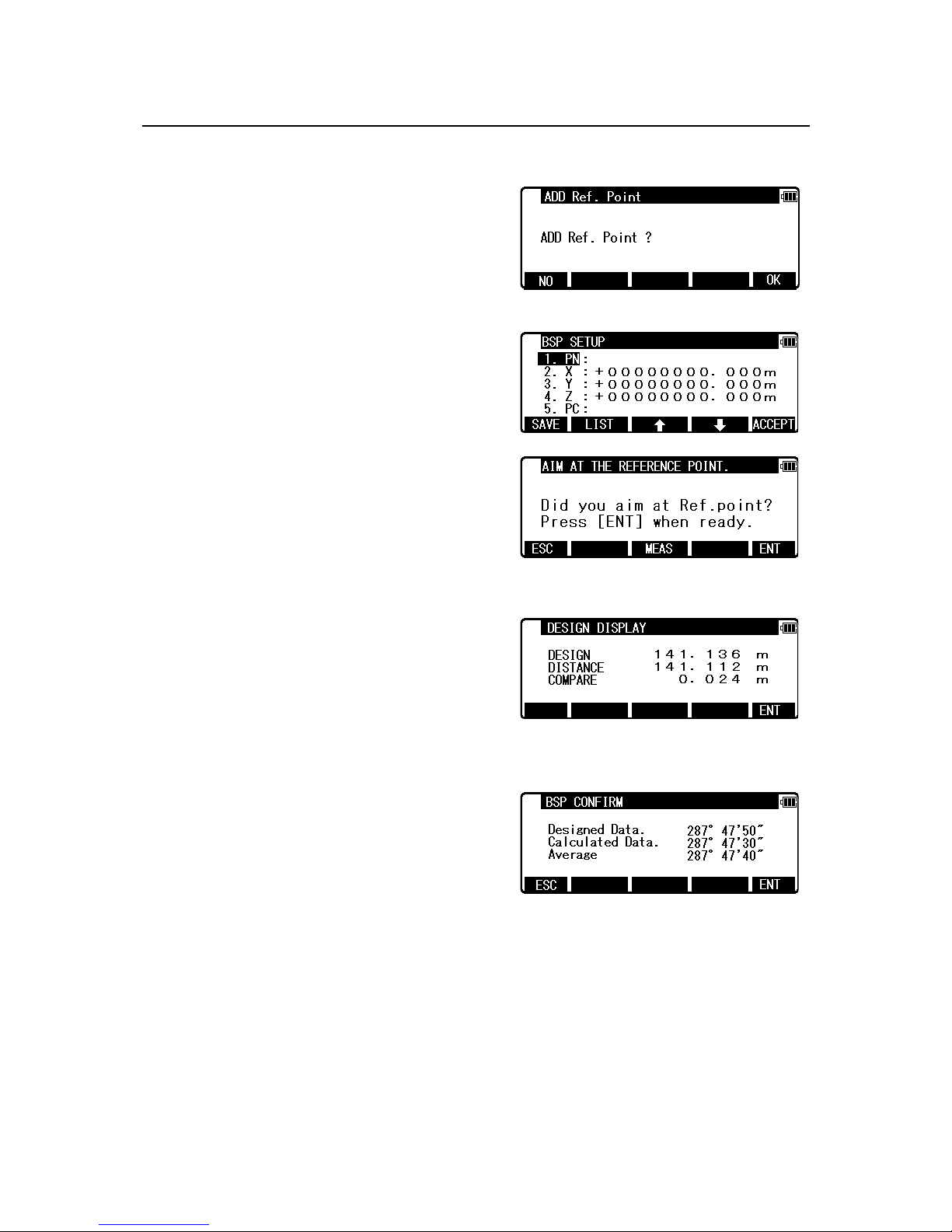
Aim at the reference point , then press [ENT] to
enter Multiple Orientation.
Pressing [F1] [NO] of “ADD Ref. Point screen
immediately takes you to 4.4 measure screen.
Pressing [F5] [OK] goes to BSP SETUP screen.
The same procedure as mentioned in “4.2 Station
Orientation” will proceed.
Press [F3] [MEAS] to go to BSP CONFIRM.
Pressing [F5] [ENT] takes you to DESIGN
DISPLAY
Designed Data: the present angle according to the
first orientation.
Calculated Data: the calculated data according to
the second orientation.
Average: the average value of designed data and
calculated data.
ESC: The present angle doesn't change.
ENT: The present angle is changed to the calculated data.
Page 26
25
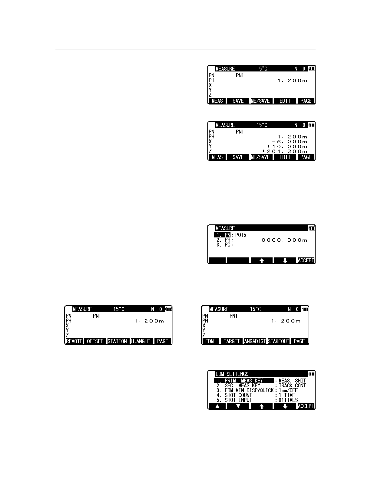
4.4 Function of MEASURE screen
Press [ENT] to display the MEASURE screen
Press [F1] [MEAS] to measure the Distance and
display the Coordinates.
Press [F2] [SAVE] to save the measured data.
Press [F3] [ME/SAVE] to measure and save the measured data.
The survey data is not saved if no PN is input.
Press [F4] [EDIT] to edit the PN, Point Name, PH, Prism Height and PC, Point Code.
Input your desired Point Name, Prism Height and Point Code.
Press [F5] [ACCEPT] if the current PN, PH and
PC are acceptable.
If Point Code exists, you can easily select them
from the list or edit one of them after
pressing [ENT]. For using Point Code List, please
refer to “5.4.1 Point Code”.
Press [F5] [PAGE] to view another menu.
EDM settings can be selected by pressing [F1]
[EDM].
For example, change 1.PRIM. MEAS KEY (MEAS)
to TRACK SHOT or TRACK CONT if you want to
use tracking measurement with primary MEAS key
(MEAS).
The target type can be selected by pressing [F2] [TARGET].
Page 27
26
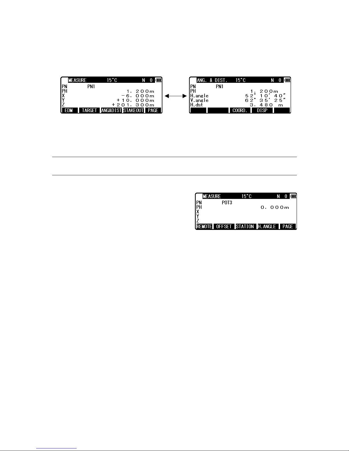
Coordinates display and Angle & Distance display
1) Press [F5] [PAGE] twice to view [F3] [ANG & DIST].
2) Press [F3] [ANG & DIST] to view [F3] [COORD.] and Angle and Distance values.
3) Press [F3] [COORD.] to view [F3] [ANG&DIST] and Coordinates.
Stake Out can be selected by pressing [F4] [STAKEOUT].
4.5 Remote, Offset, Station, and H. angle function
4.5.1 Remote
Press [F5] [PAGE] to view another MEASURE
menu.
Press [F1] [REMOTE] once and then quickly press
this key again to measure your desired point
Coordinates by moving the telescope.
The displayed Coordinates automatically change according to your aiming point.
The Remote is a function of, so to speak, “Real-time offset”. If a reference point or offset
point is measured, the Coordinates of your aiming point are calculated based on the reference
plane.
There are three calculation methods: Cylindrical face, Fixed plane and Rotated plane.
They are selected by “13. Preference”. Refer to “13.5 Remote method selection”.
The calculations are performed on the virtual planes.
To quit the Remote measurement, press [F1] [REMOTE] twice again.
Page 28
27
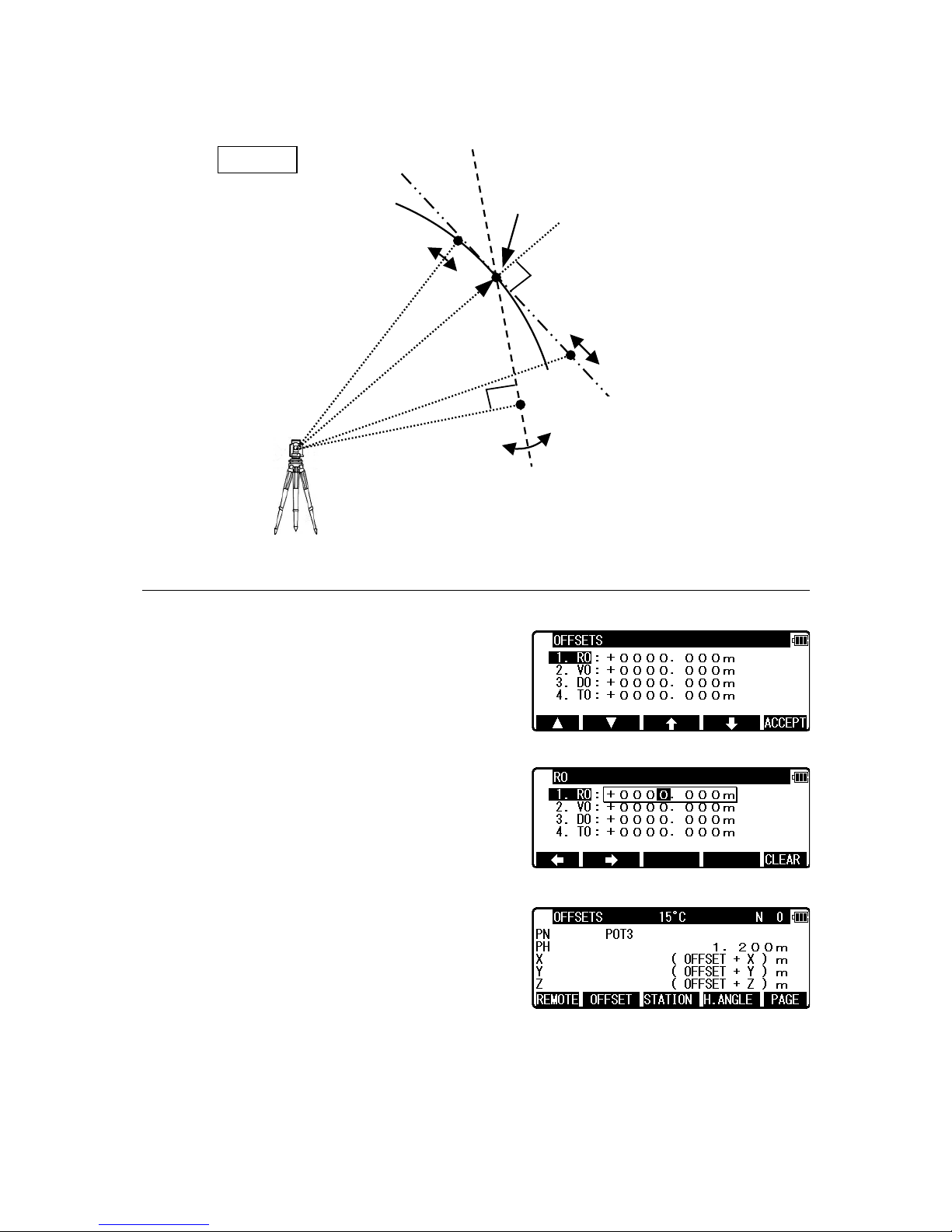
4.5.2 Offset
Press the [F2] [OFFSET] to view the OFFSETS
screen.
Offset enables you to work with Offsets.
The following offsets are available.
Press [ENT] to view the offset input window.
Input the RO offset value by pressing keys.
VO, DO and TO values are input in the same
manner.
After input “TO” value, press [ENT] to view the
MEASURE screen.
(Or press [ESC] then press [ACCEPT].)
The offset values are added to X, Y and Z values.
The input value of Offset is cleared when you save the surveying point and step forward
to the next surveying point.
1.Cylinder face
Reference P. Coordinates
2.Fixed plane
3.Rotated plane
Station Point Coordinates
REMOTE
Page 29
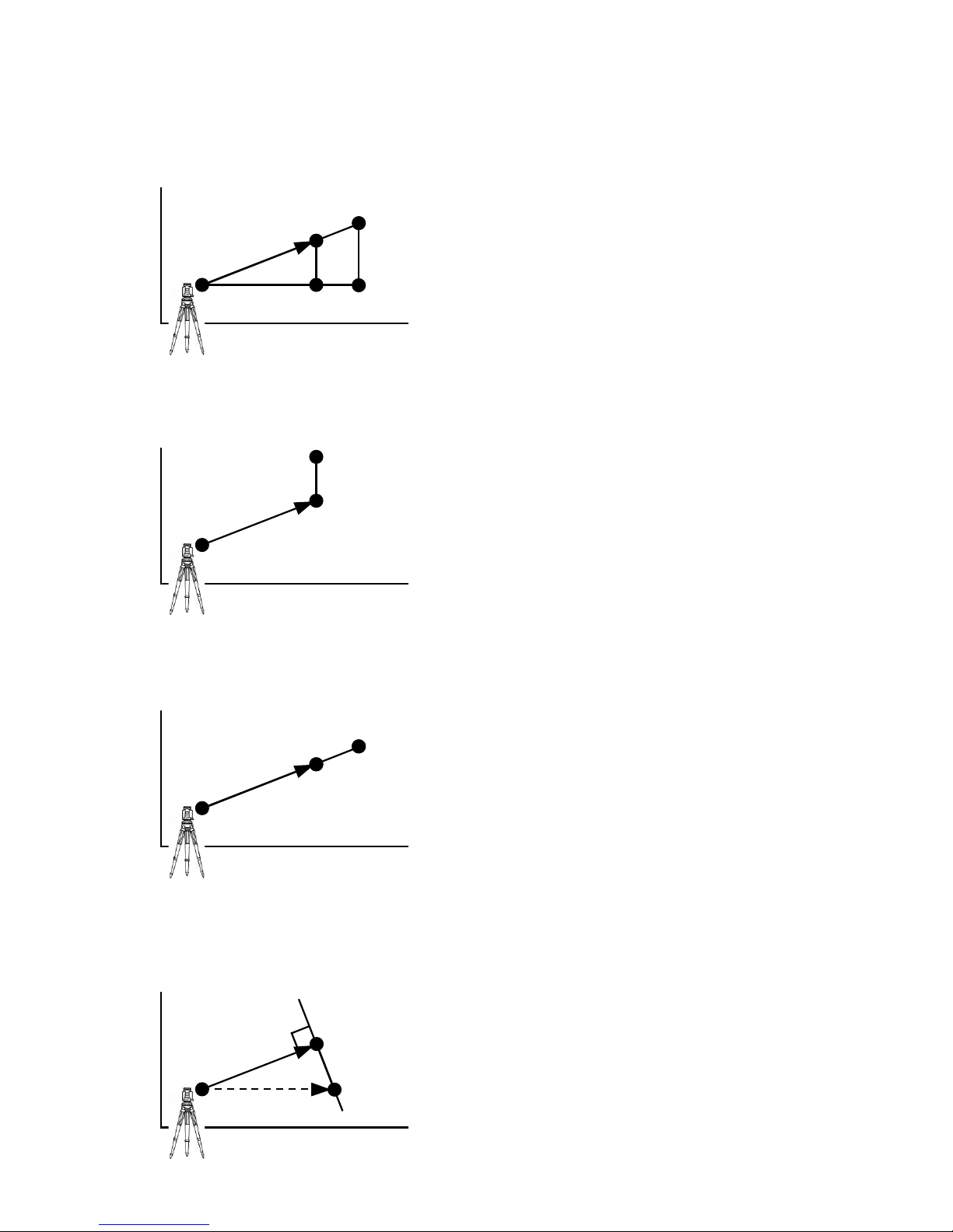
28
RO: Radial Offset
(RO: On the horizontal plane. Offset P: Along the line of measurement, thus along the slope)
VO: Vertical Offset (Along the third axis)
DO: Distance Offset (Along the line of measurement, thus along the slope)
TO: Tangential offset (TO: On the horizontal plane, perpendicular to the horizontal line
between Station and Point. Offset P: Along the slope)
Z
SP
RO
Offset Poin t : Offset P
X.Y
P Z SP
VO
Offset P
X.Y
P Z SP
DO Offset P
X.Y
P
X
SP
TO
Offset P
Y
P
Page 30
29
4.5.3 Station
Press [F3] [STATION] to return to STATION
POINT SETUP screen.
4.5.4 H. angle
Press [F4] [H.ANGLE] to return to STATION
POINT H. ANGLE SETUP screen.
Press [ENT] to view the MEASURE screen.
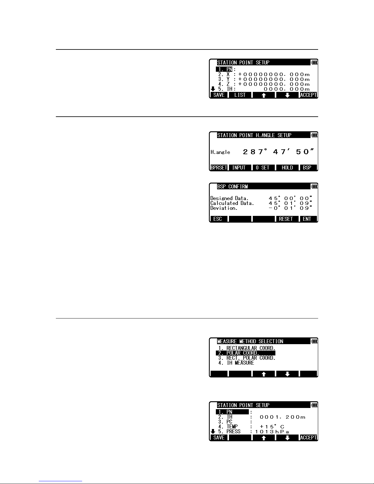
• [BPRSET] key
Deviation of Back Sight Point can be seen.
Press [F1] [BPRSET] key to display BSP
CONFIRM screen.
“Designed Data” represents the horizontal angle of the current Back Sight Point.
“Calculated Data” represents the horizontal angle of the direction that R-400V is facing.
“Deviation” represents deviation of “Calculated Data”.
If you accidentally move the instrument during the measurement, the amount of error can
be checked on this screen.
If the instrument is significantly moved, press [F4] [RESET] to reset Back Sight Point at
the current position.
If the amount of error is small, press [F5] [ENT] to return to MEASURE screen.
4.6 Station setup [By Polar Coordinates]
The same Point Name of the plural polar points can
be saved.
Press [F2] [MEAS] of the PowerTopoLite screen to
view the MEASURE METHOD SELECTION
screen.
Select 2. POLAR COORD. and press [ENT] to view
the STATION POINT SETUP screen.
Page 31

30
The [ ] / [ ] mark is used to scroll up / down.
4.6.1 Point Name input
Select 1.PN to display PN input screen.
Input PN value.
Press [ENT].
4.6.2 IH, TEMP, PRESS, ppm and PC input
Input IH value.
Press [ENT].
Input the PC.
Press [ENT] to view and input the PC, Point Code,
screen.
If Point Code exists, you can easily select it from the
list or edit one of them after pressing [ENT].
For using Point Code List, please refer to “5.4.1
Point Code”.
Whichever you select PROCESS TYPE or STRUCTURE TYPE,
Pressing [SAVE] or [ACCEPT] proceeds to next screen
Input the TEMP value.
Press [ENT].
Input the PRESS value.
Press [ENT].
Page 32

31
Input ppm value.
Press [ENT].
TEMP, PRESS and ppm input depend on the “Initial setting 1”
(ATM INPUT, ppm INPUT, NIL).
4.7 Station Orientation
Press the [F5] [ACCEPT] to view the STATION
POINT H. ANGLE SETUP screen.
Input your desired H.angle.
• [INPUT] key
Input your desired H.angle.
Please note, that the rotation of the “H.angle”
depends on the rotation setting of
“Coordinate axis definition”.
• [INVERS] key
If you want to calculate direction angle, Press
[F5][INVERS] to jump to INVERSE function.
Input SP as Station Point, EP as Back Sight Point.
Result angle is set here automatically by pressing
[ENT] at RESULT OF INVERSE screen.
Press [ENT] after aiming back sight point.
Aim at the reference point, then press [ENT] to enter
multiple orientation. For more details, refer to “4.3
Multiple Orientation”. After the multiple orientation
is completed, the screen moves to MEASURE
screen.
Page 33

32
4.8 Function of MEASURE screen
Aim at the reference point and press [ENT] to view
the MEASURE screen.
Press the [F1] [MEAS] to measure and display the
Distance.
Press [F2] [SAVE] to save the measured data.
Press [F3] [ME/SAVE] to measure and save the measured data.
No survey data is saved when no PN is input.
Press [F4] [EDIT] to edit the PN, Point Name, PH,
Prism Height and PC, Point Code.
Press [ENT] to view each input window by pressing
up or down arrow key, and input your desired point
name or prism height or point code.
Press [F5] [ACCEPT] if the current PN, PH and PC
are acceptable.
PC, Point Code:
Press [ENT] to view and input the PC, Point Code, screen.
If Point Code exists, you can easily select them from the list or edit one of them after pressing
the [ENT]. For using PointCodeList, please refer to“5.4.1 Point Code”.
Press [F5] [PAGE] to view another menu.
Station point setup can be changed by pressing [F3]
[STATION].
Page 34

33
EDM settings can be selected by pressing [F1]
[EDM].
For example, change 1.PRIM. MEAS KEY (MEAS)
to TRACK SHOT or TRACK CONT if you want to
use tracking measurement with primary MEAS key
(MEAS).
The target type can be selected by pressing [F2] [TARGET].
4.9 Offset
Press the [F2] [OFFSET] to view the OFFSET
screen.
Offset enables you to work with Offset. The
following Offsets are available.
Press [ENT] to view the offset input window. Input
the RO offset value by pressing each keys.
DO values are input in the same manner.
Press [ENT] and then [ACCEPT] to view the MEASURE screen.
The S.dst (slope distance) is adjusted by input offset value.
The input value of offset is cleared when you save
the surveying point and step forward
to the next surveying point.
Page 35

34
RO: Radial Offset (RO: On the horizontal plane. Offset P: Along the line of measurement,
thus along the slope)
DO: Distance Offset (Along the line of measurement, thus along the slope)
4.10 Station setup [By Rectangular & Polar Coordinates]
Rectangular Data and Polar Data can be stored at the same time in this function.
Press [F2] [MEAS] of the PowerTopoLite to view
the MEASURE METHOD SELECTION screen.
Select 3. RECT._POLAR COORD. and press [ENT]
to view the STATION POINT SETUP screen.
The [ ] / [ ] mark is used to scroll up / down.
Input the necessary parameters.
For more details on input procedure, refer to “4.1
Station setup [By Rectangular Coordinates] “ and “4.5 Station setup [By Polar Coordinates] “
Z
SP
RO
Offset Poin t : Offset P
X.Y
P
Z
SP
Offset P
DO
X.Y
P
Page 36

35
4.11 Station Orientation
Press the [F5] [ACCEPT] to view the STATION
POINT H.ANGLE SETUP screen.
Please note, that the rotation of the “H.angle”
depends on the rotation setting of
“Coordinate axis definition”.
Input the H.angle by pressing [F2] [INPUT], [F3] [0SET] and [F4] [HOLD] or Reference
Point Coordinates by pressing [F5] [BSP] (Refer to “4.2 Station Orientation”). Aim at the
Reference Point, then press [ENT] to enter Multiple Orientation. For more details, refer to
“4.3 Mutiple Orientation”.
4.12 Function of MEASURE screen
Press [ENT] to display MEASURE screen.
Two screens; “MEASURE” and “ANG. & DIST” are displayed and the screen to be
displayed first can be set within “PREFERENCE “ of “11. MEAS. DISPLAY”
In default, “ANG.& DIST” screen is displayed.
For more details, refer to “13.11 Meas. Display”
Coordinates display and Angle & Distance display.
Aim at the Reference Point and press [ENT] to view
the MEASURE screen.
Press [F1] [MEAS] to measure the Distance and
display the Coordinates.
Press [F2] [SAVE] to save the measured data.
Press [F3] [ME/SAVE] to measure and save the measured data.
No survey data is saved when no PN is input.
Rectangular Data and Polar Data are saved with the same Point Name in the same Job File.
Press [F4] [EDIT] to edit the PN, Point Name, PH,
Prism Height and PC, Point Code.
Press [ENT] to view each input window by pressing
up or down arrow key, and input your desired Point
Name or Prism Height or Point Code. Press [F5]
[ACCEPT] if the current PN, PH and PC are acceptable.
Page 37

36
PC, Point Code:
Press [ENT] to view and input the PC, Point code, screen.
If Point Code exists, you can easily select them from the list or edit one of them after pressing
[ENT]. For using PointCodeList, please refer to“5.4.1 Point Code”.
Pressing [F5][PAGE] switches the screen as follows;
Page 38

37
Press [F2] [OFFSET] to display OFFSET screen.
For more details on input procedure, refer to
“4.9 Offset”
NOTE: When pressing [F2] [OFFSET] on
MEASURE screen, besides RO, VO,
DO and TO can be input.
Station Point setup can be changed by pressing [F3]
[STATION].
EDM settings can be selected by pressing [F1]
[EDM].
For example, change 1.PRIM. MEAS KEY (MEAS)
to TRACK SHOT or TRACK CONT if you want to
use tracking measurement with PRIM MEAS KEY
(MEAS).
The target type can be selected by pressing [F2] [TARGET].
Coordinates display and Angle & Distance display
1) Press [F5] [PAGE] twice.
2) Press [F3] [ANG & DIST] to view [F3] [COORD.] and Angle and Distance values.
3) Press [F3] [COORD.] to view [F3] [ANG&DIST] and Coordinates.
Function of ANG.&DIST screen
Pressing [F4] [DISP] changes the distance data to be
displayed.
Page 39

38
Function of MEASURE screen:
Press [F1] [REMOTE] to carry out Remote measurement (Refer to “4.5.1 Remote”)
Press [F4] [H.ANGLE] to display STATION POINT H. ANGLE SETUP (Refer to “4.2
Station Orientation”)
Stake Out can be selected by pressing [F4][STAKEOUT].
4.13 IH measurement
This function is to measure IH based on known point
The IH value measured here will be set as an initial
value of IH to be used on each function
Press [F2] [MEAS] of the PowerTopoLite to view
the MEASURE METHOD SELECTION screen.
Select 4.IH MEASURE and press [ENT] to view the
STATION POINT SETUP screen.
Press [ENT] to open the PN, X, Y, and Z input
window and input each.
Then, press [ENT] or [F5] [ACCEPT] to view the
KNOWN POINT COORD. SETUP screen.
Press [ENT] to open the PN, X, Y, Z and PH input
window and input each.
Then, press [ENT] or [F5] [ACCEPT] to view the
MEASURE screen.
After pressing [F1] [MEAS] to make the distance
measurement, press [ENT] to display MACHINE IH
screen.
The value output on this screen is the current IH
value. It will be saved as the updated IH value by pressing [ENT]
Page 40

39
5. VIEW AND EDIT
Stored data are displayed graphically, and the editing of the stored data is
possible by this Function.
The Z Coordinate (the height) of the point is ignored in the graphical display of the
point data.
Four menu items are available:
• GRAPHICAL VIEW : Draw recorded points.
• CREATE THE RECT. POINT : Input Rect. Data manually.
• EDIT THE RECT. DATA : Edit recorded Rect. Data.
• EDIT THE POLAR DATA : Edit recorded Polar Data
• POINT CODE LIST : Create and edit PointCodeList
For more details of PointCodeList, refer to “5.4.1 Point Code”.
5.1 Graphical View
From the PowerTopoLite screen, press [F3] [VIEW]
to view its screen.
Press [ENT] to view the GRAPHICAL VIEW
screen.
Points, Point Names and their Graphics are
displayed.
The Graphic is moved by pressing the arrow keys.
The Graphics are not displayed when points are not stored. Two or more points are needed.
Press the [F5][PAGE] to view another menu.
[DISP]: Each Graphic is displayed as following order by pressing this key.
Full Points Points + Line Points + Points Names
[ZOOM ALL]: Return to the ordinary Graphics size
[Zoom IN]: Enlarge the Graphics size.
[Zoom OUT]: Reduce the Graphics size.
Page 41

40
5.2 Create the Rectangular Point
Select 2. CREATE THE RECT. POINT and press
[ENT] to view the RECT. DATA EDIT screen.
Input the PN, X, Y, Z and PC.
Press [ENT] to save them.
Press [F2] [LIST] to view the saved points.
The first line of the screen shows now displayed
point and the total number of points.
Press [F1] [DELETE] to delete your desired point.
Press [F2] [FIND PN] to find your desired point by
the PN input.
NOTE: For more details on research function, refer to “4.1.2 Coordinates, X, Y, Z, IH and PC
input”
5.3 Edit the Data
[RECT. DATA]
Select 3.EDIT THE RECT.DATA and press [ENT]
to view the RECT.DATA EDIT screen.
Page 42

41
Your desired points are deleted and found as
described above.
After selecting desired point with arrow key, press
[ENT] to view the RECT. DATA EDIT
screen to edit.
[POLAR DATA]
Select 4. EDIT THE POLAR DATA and press
[ENT] to view the POLAR. DATA EDIT screen.
Your desired points are deleted and found as
described above.
After selecting desired point with arrow key, press
[ENT] to view the POLAR DATA EDIT
screen to edit.
You can edit data and save it.
5.4 Point Code List
Select 5. POINT CODE LIST and press [ENT] to
view the POINT CODE LIST screen.
5.4.1 Point Code
The PC, Point Code can be used for adding your desired attributes to Rect. and
Polar data. If Point Codes are stored under the job named "PointCodeList", you can easily
select one of the Point Codes from the list or edit one of them after pressing [ENT].
Please note, that Point Codes, which are saved in another job can not be referred to as a list.
PointCodeList
Page 43

42
Making “PointCodeList”:
PointCodeList can be created by using function of “5.4.1 Point Code List”
Use this function to create, edit and add PointCodeList.
Importing “PointCodeList” file:
PointCodeList can be used after importing it from external devices (ex. PC).
After importing, it is stored in the internal memory of the instrument. To store user
defined ”PointCodeList”, please carry out following procedure.
Preparing “PointCodeList” file:
Make a “PointCodeList.csv” file with reference to a sample “PointCodeList.csv” file that is
contained in the “R-400V Supplement Disk” for the format.
Please note, that the newly entered PointCode on the instrument is not added to the
PointCodeList that is stored in the memory. In this case, edit “PointCodeList.csv” separately.
Contents of “PointCodeList.csv”:
1,,PointCodeList,
31,,1,ABC,,,,
31,,2,DEF,,,,
31,,3,GHI,,,,
31,,4,JKL,,,,
31,,5,MNO,,,,
31,,6,PQR,,,,
31,,7,STU,,,,
31,,8,VW,,,,
31,,9,XYZ,,,,
Format of the “PointCodeList” file
Field 1
Field 2
Field 3
Field 4
Field 5
Field 6
Field 7
Description
Record Type
No.
Name
Description
Ex. Line 1
1,
,
PointCodeList,
,
Job record
Job No.
(N/A)
Job Name
(Fixed for
“Po intCodeList”.)
Ex. Line 2
31,
,
1,
ABC,
,
,
,
Coord. data
record
Point
No.
(N/A)
Point Name
(Should not be
duplicated and
max. 15
characters.)
Point Code
(Max. 15
characters.)
Page 44

43
Import Procedure
Press [F3] [I/O] on PowerTopoLite screen to
display TRANSFER MENU.
[In case of using file conversion]
First, set “PointCodeList.csv” in the instrument by means of USB or SD card.
Then, specify ExtCSV to format and carry out file conversion.
More details on file conversion, refer to “12.1.2 Reading from Text File”.
[In case of using COM port]
In case of using COM port, communication setting is necessary.
Press [F3] [COM] to display TRANSFER screen.
To check the communication setting, select
“4. COMMUNICATION SETUP” in the
TRANSFER screen and press [ENT] to view
COMM.SETTING SELECTION screen.
Then select “1. RECEIVE RECT.DATA” and set “1. BAUD RATE” to “1200”,
“6. XON/XOFF” to “OFF” for using “DL-01”, “ON” for using “HYPER TERMINAL”.
“7. PROTOCOL” to “OFF” “8. RECORD DELIMITER” to “CR+LF” and press [ACCEPT].
( Cfr. “12.3.3.1 Receiving data setting”)
After the communication setting, specify ExtCSV
for format, then start transfer.
For more details on the procedure, refer to “12.3.1
Input from the PC”
5.4.2 PointCode Create
Press [ENT] to view the PointCode Create screen.
Press [ENT] to view and input the PC.
After input, press [F1] [SAVE] to save the values.
Page 45

44
5.4.3 PointCode Edit
Select 2. PointCode Edit and press [ENT] to view
the PointCodeList screen.
Select the PointCode you wish to edit and
Press [ENT] to display PC screen , then edit
the PointCode.
Page 46

45
6. FREE STATIONING
The Station Point Coordinates are calculated from the different known points.
To gain the Coordinates, at least two H. angles and one distance or three H. angles
are required.
If not so, the error message of “Not enough data to Calculate! 2 angles and 1 distance, 3
angles are required” appears.
First, input the height of the instrument (IH).
6.1 Stationing by more than 3 known points
4 known points stationing (For example)
Press [F4] [FREE] of the PowerTopoLite screen to
view the IH input screen.
Input the IH value.
?
Point 1
Coordinates
Station Point Coordinates
Point 2 Coo rdinates
Point 3
Coordinates
Point 4 Coo rdinates
IH
Page 47

46
Aim at Point 1.
Press [ENT] to view the KNOWN POINT
COORD.SETUP screen.
Press [ENT] to open the PN, X, Y, Z and PH input
window and input each.
Then, press [ENT] or [F5] [ACCEPT] to view the
MEASURE screen.
Press [ENT] to view the ADD/CALC. SELECTION
MENU screen.
(Measuring is not needed. Just press [ENT].)
Press the [F1] [ADD] to view the KNOWN POINT
COORD. SETUP screen.
Aim at Point 2, 3 and 4.
In the same manner, input the values of Point 2, 3
and 4.
[F3] [P2 MEAS] button appears on 3rd point of
ADD/CALC.SELECTION MENU screen.
Page 48

47
For precise measurement, carry out [F3] [P2 MEAS]
to calculate at least two multiplicative.
After pressing [F3] [P2 MEAS], measure the
distance of 2nd point.
With this function you can obtain the most probable
value of the angle of three points: after measuring
the distance of 3rd point, measure the 2nd point again.
After the measurement, press [ENT] to go to RESULT
COORD. OF STATIONING screen.
The most probable value is calculated based on the station point coordinate.
After entering values of PN4, press [ENT] twice to
view the MEASURE and ADD/CALC
SELECTION MENU.
Press the [F5] [CALC] to view the RESULT COORD. OF STATIONING screen.
The Station Coordinates are displayed. Result coordinates of free stationing can be saved
for Station setup after pressing [F5] [ACCEPT]. Horizontal angle of the result coordinates
will be affected to the Station Point for measuring.
Press [F1] [NEXT] to view KNOWN
POINT COORD. SETUP screen.
DEVIATIONS OF THE POINT: Four
points or more are needed to view this.
Press [ENT] to view the DEVIATIONS
OF THE POINT screen. The deviations
of X, Y and Z coordinate of each point
are displayed. For each point, you can
decide if you want to accept or reject the
point.
PN: Current Point Number
dX: Deviation on the X value
dY: Deviation on the Y value
dZ: Deviation on the Z value
Page 49

48
6.2 Stationing by two known points
(One point must be measured at least to gain the
Station Coordinates.)
Press [F4] [FREE] of the PowerTopoLite screen to
view the IH input screen.
Input the IH value.
Aim at the Point 1.
Press [ENT] to open the PN, X, Y, Z, PH and PC
input window and input each value.
Then, press [ENT] to view the MEASURE screen.
Press [ENT] to view the ADD/CALC. SELECTION
MENU screen.
Press [F1] [ADD] to view the KNOWN POINT
COORD. SETUP screen.
In the same manner, aim at the Point 2.
Press [ENT] to open the PN, X, Y, Z, PH and PC
input window and input each value.
Then, press [ENT] or [F5] [ACCEPT] to view the
MEASURE screen.
Page 50

49
Press the [F1] [MEAS] to measure the distance.
Press [ENT] to view the ADD/CALC. SELECTION
MENU screen.
Press [ENT] to view the RESULT COORD. OF
STATIONING.
The Station Coordinates are displayed. Result
coordinates of free stationing can be saved
for Station setup after pressing [F5] [ACCEPT].
Horizontal angle of the result coordinates will
be affected to the Station Point for measuring.
Press [F4] [COMPARE] to view the RESULT
COORD. OF STATIONING screen.
Page 51

50
NOTE:
As illustrated in Fig. 1, it is optimal to choose the known points P1 and P3.
The instrument should be set up in such a manner so that the angle between P1 and P3
becomes 90°. The distances S1 and S2 should be similar.
The accuracy of a calculation result depends on the following:
1) The inner angle between known points is extremely small.
See P1 and P2 on above Fig. 1.
2) The inner angle between known points is extremely large.
See P4 and P6 on above Fig. 1.
3) The distance from a new point to a known point is extremely short or extremely long.
4) A new point (station point) and three or more known points are arranged on the same
circumference. See above Fig. 2.
When searching for a new point by free stationing and surveying by installing an instrument
in the point, accuracy may not be stabilized compared with the case where an instrument is
installed on a known point. In field work which needs a high-precision survey, we cannot
recommend this method.
P1
P3
New point
P4
P5
P6
P2
P1
S1
S2
90
Fig. 1
Fig. 2
New point
P2
P3
Page 52

51
7. STAKE OUT
From the known Station Point and Direction Angle, the Coordinates for the
Stake Out are obtained.
7.1 Stake Out
Press [F1] [STAK] to view the STAKEOUT
METHOD SELECTION screen.
Select 1.STAKE OUT and press [ENT] to view the
STATION POINT SETUP screen.
Open the PN, X, Y, Z, IH and PC input window and input each. Save the data by pressing
[F1] [SAVE].
Press [ENT] to view STATION POINT H.ANGLE
SETUP screen.
BSP
Stake Out Point
Station Point
Page 53

52
Input the H. angle by pressing [F2] [INPUT], [F3] [0SET] and [F4] [HOLD] or Backsight
Coordinates by pressing [F5] [BSP].
Pressing [F2] [INPUT]
Input any horizontal angle.
Pressing [F5] [BSP]
The information for Back Ssight Point is obtained.
Press [ENT] to finalize the input.
Aim Reference Point , then press [ENT] to enter
Multiple Orientation.
For more details, refer to “4.3 Multiple Orientation”.
Press [ENT] to enter STAKEOUT COORD.SETUP
screen.
Open the PN, X, Y, Z, PH and PC input window and
input each.
Save the data by pressing [F1] [SAVE].
Press [ENT] or [F5] [ACCEPT] to view the
STAKEOUT screen.
Aim at the Stake Out Point and press the [F1] [MEAS] to begin the Stake Out.
Deviation of each value is displayed.
Form of the screen to display deviation of the Stake Out can be changed by the selections
of the “13.6 Compare method selection” in “13.PREFERENCE” setting.
Page 54

53
To display all information at once, To display information with larger
select “ALL IN ONE INFO.” character, select “LARGE CHARACTER”.
Press [F3] [DISP] to view another screen. Press [F3] [SCROLL] to view another screen.
Press [F1] [NEXT] to view another screen.
Page 55

54
Press [F5] [PAGE] to view another screen.
Press [F5] [PAGE] to view another screen.
Press [F2] [DEV.] key, dx, dy, dz
change to deviation in meter.
Press [F2] [DEV.] key again,
return to dx, dy, dz.
Page 56

55
If you select “LARGE CHARACTER”, the
information is shown with four screens and these
screens and the Graphics screen can be switched by
[F4] [DRAW].
Press [F5] [PAGE] to view another screen.
Press [F1] [DISP] to change graphic view.
[Point Name]
S Station Point
P Measurement Point
O Design Point
[DEVIATION Information]
Display the distance and direction from point P to
Point O
F(Forward) / B(Back) Forward/Backwards
L(Left) / R(Right) Left/Right
U(UP) / D(Down) Up/Down
For more details on the operating procedure,
refer to “5. VIEW AND EDIT”.
Press [ENT] or [ESC] to return STAKEOUT screen.
Example:
In this case, the operator tells you to move 3.170m forward, 6.830m to the left and 1.000m
down against Point P.
Station
X
0.000 m
Point
Y
0.000 m
S
Z
0.000 m
Measurement
Point
H.angle
33000′00″
P
H.dst
5.000 m
V.dst
1.000 m
Design
X
5.000 m
Point
Y
5.000 m
O
Z
0.000 m
DEVIATION
B.: 3.170
R.: 6.830
D.: 1.000
O
S
P
330°
Page 57

56
Press the [F4] [NEXT] to carry out staking out for
the next point.
Press the [F1] [RECT.M] to view the MEASURE
screen.
Refer to the “4.5 Remote, Offset, Station, and
H.angle” function.
Press the [F5] [PAGE] to view the other MEASURE
menu.
7.2 Point to Line
You have to select the point A and B. The distance between the two points A and B has to be
at least 1m. The two points A and B define a line and during Stake Out, PTL shows the
deviations from the Stake Out Point, P, to the line A-B.
(At above STAKEOUT screen)
Stake Out Point : P
Station Point
A
Int. P
B
Page 58

57
Select 2. POINT TO LINE and press [ENT] to view
STATION POINT SETUP screen.
Open the PN, X, Y, Z, IH and PC input window and
input each.
Press [ENT] to view the STATION POINT H.
ANGLE SETUP screen.
Input the H. angle by pressing [F2] [INPUT], [F3]
[0SET] and [F4] [HOLD] or Backsight Coordinates
by pressing [F5] [BSP].
Press [ENT] to enter Multiple Orientation. For more details, refer to “4.3 Multiple
Orientation”
Following Multiple Orientation, it takes you to POINT A COORD. SETUP screen.
Open the PN, X, Y, Z, PH and PC input window and
input each of the Point A
and press [ENT].
Open the PN, X, Y, Z, PH and PC input window and
input each of the Point B.
Press [ENT] to view the POINT TO LINE screen.
Press [F1] [MEAS] to measure.
Each distance is displayed.
Page 59

58
A -> B Distance between Point A and B. This is always positive.
P -> A - B Distance between Int. P and P.
If P is on the right side of A-B, the value is positive and
if P is on the left side of A-B, the value is negative.
In case of the below drawing, P is on the right side for A-B ,
P->A-B is positive.
Int. P -> A Distance between Int. P and A. This is positive or negative.
If A-Int.P and A-B is are in the same direction, Int.P->A is positive.
In case of the below drawing, since A-B and A-Int.P are in the same direction,
Int.P->A is positive.
Int. P -> B Distance between Int. P and B. This is positive or negative.
If B-Int.P and A-B is are in the same direction, Int.P->B is positive.
In case of the below drawing, A-B is opposite direction to B-Int.P,
Int.P->B is negative.
Int.P: Intersection Point
P: SOP, Stake Out Point
Dev.HIGH Int.P and P is the deviation of the z coordinate.
-
+
A
B P Int. P
- +
xy
A B P
Int. P
z
Dev.HIGH
Page 60

59
Press [F3] [ADVANCE] to display the
ADVANCE screen.
Select [1.EQUAL DISTANCE], enter the
following screen.
Input the divided distance.
The divided point's coordinate can be calculated, and displayed.
Press the ACCEPT key, the data will be saved, and return to the measure screen.
Coordinates will be calculated from A to B in the order of input distance. Refer to the
following drawing.
Calculated point
Input Distance
B
A
Page 61

60
Select [2.EQUALLY DIVIDE LINE], enter the
following screen.
Input the divided pieces.
The divided point's coordinate can be calculated, and displayed.
Press the ACCEPT key, the data will be saved, and return to the measure screen.
Coordinates are calculated to be divided by the number you put from A to B
Refer to the following drawing.
Example: Divide into 4 parts averagely
Calculated point
B
A
Page 62

61
7.3 Point to Arc
Set Station Point (SP), Target Point (P) and an arbitrary circle, then obtain the distance from
point P to the arbitrary circle.
SOP->ARC the distance from Target Point (P) to the circle
When radius is 0, the figures of the distance between SOP and ARC is shown as a positive (+)
figure. When point P is outside the circle, the figures of the distance between SOP and ARC
is shown as a positive (+) figure.
When point P is inside the circle, the figures of the distance between SOP and ARC is shown
as a negative (-) figure
Select 3. POINT TO LINE and press [ENT] to view
POINT TO ARC screen.
P
O
+
ARC
P
O - ARC
ARC
Page 63

62
7.3.1 Three point
Input three points to make a circle, obtain the distance from the Stake Out Point to the
circumference.
Select 1.THREE POINT and press [ENT] to view
the STATION POINT SETUP screen.
Open the PN, X, Y, Z, IH and PC input window and
input each. Save the data by pressing [F1] [SAVE].
Press [ENT] to view STATION POINT H.ANGLE
SETUP screen.
Input the H. angle by pressing [F2] [INPUT], [F3]
[0SET] and [F4] [HOLD] or Backsight Coordinates
by pressing [F5] [BSP].
Press [ENT] to enter Multiple Orientation. For more details, refer to “4.3 Multiple
Orientation”.
Stake Out Point : P
Station Point
P1
P2
P3
O
Page 64

63
After you finish sighting the reference point, press
[ENT] to go to the next screen.
Input three coordinates points on each screen of P1,
P2 and P3 to make a circle.
The procedure of inputting the points is the same as
that of STATION POINT SETUP .
After you are finished with the input, press [F1]
[SAVE] or [F5] [ACCEPT] to display the
measurement screen.
Sight the target, Press [F1] [MEAS] to measure the
distance. From the measurement results, the distance
from the target to the circumference is displayed.
Press [F3] [P.ARC] to enter “Parallel dist” screen.
Page 65

64
In circle A, an already-known circle, circle B, and circle
C are in a Parallel Arc with circle A.
When the input value is "+", Parallel Arc of circle A is
circle B.
When the input value is "-", Parallel Arc of circle A is
circle C.
Press [ACCEPT] to return to SOP->ARC screen.
7.3.2 Circle radius
Input center coordinate of the circle and radius to make a circle, then obtain the distance from
the Stake Out Point to the circumference.
Select 1.THREE POINT and press [ENT] to view
the STATION POINT SETUP screen.
Open the PN, X, Y, Z, IH and PC input window and
input each. Save the data by pressing [F1] [SAVE].
Stake Out Point : P
Station Point
RADIUS
CP C A
B
Page 66

65
Press [ENT] to view STATION POINT H.ANGLE
SETUP screen.
Input the H. angle by pressing [F2] [INPUT], [F3]
[0SET] and [F4] [HOLD] or Backsight Coordinates
by pressing [F5] [BSP].
Aim at the reference point, then press [ENT] to enter Multiple Orientation.
For more details, refer to “4.3 Multiple Orientation”.
After you finish sighting the reference point, press
[ENT] to go to next screen.
Input coordinates of the center point and radius
to make a circle.
After you are finished with input, press [ENT] to
display the measurement screen.
Sight the target, Press [F1] [MEAS] to measure the
distance. From the measurement results, the distance
from the target to the circumference will be
displayed. Pressing [F3] [P.ARC] enables you to
make the same operation of “7.3.1 Three points”.
Page 67

66
8. CALCULATIONS
The following calculations are available:
• COGO
• 2D SURFACE
• 3D SURFACE & VOLUME
• REM
8.1 Cogo
The following COGO functions are available:
• Inverse
• Point Coordinates
• Circle Radius
• Line-Arc intersection
• Line-Line intersection
• Arc-Arc intersection
• Distance offset
• Point distance offset
• Arc distance offset
"COGOPoint" File
The R-400V series automatically creates “COGOPoint” file. In the file, the following
coordinates to be used in COGO function, are recorded.
SP
Station Point
EP
End Point
CO
Coordinates
P1
Point 1
P2
Point 2
P3
Point 3
CP
Center Point
S1
Start point 1
E1
End point 1
S2
Start point 2
E2
End point 2
C1
Center point 1
C2
Center point 2
OP
Observation Point
The values recorded in "COGOPoint" are used as an initial value each time these values are
input. These values are updated when the function, which uses these values, is carried out.
For instance, if you carry out Inverse, then carry out Distance offset later, the values of SP
and EP which are input at Inverse will be initial values of SE and EP of Distance offset
which is carried out later. If you wish to input the initial value in advance, edit it by using
“VIEW&EDIT of EDIT THE RECT. DATA. (Refer to “5.3 Edit the Data”).
Page 68

67
8.1.1 Inverse
From the given two point Coordinates, the Direction angle and distance are calculated.
Input: Coordinates of two points
Output: Horizontal distance, Vertical distance between the points and Direction of the line
defined by the two points
From the PowerTopoLite screen, press [F2] [CALC]
to view CALCULATION screen.
Select 1.COGO and press [ENT] to view the COGO
screen.
Select the 1. INVERSE and press [ENT] to view
INVERSE screen.
A. Start point input
(Input the PN, Coordinates and PC of the Start
point.)
Select 1. SP and press [ENT] to view SP screen.
End Point
Station Point
Page 69

68
• [LIST] key
All stored points can be displayed as follows by
pressing [F2] [LIST].
Press [F2] [LIST] to view POINT SELECTION
FROM THE LIST screen.
Press [ENT] to open the SP input screen.
Input your desired Point Name by pressing keys,
and press [ENT] to open the X coordinate input
screen.
Input your desired value by pressing each keys
and press [ENT] to go Y coordinate.
Press [ENT] to open the Y coordinate input screen
and input.
Press [ENT] to open the Z coordinate input screen
and input.
Press [ENT] to open the PC input screen and
input.
Page 70

69
B. End point coordinates input
(Input the PN, Coordinates and PC of the End
point.)
After PC input, EP screen is viewed.
Input the PN, X, Y, Z Coordinates and PC name
of the End point.
Press [ENT] to view the RESULT OF INVERSE
screen.
C. Another End point Coordinates input
Input the PN, X, Y, Z Coordinates and PC name
of another End point, and another inverse result
can be performed.
Page 71

70
8.1.2 Point Coordinates
A point Coordinates is calculated from a known point Coordinates and the Distance and
Horizontal angle of the Second point.
Input: Coordinates of a known point, Distance and Horizontal angle of the Second point
Output: Coordinates of the Second point
From the PowerTopoLite screen, press [F2] [CALC]
to view the CALCULATION screen.
Select 1.COGO and press [ENT] to view the COGO
screen.
8.1.2.1 Point Coordinates, Distance and H. angle
Select the 2. POINT COORDINATES and press
[ENT] to view POINT COORINATES screen.
Select 1. CO and press [ENT] to view CO screen.
Distance
First Point
Bearing
Page 72

71
Press [ENT] to open the PN input screen.
Input your desired Point Name by pressing keys and
press [ENT] to view X screen.
Press [ENT] to open the X coordinate input screen.
Input your desired value by pressing keys and press
[ENT] to go Y coordinate.
Press [ENT] to open the Y coordinate input screen.
In the same manner, input your desired value by
pressing keys and press [ENT] to open the Z
coordinate input screen.
Input your desired value by pressing keys and press
[ENT] to open the PC, Point Code, input screen.
Page 73

72
Input your desired PC by pressing keys, and press
[ENT] to view DI screen.
Input your desired value and press [ENT] to open
the H. ANGLE input window.
Input your desired value to view the RESULT OF
COORD. CALCULATE screen.
The Second point Coordinates are displayed by plus
or minus from the known Coordinates.
Press [ENT] to view the following screen.
The PN, X, Y, Z and PC are viewed and can be edited.
If all items are OK, press [F5] [ACCEPT] to save them.
8.1.2.2 Distance and H. angle
In the same manner, the values of Distance and H.
angle are input as follows and the
Second point Coordinates are displayed.
Select 2. DI and press [ENT] to view DI screen.
Page 74

73
Input your desired value and press [ENT] to open
the H. ANGLE input window.
Input your desired value to view the RESULT OF
COORD. CALCULATE screen.
The Second point Coordinates are displayed by plus
or minus from the known Coordinates.
Press [ENT] to view the following screen.
The PN, X, Y, Z and PC are viewed and can be edited.
If all items are OK, press [F5] [ACCEPT] to save them.
8.1.2.3 H. angle input
In the same manner, only the value of H. angle is
input as follows, and the Second point Coordinates
are displayed.
Select 3. BE and press [ENT] to view H. ANGLE
screen.
Input H. angle and press [ENT] to view the
RESULT OF COORD. CALCULATE screen.
The Second point Coordinates are displayed by plus
or minus from the known Coordinates.
Page 75

74
Press [ENT] to view the following screen.
The PN, X, Y, Z and PC are viewed and can be edited.
If all items are OK, press [F5] [ACCEPT] to save them.
8.1.3 Circle Radius
The Center point and radius of the circle drawn by three points are calculated by this
function. You can store calculated Center point.
Input: 3 points
Output: Center point of the arc
Radius of the arc
From the PowerTopoLite screen, press [F2] [CALC]
to view the CALCULATION screen.
Select 1.COGO and press [ENT] to view the COGO
screen.
Center P
Radius
P1
P2
P3
Page 76

75
Select the 3. CIRCLE RADIUS and press [ENT] to
view CIRCLE RADIUS screen.
Select 1. P1 and press [ENT] to view P1 screen.
Input PN (Point Name), X, Y, Z, and PC (Point Code) of P1 point or import from the memory
of rectangular coordinate as P1 by [F2] [LIST].
If you finish the input of P1 value, press [F5]
[ACCEPT]. Then you go to P2 input screen.
Input P2 data like input of P1.
If you finish the input of P2, press [F5] [ACCEPT].
Then you go to P3 input screen.
If you finish the input of P3, press [F5] [ACCEPT].
Then you go to RESULT OF CIRCLE RADIUS
screen.
You can see the coordinates of Center point of the
arc and the radius of the arc.
Press [F5] [ENT] to save the coordinates of center
point.
The PN, X, Y, Z and PC are viewed and can be edited.
If all items are OK, press [F5] [ACCEPT] to save them.
Page 77

76
8.1.4 Line-Arc intersection
Two intersection points of one line and circle are calculated by this function.
The line is drawn by SP and EP. The circle is drawn by center point and radius.
You can store two possible intersection points.
Input: Line: Start point and End Point
Arc: Center point and Radius
Output: Two possible intersection points
From the PowerTopoLite screen, press [F2] [CALC]
to view the CALCULATION screen.
Select 1.COGO and press [ENT] to view the COGO
screen.
Select the 4.LINE-ARC INTERSECTION and press
[ENT] to view LINE-ARC INTERSECTION screen.
Center P
Radius
SP
Point 2
EP
Point 1
Page 78

77
Select 1. SP and press [ENT] to view SP screen.
Input PN (Point Name), X, Y, Z, and PC (Point Code) of SP point or import from the
memory of rectangular coordinate as SP by [F2] [LIST].
If you finish the input of SP value, press [F5]
[ACCEPT].Then you go to EP input screen.
Input EP value like an input of SP.
If you finish an input of EP, press [F5] [ACCEPT].
Then you go to CP input screen.
If you finish the input of CP value, press [F5]
[ACCEPT].
Then you go to RADIUS input screen.
If you finish the input of RADIUS, press [ENT].
Then you go to RESULT OF LINE-ARC
INTERSECTION screen.
You can see the coordinates of one of intersection
point. You can switch to one more intersection point
by pressing [F3] [ONE MORE].
Press [F5] [ENT] to save an intersection point.
The PN, X, Y, Z and PC are viewed and can be edited.
If all items are OK, press [F5] [ACCEPT] to save them.
Page 79

78
8.1.5 Line-Line intersection
The intersection point of two lines drawn by given four points is calculated by this Function.
Input: First line: Start point and End Point
Second line: Start point and End Point
Output: Intersection point between the two lines
From the PowerTopoLite screen, press the [F2]
[CALC] to view the CALCULATION screen.
Press 1.COGO to view the COGO screen.
Select the 5. LINE-LINE INTERSECTION and
press [ENT] to view its screen
Select 1.S1 and press [ENT] to view S1 screen.
E2
S1
S2
Intersection Point
E1
Page 80

79
Input PN (Point Name), X, Y, Z, and PC (Point Code) of S1 point or import from the
memory of rectangular coordinate as S1 by [F2] [LIST].
If you finish the input of S1 value, press [F5]
[ACCEPT]. Then you go to E1 input screen.
Input E1 value like an input of S1.
If you finish an input of E1, press [F5] [ACCEPT].
Then you go to S2 input screen.
If you finish the input of S2 value, press [F5]
[ACCEPT].Then you go to E2 input screen.
If you finish the input of E2, press [ENT]. Then you
go to RESULT OF LINE-LINE INTERSECTION
screen to confirm the coordinates of the intersection
point.
Press [F5] [ACCEPT] to save an intersection point.
The PN, X, Y, Z and PC are viewed and can be edited.
If all items are OK, press [F5] [ACCEPT] to save them.
Page 81

80
8.1.6 Arc-Arc intersection
Two intersection points of two arcs drawn by each center point and radius are calculated.
You can store two possible intersection points.
Input: Arc 1: Center point and Radius
Arc 2: Center point and Rradius
Output: Two possible intersection points
From the PowerTopoLite screen, press [F2]
[CALC] to view the CALCULATION screen.
Select 1.COGO and press [ENT] to view the COGO
screen.
Select the 6. ARC-ARC INTERSECTION and press
[ENT] to view ARC-ARC INTERSECTION screen.
Center 2
Poi nt
Radius 2
Radius 1
Poi nt 2
Arc 2
Arc 1
Center 1
Page 82

81
Select 1. C1 and press [ENT] to view C1 screen.
C1 (Center 1) point is Center point of Arc 1.
Input PN (Point Name), X, Y, Z, and PC (Point Code) of C1 point or import from the
memory of rectangular coordinate as C1 by [F2] [LIST].
If you finish the input of C1 value, press [F5]
[ACCEPT].Then you go to R1 input screen.
Input the radius of Arc1 as R1 value. If you finish
the input of R1, press [F5] [ACCEPT].
Then you go to C2 input screen.
C2 (Center 2) point is Center point of Arc 2.
Input PN (Point Name), X, Y, Z, and PC (Point Code) of C2 point or import from the memory
of rectangular coordinate as C2 by [F2] [LIST].
If you finish the input of C2 value, press [F5]
[ACCEPT].Then you go to R2 input screen.
Input the radius of Arc 2 as R2 value. If you finish the input of R2, press [ENT].
Then you go to RESULT OF ARC-ARC INTERSECTION screen.
You can see the coordinates of one of intersection
point. You can switch to one more intersection point
by pressing [F3] [ONE MORE].
Page 83

82
Press [F5] [ENT] to save one of intersection point.
The PN, X, Y, Z and PC are viewed and can be edited.
If all items are OK, press [F5] [ACCEPT] to save them.
8.1.7 Distance offset
Offset distance of new point to the line and distance of Start point to new point are
displayed. Also New Point on the line is calculated by point of start, end, and offset.
You can store the New Point.
Input: line: Start Point (SP) and End Point (EP)
Offset Point (OP)
Output: New Point
Offset of New Point from the line
(moving in the direction from Start point to End Point, right is positive,
left is negative)
Distance of New Point from Start point
From the PowerTopoLite screen, press [F2] [CALC]
to view the CALCULATION screen.
(+)
SP
EP
Offset P
New Poin t
Offset P
(-)
Offset
Distance
Page 84

83
Select 1. COGO and press [ENT] to view the COGO
screen.
Select the 7. DISTANCE OFFSET and press [ENT]
to view DISTANCE OFFSET screen.
Select 1. SP and press [ENT] to view SP screen.
Input PN (Point Name), X, Y, Z, and PC (Point Code) of SP point or import from the
memory of rectangular coordinate as SP by [F2] [LIST].
If you finish the input of SP value, press [F5]
[ACCEPT].Then you go to EP input screen.
Input EP data like input of SP. If you finish the input
of EP, press [F5] [ACCEPT].
Then you go to OP input screen.
If you finish the input of OP, press [F5] [ACCEPT].
Then you go to RESULT OF DISTANCE OFFSET
screen.
You can see the coordinates of New Point on the
line, offset distance of New Point to the line and
distance of New Point to Start point.
Page 85

84
Press [F5] [ENT] to save the coordinates of new
point.
The PN, X, Y, Z and PC are viewed and can be edited.
If all items are OK, press [F5] [ACCEPT] to save them.
8.1.8 Point distance offset
New offset point is calculated by inputting distance from Start point and Offset from line.
Input: line: Start point and End Point
Distance from Start point (DI)
Offset from the line (OD) (moving in the direction from start point to
End Point, right is positive, left is negative)
Output: New Point
From the PowerTopoLite screen, press [F2] [CALC]
to view the CALCULATION screen.
Select 1. COGO and press [ENT] to view the COGO
screen.
(+)
SP
EP
New Offset Poin t
New Poin t
New Offset P
(-)
OD
DI
Page 86

85
Select the 8. POINT DISTANCE OFFSET and press
[ENT] to view POINT DISTANCE OFFSET screen.
Select 1. SP and press [ENT] to view SP screen.
Input PN (Point Name), X, Y, Z, and PC (Point Code) of SP point or import from the
memory of rectangular coordinate as SP by [F2] [LIST].
If you finish the input of SP value, press [F5]
[ACCEPT].Then you go to EP input screen.
Input EP data like input of SP.
If you finish the input of EP, press [F5] [ACCEPT].
Then you go to DISTANCE input screen.
Input DI (Distance from SP to point on the line).
If you finish the input of DI, press [F5] [ACCEPT].
Then you go to OFFSET input screen.
Input OD (Offset distance from the line to offset
point).
If you finish the input of OD, press [F5] [ACCEPT].
Then you go to RESULT OF POINT DIST.OFFSET
screen.
You can see the coordinates of offset point from the line.
Page 87

86
Press [F5] [ENT] to save the coordinates of offset
point.
The PN, X, Y, Z and PC are viewed and can be edited. If all items are OK, press [F5]
[ACCEPT] to save them.
8.1.9 Arc distance offset
Offset point from the arc is calculated.
Input: arc: Start point, End Point and Radius (R)
Distance along arc from Start point (DI)
Offset from the arc (OD) (moving in the direction from Start point to End Point,
right is positive, left is negative)
NOTE: From Start point to End Point must be CLOCKWISE. If you calculate by arc of
COUNTER CLOCKWISE, change SP for EP and calculate changed DI manually.
Output: new offset point
From the PowerTopoLite screen, press [F2] [CALC]
to view the CALCULATION screen.
(+)
SP
EP
New Offset Point
New Poin t
New Offset P
(-)
OD
DI
R
Page 88

87
Select 1.COGO and press [ENT] to view the COGO
screen.
Select the 9. ARC DISTANCE OFFSET and press
[ENT] to view ARC DISTANCE OFFSET
screen.
Select 1. SP and press [ENT] to view SP screen.
Input PN (Point Name), X, Y, Z, and PC (Point Code) of SP point or import from the
memory of rectangular coordinate as SP by [F2] [LIST].
If you finish the input of SP value, press [F5]
[ACCEPT]. Then you go to EP input screen.
Input EP data like an input of SP.
If you finish input of EP, press [F5] [ACCEPT].
Then you go to RADIUS input screen.
Input RADIUS (Radius of circle).
If you finish the input of RADIUS, press [ENT].
Then you go to DISTANCE input screen.
Page 89

88
Input DISTANCE (Distance from SP to point on the
arc).
If you finish the input of DISTANCE, press [ENT].
Then you go to OFFSET input screen.
Input OFFSET (Offset distance from the arc to offset
point).
If you finish the input of OFFSET, press [ENT].
Then you go to RESULT OF ARC DISTANCE
OFFSET screen.
You can see the coordinates of offset point from the
arc.
Press [F5] [ENT] to save the coordinates of offset
point.
The PN, X, Y, Z and PC are viewed and can be edited.
If all items are OK, press [F5] [ACCEPT] to save them.
Page 90

89
8.2 2D Surface
This function calculates the 2D and 3D contour of a polygon and the 2D surface of the
area defined by the polygon.
You define the polygon by selecting points and PowerTopoLite then calculates contour
and 2D surface.
NOTE: The polygon is defined by the points you select. Therefore, the order in which
you enter the points is important.
If you select points by [ALL] or [FROM] [TO], the polygon is defined according to
the order of the memory address. If you select points one by one by [ENT],
the polygon is defined according to the order of your selection.
NOTE: You have to select points in such a way that the line segments that define the polygon
do not intersect.
NOTE: Selected points should be less than 500 points.
From the PowerTopoLite screen, press [F2] [CALC]
to view the CALCULATION screen.
X
2D CONTOUR
Z Y 3D CONTOUR
2D S UR F AC E
2D S UR F AC E
STORED POIN T
Page 91

90
Select 2. 2D SURFACE and press [ENT] to view
POINT SELECTION FROM THE LIST screen.
If you press [F5] [PAGE], you can see another
screen.
You select the order of points, which define the polygon at this screen.
How to select points of polygon
[ENT] key
Move to point selection by [F3] and [F4] arrow keys
and press [ENT] to select them one by one, each
indication is reversed as follows.
Reverse display shows that it was selected.
If you cancel the selection of the point, press [ENT]
again.
You can cancel the selected points one by one
after pressing [ALL].
[F2][ALL] key
Press [F2] [ALL] to select all stored points of current JOB. The order of points is according
to the arrangement of the memory.
If you press [F2] [ALL] again, the selection of all points is canceled.You can cancel the
selected points by [ENT] one by one, after pressing [ALL].
If you press [F2] [ALL] after you already selected some points, the selection of all points
is reversed.
[F3] [FROM] key and [F4] [TO] key
You can define the range of polygonal points from all points of current JOB by
[F3] [FROM] and [F4] [TO] as follows.
Page 92

91
Page 93

92
NOTE: [F1] [ORDER] key
Press [F1] [ORDER] to confirm order of
selected points after you finished the
selection. If you finish point selection of a
polygon, press [F1] [ACCEPT] to
calculate. The result of calculation is
displayed as follows.
Press [ENT] or [ESC] to return to POINT SELECTION FROM THE LIST screen. You
change a selection, and you can calculate it again.
8.3 3D Surface and Volume
2D-CONTOUR
Plane Figure
Profile Figure
Profile Figure
2D2D &&
3D3D
Page 94

93
This function calculates the center, the 2D and 3D surface and positive, negative and
total volume.
First, you select the points that are used for the volume calculation. The order in which
you select the points is not important. Please refer to 2D SURFACE chapter about selection
way. PowerTopoLite generates a mesh (triangulation) of the points automatically and
calculates the result based on the mesh.
The contour of the points will always be convex. A polygon is generated so that an area
may become the biggest. It is like a rope, which is laid around the points, and then tightens.
You have to give the reference height, which is used for volume calculation: the part of
the volume that is situated below the reference height is called negative volume and
the part above the reference height is called positive volume.
NOTE: Selected points should be less than 350 points.
NOTE: Relations between each volume and reference height are as follows.
In 3D Volume, the case that input reference height is lower than a solid
Reference Height
Total Volume =
Positive Volume
Page 95

94
In 3D Volume, the case that input reference height is between a solid
In 3D Volume, the case that input reference height is higher than a solid
Reference Height
( ) ( )
Total Volume = + - + +
Positive Volume
(Cut)
Negative Volume
(Fill)
Negative Volume
(Fill)
Reference Height
Total Volume =
Page 96

95
From the PowerTopoLite screen, press [F2] [CALC]
to view the CALCULATION screen.
Select 3. 3D SURFACE & VOLUME and press
[ENT] to view POINT SELECTION FROM THE
LIST screen.
If you press [F5] [PAGE], you can see another
screen.
You select points, which compose the polygon in
order at this screen.
If you finish point selection of a polygon, press [F1]
[ACCEPT] to go to RH screen
(RH stands for the Reference Height).
Input Reference Height.
If you finish it, press [ENT] to calculate.
The result of calculation is displayed as follows.
Press [ENT] to go to next screen as follows.
Press [ESC] to return to POINT SELECTION FROM THE LIST screen.
You change a selection, and you can calculate it again.
Page 97

96
8.4 REM
8.4.1 General pictures of measurement
With REM measurement, a prism (Reference point) is set approximately directly below
the place to be measured, and by measuring the prism, the height to the target object
can be measured. This makes it easy to determine the heights of electric power lines,
bridge suspension cables, and other large items used in construction.
From the PowerTopoLite screen, press [F2] [CALC]
to view the CALCULATION screen.
Select 4. REM and press [ENT] to view MEASURE
screen.
Please press [ENT] after measuring distance.
General pictures
Horizontal distance
Height
Pris m he i g ht
Pris m
Page 98

97
9. VPM (Virtual Plane Measurement)
The Virtual plane includes the Vertical plane.
With VPM, the Coordinates on the vertical plane and virtual plane can be obtained by entering
the “Station Coordinates and Azimuth” and by measuring point 1, point 2 and point 3.
Two points make a vertical plane and three points make a virtual plane.
You can measure the Point Coordinates of this virtual plane by aiming at your desired
points.
Press the [F3] [VPM] of the PowerTopoLite screen
to view the STATION POINT SETUP screen of the
VPM function.
• [LIST] key
All stored points can be displayed as follows by
pressing [F2] [LIST].
Press the [F2] [LIST] to view POINT
SELECTION FROM THE LIST screen.
You can enter Coordinates data by applying the
List data.
P1
P2
P3
Azimuth
Station
Coordinates
Vertical plane created
by 2 points
Coordinates of your aimed
point on the vertical plane
Virtual plane created by 3 points
Page 99

98
Press [ENT] to open the input window of PN, X, Y,
Z and IH value.
Input each Character or value and press [F5]
[ACCEPT] to view the STATION POINT
H. ANGLE SETUP screen.
Input the H. angle by pressing [F2] [INPUT], [F3] [0SET] and [F4] [HOLD] or Backsight
Coordinates by pressing [F5] [BSP].
Press [ENT] to open the input window when using [F5] [BSP].
Pressing [F2] [INPUT]
Input any horizontal angle.
Pressing [F5] [BSP]
The information for Back Sight Point is obtained.
Press [ENT] to finalize the input.
Aim at the reference point, then press [ENT] to
enter Multiple Orientation. For more details, refer to
“4.3 Multiple Orientation”. Following Multiple
Orientation, it takes you to MEASURE screen.
Aim at point 1 and press [F1] [ MEAS].
Measured Coordinates are displayed.
Press [ENT] to view the same MEASURE screen.
In the same manner, aim at point 2 and press [F1] [
MEAS].
Measured Coordinates are displayed.
Page 100

99
Press [ENT] to view the COORD.
ON THE VIRTUAL PLANE screen.
Aim at your desired point and press [ENT].
The Coordinates which you aim at are displayed.
Press the [F1] [POINT3] to view the MEASURE
screen.
Aim at point 3 and press [F1] [MEAS].
Measured Coordinates are displayed.
Press [ENT] to view the COORD. ON THE
VIRTUAL PLANE screen.
Aim at your desired point and press [ENT].
The Coordinates, which you aim at, are displayed.
Pressing [F4] [EDIT] can edit the Point Name and Prism Height.
Pressing [F5] [DISP] can switch displayed value
from Rectangular data to Polar data.
Press [F2] [SAVE] to save the measured data.
When no PN is input, no survey data is saved.
 Loading...