

Page 1
PENTAX Industrial Instruments Co.,Ltd.
2-36-9, Maeno-cho
Itabashi-ku, Tokyo 174-0063 Japan
Tel. +81 3 3960 0502
Fax +81 3 3960 0509
E-mail: international@piic.pentax.co.jp
Website: www.pentax.co.jp/piic/survey
www.pentaxsurveying.com
TOTAL STATION
R-300X
INSTRUCTION
MANUAL
PTL SOFTWARE
FOR R-300X SERIES
R-315EX R-315NX
R-325EX R-325NX
R-335EX R-335NX
R-322EX R-322NX
R-323EX R-323NX
R-326EX
SERIES
Page 2

Before using this product, be sure that you have thoroughly read
and understood this instruction manual to ensure proper
operation.
After reading this manual,be sure to keep in a convenient place
for easy reference.
Copyright © 2005 PENTAX Industrial Instruments Co.,Ltd.
All Rights Reserved
PENTAX Industrial Instruments Co.,Ltd.is a sole proprietor of the PowerTopoLite software.
The PowerTopoLite software and publication or parts thereof,may not be reproduced in any form,by
any method,for any purpose.
PENTAX Industrial Instruments Co.,Ltd.makes no warranty,expressed or implied,including but not
limited to any implied warranties or merchantability or fitness for a particular purpose,regarding these
materials and makes such materials available.
Page 3

3
CONTENTS
COPYRIGHT 2
CONTENTS 3
DISPLAY AND KEYBOARD 6
OPERATION KEY 6
FUNCTION KEY 7
DISPLAY COMBINATION OF MODE A OR MODE B 9
ALPHANUMETRIC INPUT 9
1. INTRODUCTION 10
1.1 Introduction 10
1.2 Before using the PowerTopoLite manual 11
2. ACCESSING THE POWERTOPOLITE 13
2.1 How to access the PowerTopoLite 13
2.2 Allocation of each PowerTopoLite Function key 15
2.3 Typical Function keys of the PowerTopoLite 17
3. FILE MANAGER 18
3.1 Information of the remaining memory available 18
3.2 Creation of a new Job 19
3.3 Selection of a Job name 20
3.3.1 Selection of a Job 20
3.3.2 Selection by a Job name input 21
3.4 Deletion of a Job name 22
3.4.1 Deletion from a Job list 22
3.4.2 Deletion from a Job name search 23
3.5 All Clear 24
4. MEASURE 25
4.1 Station setup [By Rectangular Coordinates] 26
4.1.1 Point name,PN,input 27
4.1.2 Coordinates,X,Y,Z, IH,and PC input 27
4.2 Station Orientation 32
4.2.1 Station orientation 33
4.3 Measuring 34
4.4 Point Code 35
4.5 Remote,Offset,Station,H.angle function 38
4.5.1 Remote 38
4.5.2 Offset 40
4.5.3 Station 42
4.5.4 H.angle 42
Page 4

4
4.6 Station setup [ By Polar Coordinates] 43
4.6.1 Point name,PN,input 44
4.6.2 IH,TEMP,PRESS,ppm and PC input 44
4.7 Station Orientation 46
4.8 Measuring 47
4.9 Offset 49
5. VIEW AND EDIT 51
5.1 Graphical View 51
5.2 Create the Rectangular Point 52
5.3 Edit the Data 54
6. FREE STATIONING 56
6.1 Stationing by more than 3known points 57
6.2 Stationing by two known points 60
7. STAKE OUT 64
7.1 STAKE OUT 64
7.2 POINT TO LINE 69
8. CALCULATIONS 74
8.1 COGO 74
8.1.1 INVERSE 74
8.1.2 POINTS COORDINATES 80
8.1.2.1 Point Coordinates,Distance and H.angle 81
8.1.2.2 Distance and H.angle 86
8.1.2.3 H.angle input 87
8.1.3 CIRCLE RADIUS 89
8.1.4 LINE-ARC INTERSECTION 92
8.1.5 LINE-LINE INTERSECTION 96
8.1.6 ARC-ARC INTERSECTION 100
8.1.7 DISTANCE OFFSET 104
8.1.8 POINT DISTANCE OFFSET 108
8.1.9 ARC DISTANCE OFFSET 111
8.2 2D SURFACE 116
8.3 3D SURFACE AND VOLUME 120
8.4 REM 125
9 VPM 127
10 RDM 132
10.1 PH input 133
10.2 Reference point - Target distance 133
10.3 Target- T ar get distance 134
10.4 New Reference point selection 135
Page 5

5
11. TRAVERSE 136
11.1 Start point measuring 138
11.2 Corner point measuring 143
11.3 Calculation 146
12. INPUT / OUTPUT 149
12.1 Input from the PC 149
12.2 Output to the PC 151
12.3 Communication setup 153
12.3.1 Receiving data setting 153
12.3.2 Sending data setting 155
12.4 About DataLink DL- 01 Software 157
13. PREFERENCE 161
13.1 Language selection 162
13.2 Coordinate axis definition 162
13.3 Input method selection 165
13.4 Action method selection 167
13.5 Remote method selection 168
13.6 Compare method selection 170
13.7 Request aiming selection 171
13.8 EDM settings selection 172
13.9 Elevation Factor 173
13.10Duplicate PN Check 174
Page 6
6
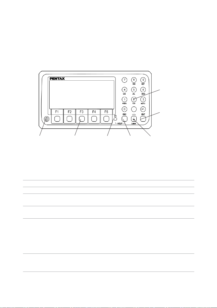
DISPLAY AND KEYBOARD
• Basic display and keyboard of R-300X series are described below, and the
function keys of PowerTopoLite are described at “2.ACCESSING THE POWERTOPOLITE”.
• The description concerning only Reflectorless type,R-315NX/R-325NX/R-335NX/
R-322NX/R-323NX,is put in ( ).
OPERATION KEY
Key Description
[POWER] ON/OFF of power supply
[ESC] Returns to previous screen or cancels an operation.
[ILLUMINATION] Turns the illumination of the LCD display and telescope reticle on
and off.
[ENT] Accepts the selected (highlighted) choice or the displayed screen
value.
[LASER] Displays the laser plummet *1,Electronic vial function,and the
LD point screen when you push the laser plummet/electronic vial
key.(Refer to “2.5 Laser Pointer”, “3.2 Laser plummet”, and
“3.5 Leveling with Electronic vial”of “Instruction M anual”).
*1:Only the product with the laser plumb function
[Alphanumeric] At the numerical value screen,the numerical value and the sign “.”
displayed are input. The English characters printed right under
numeric of each key are input.
[HELP] Pressing [lLLU]+[ESC] causes a help menu to appear in
A MODE or B MODE or causes a help message to appear.
Alphanumeric
and +/- key
Enter key
Power supply key Function key Illumination key ESC key Laser plummet and
Electronic vial key
Page 7

7
FUNCTION KEY
Display F. Key Description
• MODE A
[MEAS] F1 Pressing this key one time measures the distance in
normal mode (another measurement type can be selected
by Initial Setting 2.)
[MEAS] F1 Pressing this key twice measures the distance in coarse
mode (another measurement type can be selected by
Initial Setting 2.)
[TARGET] F2 Select the target type by following order.
SHEET / PRISM / REFRECTORLESS
(Reflectorless type instrument)
SHEET/PRISM
(Prism type instrument)
[0 SET] F3 Resets the horizontal angle to 0°0’ 0”by pressing twice.
[DISP] F4 Switches the display composition in the order
“H.angle / H.dst./ V.dst.”, “H.angle / V.angle / S.dst.”and
“H.angle / V.angle / H.dst./ S.dst./ V.dst.”
[MODE] F5 Switches the screen between MODE A and MODE B.
• MODE B
[S.FUNC] F1 PowerTopoLite Special Functions
[ANG SET] F2 Brings up the angle setting screen for setting angle-related
parameters
(H.ANGLE / %GRADE,H.ANGLE INPUT and R/L REVERSE).
[HOLD] F3 Pressing this key twice retains (holds) the horizontal angle
shown on the display.
[CORR] F4 Brings up the screen for changing the target constant,
temperature.
Pressure setting.
[MODE] F5 Toggles the screen between MODE A and MODE B.
Page 8

8
• Other functions
[] F1 Moves the cursor to the left.
[] F2 Moves the cursor to the right.
[] F1 Goes back five items on the screen.
[] F2 Goes forward five items on the screen.
[] F3 Moves the cursor up.
[] F4 Moves the cursor down.
[RETICLE] F3 Changing the reticle illumination when pressing
illumination key.
[LCD] F4 Changing the LCD contrast when pressing
illumination key.
[ILLU] F5 Changing the LCD illumination when
pressing illumination key.
[CLEAR] F5 Clear the figure.
[SELECT] F5 Open the selection window.
• The Function keys of each PowerTopoLite function are described at
“ACCESSING THE POWERTOPOLITE”and at the each function.
Page 9

9
DISPLAY COMBINATION OF MODE A OR MODE B
Function MODE A MODE B
F1 MEAS S.FUNC
F2 TARGET ANG SET
F3 0 SET HOLD
F4 DISP CORR
F5 MODE MODE
• Mode A or Mode B is switched by pressing [F5] [MODE].
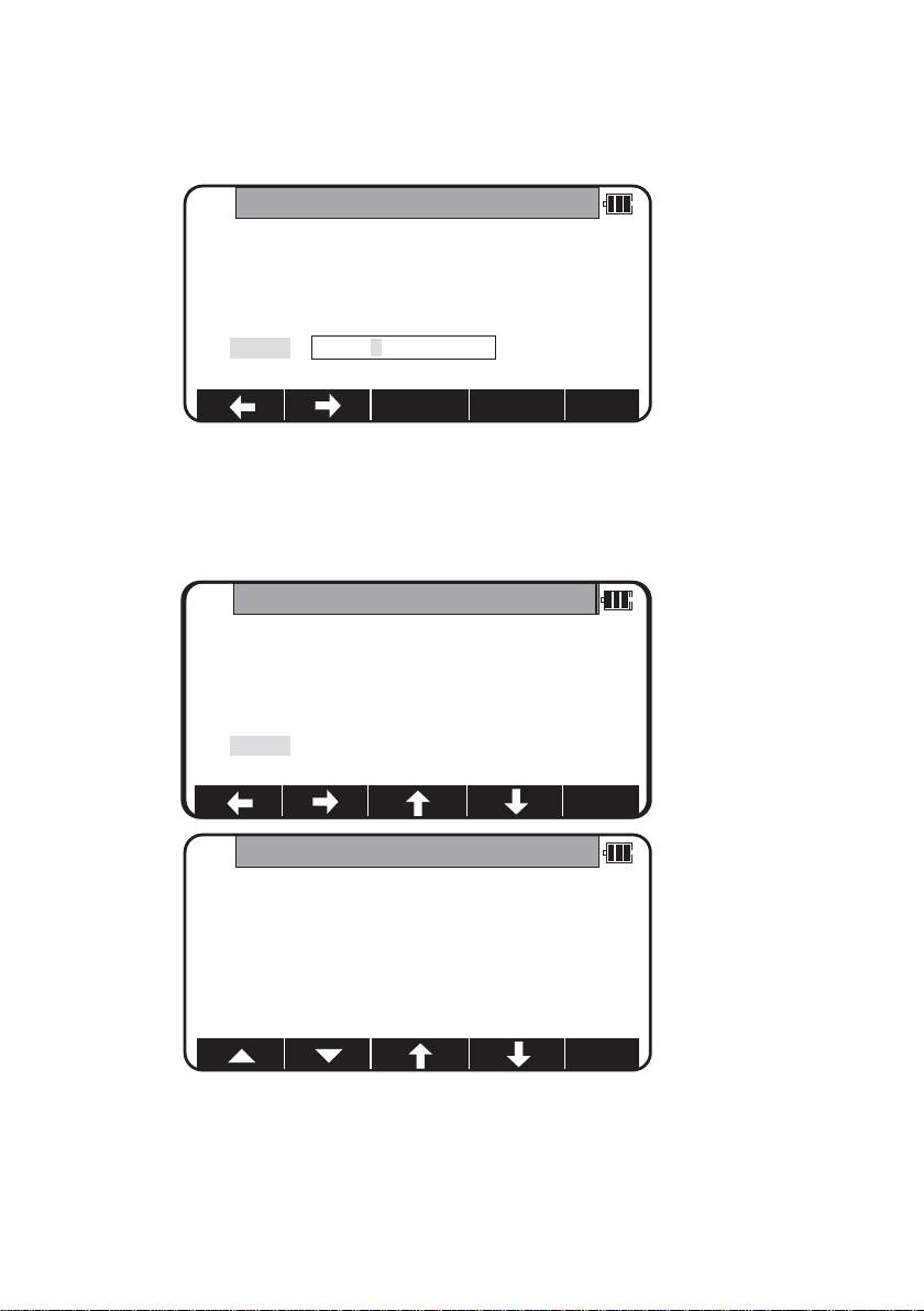
ALPHANUMERIC INPUT
The point name etc.is input by the alphanumeric keys as following.
Key Letter under key Letter & figure order to input
[0] [@][.][_][-][:][/][0]
[1] PQRS [P][Q][R][S][p][q][r][s][1]
[2] TUV [T][U][V][t][u][v][2]
[3] WXYZ [W][X][Y][Z][w][x][y][z][3]
[4] GHI [G][H][I][g][h][i][4]
[5] JKL [J][K][L][j][k][l][5]
[6] MNO [M][N][O][m][n][o][6]
[7] [??][?][!][_][ ][^][|][&][7]
[8] ABC [A][B][C][a][b][c][8]
[9] DEF [D][E][F][d][e][f][9]
[.] [.][,][:][;][#][(][)]
[+/-] [+][-][*][/][%][=][<][>]
Page 10

10
1.INTRODUCTION
1.1 Introduction
Thank you for your first looks at PowerTopoLite by reading this manual.
The PowerTopoLite is a user friendly data collection and calculation program for the
PENTAX total station R-300X series.
PowerTopoLite is developed based on PowerTopo, which is known as versatile on-board
software for PENTAX ATS total station series.The optimum combination of PowerTopo
and R-300X hardware makes PowerTopoLite as an easy and useful fieldwork tool.
The icon based main menu offers you the following possibilities.
• FILE MANAGER
• MEASURE
• VIEW AND EDIT
• FREE STATIONING
• STAKE OUT
• CALCULATIONS
• VPM
• RDM
• TRAVERSE
• TRANSFER
• PREFERENCE
Page 11

11
1.2 Before using the PowerTopoLite manual
• Memories in the instrument
The R-300X series instrument incorporates not only the PowerTopoLite surveying
programs as the Special function but also File manager and Data transfer programs.
The internal memory in the instrument can store the maximum 7500 point’s data.
• Relations between the Memory and each Function
Function Read from the stored data Write to the stored data
Measure SP,BSP SP, BSP,FP (SD)
Stake Out SP, BSP,SOP SP,BSP,SOP, OP
Point to Line SP,BSP, KP1, KP2 SP,BSP, KP1, KP2,OP
Free Stationing Each KP Each KP,SP (CD)
Traverse SP,BSP SP,FP (SD)
VPM SP,BSP, Each KP SP,BSP,Each KP, CP (CD)
Station point: SP Foresight point: FP Backsight point: BSP Stakeout point: SOP
Known point: KP End point: EP Observation point: OP Conversion data: CD
Conversion point: CP Crossing point: CRP Sur veyed data: SD
Page 12

12
• IH and PH
IH stands for “Instrument Height”and PH stands for “Prizm Height”.
• The PowerTopoLite manual mainly describes the R-300X special functions,and the
basic operations are described in the (basic) R-300X manual.And,therefore,refer to
the R-300X basic manual regarding the R-300X general instrument operations.
The PowerTopoLite screens vary with the selections of the “Preference”.
The factory default settings of the Preference are shown there.It is also possible to
select “Process type” that tak es over the functionality of “PowerTopoLite”or “Structure
type”that takes over the functionality of our past product in ”Action Method Selection”.
• The R-300X series instrument has a Job name of “PENTAX”as its default setting.
And,therefore,each data is stored in the “PENTAX”unless another new Job name is
created. When another Job name is created,each data is stored in the new Job name.
• The input range of the X,Y and Z Coordinate is “-99999999.998”- “99999999.998”.
• The input range of the Instrument and Prism height is “-9999.998”- “9999.998”.
• The PC,PointCodeList,is added to the PN,Coordinates X,Y,Z and IH (PH or HI) and
you can input your desired attributes for the point.If you have PointCodeList in the
job named “PointCodeList”, you can easily select one of the PointCode from the list or
edit one of them after pressing [ENT ]. Please,note that Point Code,which is saved in
the other job can not be refered as a list.
• There are two Coordinates types of Rectangular and Polar.The VO,TO offset and the
remote measurement are possible when you select the Rectangular Coordinates.
• When you measure in EDM SETTINGS of COARSE TRACKING,the R-300X displays a
distance value to two decimal places.However,distance data of polar coordinates are
displayed by EDIT function to three decimal places even,and sent to four decimal
place. So, “0“ or “00” is added to the distance data after the third decimal point in
COARSE TRACKING mode.
For example
Displayed value: 123.45
Displayed by EDIT: 123.450
Sent polar data: 123.4500
• Rectangular coordinates is displayed,stored,and sent to three decimal place even if
in COARSE TRACKING or FINE MEASURE mode.
• You can change the distance measurement mode during measuring operation by
pressing the EDM key at the MEASURE and VPM functions.
• The same Point Name of the plural polar points can be saved.
Page 13
13
2.ACCESSING POWERTOPOLITE
2.1 How to access PowerTopoLite
To access the R-300X Special Functions of the PowerTopoLite,perform the following
procedures.
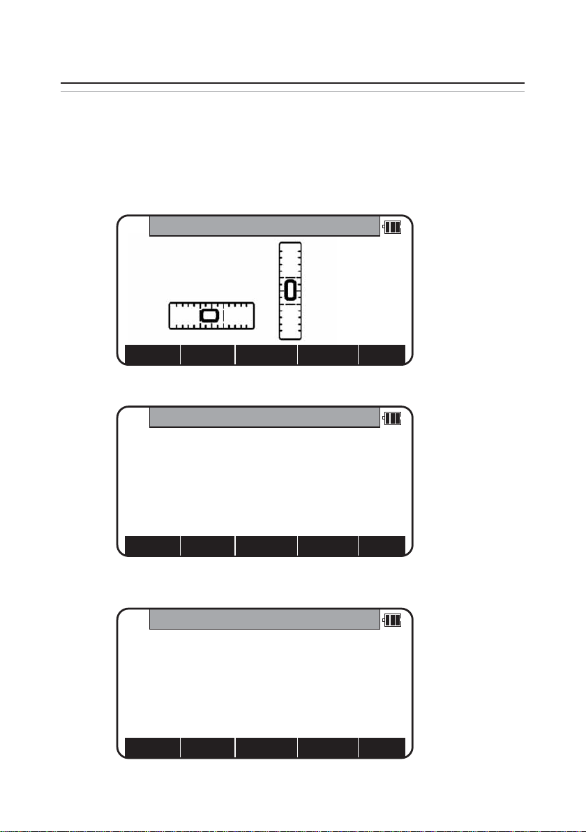
a.Press the Power (ON/OFF) key to view the R-300X start-up screen.
b.It turns to ELECTRONIC VIAL screen after a while.
c. Press the [ESC],[Laser] or [ENT] to view Mode A screen.
d.Press the [F5][MODE] to view Mode B screen.
T.COMP.
ON
30”/1DIV
MODEB
H.angle
123° 45’ 25”
H.dst
V.dst
HOLDANGSETS. FUNC CORR
MODE
MODEA
H.angle
123° 45’ 25”
H.dst
V.dst
0 SETTARGETMEAS DISP
MODE
ELECTRONIC VIAL
PLUMADLD POINT
SENS.
Page 14
14
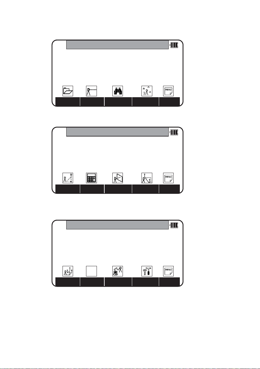
e.Press [F1][S.FUNC] to view Functions of PowerTopoLite screen.
f.Press [F5][PAGE] to view another Function combination of PowerTopoLite screen.
g.Press [F1][S.FUNC] to view Functions of PowerTopoLite screen.
PowerTopoLite
I/OTRAV PREF
PAGE
PowerTopoLite
VPMCALCSTAK RDM
PAGE
PowerTopoLite
VIEWMEASFILE FREE
PAGE
Page 15
15
2.2 Allocation of each PowerTopoLite Function key
a.FILE,MEAS,VIE W,FREE,STAK,CALC, I/O and PREF functions
KEY Function Description
F1 FILE File Manager
F2 MEAS Measure
F3 VIEW View and Edit
F4 FREE Free stationing
Other four Functions are viewed by pressing [F5][PAGE].
KEY Function Description
F1 STAK Stake out
F2 CALC Calculation
F3 VPM Virtual Plane Measurement
F4 RDM Remote Distance Measurement
Other four Functions are viewed by pressing [F5][PAGE].
KEY Function Description
F1 TRAV Stake out
F2 N/A
F3 I/O Input and Output
F4 PREF Preference
b. INVERSE,POINT COORDINATES,LINE-LINE INTERSECTION functions
CALCULATION screen is viewed by pressing [F2][CALC]. The CALCULATION consists of
COGO,2D SURFACE and 3D SURFACE & VOLUME functions.
COGO screen is viewed by selecting 1.COGO and pressing the [ENT].
CALCULATION
1.COGO
2.2D SURFACE
3.3D SURFACE & VOLUME
4.REM
Page 16
16
The COGO consists of INVERSE,POINT COORDINATE, CIRCLE RADIUS LINE-ARC
INTERSECTION,LINE-LINE INTERSECTION, ARC-ARC INTERSECTION,DISTANCE OFFSET,
POINT DISTANCE OFFSET,POINT DISTANCE OFFSET,ARC DISTANCE OFFSET,
and functions.
COGO
1.INVERSE
2.POINT COORDINATE
3.CIRCLE RADIUS
4.LINE-ARC INTERSECTION
5.LINE-LINE INTERSECTION
COGO
5.LINE-LINE INTERSECTION
6.ARC-ARC INTERSECTION
7.DISTANCE OFFSET
8.POINT DISTANCE OFFSET
9.ARC DISTANCE OFFSET
Page 17

17
2.3 Typical Function keys of PowerTopoLite
Following function keys are typical ones of PowerTopoLite and each function key is
described for each function of this Manual.
KEY Description
ENTER Opens the input screen of Coordinate values etc.
PAGE Views another function combination.
SELECT Selects the Character and moves to next input at PN
input etc.
ACCEPT Enters the displayed values without new Coordinates
value input etc.
INPUT Inputs your desired Horizontal angle.
BSP Views the BSP SETUP screen to input its Coordinates.
SAVE Saves inputted data.
ME/SAVE Measures and then saves inputted data.
EDIT Changes the Point name or Prism height.
REMOTE Views your aiming point Coordinates.
OFFSET Views the Target Coordinates adding the offset values.
STATION Returns to the STATION POINT SETUP screen.
H.ANGLE Returns to the STATION POINT H.ANGLE SETUP screen.
LIST Views the POINT SELECTION FROM THE LIST screen.
ZOOM ALL Returns to original size.
ZOOM IN Magnifies the graphics size.
ZOOM OUT Reduces the graphics size.
DISP Views point or point & graphic or point & point name
or all.
DELETE Views the POINT DELETION screen.
FIND PN Views the PN search screen by inputting the Point name.
ADD Allow you to add more points for the free stationing.
CALC Starts the calculation of the free stationing.
NEXT Views the next k nown point Coordinates setup screen.
DATA Views the TARGET POINT screen.
TARGET Selects the Target type.
EDM Selects the EDM settings.
ALL Selects all points of current job.
ORDER The order of selected points.
Page 18
18
3.FILE MANAGER
The Data storage memory status,creating a new Job name and the Selection
and Deletion of a Job name are executed by this function.
From the PowerTopoLite screen,press [F1][FILE] to view the FILE MANAGEMENT screen.
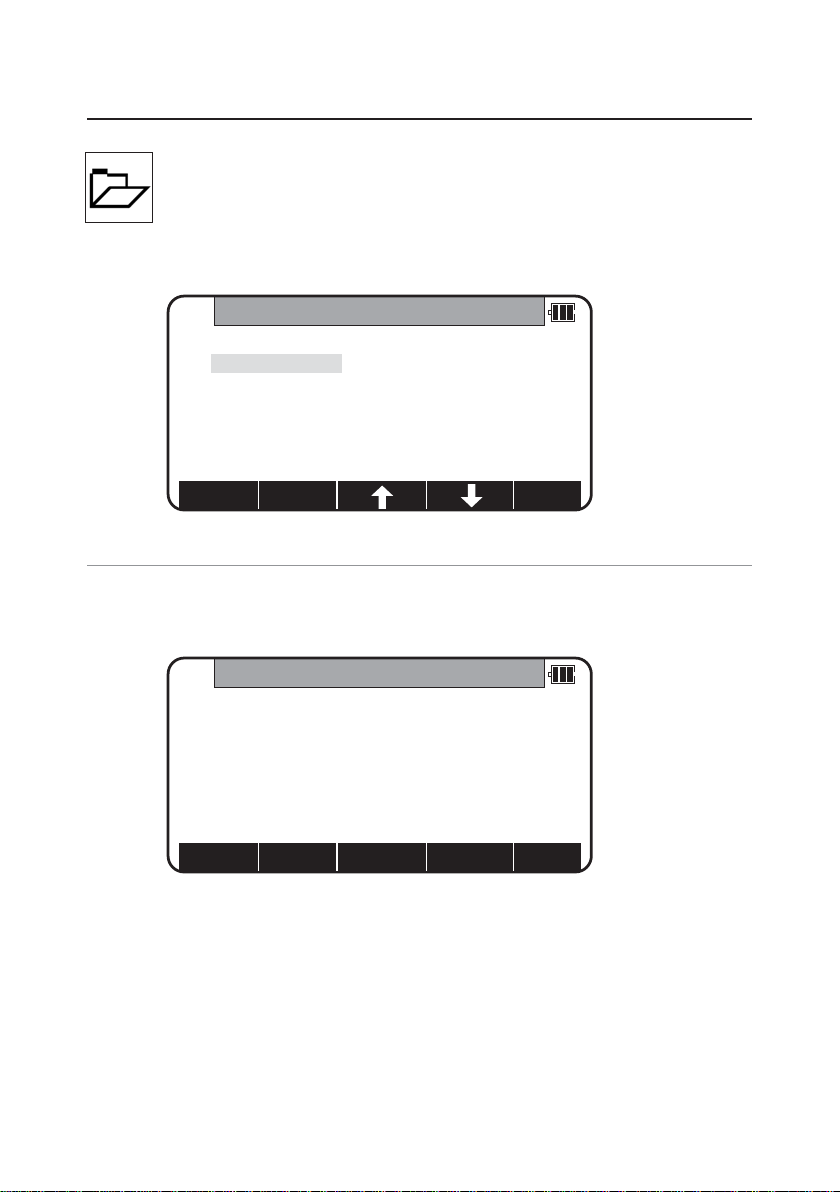
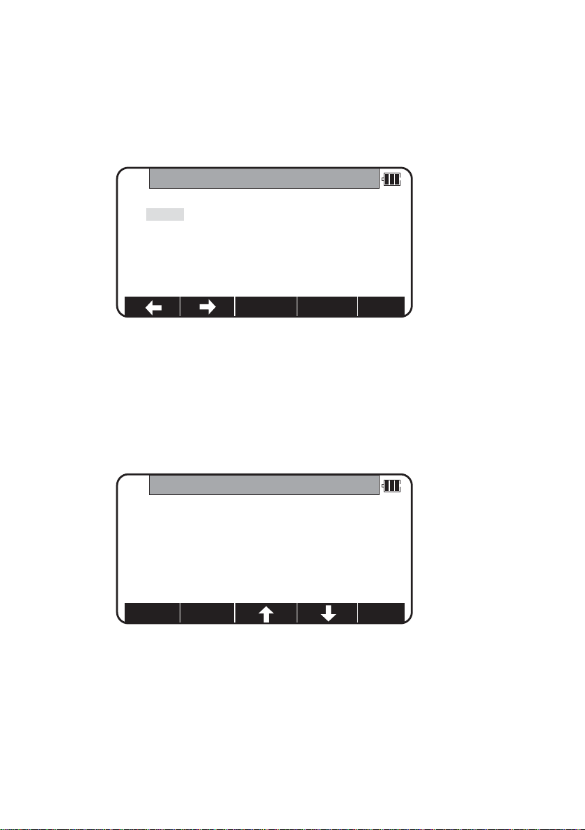
3.1 Information of the remaining memory available
Press [ENT] to view INFORMATION screen.
The remaining memory available and a JOB name PENTAX are viewed on the screen.
The Job name “PENTAX”is a default setting.
The product shown as follows does not display Date.
R-315EX,R-325EX, R-335EX,R-326EX.
FILEMANAGEMENT
1.INFORMATION
2.CREATE
3.SELECT
4.DELETE
5.ALL CLEAR
INFORMATION
Memory free:93 %
Current job:PENTAX
1004 Point saved
The renewal date:2005/04/22 20:07:38
Page 19
19
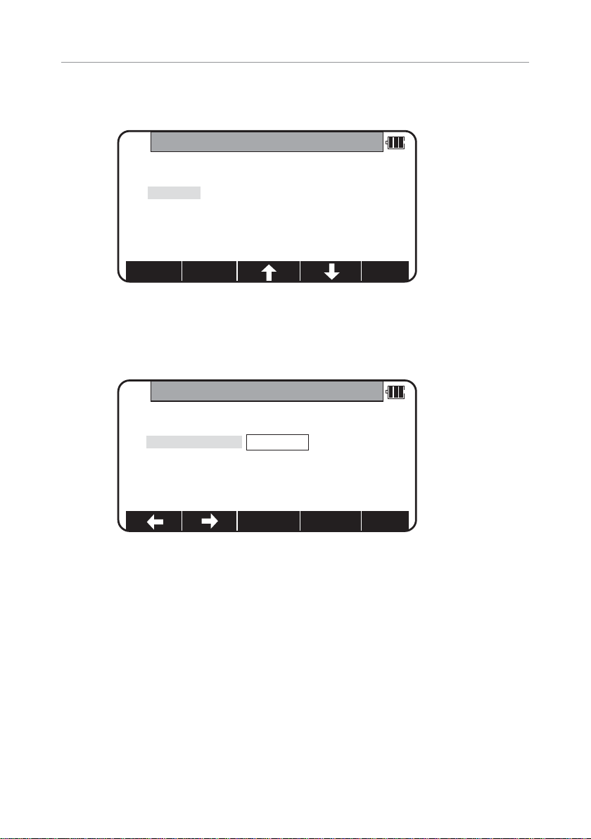
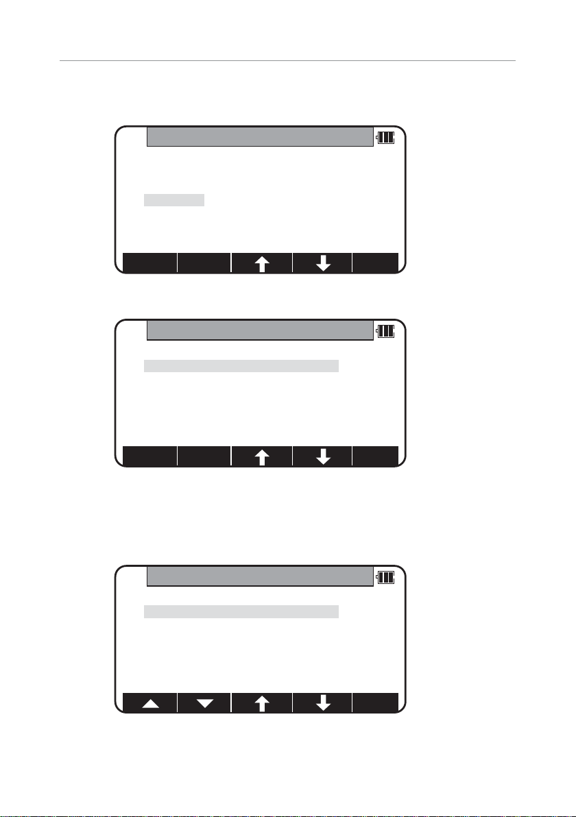
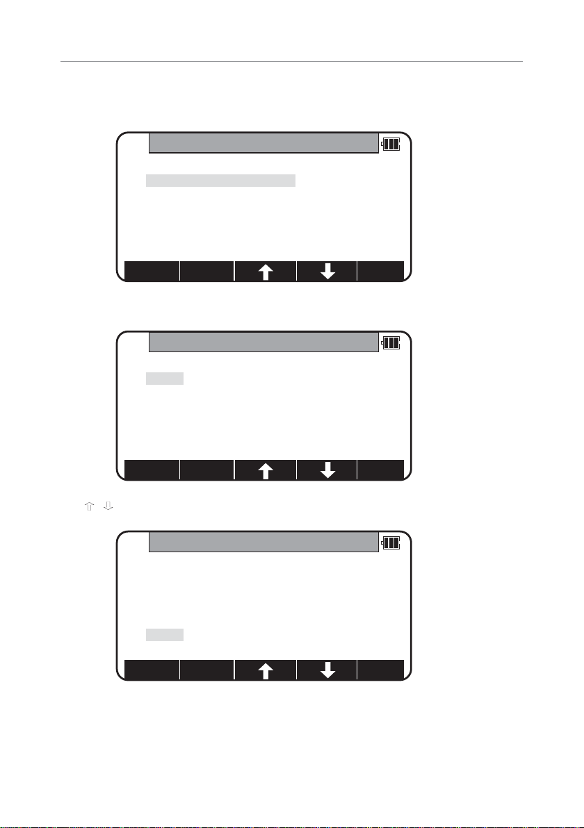
3.2 Creation of a new Job
Select 2.CREATE by down arrow key.
Press [ENT] to view the JOB NAME INPUT screen.
• The Job name input method can be selected by the “Input method selection”
of the “Preference”. This is the “10 KEY SYSTEM”input selec tion.
• If a new Job is created,the new data are stored in this new Job.
PENTAX
FILEMANAGEMENT
1.INFORMATION
2.CREATE
3.SELECT
4.DELETE
5.ALL CLEAR
FILEMANAGEMENT
1.INFORMATION
2.CREATE
3.SELECT
4.DELETE
5.ALL CLEAR
BS CLEAR
TO 123
Page 20
20
3.3 Selection of a Job name
Select 3.SELECT by pressing the down arrow key.
Press [ENT] to view JOB SELECTION screen.
3.3.1 Selection of a Job
Select 1.JOB LIST SEARCH and press [ENT] to view its screen.
JOB LIST is a list of all stored Jobs.
Select your desired Job name and press [ENT ] to select.
FILEMANAGEMENT
1.INFORMATION
2.CREATE
3.SELECT
4.DELETE
5.ALL CLEAR
JOB SELECTION
1.JOB LIST SEARCH
2.JOB NAME SEARCH
JOB LISTSEARCH
1.PENTAX 2004/12/24
2.NERIMA 2005/01/01
3.TOKYO 2005/02/15
Page 21
21
MEAS TARGET 0 SET DISP MODE
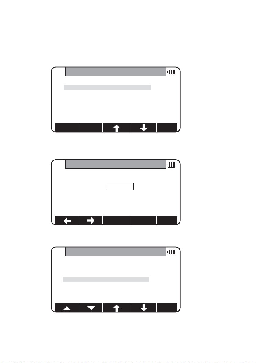
3.3.2 Selection by a Job name input
Select 2.JOB NAME SEARCH by pressing the down arrow key.
• The JOB NAME SEARCH is the search by inputting your desired job name.
Press [ENT] to view the JOB NAME INPUT screen.
Input your desired JOB NAME and press [ENT] to view the JOB LIST SEARCH screen.
Press [ENT] to select this.
JOB SELECTION
1.JOB LIST SEARCH
2.JOB NAME SEARCH
TOKYO
JOBNAMEINPUT
BS CLEAR
TO 123
JOB LISTSEARCH
1.PENTAX 2004/12/24
2.NERIMA 2005/01/01
3.TOKYO 2005/02/15
Page 22
22
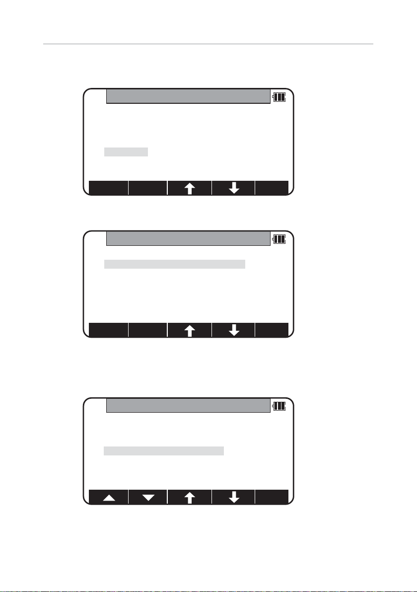
3.4 Deletion of a Job name
Select 4.DELETE by pressing the down arrow key.
Press [ENT] to view JOB DELETION screen.
3.4.1 Deletion from a Job list
Select 1.JOB LIST SEARCH and Press [ENT] to view its screen.
FILEMANAGEMENT
1.INFORMATION
2.CREATE
3.SELECT
4.DELETE
5.ALL CLEAR
JOB DELETION
1.JOB LIST SEARCH
2.JOB NAME SEARCH
JOB LISTSEARCH
1.PENTAX 2004/12/24
2.NERIMA 2005/01/01
3.TOKYO 2005/02/15
Page 23
23
If TOKYO is selec ted,deletion confirmation screen is viewed.
Press [ENT] to delete or [ESC] to abort.
3.4.2 Deletion from a Job name search
Select 2.JOB NAME SEARCH by pressing the down arrow key.
Press [ENT] to view the JOB NAME INPUT screen.
DELETEJOBCONFIRMATION
TOKYO
will be deleted.OK ?
Press [ENT] to confirm
Press [ESC] to abort.
JOB DELETION
1.JOB LIST SEARCH
2.JOB NAME SEARCH
JOBNAMEINPUT
BS CLEAR
TO 123
TOKYO
1.JOB LIST SEARCH
2.JOB NAME SEARCH
Page 24

24
Input your desired JOB NAME to delete and press [ENT] to view the
DELETE JOB CONFIRMATION screen.
Press [ENT] to delete or [ESC] to abort.
The R-300X series instrument has a Job name of the “PENTAX”as its default setting.
Therefore,each data is stored in “PENTAX”unless another new Job name is
created. When another Job name is created,each data is stored in the new Job name.
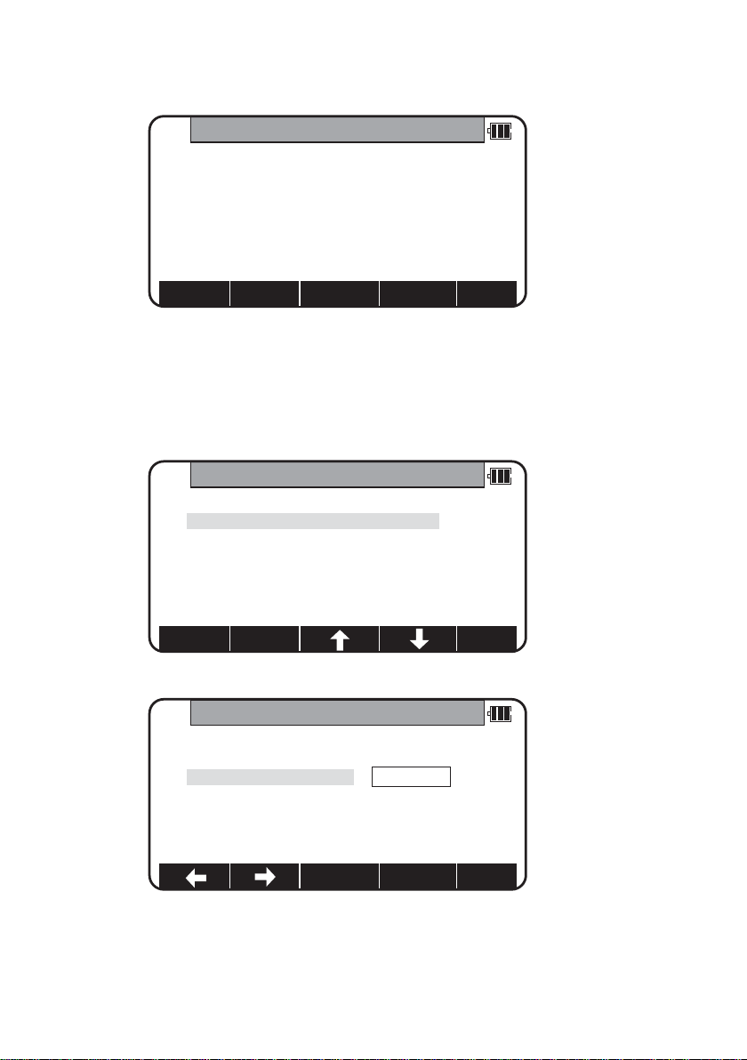
3.5 All Clear
Select 5.All Clear by pressing the down arrow key.Press [ENT ] to view its screen.
Warning:
When [CLEAR] is pushed,all JobFile is deleted.
Note: Creating several new JOB files and writing in or rewriting data on the same
JOB files repeatedly may cause time of writing-in and rewriting the data to be
slower. Also af ter saving the date until the memory capacity becomes almost
full,then deleting some JOB files in order to secure open memory capacity,
it may cause time of writing-in and rewriting the data to be slower.
In case the time of writing-in or rewriting the data become slower,
send the necessary data to PC for backup,then enter ‘All Clear’in FILEMANAGER.
The above procedure will format the inside memory automatically and improve the time
or writing-in and rewriting the data.Be sure in this case all the JOB files will be deleted.
DELETEJOBCONFIRMATION
TOKYO
will be deleted.OK ?
Press [ENT] to confirm
Press [ESC] to abort.
ALLCLEAR
Attention!!
All rect.data and
the polar data are deleted.
Page 25
25
4.MEASURE
An operator can measure the Foresight point Coordinates from the “Station point
Coordinates and Backsight Coordinates”or the “Station point Coordinates and Azimuth”,
and can store the Point name and measured Coordinates in the memory.When the
Coordinates of the Station point and Backsight point are already stored in the memory,the
new Coordinates input can be omitted by calling or searching from the point name LIST.
The point name is within 15 characters and the Coordinates are within 8 in integer and
3 in decimal number.There are two Coordinates types of Rectangular and Polar
Coordinates in this [MEASURE].
The Offset at the Target point is possible and the Remote measurement by aiming at any
point is possible as well when you select the Rectangular Coordinates.
An operator can perform the [MEASURE] function only when the Telescope is at the
“Face left position”.
Select the Target type before performing the [MEASURE].
After measuring rectangular coordinates by [MEASURE] function of PowerTopoLite,
it is possible to display Angle and Distance by switching the [F3] key.
When Remote mode is selected,Angle and Distance are also calculated according to
the coordinates of the aiming point on real time.
When Offset mode is selected,Angle and Distance are also calculated according to the
coordinates where offset value is added.
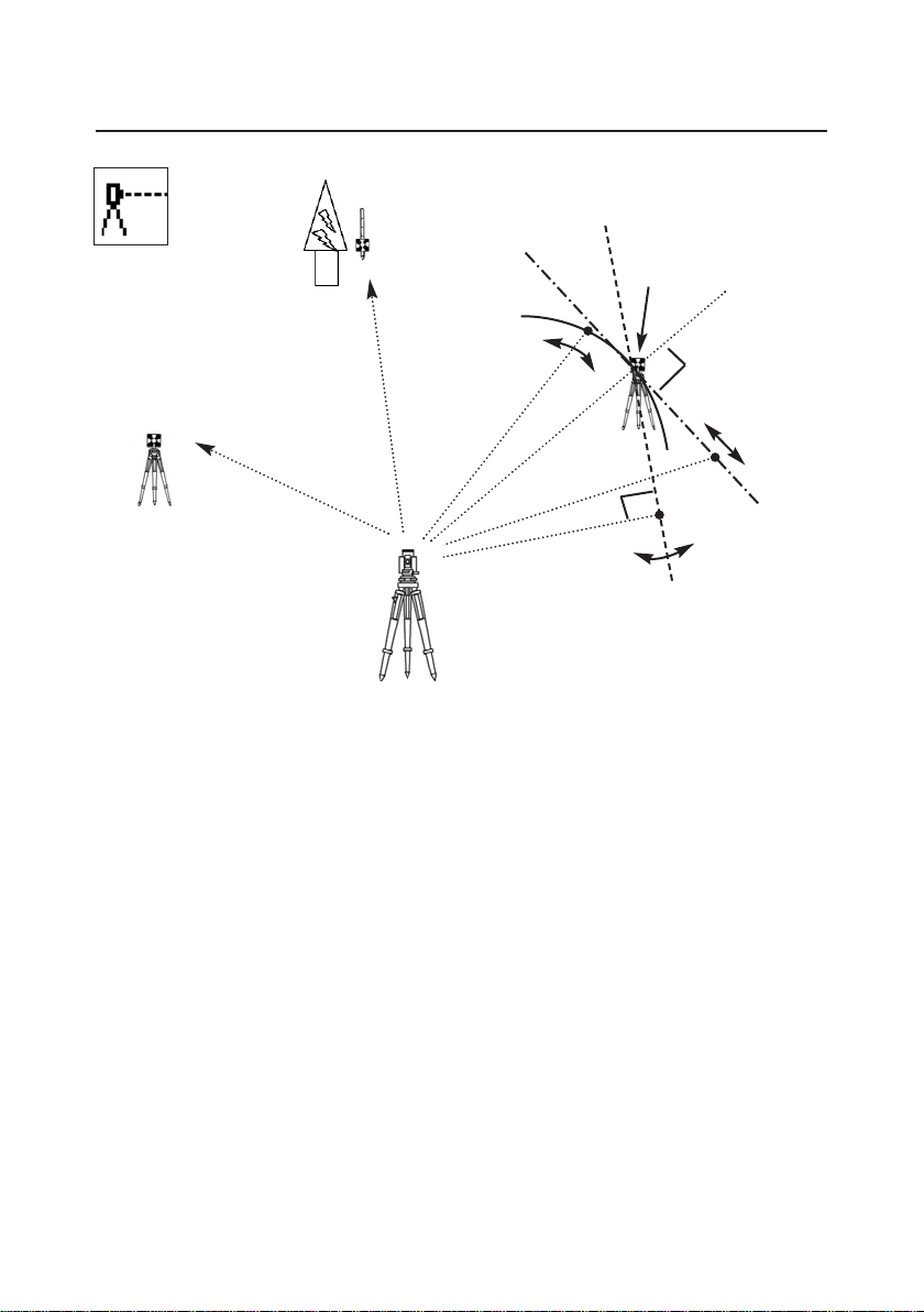
Offset
1.Cylinder
3.Rotated
Reference P.
Remote
2.Fixed plane
Azimuth
Backsight P.
Coordinates
Station point
Page 26
26
4.1.1 Point name,PN,input
Press [ENT] to view the PN screen.
The [ENT] is used for both accepting the selected choice and opening the input screen
of the Coordinates values etc.
Input your desired point name by pressing keys,and after all Characters are input,
press [ENT].
Four character selection methods are available.(Refer to the “13.3 Input method selection”)
4.1.2 Coordinates,X,Y, Z,IH,and PC input
It goes 2.X coordinate automatically.
PN
BS CLEAR
TO 123
1. PN:
2. X: + 00000000.000m
3. Y: + 00000000.000m
4. Z: + 00000000.000m
5. IH: 0000.000m
X
1.PN: POT1
2.X: + 00000000.000m
3.Y: + 00000000.000m
4.Z: + 00000000.000m
5.IH: 0010.000m
SAVE LIST
ACCEPT
Page 27
27
4.1 Station setup [By Rectangular Coordinates]
Press [F2][MEAS] of the PowerTopoLite screen to view the MEASURE METHOD SELECTION
screen.
Select 1.RECTANGULAR COORD. and press [ENT] to view the STATION POINT SETUP
screen.
The
/ mark is used to scroll up / down. 6.PC is viewed by scrolling down.
MEASURE METHODSELECTION
1. RECTANGULAR COORD.
2. POLAR COORD.
STATION POINTSETUP
1. PN:
2. X: + 00000000.000m
3. Y: + 00000000.000m
4. Z: + 00000000.000m
5. IH: 0000.000m
SAVE
LIST
ACCEPT
STATION POINTSETUP
2. X: + 00000000.000m
3. Y: + 00000000.000m
4. Z: + 00000000.000m
5. IH: 0000.000m
6. PC:
SAVE
LIST
ACCEPT
Page 28
28
Press [ENT] to view the X coordinate input screen.
Input X,Y and Z coordinates,Instrument height and PC as follows.
Input your desired X coordinate value by pressing each keys.
Y coordinate:
Press [ENT] to view the Y coordinate input screen.Input your desired Y coordinate value
by pressing keys.
Z coordinate:
Press [ENT] to view the Z coordinate input screen.Input your desired Z coordinate value
by pressing each keys.
X
1.PN: POT 1
2.X: + 00000000.000m
3.Y: + 00000000.000m
4.Z: + 00000000.000m
5.IH: 0000.000m
CLEAR
Y
1.PN: POT 1
2.X: + 00000000.000m
3.Y: + 00000002.000m
4.Z: + 00000000.000m
5.IH: 0000.000m
CLEAR
Z
1.PN: POT 1
2.X: + 00000000.000m
3.Y: + 00000000.000m
4.Z: + 00000000.000m
5.IH: 0000.000m
CLEAR
Page 29
29
IH value:
Press [ENT] to view the IH, Instrument height,screen.Input your desired IH value by
pressing each keys.
PC,Point Code:
Press [ENT] to view and input the PC, Point code,screen.
If PointCode exists,you can easily select them from the list.Then after pressing [ENT ],
you can edit Point Code data.For using Point Code List, please refer to “4.4.Point Code”.
IH
1.PN:POT 1
2.X: + 00000000.000m
3.Y: + 00000000.000m
4.Z: + 00000000.000m
5.IH: +0001.500m
CLEAR
PC
2.X: + 00000100.000m
3.Y: + 00000200.000m
4.Z: + 00000010.000m
5.IH: 0010.000m
6.PC:
CLEAR
POINT CODELIST
1. ABC
2. DEF
3. GHI
4. JKL
5. MNO
Page 30

30
After pressing [ENT], you can edit Point Code data.
Input your desired PC name by pressing keys,and press [ENT ] to view nex t screen.
If “PROCESS TYPE”is selected in “Action method selection”,after input/confirm PC data
the inputted POT1 data will automatically be stored in the memory.Then the panel
“STATION POINT H.ANGLE SETUP” will be displayed.
But,if “STRUCTURE TYPE”is selected in “Action method selection”,it is necessar y to press
[ACCEPT] to proceed next panel.
PC
2.X: + 00000100.000m
3.Y: + 00000200.000m
4.Z: + 00000010.000m
5.IH 0010.000m
6.PC: TEST POI
BS CLEAR TO 123
Page 31

31
• [LIST] k ey
All stored points can be displayed,deleted and searched as follows
by pressing [F2][LIST].
Press the [F2][LIST] to view POINT SELECTION FROM THE LIST screen.
Press [F1][DELETE]
to view POINT DELETION screen.
Press [F2][FIND PN]
to view PN screen.
POINTSELECTION FROM THE LIST
1 / 15
PNx POT1
Xx + 00000100.000m
Yx - 00000200.000m
Zx + 00000010.000m
DELETE FINDPN
POINTDELETION
POT1
Do you really want to delete it ?
Press [ENT] to confirm.
Press [ESC] to abort.
PN
1.PN*
2. X: + 00000000.000 m
3. Y: + 00000000.000 m
4. Z: + 00000000.000 m
BS CLEAR TO 123
POINTSELECTIONFROM THELIST
2 / 15
PNx POT2
X x + 00000300.000 m
Y x - 00000600.000 m
Z x + 00000010.000 m
DELETE
FINDPN
[ENT ] to view POINT SELECTION
FROM the LIST screen.
Page 32

32
Press [ENT] to view STATION POINT
SETUP screen.
STATION POINT SETUP
1.PN: POT2
2.X: + 00000300.000 m
3.Y: - 00000600.000 m
4.Z: + 00000010.000 m
5.IH: 0001.200 m
SAVE
LIST ACCEPT
4.2 Station Orientation
Press the [F1][ACCEPT] to view the STATION POINT H.ANGLE SETUP screen.
Please,note that the rotation of the “H.angle”depends on the rotation setting of
“Coordinate axis definition”.
STATIONPOINT H. ANGLE SETUP
H.angle XXX°XX’XX”
INPUT 0 SET HOLD BSP
Page 33

33
4.2.1 Station orientation
Input the H.angle by pressing [F2][INPUT],[F3][0SET] and [F4] [HOLD] or
Reference point Coordinates by pressing [F5][BSP].
Pressing [F2][INPUT] Pressing [F5][BSP]
Press [ENT] to view the input window.
Press [ENT] after entering the Horizontal angle.The AIM AT THE REFERENCE
POINT screen is viewed when “1.ON”of “7.REQUEST AIMING”of “Preference”is selected
and not viewed when “2.OFF”is selec ted.
In case of that BSP Coordinates are inputted,this message is always viewed on the screen.
Coordinates display and Angle & Distance display.
Press the [ENT] at the STATION POINT H.ANGLE SETUP screen to view the MEASURE screen.
H.ANGLE
H.angle XXX°XX’XX”
BSPSETUP
1.PN:
2.X: + 00000100.000m
3.Y: + 00000310.000m
4.Z: + 00000110.000m
5.PC
SAVE LIST ACCEPT
CLEAR
AIM AT THE REFERENCE POINT.
Aim at the reference point.
Press [ENT] when ready.
ESC ENT
STATION POINTSETUP
H.angle XXX°XX’XX”
MEASURE
PN
PH X.XXX m
X
Y
Z
MEAS SAVE PAGEEDITME/SAVE
BPSHOLD0 SETINPUT
Page 34

34
Press the [MEAS] to measure the Distance and display the Coordinates.
1) Press [F5][PAGE] twice to view [F3][ANG & DIST].
2) Press [F3][ANG & DIST] to view [F3][COORD.] and Angle and Distance values.
3) Press [F3][COORD.] to view [F3][ANG&DIST] and Coordinates.
Stakeout can be selected by pressing [F4][STAKEOUT ].
4.3 Measuring
Aim at the reference point and press [ENT] to view the MEASURE screen.
Then,aim at the Target point and press the [F1][MEAS] to measure it.
Press [F3][ME/SAVE] to measure and save the measured data.
Press [F2][SAVE] to save the measured data.
Press [F4][EDIT] to edit the PN,Point Name,PH,Prism Height and PC, Point Code.
Input your desired Point name,Prism height and Point code.
Press [F5][ACCEPT] if the current PN,PH and PC are acceptable.
If PointCode exists,you can easily select them from the list or edit one of them after
pressing the [ENT]. For using Point Code List,please refer to “4.4. Point Code”.
MEASURE
PN
PH X.XXX m
X + X.XXX m
Y + X.XXX m
Z + X.XXX m
ANG.& DIST.
PN
PH X.XXX m
H.angle XXX° XX’XX”
V.angle YY° YY’YY”
H.dst X.XXX m
DISPCOORD
PAGESTAKEOUTANG&DISTTARGETEDM
MEASURE
PN POT3
PH 1.200 m
X + 373.205
Y - 73.205
Z + 71.149
PAGEEDITME/SAVESAVEMEAS
Page 35

35
4.4 Point Code
The PC,PointCodeList can be used for adding your desired attributes to Rect.and
Polar data.If point codes are stored under the job named "PointCodeList",you can easily
select one of the PointCode from the list or edit one of them after pressing [ENT].
Please,note that Point Code,which is saved in the other job can not be refered as a list.
“PointCodeList”can be created by either using “5.2 Create the Rectangular Point”
function or Importing “PointCodeList”file.
Making “PointCodeList”:
Create / select “PointCodeList”job using “3.FILE MANAGER”. Then input point data
according to “5.2 Create the Rectangular Point”. Input any value into “PN”field and leave
the X,Y, and Z field “0”.And input PointCode data into “PC”field.
Importing “PointCodeList”file:
PointCodeList can be used after importing it from external devices (ex.PC).
After importing,it is stored in the internal memory of the instrument.To store user
defined ”PointCodeList”,please carry out following procedure.
Preparing “PointCodeList”file:
Make a “PointCodeList.csv”file with reference to a sample “PointCodeList.csv”file that
is contained in the “R-300X Supplement Disk ”for the format.
Please,note that the newly entered PointCode on the instrument is not added to the
PointCodeList that is stored in the memory.In this case,edit “PointCodeList.csv”separately.
Contents of “PointCodeList.csv”:
1,,PointCodeList,
31,,1,ABC,,,,
31,,2,DEF,,,,
31,,3,GHI,,,,
31,,4,JKL,,,,
31,,5,MNO,,,,
31,,6,PQR,,,,
31,,7,STU,,,,
31,,8,VW,,,,
31,,9,XYZ,,,,
MEASURE
1.PN: POT5
2.PH: 000.000 m
3.PC: XXXX
ACCEPT
Page 36

36
Format of the “PointCodeList”file
Field 1 Field 2 Field 3 Field 4 Field 5 Field 6 Field 7
Description Record Type No. Name Description
Ex.Line 1 1, , PointCodeList, ,
Job record Job No.: Job Name
(N/A) (Fixed for
“PointCodeList”.)
Ex.Line 2 31, , 2, DEF, , , ,
Coord.data Point No.: Point Name Point Code
record (N/A) (Shoul not (Max.15 Character.)
duplicated and
Max.15
Character.)
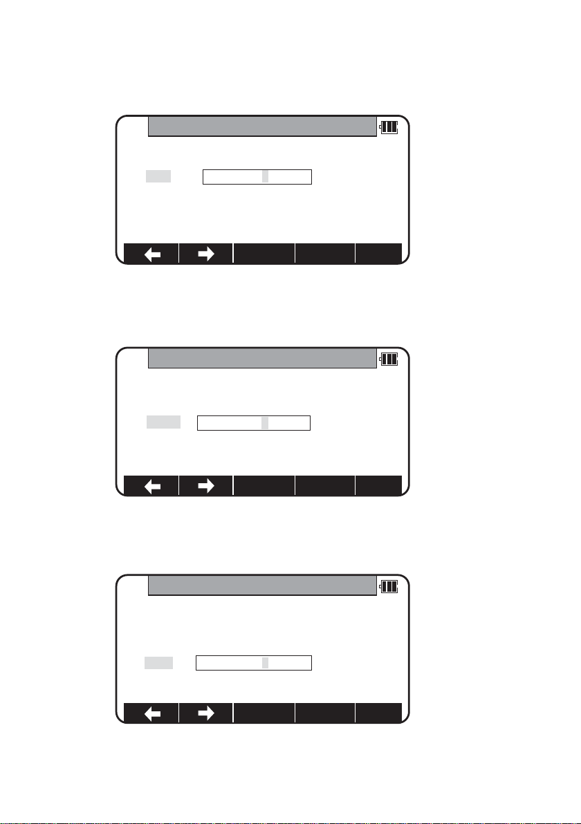
Setting the PROTOCOL:
Press the [F3][I/O] of the PowerTopoLite screen to view the TRANSFER screen.
To check the communication setting, select the “4.COMMUNICATION SETUP”in the
“TRANSFER”screen and press [ENT] to view “COMM.SETTING SELECTION”screen.
Then select “1. RECEIVE RECT.DATA”
and set
“1.BAUD RATE”to “1200”,
“6.X ON/XOFF”to “OFF”for using
“DL-01”, “ON”for using “HYPER
TERMINAL”.
“7.PRO TOCOL ”to “OFF”
“8.RECORD DELIMITER ”to “CR+LF”
and press [ACCEPT].
( cf.“12.3.1 Receiving data setting”)
TRANSFER
1.RECEIVE RECT.DATA
2.SEND RECT.DATA
3.SEND POLASR DATA
4.COMMUNICATION SETUP
Page 37

37
Receive rect.Data:
After setting the parameters,select the “1.RECEIVE RECT. DATA”in the “TRANSFER”screen
and press [ENT] to view “FORMAT SELECTION”screen.In this screen select “3.ExtCSV”to
send PointCodeList.( cf. ”1 Input from the PC ”)
The maximum point which can be received at a time is 1000 points.
After complete data transfer, number of received points is displayed.Press [ENT].
If the name of job in the PointCodeList file (ex.“1.PointCodeList ”) is same as current job
and you want to overwrite or append,select “1. OVER WRITE”or ” 2. APPEND”.
If the name of job in the PointCodeList file (ex.“1.PointCodeList ”) is different
from current job or if you don’t want overwrite or append when jobs names are same,
select “3.SAVE”.
Received data will be written into the internal memory of the instrument.
FORMAT SELECTION
1.DC1
2.CSV
3.EXTCSV
RECEIVING COMPLETED
XXPOINT RECEIVED!
RECEIVED DATA SAVING METHOD
1.OVERWRITE
2.APPEND
3.SAVE
Page 38

38
4.5 Remote,Offset,Station,and H.angle function
4.5.1 Remote
Press [F5][PAGE] to view another MEASURE menu.
Press [F1][REMOTE] once and then quickly press this key again to measure your desired
point Coordinates by moving the telescope.
The displayed Coordinates automatically change according to your aiming point.
The Remote is a function of,so to speak,“Real-time offset ”.If a reference point or offset
point is measured,the Coordinates of your aiming point are calculated based on the
reference plane.
There are three calculation methods of Cylindrical face,Fixed plane and Rotated plane.
They are selected by the “Preference”.Refer to “Remote method selection”.
The calculations are performed on the virtual planes.
To quit the Remote measurement,press [F1][REMOTE] twice again.
MEASURE
PN POT3
PH X.XXX m
X
Y
Z
MEASURE
PN POT3
PH X.XXX m
X
Y
Z
REMOTE OFFSET PAGEH.ANGLSTATION
PAGEEDITME/SAVESAVEMEAS
REMOTE
1.CYLINDER
3.ROTATED
REFERENCE P.
2.FIXED
STATION POINT
Page 39

39
Three type menus can be used by pressing [F5][PAGE]. Another is following menu.
The target type can be selected by pressing [F2][TARGET].
EDM settings can be selected by pressing [F1][EDM].
For example,change 1.PRIM.MEAS KEY (MEAS) to TRACK SHOT or TRACK CONT if
you want to use tracking measurement with primary MEAS key (MEAS).
Coordinates display and Angle & Distance display
1) Press [F5][PAGE] twice to view [F3][ANG & DIST].
2) Press [F3][ANG & DIST] to view [F3][COORD.] and Angle and Distance values.
3) Press [F3][COORD.] to view [F3][ANG&DIST ] and Coordinates.
MEASURE
PN POT3
PH X.XXX m
X
Y
Z
PAGESTAKEOUTANG&DISTTARGETEDM
EDMSETTINGS
1.PRIM.MEAS KEY: MEAS.SHOT
2.SEC.MEAS KEY: TRACK CONT
3.TRACK MIN DISP.: COARSE
4.SHOT COUNT: 1 TIME
5.SHOT INPUT: 01 TIMES
ACCEPT
MEASURE
PN
PH X.XXX m
X + X.XXX m
Y + X.XXX m
Z + X.XXX m
MEASURE
PN
PH X.XXX m
H.angle XXX° XX’XX”
V.angle YY° YY’YY”
H.dst X.XXX m
DISPCOORD
PAGEST AKEOUTANG&DISTTARGETEDM
Page 40

40
OFFSETS
1.RO: 0000.000 m
2.VO: 0000.000 m
3.DO: 0000.000 m
4.TO: 0000.000 m
ACCEPT
RO
1.RO: +0000.000 m
2.VO: +0000.000 m
3.DO: +0000.000 m
4.TO: +0000.000 m
CLEAR
4.5.2 Offset
Press the [F2][OFFSET] to view the OFFSETS screen.
Offset enables you to work with Offsets.The following offsets are available.
Press [ENT] to view the offset input window.Input the RO offset value by pressing keys.
VO,DO and TO values are inputted in the same manner.
After input “TO”value,press [ENT ] to view the MEASURE screen.
(Or press [ESC] then press [ACCEPT].) The offset values are added to X,Y and Z values.
The input value of offset is cleared when you save the surveying point and step forward
to the next surveying point.
OFFSET
PN POT3
PH m
X + offset……
Y + offset……
Z + offset……
PAGEH.ANGLESTATIONOFFSETREMOTE
Page 41

41
RO:Radial O ffset
(RO:On the horizontal plane.Offset P:Along the line of measurement,thus along the slope)
Offset P:O ffset Point
VO:Vertical Offset (Along the third axis)
DO:Distance Offset (Along the line of measurement,thus along the slope)
TO:Tangential offset (TO:On the horizontal plane,perpendicular to the horizontal line
between Station and Point.Offset P:Along the slope)
X
Y
SP
Offset P
P
TO
DO
Offset P
X.Y
P
SP
Z
Z
X.Y
RO
SP
Offset P
P
Z
X.Y
VO
SP
Offset P
P
Page 42

42
Coordinates display and Angle & Distance display
1) Press [F5][PAGE] twice to view [F3][ANG & DIST].
2) Press [F3][ANG & DIST] to view [F3][COORD.] and Angle and Distance values.
3) Press [F3][COORD.] to view [F3][ANG&DIST ] and Coordinates.
4.5.3 Station
Press [F3][STATION] to return to STATION POINT SETUP screen.
4.5.4 H.angle
Press [F4][H.ANGLE] to return to STATION POINT H.ANGLE SETUP screen.
Press [ENT] to view the MEASURE screen.
MEASURE
PN
PH X.XXX m
X + X.XXX m
Y + X.XXX m
Z + X.XXX m
ANG.& DISP.
PN
PH X.XXX m
H.angle XXX° XX’XX”
V.angle YY° YY’YY”
H.dst X.XXX m
DISPCOORD
PAGEANG&DISTTARGETEDM
STATION POINT SETUP
1.PN:
2.X: + 00000000.000 m
3.Y: + 00000000.000 m
4.Z: + 00000000.000 m
5.IH: 0000.0 m
ACCEPTLISTSAVE
STATION POINT H.ANGLE SETUP
H.angle xxx° xx’ xx ”
INVERSHOLD0 SETINPUT
Page 43

43
4.6 Station setup [By Polar Coordinates]
The same Point Name of the plural polar points can be saved.
Press [F2][MEAS] of the PowerTopoLite screen to view the
MEASURE METHOD SELECTION screen.
Select 2.POLAR COORD.and press [ENT] to view the STATION POINT SETUP screen.
The
/ mark is used to scroll up / down.6. PC is viewed by .
MEASURE METHOD SELECTION
1. RECTANGULAR COORD.
2. POLAR COORD.
STATION POINTSETUP
1.PN:
2.IH: 0000.000 m
3.PC:
4.TEMP* 27°C
5.PRESS* 994 hpa
ACCEPTSAVE
STATION POINTSETUP
2.IH: 0000.000 m
3.PC:
4.TEMP* 27°C
5.PRESS* 994 hpa
6.ppm*
ACCEPTSAVE
Page 44

44
4.6.1 Point name,PN,input
Press [ENT] to view the PN screen.
4.6.2 IH,TEMP,PRESS,ppm and PC input
Input IH value.
Press [ENT].
Input the PC.
Press [ENT] to view and input the PC, Point code,screen.
If PointCode exists,you can easily select them from the list or edit one of them after
pressing the [ENT]. For using Point Code List,please refer to “4.4.Point Code”.
PN
1.PN: POT1
2.IH: 0000.000 m
3.PC:
4.TEMP* 27° C
5.PRESS* 994 hpa
TO 123CLEARBS
IH
1.PN:
2.IH: 0000.000 m
3.PC:
4.TEMP* 27° C
5.PRESS* 994 hpa
TO 123CLEARBS
PC
1.PN:
2.IH: 0000.000 m
3.PC:
4.TEMP* 27° C
5.PRESS* 994 hpa
TO 123CLEARBS
Page 45

45
If “PROCESS TYPE”is selected in “Action method selection”,the inputted point data will
be stored in the memory with [SAVE].Then the panel “STATION POINT H.ANGLE SETUP”
will be displayed without pressing [ACCEPT].
But,if “STRUCTURE TYPE”is selected in “Action method selection”,it is necessar y to press
[ACCEPT] to proceed next panel.
Input the TEMP value.
Can’t be changed is displayed.
Press [ENT].
Input the PRESS value.
Can’t be changed is displayed.
Press [ENT].
Input ppm value.
Can’t be changed is displayed.
TEMP,PRESS and ppm input depend on the “Initial setting 1”( AUTO, ATM INPUT,ppm
INPUT,NIL).
Above Can’t be changed is shown at AUTO of the above.
STATION POINTSETUP
1.PN: XXXXX
2.IH: 000X.X00 m
3.P:
4.TEMP* Can’t be changed
5.PRES* 994 hpa
ACCEPTSAVE
STATION POINTSETUP
1.PN: XXXXX
2.IH: 000X.X00 m
3.PC:
4.TEM* 27 C
5.PRESS* Can’t be changed
ACCEPTSAVE
STATION POINTSETUP
2.IH: 000X.X00 m
3.PC:
4.TEM* 27 C
5.PRESS* 994 hpa
6.ppm* Can’t be changed
ACCEPTSAVE
Page 46

46
4.7 Station Orientation
Press the [F5][ACCEPT] to view the STATION POINT H.ANGLE SETUP screen.
Input your desired H.angle.
Please,note that the rotation of the “H.angle”depend on the rotation setting of
“Coordinate axis definition”.
• [INVERS] key
If you want to calculate direction angle,Press [F5][INVERS] to jump to INVERSE function.
Input SP as station point,EP as back sight point.
Result angle is set here automatically by pressing [ENT] at RESULT OF INVERSE screen.
STATION POINT H.ANGLE SETUP
H.angle xxx° xx’ xx ”
INVERSHOLD0 SETINPUT
INVERSE
1.SP
2.EP
RESULT OF INVERSE
H.dst 0.0000m
V.dst 0.0000m
S.dst 0.0000m
H.angle xx° xx’ xx”
Page 47

47
Press [ENT] after aiming back sight point.
Aim at the reference point and press [ENT] to view the MEASURE screen.
4.8 Measuring
Then,aim at the Target point and press the [F1][MEAS] to measure the distance.
Press [F3][ME/SAVE] to measure and save the measured data.
Press [F2][SAVE] to save the measured data.
Press [F4][EDIT] to edit the PN, Point Name,PH, Prism Height and PC,Point Code.
Press [ENT] to view each input window by pressing up or down arrow key,and input
your desired point name or prism height or point code.Press [F5][ACCEPT] if the
current PN,PH and PC are acceptable.
MEASURE
PN POT3
PH 1.200 m
H.angle xxx° xx’ xx”
V.angle xx° xx’ xx”
S.dst
PAGEEDITME/SAVESAVEMEAS
MEASURE
PN POT3
PH 1.200 m
H.angle xxx° xx’ xx”
V.angle xxx° xx’ xx”
S.dst xx.xxx m
PAGEEDITME/SAVESAVEMEAS
MEASURE
1.PN: POT5
2.PH: 000.000 m
3.PC:
ACCEPT
Page 48

48
PC,Point Code:
Press [ENT] to view and input the PC, Point code,screen.
If PointCode exists,you can easily select them from the list or edit one of them after
pressing the [ENT]. For using Point Code List,please refer to “4.4.Point Code”.
Press [F5][PAGE] to view another menu.
Station point setup can be changed by pressing [F3][STATION].
MEASURE
PN POT3
PH 1.200 m
H.angle xxx° xx’ xx”
V.angle xxx° xx ’ xx”
S.dst xx.xxx m
PAGESTATIONOFFSET
MEASURE
PN POT3
PH 1.200 m
H.angle xxx° xx’ xx”
V.angle xxx° xx’ xx”
S.dst xx.xxx m
PAGETARGETEDM
STATION POINTSETUP
1.PN:
2.IH: 0000.000 m
3.PC:
4.TEMP* 27° C
5.PRESS* 994 hpa
ACCEPTSAVE
Page 49

49
Z
X.Y
SP RO
Offset P
P
DO
X.Y
P
SP
Z
Offset P
EDM settings can be selected by pressing [F1][EDM].
For example,change 1.PRIM.MEAS KEY (MEAS) to TRACK SHOT or TRACK CONT if
you want to use tracking measurement with primary MEAS key (MEAS).
4.9 Offset
RO:Radial O ffset (RO: On the horizontal plane.Offset P:Along the line of measurement,
thus along the slope)
Offset P:O ffset Point
DO:Distance Offset (Along the line of measurement,thus along the slope)
EDM SETTINGS
1.PRIM.MEAS KEY: MEAS. SHOT
2.SEC.MEAS KEY: TRACK CONT
3.TRACK MIN DISP.: COARSE
4.SHOT COUNT: 1 TIME
5.SHOT INPUT: 01 TIMES
ACCEPT
Page 50

50
Press the [F2][OFFSET] to view the OFFSET screen.
Offset enables you to work with Offset.The following offset are available.
Press [ENT] to view the offset input window.Input the RO offset value
by pressing each keys.
DO values are inputted in the same manner.
Press [ENT] and then [ACCEPT ] to view the MEASURE screen.
The S.dst (slope distance) is adjusted by inputted offset value.
The input value of offset is cleared when you save the surveying point and step forward
to the next surveying point.
OFFSETS
1.RO: +0000.000 m
2.DO: +0000.000 m
ACCEPT
RO
1.RO: +0000.000 m
2.DO: +0000.000 m
CLEAR
OFFSET
PN POT3
PH 1.200 m
H.angle xxx° xx’ xx”
V.angle xxx° xx ’ xx”
S.dst OFFSET…… m
PAGESTATIONOFFSET
Page 51

51
5.VIEW AND EDIT
Stored data are displayed graphically, and the edit of the stored data is
possible by this Function.
The Z Coordinate (the height) of the point is ignored in the graphical display of the
point data.
Four menu items are available:
• Graphical view
• CREA TE THE RECT.POINT
• EDIT THE RECT.DATA
• EDIT THE POLAR DATA
5.1 Graphical View
From the PowerTopoLite screen,press [F3][VIEW] to view its screen.
Press [ENT] to view the GRAPHICAL VIEW screen.
Points,Point names and their Graphics are displayed.
The graphic is moved by pressing the arrow keys.
The Graphics are not displayed when points are not stored.Two or more points are needed.
VIEW & EDIT
1.GRAPHICAL VIEW
2.CREATE THE RECT.POINT
3.EDIT THE RECT .DA TA
4.EDIT THE POLAR DATA
PAGE
Page 52

52
DISP ZOOM ZOOM IN ZOOM PAGE
07AA
005BB
VIEW & EDIT
1.GRAPHICAL VIEW
2.CREATE THE RECT.POINT
3.EDIT THE RECT .DA TA
4.EDIT THE POLAR DATA
RECT.DATA EDIT
1.PN:
2.X :+ 00000000.000 m
3.Y : + 00000000.000 m
4.Z :+ 00000000.000 m
5.PC:
LISTSAVE
Press the [F5][PAGE] to view another menu.
[DISP]: Each Graphic is displayed as following order by pressing this key.
Points Points + Line Points + Points names Full
[ZOOM ALL]: Return to the ordinary Graphics size
[ZOOM IN]: Enlarge the Graphics size.
[ZOOM OUT]: Reduce the Graphics size.
5.2 Create the Rectangular Point
Select 2.CREATE THE RECT.POINT and press [ENT] to view the RECT.DATA EDIT screen.
Page 53

53
Input the PN,X,Y,Z and PC.
Press [ENT] to save them.
Press [F2][LIST] to view the saved points.
The first line of the screen shows now displayed point and the total number of points.
Press [F1][DELETE] to delete your desired point.
Press [F2][FIND PN] to find your desired point by the PN input.
RECT.DATA EDIT
1.PN: XXXXX
2.X: + 000000XX.000 m
3.Y: + 000000XX.000 m
4.Z: + 000000XX.000 m
5.PC: XXXX
LISTSAVE
RECT.DATA EDIT
4 / 15
PN x XXXXX
X x+ 000000XX.000 m
Y x+ 000000XX.000 m
Z x + 000000XX.000 m
FINDPNDELETE
Page 54

54
5.3 Edit the Data
[RECT.DATA]
Select “3.EDIT THE RECT.DATA”and press [ENT] to view the RECT.DATA EDIT screen.
Your desired points are deleted and found as described above.
After selecting desired point with arrow key,press [ENT] to view the RECT.DATA EDIT
screen to edit.
VIEW & EDIT
1.GRAPHICAL VIEW
2.CREATE THE RECT.POINT
3.EDIT THE RECT.DATA
4.EDIT THE POLAR DATA
LISTSAVE
RECT.DATA EDIT
4 / 15
PN x XXXXX
X x + 000000XX.000 m
Y x + 000000XX.000 m
Z x + 000000XX.000 m
FINDPNDELETE
RECT.DATA EDIT
1.PN: XXXXX
2.X: + 000000XX.000 m
3.Y: + 000000XX.000 m
4.Z: + 000000XX.000 m
5.PC: XXXX
LISTSAVE
Page 55

55
[POLAR DATA]
Select 3.EDIT THE RECT.DATA and press [ENT ] to view the POLAR. DATA EDIT screen.
Your desired points are deleted and found as described above.
After selecting desired point with arrow key,press [ENT] to view the RECT.DATA EDIT
screen to edit.
You can edit data and save it.
POLAR DATA EDIT
4 / 15
PN x XXXXX
TEMP x 25°C
PRESS x 1000hpa
ppm x 13ppm
FINDPNDELETE
POLAR DATA EDIT
1.PN: XXXX
2.IH: XXXX.XXX m
3.TEMPx 25°C
4.PRESSx 1000hpa
5.ppmx 13ppm
LISTSAVE
Page 56

56
6.FREE STATIONING
The Station point Coordinates is calculated from the plural known points.
To gain the Coordinates,at least two H.angles and one distance or three H. angles
are required.
If not so,the error message of “Not enough data to Calculate!
2 angles and 1 distance,3 angles are required”appears.
First,input the height of the IH,Instrument height.
Point 2 coordinates
Point 3
coordinates
Point 1
coordinates
Point 4
coordinates
SP coordinates
IH
Page 57

57
6.1 Stationing by more than 3 known points
4 known points stationing (For example)
Press [F4][FREE] of the PowerTopoLite screen to view the IH input screen.
Input the IH value.
Aim at Point 1.
Press [ENT] to view the KNOWN POINT COORD.SETUP screen.
Press [ENT] to open the PN, X,Y,Z,IH and PC input window and input each.
Then,press [ENT] and [ACCEPT] to view the MEASURE screen.
IH
0001.500m
CLEAR
KNOWNPOINTCOORD.SETUP
1.PN:
2.X: + 00000000.000 m
3.Y: + 00000000.000 m
4.Z: + 00000000.000 m
5.PH: 0000.000 m
ACCEPTLISTSAVE
MEASURE
1 PN1
PH
H.ANGLE
V.ANGLE
H.DST
MEAS TARGET EDIT DISP
Page 58

58
Press [ENT] to view the ADD/CALC.SELECTION MENU screen.
(Measuring is not needed.Just press [ENT].)
Press the [F1][ADD] to view the KNOWN POINT COORD.SETUP screen.
Aim at Point 2,3 and 4.
In the same manner,input the values of Point 2,3 and 4.
ADD/CALC.SELECTION MENU
Do you want to add more points ?
Press [ADD] to add more point.
Press [CAL] to calculate.
ADD CALC
KNOWNPOINTCOORD.SETUP
1.PN : PN2
2.X: + 00000000.000 m
3.Y: + 00000000.000 m
4.Z: + 00000000.000 m
5.PH: 0000.000 m
ACCEPTLISTSAVE
KNOWNPOINTCOORD.SETUP
1.PN : PN3
2.X: + 00000000.000 m
3.Y: + 00000000.000 m
4.Z: + 00000000.000 m
5.PH: 0000.000 m
ACCEPTLISTSAVE
KNOWNPOINTCOORD.SETUP
1.PN : PN4
2.X: + 00000000.000 m
3.Y: + 00000000.000 m
4.Z: + 00000000.000 m
5.PH: 0000.000 m
ACCEPTLISTSAVE
Page 59

59
After entering values of PN4,press [ENT] twice to view the MEASURE and ADD/CALC
SELECTION MENU.
Press the [F5][CALC] to view the RESULT COORD.OF STATIONING screen.
The Station Coordinates is displayed. Result coordinates of free stationing can be saved
for Station setup after pressing [ACCEPT].Horizontal angle of the result coordinates will
be affected to the Station point for measuring.
Press [F1][NEXT] to view KNOWN POINT COORD.SETUP screen.
ADD/CALC.SELECTION MENU
Do you want to add more points ?
Press [ADD] to add more point.
Press [CAL] to calculate.
ADD CALC
RESULT COORD.OF STATIONING
PN
HA 0° 00’ 05”
X
Y
Z
NEXT VIEW ACCEPT
KNOWNPOINTCOORD.SETUP
1.PN :
2.X: + 00000000.000 m
3.Y: + 00000000.000 m
4.Z: + 00000000.000 m
5.PH: 0000.000 m
ACCEPTLISTSAVE
Page 60

60
DEVIATIONS OF THE POINT:Four points or more points are needed to view this.
Press [ENT] to view the DEVIATIONS OF THE POINT screen.The deviations of X,Y and Z
coordinate of each point are displayed.For each point,you can decide if you want to
accept or reject the point.
PN:Current point number
dX:Deviation on the X value
dY:Deviation on the Y value
dZ:Deviation on the Z value
6.2 Stationing by two known points
(One point must be measured at least to gain the Station Coordinates.)
Press [F4][FREE] of the PowerTopoLite screen to view the IH input screen.
Input the IH value.
Aim at the Point 1.
Press [ENT] to open the PN, X,Y,Z,PH and PC input window and input each value.
DEVIATIONSOF THEPOINT
PN POT4
d HA 0° 00’ 05”
dX + 0.000 m
dY + 0.000 m
dZ + 0.000 m
REJECT ACCEPT
IH
0001.500m
CLEAR
KNOWNPOINTCOORD.SETUP
1.PN :
2.X: + 00000000.000 m
3.Y: + 00000000.000 m
4.Z: + 00000000.000 m
5.PH: 0000.000 m
ACCEPTLISTSAVE
Page 61

61
Then,press [ENT] to view the MEASURE screen.
Press [ENT] to view the ADD/CALC.SELECTION MENU screen.
Press [F1][ADD] to view the SET UP THE KNOWN POINT screen.
In the same manner,aim at the Point 2.
Press [ENT] to open the PN, X,Y,Z,PH and PC input window and input each value.
MEASURE
1 POT1
PH
H.angle
V.angle
H.dst
MEAS TARGET EDIT DISP
ADD/CALC.SELECTION MENU
Do you want to add more points ?
Press [ADD] to add more points.
Press [CAL] to calculate.
ADD CALC
SETUP THEKNOWN POINT
1.PN :
2.X: + 00000000.000 m
3.Y: + 00000000.000 m
4.Z: + 00000000.000 m
5.PH: 0000.000 m
ACCEPTLISTSAVE
Page 62

62
Then,press [ENT] and [ACCEPT] to view the MEASURE screen.
Press the [F1][MEAS] to measure the distance.
Press [ENT] to view the ADD/CALC.SELECTION MENU screen.
Press [ENT] to view the RESULT COORD. OF STATIONING.
The Station Coordinates is displayed. Result coordinates of free stationing can be saved
for Station setup after pressing [ACCEPT].Horizontal angle of the result coordinates will
be affected to the Station point for measuring.
Press [COMPARE] to view the DEVIATIONS OFTHE POINT screen.
The dS field shows the difference in distance RDM and calculated distance.
MEASURE
1 POT1
HI
H.angle
V.angle
H.dst
MEAS TARGET EDIT DISP
ADD/CALC.SELECTION MENU
Do you want to add more points ?
Press [ADD] to add more points.
Press [CAL] to calculate.
ADD CALC
RESULT COORD.OF STATIONING
PN
HA XXX° XX’ XX”
X XXXX .XXX m
Y XXXX.XXX m
Z XXXX.XXX m
RESULT COORD.OF STATIONING
PN
HA XX° XX’XX”
dS X.XXX m
NEXT
ACCEPTCOMPAREVIEWNEXT
Page 63

63
NOTE:
As illustrated Fig.1,It is optimal to chooses the known points P1 and P3.
The angle of two known points should set up a instrument so that it may become
90 degrees.Please install a instrument in a position where distance s1 and s2 becomes
as same the length as possible.
The accuracy of a calculation result falls as follows,
1)When P1 and P2 are chosen for a known point.
(The interior angle between known points is extremely small)
2)When P4 and P6 are chosen for a known point.
(The interior angle between known points is extremely large)
3)When the distance from a new point to a known point is extremely short or
extremely long.
4)When a new point (station point) and three or more known points are arranged on
the same circumference.(Refer to Fig.2)
When searching for a new point by a FREESTATION and surveying by installing a
instrument in the point,accuracy may not be stabilized compared with the case
where a instrument is installed on a known point.In the work which needs
a high-precision survey,we cannot recommend you.
P3
P3
P1 P2
S2S1
90°
P1
P6P4
New point
P5
New point
Fig. 2Fig. 1
P2
Page 64

64
7.STAKE OUT
Stored da From the known Station point and Direction angle,the Coordinates for the
Stakeout are obtained.
7.1 STAKE OUT
Press [F1][STAK] to view the STAKEOUT METHOD SELECTION screen.
Stake out Point
Station Point
BSP
STAKEOUT METHOD SELECTION
1.STAKE OUT
2.POINT TOLINE
Page 65

65
Select 1.STAKE OUT and press [ENT] to view the STATION POINT SETUP screen.
Open the PN,X,Y,Z,IH and PC input window and input each. Save the data by pressing
[F1][SAVE].
Press [ENT] to view STATION POINT H ANGLE SETUP screen.
Input the H.angle by pressing [F2][INPUT],[F3][0SET] and [F4] [HOLD] or Backsight
Coordinates by pressing [F5][BSP].
Pressing [F2][INPUT] Pressing [F5][BSP]
STATIONPOINT SETUP
1.PN:
2.X: + 00000000.000 m
3.Y: + 00000000.000 m
4.Z: + 00000000.000 m
5.IH: 0000.000 m
ACCEPTLISTSAVE
STATIONPOINT H. ANGLE SETUP
H.angle 123° 45’25”
INPUT 0 SET HOLD BSP
H.ANGLE
H.angle XXX°XX’XX”
BSPSETUP
1.PN:
2.X: + 00000000.000m
3.Y: + 00000000.000m
4.Z: + 00000000.000m
5.PC
SAVE LIST ACCEPT
CLEAR
Page 66

66
Press [ENT] to view the STAKEOUT COORD.SETUP screen.
Open the PN,X,Y,Z,PH and PC input window and input each.
Save the data by pressing [F1][SAVE].
Press [ENT] or [ACCEPT ] to view the STAKEOUT screen.
Aim at the Stake out point and press the [F1][MEAS] to begin the Stake Out.
Deviation of each value is displayed.
Form of the screen to display deviation of the Stake Out can be changed by the selections of the “Compare method selection”in “PREFERENCE” setting.
To display all information at once, To display information with larger
select “ALL IN ONE INFO.” character, select “LARGE CHARACTOR”.
STAKEOUT COORD.SETUP
1.PN :
2.X: + 00000000.000 m
3.Y: + 00000000.000 m
4.Z: + 00000000.000 m
5.PH: 0000.000 m
ACCEPTLISTSAVE
STAKEOUT
PN POT4
PH X. XXX m
D H.angle XXX° XX’ XX”
D V.angle XX° XX’ XX”
D H.dst
D X
D Y
D Z
MEAS TARGET PAGE
STAKEOUT
PN POT4
PH X.XXX m
D H.angle XXX° XX’XX”
D V.angle XX° XX’XX”
D H.dst -X.XXX m
D X +X. XXX m
D Y -X.XXX m
D Z +X.XXX m
STAKEOUT
PN POT4
PH X.XXX m
D H.angle XXX° XX’XX”
D V.angle - X° XX’XX”
D H.dist. -X.XXX m
MEAS TARGET PAGENEXTSCROLL
PAGENEXTTARGETMEAS
Page 67

67
Press [F5][PAGE] to view another screen.
If you select “LARGE CHARACTOR”,the information is shown with two screens and these
screens and the Graphics screen can be switched by [ENT].
Press [ENT] to view the Graphics screen.
STAKEOUT
PN POT4
PH X. XXX m
D H.angle XXX° XX’XX”
D V.angle XX° XX’XX”
D H.dst -X.XXX m
D X +X. XXX m
D Y -X.XXX m
D Z +X.XXX m
STAKEOUT
PN POT4
PH X.XXX m
D H.angle XXX° XX’XX”
D V.angle - X° XX’XX”
D H.dist. -X.XXX m
RECT.M STATION PAGEEDITH.ANGLE
PAGEEDITH. ANGLESTATIONRECT.M
STAKEOUT
PN POT4
PH X.XXX m
D X +X.XXX m
D Y - X.XXX m
D Z +X.XXX m
MEAS TARGET SCROLL NEXT PAGE
PAGE
07AA
POT4
Page 68

68
Press the [F5][PAGE] to view another menu.
Press [ENT] to go back to the STAKEOUT screen.
Press the [F1][RECT.M] to view the MEASURE screen.
Press the [F4][NEXT] to carr y out stak ing out for the next point.
Press the [F5][PAGE] to view the other MEASURE screen.
STAKEOUT
DISP ZOOM ZOOMIN ZOOM PAGE
07AA
POT4
MEASURE
PN
PH 0.000m
X
Y
Z
RECT.M STATION H.ANGLE PAGE
MEASURE
PN POT4
PH X.XXX m
D H.angle XXX° XX’ XX”
D V.angle XX° XX’ XX”
D H.dst
D X
D Y
D Z
REMOTE OFFSET STATION H.ANGLE PAGE
Page 69

69
Refer to the “4.5 Remote,Offset and H.angle”function.
Press the [F5][PAGE] to view the other MEASURE menu.
7.2 POINT TO LINE
You have to select the point A and B. The distance between
the two points A and B has to be at least 1 m.The two points A and B define a line and
during Stake out,PTL shows the deviations from the Stake out point,P, to the line A-B.
(At above STAKEOUT screen)
Select 2.POINT TO LINE and press [ENT] to view STATION POINT SETUP screen.
MEASURE
PN
PH
X
Y
Z
MEAS TARGET SCROLL NEXT PAGE
Stake out Point:P
Station Point
A
B
Int.P
P
Page 70

70
STATIONPOINT SETUP
1.PN PO1
2.X: + 00000000.000 m
3.Y: + 00000000.000 m
4.Z: + 00000000.000 m
5.IH: 000.000 m
ACCEPTLISTSAVE
POINTA COORD. SETUP
1.PN PO2
2.X: + 00000000.000 m
3.Y: + 00000000.000 m
4.Z: + 00000000.000 m
5.PH: 0000.000 m
ACCEPTLISTSAVE
STATIONPOINT H ANGLESETUP
H.angle 123° 45’25”
INPUT 0 SET HOLD BSP
Open the PN,X,Y,Z,IH and PC input window and input each. Press [ENT] to view the
STATION POINT H. ANGLE SETUP screen.
Input the H.angle.
Aim at the reference point and press [ENT] to view POINT A COORD.SETUP screen.
Page 71

71
Open the PN,X,Y,Z,PH and PC input window and input each of the Point A
and press [ENT].
Open the PN,X,Y,Z,PH and PC input window and input each of the Point B.
Press [ENT] to view the POINT TO LINE screen.
Press [F1][MEAS] to measure.
Each distance is displayed.
POINTB COORD. SETUP
1.PN PO3
2.X: + 00000000.000 m
3.Y: + 00000000.000 m
4.Z: + 00000000.000 m
5.PH: 0000.000 m
ACCEPTLISTSAVE
POINTTO LINE
A -> B +0.000 m
SOP - > A-B
Int.P - > A
Int.P - > B
MEAS TARGET NEXT PAGE
POINTTO LINE
A - > B
SOP - > A-B
Int.P - > A
Int.P - > B
MEAS TARGET NEXT PAGE
Page 72

72
A B Distance between Point A and B. This is always positive.
P A - B Distance between Int.P and P.
This is positive or negative as shown below.
Int.P: Intersection point
P: SOP, Stake Out Point
Int.P A Distance between Int.P and A.This is positive or negative.
Int.P B Distance between Int.P and B.This is positive or negative.
ABInt.P
P
ABInt.P
-
P
+
+
ABInt.P
P
-
+
-
Page 73

73
The arrow direction is positive.Press [ENT] to display the Graphics.
Graphics are moved by each arrow key.
Press the [F5][PAGE] to change the menu.
Refer to the Graphical view of the “5.VIEW AND EDIT”function concerning each key
function.
B
S
P
PAGE
DISP ZOOM ZOOM IN ZOOM O PAGE
Page 74

74
8.CALCULATIONS
The following calculations are available:
• COGO
• 2D SURFACE
• 3D SURFACE & VOLUME
• REM
8.1 COGO
The following COGO functions are available:
• Inverse
• Points Coordinates
• Circle Radius
• Line-Arc Intersection
• Line-Line Intersection
• Arc-Arc Intersection
• Distance Offset
• Point Distance Offset
• Arc Distance Offset
8.1.1 Inverse
From the given two points Coordinates,the Direction angle and distance are calculated.
Input: Coordinates of two points
Output: Horizontal distance,Vertical distance between the points and Direction of the line
defined by the two points
EP:End Point
SP:Start Point
Page 75

75
From the PowerTopoLite screen,press [F2][CALC] to view CALCULATION screen.
Select 1.COGO and press [ENT] to view the COGO screen.
Select the 1.INVERSE and press [ENT] to view INVERSE screen.
CALCULATION
1.COGO
2.2D SURFACE
3.3D SURFACE & VOLUME
4.REM
COGO
1.INVERSE
2.POINT COORDINATES
3.CIRCLE RADIUS
4.LINE-ARC INTERSECTION
5.LINE-LINE INTERSECTION
INVERSE
1.SP
2.EP
Page 76

76
A. Start point input
(Input the PN,Coordinates and PC of the Start point.)
Select 1.SP and press [ENT] to view SP screen.
• [LIST ] key
All stored points can be displayed as follows by pressing [F2][LIST].
Press [F2][LIST] to view POINT SELECTION FROM THE LIST screen.
Press [ENT] to open the SP input screen.
SP
1.PN:
2.X: + 00000000.000 m
3.Y: + 00000000.000 m
4.Z: + 00000000.000 m
5.PC:
ACCEPTLISTSAVE
POINT SELECTION FROMTHELIST
1 / 15
1.PN: POT1
2.X: + 00000000.000 m
3.Y: + 00000000.000 m
4.Z: + 00000000.000 m
FINDPNDELETE
SP
1.PN:
2.X: + 00000000.000 m
3.Y: + 00000000.000 m
4.Z: + 00000000.000 m
5.PC:
ACCEPTLISTSAVE
Page 77

77
Input your desired point name by pressing each keys,and press [ENT ] to view
START PT 1 screen.
Press [ENT] to open the X coordinate input screen.
Input your desired value by pressing each keys and press [ENT] to go Y coordinate.
Press [ENT] to open the Y coordinate input screen and input.
X
1.PN: POT1
2.X: + 00000000.000 m
3.Y: + 00000000.000 m
4.Z: + 00000000.000 m
5.PC:
CLEAR
Y
1.PN: POT1
2.X: + 00000000.000 m
3.Y: + 00000000.000 m
4.Z: + 00000000.000 m
5.PC:
CLEAR
SP
1.PN:
2.X: + 00000000.000 m
3.Y: + 00000000.000 m
4.Z: + 00000000.000 m
5.PC:
ACCEPTLISTSAVE
Page 78

78
Press [ENT] to open the Z coordinate input screen and input.
Press [ENT] to open the PC input screen and input.
B. End point coordinates input
(Input the PN ,Coordinates and PC of the End point.)
After PC input,EP screen is viewed.
Z
1.PN: POT1
2.X: + 00000000.000 m
3.Y: + 00000000.000 m
4.Z: + 00000000.000 m
5.PC:
CLEAR
PC
1.PN: POT1
2.X: + 00000000.000 m
3.Y: + 00000000.000 m
4.Z: + 00000000.000 m
5.PC:
CLEAR
EP
1.PN:
2.X: + 00000000.000 m
3.Y: + 00000000.000 m
4.Z: + 00000000.000 m
5.PC:
ACCEPTLISTSAVE
Page 79

79
Input the PN,X,Y,Z Coordinates and PC name of the End point.
Press [ENT] to view the RESULT OF INVERSE screen.
C. Another End point Coordinates input
Input the PN,X,Y,Z Coordinates and PC name of another End point,and the
another inverse result can be performed.
Z
1.PN: POT1
2.X: + 00000000.000 m
3.Y: + 00000000.000 m
4.Z: + 00000000.000 m
5.PC:
CLEAR
RESULT OF INVERSE
H.dst 0.0000 m
V.dst 0.0000 m
S.dst 0.0000 m
H.angle xxx° xx’xx”
ESC ENT
INVERSE
1.SP
2.EP
Page 80

80
8.1.2 Points coordinates
A point Coordinates is calculated from a known point Coordinates and the Distance and
Horizontal angle of the second point.
Input: Coordinates of a known point,Distance and Horizontal angle of the second point
Output: Coordinates of the second point
EP
1.PN: POT3
2.X: + 00000000.000 m
3.Y: + 00000000.000 m
4.Z: + 00000000.000 m
5.PC:
ACCEPTLISTSAVE
RESULT OF INVERSE
H.dst 0.0000 m
V.dst 0.0000 m
S.dst 0.0000 m
H.angle xxx° xx’xx”
ESC ENT
Bearing
Distance
First Point
Page 81

81
From the PowerTopoLite screen,press [F2][CALC] to view the CALCULATION screen.
Select 1.COGO and press [ENT] to view the COGO screen.
8.1.2.1 Point Coordinates,Distance and H. angle
Select the 2.POINT COORDINATES and press [ENT] to view POINT COORINATES screen.
CALCULATION
1.COGO
2.2D SURFACE
3.3D SURFACE & VOLUME
4.REM
COGO
1.INVERSE
2.POINT COORDINATES
3.CIRCLE RADIUS
4.LINE-ARC INTERSECTION
5.LINE-LINE INTERSECTION
POINT COORDINATES
1.CO
2.DI
3.BE
Page 82

82
Select 1.CO and press [ENT] to view CO screen.
Press [ENT] to open the PN input screen.
Input your desired point name by pressing keys and press [ENT] to view X screen.
CO
1.PN:
2.X: + 00000000.000 m
3.Y: + 00000000.000 m
4.Z: + 00000000.000 m
5.PC:
ACCEPTLISTSAVE
CO
1.PN:
2.X: + 00000000.000 m
3.Y: + 00000000.000 m
4.Z: + 00000000.000 m
5.PC:
ACCEPTLISTSAVE
PN
1.PN:
2.X: + 00000000.000 m
3.Y: + 00000000.000 m
4.Z: + 00000000.000 m
5.PC:
TO 123CLEARBS
Page 83

83
Press [ENT] to open the X coordinate input screen.
Input your desired value by pressing each keys and press [ENT] to go Y coordinate.
Press [ENT] to open the Y coordinate input screen.
CO
1.PN:
2.X: + 00000000.000 m
3.Y: + 00000000.000 m
4.Z: + 00000000.000 m
5.PC:
ACCEPTLISTSAVE
X
1.PN: POI1
2.X: + 00000000.000 m
3.Y: + 00000000.000 m
4.Z: + 00000000.000 m
5.PC:
CLEAR
Y
1.PN: POT1
2.X: + 00000000.000 m
3.Y: + 00000000.000 m
4.Z: + 00000000.000 m
5.PC:
CLEAR
Page 84

84
In the same manner,input your desired value by pressing each keys and press [ENT] to
open the Z coordinate input screen.
Input your desired value by pressing each keys and press [ENT] to open the PC,Point
Code,input screen.
Input your desired PC by pressing each keys,and press [ENT ] to view DI screen.
Z
1.PN: POT1
2.X: + 00000000.000 m
3.Y: + 00000000.000 m
4.Z: + 00000000.000 m
5.PC:
CLEAR
PC
1.PN: POT1
2.X: + 00000000.000 m
3.Y: + 00000000.000 m
4.Z: + 00000000.000 m
5.PC:
CLEAR
DISTANCE
0000.000 m
CLEAR
Page 85

85
Input your desired value and press [ENT] to open the H.ANGLE input window.
Input your desired value to view the RESULT OF COORD.CALCULATE screen.
The second point Coordinates are displayed by plus or minus from the known
Coordinates.
Press [ENT] to view the following screen.
The PN,X,Y,Z and PC are viewed and can be edited.
If all items are OK,press [F1][SAVE] or [F5][ACCEPT] to save them.
H.ANGLE
000° 00’00”
CLEAR
RESULT OF COORD.CALCULATE
X +0.000m
Y +0.000m
Z +0.000m
ESC ENT
RESULT OF COORD.CALCULATE
1.PN:
2.X : + XXXXXXXX .XXX m
3.Y: + XXXXXXXX.XXX m
4.Z : + XXXXXXXX.XXX m
5.PC:
ACCEPTSAVE
Page 86

86
8.1.2.2 Distance and H.angle
In the same manner,the values of Distance and H.angle are inputted as follows and the
second point Coordinates are displayed.
Select 2.DI and press [ENT] to view DI screen.
Input your desired value and press [ENT] to open the H.ANGLE input window.
POINTSCOORDINATES
1.CO
2.DI.
3.BE
DISTANCE
0000.000m
CLEAR
H.ANGLE
000° 00’00”
CLEAR
Page 87

87
Input your desired value to view the RESULT OF COORD.CALCULATE screen.
The second point Coordinates are displayed by plus or minus from the known
Coordinates.
Press [ENT] to view the following screen.
The PN,X,Y,Z and PC are viewed and can be edited.
If all items are OK,press [F1][SAVE] or [F5][ACCEPT] to save them.
8.1.2.3 H.angle input
In the same manner,only the value of H.angle is inputted as follows,and the second
point Coordinates are displayed.
RESULT OF COORD.CALCULATE
X +0.000m
Y +0.000m
Z +0.000m
ESC ENT
RESULT OF COORD.CALCULATE
1.PN:
2.X : + XXXXXXXX .XXX m
3.Y: + XXXXXXXX.XXX m
4.Z : + XXXXXXXX.XXX m
5.PC:
ACCEPTLISTSAVE
POINTSCOORDINATES
1.CO
2.DI.
3.BE
Page 88

88
Select 3.BE and press [ENT] to view H.ANGLE screen.
Input H.angle and press [ENT] to view the RESULT OF COORD.CALCULATE screen.
The second point Coordinates are displayed by plus or minus from the known
Coordinates.
Press [ENT] to view the following screen.
The PN,X,Y,Z and PC are viewed and can be edited.
If all items are OK,press [F1][SAVE] or [F5][ACCEPT] to save them.
H.ANGLE
000°00’00”
CLEAR
RESULT OF COORD.CALCULATE
X +0.000m
Y +0.000m
Z +0.000m
ESC ENT
RESULT OF COORD.CALCULATE
1.PN:
2.X : + XXXXXXXX .XXX m
3.Y: + XXXXXXXX.XXX m
4.Z : + XXXXXXXX.XXX m
5.PC:
ACCEPTLISTSAVE
Page 89

89
8.1.3 Circle Radius
The center point and radius of the circle drawn by three points are calculated by this
function.You can store calculated center point.
Input: 3 points
Output: Center point of the arc
Radius of the arc
From the PowerTopoLite screen,press [F2][CALC] to view the CALCULATION screen.
Select 1.COGO and press [ENT] to view the COGO screen.
P2
P3
P1
Center P
Radius
CALCULATION
1.COGO
2.2D SURFACE
3.3D SURFACE & VOLUME
4.REM
COGO
1.INVERSE
2.POINT COORDINATES
3.CIRCLE RADIUS
4.LINE-ARC INTERSECTION
5.LINE-LINE INTERSECTION
Page 90

90
Select the 3.CIRCLE RADIUS and press [ENT] to view CIRCLE RADIUS screen.
Select 1.P1 and press [ENT] to view P1 screen.
Input PN (Point Name),X,Y,Z,and PC (Point Code) of P1 point or import from the memory of rectangular coordinate as P1 by [F2][LIST ].
If you finish the input of P1 value,press [F5][ACCEPT].Then you go to P2 input screen.
CIRCLERADIUS
1.P1
2.P2
3.P3
P1
1.PN:
2.X: + 00000000.000 m
3.Y: + 00000000.000 m
4.Z: + 00000000.000 m
5.PC:
ACCEPTLISTSAVE
P2
1.PN:
2.X: + 00000000.000 m
3.Y: + 00000000.000 m
4.Z: + 00000000.000 m
5.PC:
ACCEPTLISTSAVE
Page 91

91
Input P2 data like input of P1.If you finish the input of P2, press [F5][ACCEPT ].
Then you go to P3 input screen.
If you finish the input of P3,press [F5][ACCEPT].
Then you go to RESULT OF CIRCLE RADIUS screen.
You can see the coordinates of center point of the arc and the radius of the arc.
Press [F5][ENT] to save the coordinates of center point.
The PN,X,Y,Z and PC are viewed and can be edited.
If all items are OK,press [F5][ACCEPT ] to save them.
P3
1.PN:
2.X: + 00000000.000 m
3.Y: + 00000000.000 m
4.Z: + 00000000.000 m
5.PC:
ACCEPTLISTSAVE
RESULT OF CIRCLERADIUS
X +0.000m
Y +0.000m
Z +0.000m
RADIUS +0.000m
ESC ENT
RESULT OF CIRCLERADIUS
1.PN:
2.X : + XXXXXXXX .XXX m
3.Y: + XXXXXXXX.XXX m
4.Z : + XXXXXXXX.XXX m
5.PC:
ACCEPT
Page 92

92
8.1.4 Line-Arc intersection
Two intersection points of one line and circle are calculated by this function.
The line is drawn by SP and EP.The circle is drawn by center point and radius.
You can store two possible intersection points.
Input: Line:start point and end point
Arc:center point and radius
Output: Two possible intersection points
From the PowerTopoLite screen,press [F2][CALC] to view the CALCULATION screen.
Point 2
Center P
Radius
Point1
SP
EP
CALCULATION
1.COGO
2.2D SURFACE
3.3D SURFACE & VOLUME
4.REM
Page 93

93
Select 1.COGO and press [ENT] to view the COGO screen.
Select the 3.CIRCLE RADIUS and press [ENT] to view LINE-ARC INTERSECTION screen.
Select 1.SP and press [ENT] to view SP screen.
Input PN (Point Name),X,Y,Z,and PC (Point Code) of SP point or import from the
memory of rectangular coordinate as SP by [F2][LIST ].
COGO
1.INVERSE
2.POINT COORDINATES
3.CIRCLE RADIUS
4.LINE-ARC INTERSECTION
5.LINE-LINE INTERSECTION
LINE-ARC INTERSECTION
1.SP
2.EP
3.CP
4.R
SP
1.PN:
2.X: + 00000000.000 m
3.Y: + 00000000.000 m
4.Z: + 00000000.000 m
5.PC:
ACCEPTLISTSAVE
Page 94

94
If you finish the input of SP value,press [F5][ACCEPT].Then you go to EP input screen.
Input EP value like an input of SP.If you finish an input of P2, press [F5][ACCEPT ].
Then you go to CP input screen.
If you finish the input of CP value,press [F5][ACCEPT].Then you go to RADIUS input screen.
If you finish the input of RADIUS,press [ENT].Then you go to RESULT OF
LINE-ARC INTERSECTION screen.
EP
1.PN:
2.X: + 00000000.000 m
3.Y: + 00000000.000 m
4.Z: + 00000000.000 m
5.PC:
ACCEPTLISTSAVE
CP
1.PN:
2.X: + 00000000.000 m
3.Y: + 00000000.000 m
4.Z: + 00000000.000 m
5.PC:
ACCEPTLISTSAVE
RADIUS
0000.000m
CLEAR
Page 95

95
You can see the coordinates of one of intersection point.You can switch to one more
intersection point by pressing [F3][ONE MORE].
Press [F5][ENT] to save an intersection point.
The PN,X,Y,Z and PC are viewed and can be edited.
If all items are OK,press [F5][ACCEPT ] to save them.Then you go to another intersection
point screen.
The PN,X,Y,Z and PC are viewed and can be edited.
If all items are OK,press [F5][ACCEPT ] to save them.
RESULT OF LINE-ARC INTERSECT.
X +0.000m
Y +0.000m
Z +0.000m
ESC ONE MORE ENT
RESULT OF COORD.CALCULATE
1.PN:
2.X : + XXXXXXXX .XXX m
3.Y: + XXXXXXXX.XXX m
4.Z : + XXXXXXXX.XXX m
5.PC:
ACCEPT
RESULT OF COORD.CALCULATE
1.PN:
2.X : + XXXXXXXX .XXX m
3.Y: + XXXXXXXX.XXX m
4.Z : + XXXXXXXX.XXX m
5.PC:
ACCEPT
Page 96

96
8.1.5 Line-Line intersection
The intersection point of two lines drawn by given two points is calculated by this Func tion.
Input: First line:Star t point and End point
Second line:Star t point and End point
Output: Intersection point between the two lines
From the PowerTopoLite screen,press the [F2][CALC] to view the CALCULATION screen.
Press 1.COGO to view the COGO screen.
E1
E2
S1
S2
Intersection P
CALCULATION
1.COGO
2.2D SURFACE
3.3D SURFACE & VOLUME
4.REM
COGO
1.INVERSE
2.POINT COORDINATES
3.CIRCLE RADIUS
4.LINE-ARC INTERSECTION
5.LINE-LINE INTERSECTION
Page 97

97
Select 5.LINE-LINE Intersec tion and press [ENT] to view its screen
Select 1.S1 and press [ENT] to view its screen.
Press [ENT] to open the PN input screen.
Input your desired point name by pressing each keys,and press [ENT] to view X screen.
LINE-LINE INTERSECTION
1.S1
2.E1
3.S2
4.E2
S1
1.PN:
2.X: + 00000000.000 m
3.Y: + 00000000.000 m
4.Z: + 00000000.000 m
5.PC:
ACCEPTLISTSAVE
S1
1.PN:
2.X: + 00000000.000 m
3.Y: + 00000000.000 m
4.Z: + 00000000.000 m
5.PC:
ACCEPTLISTSAVE
PN
1.PN:
2.X: + 00000000.000 m
3.Y: + 00000000.000 m
4.Z: + 00000000.000 m
5.PC:
TO 123CLEARBS
Page 98

98
Press [ENT] to open the X coordinate input screen.
Input your desired value by pressing each keys and press [ENT] to go Y coordinate.
Press [ENT] to open the Y coordinate input screen.
X
1.PN: POI1
2.X: + 00000000.000 m
3.Y: + 00000000.000 m
4.Z: + 00000000.000 m
5.PC:
CLEAR
Y
1.PN: POT1
2.X: + 00000000.000 m
3.Y: + 00000000.000 m
4.Z: + 00000000.000 m
5.PC:
CLEAR
S1
1.PN:
2.X: + 00000000.000 m
3.Y: + 00000000.000 m
4.Z: + 00000000.000 m
5.PC:
ACCEPTLISTSAVE
Page 99

99
In the same manner,input your desired value by pressing each keys and press [ENT]
to open the Z coordinate input screen.
Input your desired value by pressing each keys and press [ENT] to open the PC,
Point Code,input screen.
Input your desired PC by pressing each keys,and press [ENT ] to view EI screen.
In the same manner,the values of E1,S2 and E2 are all inputted.
Z
1.PN: POT1
2.X: + 00000000.000 m
3.Y: + 00000000.000 m
4.Z: + 00000000.000 m
5.PC:
CLEAR
PC
1.PN: POT1
2.X: + 00000000.000 m
3.Y: + 00000000.000 m
4.Z: + 00000000.000 m
5.PC:
CLEAR
E1
1.PN:
2.X: + 00000000.000 m
3.Y: + 00000000.000 m
4.Z: + 00000000.000 m
5.PC:
ACCEPTLISTSAVE
Page 100

100
The intersection Coordinates are displayed.
Press [ENT] to view the following screen.
The PN,X,Y,Z and PC are viewed and can be edited.
If all items are OK,press [F1][SAVE] or [F5][ACCEPT] to save them.
8.1.6 Arc-Arc intersection
RESULT OF LINE-LINE INTERSECT.
X +0.000m
Y +0.000m
Z +0.000m
ESC ENT
RESULT OF COORD.CALCULATE
1.PN:
2.X : + XXXXXXXX .XXX m
3.Y: + XXXXXXXX.XXX m
4.Z : + XXXXXXXX.XXX m
5.PC:
ACCEPTLISTSAVE
Center 2
Center 1
Arc 1
Arc 2
Radius 1
Radius 2
Point 2
Point 1
 Loading...