


Ahead of Vision
PENTAX Industrial Instruments Co., Ltd.
2-5-2 Higashi-Oizumi
Nerima-Ku, Tokyo 178-8555, Japan
Tel. +81 3 5905 1222
Fax +81 3 5905 1225
E-mail: international@piic.pentax.co.jp
Website:www.pentax.co.jp/piic/survey
www.pentaxsurveying.com
TOTAL STATION
QUICK
REFERENCE
GUIDE
POWERTOPOLITE
FOR R-300X SERIES
R-322NX R-322EX
R-323NX R-323EX
R-325NX R-325EX
R-335NX R-335EX
R-315NX R-315NX
R-326EX
SERIES
R-300X

Electronic Total Station
Quick Reference Guide
PowerTopoLite For R-300X
series Operating Procedure
R-322NX, R-323NX,R-325NX, R-335NX, R-315NX,
R-322EX, R-323EX,R-325EX, R-335EX, R-315EX, R-326EX
Total Surveying Solutions
PENTAX Industrial Instruments Co., Ltd.

5
CONTENTS
Instruction Manuals 7
Precautions regarding safety 7
Operational Procedure 7
1 Starting Special Function 9
2 Creating / Selecting a Job File 9
3 Input a Known Point Coordinate 9
4 Rectangular Coordinate Measurement 10
4.1 Station Point Setup 10
4.2 Orientation (Station Point H. Angle Setup) 11
4.3 Measurement 12
4.4 Offset Measurement 13
4.5 Remote Measurement 13
5 Polar Coordinate Measurement 14
5.1 Station Point Setup 14
5.2 Orientation (Station Point H. Angle Setup) 15
5.3 Measurement 15
5.4 Offset Measurement 16
6 Free Stationing 17
6.1 Known Point Setup 17
6.2 Measurement 17
6.3 Calculation 17
7 Stake Out 18
7.1 Station Point Setup 18
7.2 Orientation (Station Point H. Angle Setup) 18
7.3 Stakeout Point Setup 19
7.4 Stakeout Measurement 19
8 Stake Out (Point to Line) 20
8.1 Station Point Setup 20
8.2 Orientation (Station Point H. Angle Setup) 20
8.3 Point A Setup 21
8.4 Point B Setup 21
8.5 Point to Line Measurement 21
>>

6
CONTENTS
>>
9 Traverse Measurement 22
9.1 Measurement at the Start Point 23
9.2 Measurement at a Corner Point 24
9.3 To Finish the Traverse Measurement 25
9.4 Traverse Calculation 25
10 Cogo 26
Calculation Parameters and Output 27
11 Area Calculation 28
12 3D Surface and Volume Calculation 28
13 REM (Remote Element Measurement) 29
14 RDM (Remote Distance Measurement) 30
15 VPM (Virtual Plane Measurement) 30
16 Changing Preference 31
Preference List 32

7
INSTRUCTION MANUALS
Quick Reference Guide is intended to provide a quick reference in the
field. For ease of use in the field, the following Quick Reference Guide
booklets are provided in the carrying case.
1. Basic procedure
2. PowerTopoLite for R-300X series, Operating procedure
The complete instruction manuals are contained on the CD that is
attached to each R-300X.
PRECAUTIONS REGARDING SAFETY
Before using this product, be sure that you have thoroughly read
and understood the instruction manual that is included on the
attached CD-R to ensure proper operation.
OPERATIONAL PROCEDURE
The operational procedure in this guide is described based on
the default software parameter settings (preferences). Changing
preferences may cause a different operational procedure. For further
detail of preferences, please refer to the instruction manual of
PSF300 software.
This guide uses the symbol " xN " as an expression of repeating times
of key operation. For example," " means that [ESC] key is pressed
two times.
x2
9
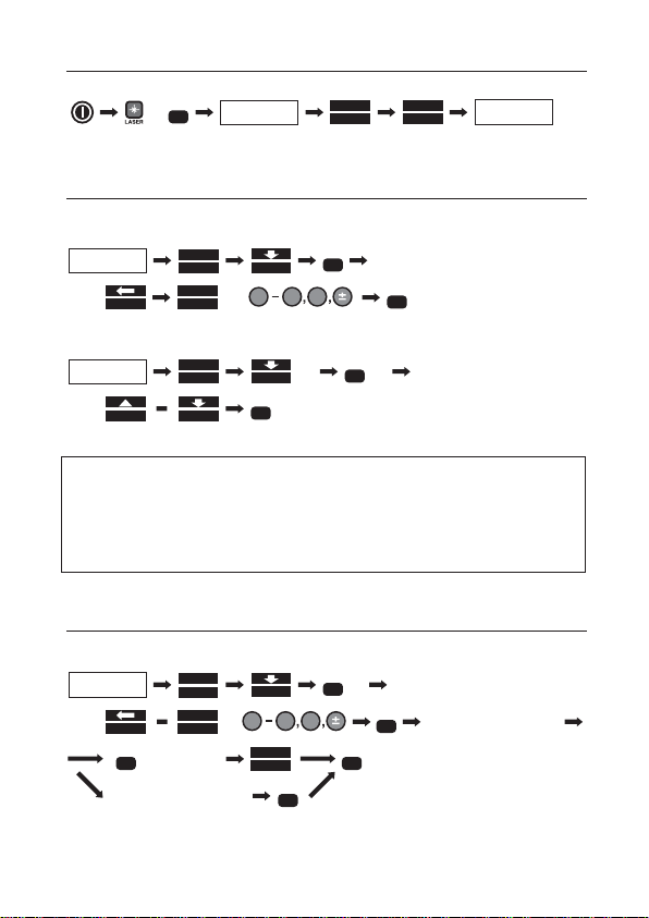
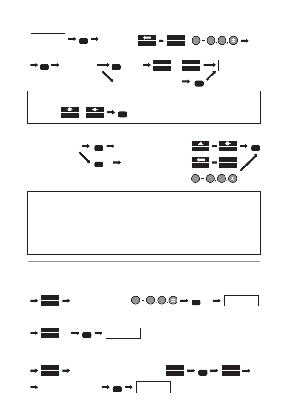
1. Starting Special Function
2. Creating / Selecting a Job File
To create a new job file:
Or to select a job file:
NOTE: Once a job file is created or selected, it is effective until a
new job file is created or another job file is selected.
The default job file "PENTAX" is provided permanently
so that data is stored even when no user defined
job file exists.
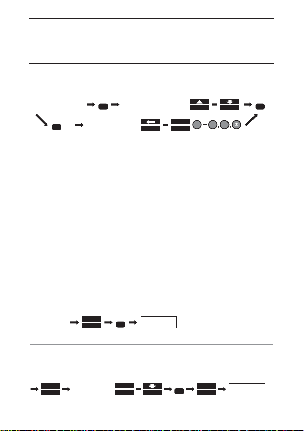
3. Input a Known Point Coordinate
To input and store a known point coordinate;
or
ENT
POWER TOPO LITE
MAIN MENU
FILE
F1
F4
input a new job name by using
F1
TO 123
F5
0.9
DEF
,
ENT
POWER TOPO LITE
MAIN MENU
FILE
F1
F4
x2
x2 select a job file by
ENT
F1
F4
ENT
POWER TOPO LITE
MAIN MENU
VIEW
F3
F4
input a Point Name by using
F1
TO 123
F5
0.9
DEF
,
x2
ENT
repeat to input value
ESC
SAVE
F1
ESC
to quit
x2
ENT
input PC (point code)
ENT
ESC
MODE A SCREEN
MODE
S. FUNC
F5
F1
POWER TOPO LITE
MAIN MENU
10
NOTE: There are other functions in VIEW menu; Graphical View,
Edit Rectangular Data, and Edit Polar Data. For detail of
these functions, please refer to the instruction manual of
PowerTopoLite.
To input PC (point code):
NOTE: PC list is displayed only when point codes are stored in
the job named “PointColeList”. “PointCodeList” job can be
created by the procedure described in the section 2, and
PC can be stored by inputting PN and PC as a point
coordinate data. PC list can be also transferred from a
computer.For more detail,refer to the instruction manual
of PowerTopoLite.
A new point code can be input and memorized as a point
coordinate data, but it is not stored as the data of
“PointCodeList”. If a new PC need to be added to the list,
select “PointCodeList” job and add a PC as a new
Rect.Coord.Data.
4. Rectangular Coordinate Measurement
4.1 Station Point Setup
To select from the memory:
ENT
ENT
select a PC
from the list by
input a new PC by
move cursor to PC
F1
F4
ENT
x2
F1
TO 123
F5
0.9
DEF
POWER TOPO LITE
MAIN MENU
MEAS
F2
ENT
STATION POINT
SETUP
H. ANGLE
SETUP
LIST
F2
F5
ACCEPT
select
the point by
F2
FIND PN
F4
ENT
11
Or to input the station point information:
NOTE: The input item (cursor position) may be selected by
To input PC (point code):
NOTE:
Input items are PN (point name), X, Y, Z, IH (instrument
height), and PC (point code).
If the input PN already exists in the memory, then the corresponding
point information
(coordinate & point code) is displayed in the screen.
The result of Free Station, prior to stakeout, is automatically
set in each field of Station Setup.
4.2 Orientation (Station Point H.Angle Setup)
To input a given angle:
Or to set the angle 0°:
Or to calculate by the Back Sight Point:
STATION POINT
SETUP
0.9
DEF
input Point
Name by
F1
TO 123
F5
ENT
,
H. ANGLE
SETUP
repeat to
input value
ENT
ESC
SAVE
F1
to quit
ENT
input PC (point code)
or
F5
ACCEPT
F3
F4
ENT
,
move cursor to PC
ENT
ENT
select a PC from the list by
input a new PC by using
F1
F4
ENT
x2
F1
TO 123
F5
0.9
DEF
,
MEASUREMENT
SCREEN
0.9
DEF
input value by using
INPUT
F2
ENT
x2
MEASUREMENT
SCREEN
0 SET
F1
ENT
x2
MEASUREMENT
SCREEN
input value or select from the list
BSP
F5
ENT
LIST
F2
F5
ACCEPT
aim Back Sight Point
ENT

12
4.3 Measurement
To select the Target type:
NOTE: You can check the selected target type at the left side
of the Battery mark in the top line of the screen.
To measure:
Or to start tracking:
NOTE: EDM measurement mode can be changed by
To input the point information:
To save the point information:
Or to measure and save:
NOTE: the Point number is automatically incremented or
decremented to make rapid continuous measurements
possible.
repeat
PAGE
F5
TARG ET
F2
PAGE
F5
x2 until the desired target
type is selected
MEASF1MEAS
F1
x2
PAGE
F5
x2
EDM
F1
select and change the EDM mode
0.9
DEF
move cursor by
F3
F4
ENT
,
RETURN TO THE
MEASUREMENT
SCREEN
repeat to input value
ENT
ESC
to quit
ENT
input point code
F5
ACCEPT
EDIT
F4
,,
F1
TO 123
F5
input values by using
SAVE
F2
(next measurement)
ME/SAVE
F3
(next measurement)

13
4.4 Offset Measurement
For Radial Offset (the horizontal distance offset along the line of
measurement):
For Tangential Offset:
For Distance Offset (slope distance):
NOTE: The Offset values are cleared once the measurement is
saved.
4.5 Remote measurement
To enter the Remote mode:
or
MEASUREMENT
SCREEN
0.9
DEF
input value
by using
PAGE
F5
OFFSET
F2
ENT
ENT
ESC
F5
ACCEPT
RETURN TO THE
MEASUREMENT
SCREEN
MEASUREMENT
SCREEN
0.9
DEF
x3
PAGE
F5
OFFSET
F2
ENT
,
ENT
RETURN TO THE
MEASUREMENT
SCREEN
F4
input value by using
MEASUREMENT
SCREEN
0.9
DEF
x2
PAGE
F5
OFFSET
F2
ENT
,
ENT
RETURN TO THE
MEASUREMENT
SCREEN
F4
input value by using
ESC
F5
ACCEPT
MEASUREMENT
SCREEN
x2
PAGE
F5
REMOTE
F1
PAGE
F5
x2
MEAS
F1
RETURN TO THE MEASUREMENT
VALUES ARE UPDATED BY
TURNING THE TELESCOPE
EDIT
F4
Input PN, PH
ESC
F5
ACCEPT
SAVE
F2
(next measurement)
ENT
input PC
MEASUREMENT
SCREEN
MEAS
F1
PAGE
F5
REMOTE
F1
x2
REMOTE MODE
MEASUREMENT VALUES ARE
UPDATED BY TURNING THE
TELESCOPE
EDIT
F4
Input PN, PH
ESC
F5
ACCEPT
SAVE
F2
(next measurement)
ENT
input PC

14
NOTE: Remote values are calculated based on the assumption of
the reference plane.Three types of the reference plane are
available in PowerTopoLite; Cylindrical surface, Fixed plane
(default) and Rotated plane.
To change the reference plane type:
To quit the Remote mode:
5. Polar Coordinate Measurement
5.1 Station Point Setup
To input the point information:
NOTE: Input items are PN (point name), IH (instrument height),
PC (point code), TEMP (temperature), PRESS (atmospheric
pressure) and ppm. "TEMP" and "PRESS" can be input only
when "Atmospheric Correction" is set to "ATM INPUT".
"ppm" can be input only when "Atmospheric Correction"
is set to "ppm INPUT".
The input item (cursor position) may be selected by
POWER TOPO LITE
MAIN MENU
x2
PAGE
F5
PREF
F4
F4
x4
F4
ENT
select by using
F3
,
ENT
PAGE
F5
REMOTE
F1
x2
MEASUREMENT
SCREEN
F5
ACCEPT
MEAS
F2
F4
STATION POINT
SETUP
POWER TOPO LITE
MAIN MENU
ENT
ENT
input Point Name by
0.9
DEF
,
F1
TO 123
F5
ENT
repeat to input value
H. ANGLE
SETUP
ESC
SAVE
F1
to quit
ENT
or confirm “ppm”
F4
F3
,
ENT

15
5.2 Orientation (Station Point H.Angle Setup)
Only when the orientation of the horizontal angle is required,
proceed according to the following procedure.
Otherwise, just pass this step by
To input a given angle:
Or to set the angle 0°:
Or to calculate by Inverse:
5.3 Measurement
To select the Target type:
NOTE: You can check the selected target type just at the left of the
Battery mark in the top line of the screen.
To measure:
Or to start tracking:
NOTE: EDM measurement mode can be changed by
input value by using
0.9
DEF
INPUT
F2
ENT
MEASUREMENT
SCREEN
x2
0 SET
F1
ENT
MEASUREMENT
SCREEN
x2
INVERS
F5
ENT
MEASUREMENT
SCREEN
select Start Point from the List
LIST
F2
ENT
F5
ACCEPT
LIST
F2
select End Point
from the List
ENT
F5
ACCEPT
ENT
x2
PAGE
F5
x2 repeat until the desired
target type is selected
TARG ETF2PAGE
F5
MEAS
F1
MEAS
F1
x2
PAGE
F5
x2
EDM
F1
select and change the EDM mode
ENT

16
To input the point information:
To save the point information:
Or to measure and save:
NOTE: The point number is automatically incremented or
decremented for rapid continuous measurements.
5.4 Offset measurement
For Radial Offset (horizontal distance offset along with the line of
measurement):
For Distance Offset (slope distance offset):
NOTE: The Offset values are cleared once the measurement
is saved.
ENT
input
Point Name by
0.9
DEF
,
F1
TO 123
F5
ENT
repeat to input value
RETURN TO THE
MEASUREMENT
SCREEN
ESC
to quit
ENT
Input PC
EDIT
F4
F5
ACCEPT
(next measurement)
SAVE
F2
(next measurement)
ME/SAVE
F3
input value
by using
MEASUREMENT
SCREEN
ENT
PAGE
F5
RETURN TO THE
MEASUREMENT
SCREEN
OFFSET
F2
0.9
DEF
ENT
ESC
F5
ACCEPT
input value by using
MEASUREMENT
SCREEN
ENT
PAGE
F5
RETURN TO THE
MEASUREMENT
SCREEN
OFFSET
F2
0.9
DEF
ENT
ESC
F5
ACCEPT
(point
code)

17
6. Free Stationing
6.1 Known Point setup
Select the point from the stored data:
Or input PN which is already stored in memory to call and display the
known coordinate.
6.2 Measurement
Select the target type and measure:
NOTE: You can check the selected target type just at the left of the
Battery mark in the top line of the screen.
To proceed to the next point:
Repeat "6.1 Known Point Setup" and "6.2 Measurement" for all known
points.
6.3 Calculation
input Inst. Height (IH) by using
0.9
DEF
ENT
FREE
F4
POWER TOPO LITE
MAIN MENU
KNOWN POINT
SETUP
select the point by
LIST
F2
MEASUREMENT
SCREEN
F2
FIND PN
F4
ENT
F5
ACCEPT
repeat
TARG ET
F2
until the desired target type is selected
MEAS
F1
KNOWN POINT
SETUP
ENT
ADD
F1
input
Point Name
CALC
F5
MEASUREMENT
SCREEN
RETURN TO
POWER TOPO LITE
MAIN MENU
ENT
F5
ACCEPT
ENT
ENT
ESC
to quit
ENT
Input PC
SAVE
F1
(point
code)

18
NOTE: The result of Free Station is automatically carried
forward to the station setup of Rectangular coordinate
measurement and stakeout.
7. Stake Out
7.1 Station Point Setup
Select from the stored data:
Or input PN which is already stored in the memory to call and display
the known coordinate.
NOTE: The result of Free Station, prior to stakeout,is
automatically set in each field of Station Setup.
7.2 Orientation (Station Point H.Angle Setup)
To input a given angle:
Or to set the angle 0°:
Or to calculate by the Back Sight Point:
POWER TOPO LITE
MAIN MENU
ENT
PAGE
F5
STAK
F1
STATION POINT
SETUP
H. ANGLE
SETUP
ENT
LIST
F2
F2
FIND PN
select the point by
F4
F5
ACCEPT
STAKEOUT
COORD. SETUP
ENT
INPUT
F2
input the value x2
STAKEOUT
COORD. SETUP
ENT
0 SET
F1
x2
STAKEOUT
COORD. SETUP
ENT
BSP
F5
select the point by
F2
FIND PN
F4
F5
ACCEPT
ENT
LIST
F2

19
7.3 Stakeout Point Setup
Select the point from the stored data:
7.4 Stakeout Measurement
Check the designed value. If “COMPARE METHOD” is set to “LARGE
CHARACTER” press to proceed to the Stakeout screen
Turn the instrument until "DH.Angle" reads to "0".
Select the Target type:
NOTE: You can check the selected target type just at the left of the
Battery mark in the top line of the screen.
To measure in Tracking mode:
To confirm the position of the stake:
To proceed to the next point:
STAKEOUT
MEASUREMENT
ENT
BSP
F5
select the
point by
F2
FIND PN
F4
F5
ACCEPT
repeat
TARG ET
F2
until the desired target type is selected
MEAS
F1
x2 (move the target until “DH.dist” reads “0”)
MEAS
F1
To quit measurement
(position the target accurately)
PAGE
F5
F1
RECT. M
MEAS
F1
EDIT
F4
Input PN, PH and PC
SAVE
F2
ESC
RETURN TO STAKE-
OUT MEASUREMENT
SCREEN
NEXT
F4
STAKEOUT
MEASUREMENT
(repeat from “Stakeout Point Setup)
SCROLL
F3
LIST
F2

20
8. Stake Out (Point to Line)
"Point to Line" gives the distances between SOP and Int.P, A and Int.P,
B and Int.P.
8.1 Station Point Setup
Select the point from the stored data:
NOTE: The result of Free Station, prior to stakeout,is
automatically set in each field of Station Setup.
8.2 Orientation (Station Point H.Angle Setup)
To input a given angle:
Or to set the angle 0°:
Or to calculate by the Back Sight Point:
POWER TOPO LITE
MAIN MENU
ENT
STAK
F1
F4
PAGE
F5
STATION POINT
SETUP
select the point by
F2
FIND PN
F4
F5
ACCEPT
POINT A SETUP
ENT
INPUT
F2
input the value x2
POINT A SETUP
ENT
BSP
F5
select the point by
F2
FIND PN
F4
F5
ACCEPT
POINT A SETUP
ENT
0 SET
F1
x2
ENT
LIST
F2
A Int. P
B
SOP
LIST
F2
ENT
H. ANGLE
SETUP

21
8.3 Point A Setup
To input values:
Or to select from the memory:
8.4 Point B Setup
To input values:
Or to select from the memory:
8.5 Point To Line Measurement
To select the Target type:
NOTE: You can check the selected target type just at the left of the
Battery mark in the top line of the screen.
ENT
input Point Name by
0.9
DEF
,
F1
TO 123
F5
ENT
repeat to
input value
POINT B SETUP
ESC
to quit
ENT
Input PC (Point Code)
SAVE
F1
or
F5
ACCEPT
POINT B SETUP
ENT
LIST
F2
select the
point by
F2
FIND PN
F4
F5
ACCEPT
ENT
input Point Name by
0.9
DEF
,
F1
TO 123
F5
ENT
repeat to
input value
MEASUREMENT
ESC
to quit
ENT
Input PC (Point Code)
SAVE
F1
or
F5
ACCEPT
MEASUREMENT
ENT
LIST
F2
select the
point by
F2
FIND PN
F4
F5
ACCEPT
repeat
TARG ET
F2
until the desired target type is selected

22
To measure in Tracking mode:
To confirm the position of the stake:
9.Traverse Measurement
Traverse Measurement is based on the following assumptions:
• The current station is the foresight point of the previous station.
• The back sight point of current station is the previous station.
Limitations are:
• More than one traverse route can not be measured at the
same time.
• Do not store other data while you are measuring the
traverse route.
• When one traverse route is finished,perform the traverse
calculation before you store other data.
• Do not turn the power supply off until the measurement at
one start point or at one corner point is completed.
• Do not escape from the MEASURE screen.
• The same PN should not be used in one Job.And the PN can not
be overwritten in the traverse.
• The same traverse route can not be calculated again.
• Polar coordinates data of back sight and station points can not
be seen in the POLAR EDIT function, but it is sent properly in
SEND POLAR DATA function.
MEAS
F1
x2 (move the target to the desired position)
MEAS
F1
To quit measurement
(position the target accurately)
PAGE
F5
F1
RECT. M
MEAS
F1
EDIT
F4
Input PN, PH and PC by
SAVE
F2
ESC
RETURN TO STAKE-
OUT MEASUREMENT
SCREEN
F5
ACCEPT
x2

23
To start Traverse:
9.1 Measurement at the start point
Start the traverse from the start point measurement.
Station Setup:
Orientation (Station Point Setup):
or to set the angle 0°:
or to calculate by the known points (Start point and End point):
Side shot measurement:
POWER TOPO LITE
MAIN MENU
PAGE
F5
TRAV
F1
TRAVERSE
MENU
x2
TRAVERSE
MENU
ENT
STATION SETUP
ENT
input Point Name by
0.9
DEF
,
F1
TO 123
F5
ENT
repeat to input value
H. ANGLE
SETUP
ESC
to quit
or confirm “ppm”
input value by using
0.9
DEF
ENT
INPUT
F2
x2
SIDE SHOTS
x2
ENT
0 SET
F1
SIDE SHOTS
LIST
F2
select Start Point from the List
F5
ACCEPT
select End Point
from the List
INVERS
F5
ENT
ENT
F5
ACCEPT
LIST
F2
ENT
ENT
x2
SIDE SHOTS
EDIT
F4
for all side shots
MEAS
F1
repeat
,
SAVE
F2
,
MEAS
F1
finish measurements by
EDIT
F4
,
,
ENT
at the
Corner Point
ESC
TRAVERSE
MENU
F5
ACCEPT
F5
ACCEPT

24
NOTE: The corner point is the foresight of the traverse, which is
the next instrument point and must be ended by
If required, select the target by before each
measurement.
9.2 Measurement at a Corner Point
Station Setup:
NOTE: Input Instrument Height (IH), if necessary.
Orientation:
Side shot:
NOTE: The corner point is the foresight of the traverse, which is
the next instrument point and must be ended by .
If required, select the target by before each
measurement.
ENT
x2
TRAVERSE
MENU
ENT
F4
(the last corner point is displayed as Station)
(sight the back sight point)
ENT
ACCEPT
F5
EDIT
F4
for all side shots
MEAS
F1
repeat
,
SAVE
F2
,
MEAS
F1
finish measurements by
EDIT
F4
,
,
ENT
at the
Corner Point
ESC
TRAVERSE
MENU
PAGE
F5
TARG ET
F2
PAGE
F5
x2
TARG ET
F2
ENT

25
9.3 To finish the traverse measurement
Fixed traverse: Measure the known point and press at the last
corner point.
Closed traverse: Measure the start point and press at the last
corner point with the different Point Name.
NOTE: Use a different point name (PN) when you measure the
start point as the last corner point. For example, change
“T1” to “T1-1” etc.
Open traverse: The closing errors are not calculated.No need to end
the measurement by pressing .
9.4 Traverse Calculation
To Start Fixed traverse calculation:
NOTE: To select CLOSE TRAVERSE CALC.:
To select OPEN TRAVERSE CALC.:
Start Point Coordinate setup:
or to input the known coordinate;
ENT
ENT
ENT
TRAVERSE
MENU
ENT
F4
F4
F4
x3
x4
END POINT SETUP
ENT
LIST
F2
select the
point by
F2
FIND PN
F4
F5
ACCEPT
ENT
input Point Name by
0.9
DEF
,
F1
TO 123
F5
ENT
input the next value or
END POINT SETUP
ESC
to quit
F5
ACCEPT
x2

26
End Point Coordinate setup: the same operation as in the above.
NOTE: The End Point Coordinate Setup is required only in the
fixed traverse.
Result of Traverse Calculation:
To see the result of each corner point:
To see all points in order:
To save all results:
10. Cogo
To access COGO menu and select calculation type:
Input required parameters:
Save the result:
The required calculation parameters and the output are as follows
(p27):
F2
F1
or
F4
F3
or
F5
ACCEPT
TRAVERSE
MENU
PAGE
F5
POWER TOPO LITE
MAIN MENU
CALC
F2
ENT
select calc.
type by
F4
F3
or
ENT
input parameters by
terminating with
F5
ACCEPT
or
ENT
each time
RESULT SCREEN
ENT
input point name and point code
F5
ACCEPT
RETURN TO
PARAMETER SCREEN
ENT

27
Direction Angle (SP->EP)
H,V,S Distance
Coordinate of the
unknown point
Coordinate of centerpoint
of the arc,Radius of the arc
Coordinates of intersect
points (P1, P2)
Coordinate of the
intersect point
Coordinates of intersect
points (P1, P2)
Coordinate of the
intersect point of the line
and a perpendicular line
from the offset point.
Distance of the intersect
point from the SP of the
line
Coordinate of the offset
point
Coordinate of the offset
point
1
2
3
4
5
6
7
8
9
Inverse
Point
Coordinate
Circle Radius
Line-Arc
Intersection
Line-Line
Intersection
Arc-Arc
Intersection
Distance
Offset
Point Distance
Offset
ARC Distance
Offset
SP (Start Point)
EP (End Point)
CO (Known point coordinate)
DI (Distance to the unknown point)
BE (Direction Angle to the unknown point)
Coordinates of three points (P1, P2, P3)
SP (Start point of the line)
EP (End point of the line)
CP (Center point of the circle)
R (Radius of the circle)
S1 (Start point of the 1st line)
E1 (End point of the 1st line)
S2 (Start point of the 2nd line)
E2 (End point of the 2nd line)
C1 (Center Point of the 1st circle)
R1 (Radius of the 1st circle)
C2 (Center Point of the 2nd circle)
R2 (Radius of the 2nd circle)
SP (Start point of the line)
EP (End point of the line)
OP (Offset Point)
SP (Start point of the line)
EP (End point of the line)
DI (Distance on the line from SP)
OD (Offset distance from the line)
SP (Start Point of the arc)
EP (End point of the arc)
R (Radius of the arc)
DI (Distance on the arc from SP)
OD (Offset distance from the arc)

28
11. Area Calculation
To start area calculation:
To return to the calculation menu screen:
NOTE: This function calculates the length of 2D and 3D contour of
a polygon, and the 2D surface (area) of the polygon.
The polygon is defined by selecting points in such a way
that the contour segments of the polygon do not intersect.
The last selected point is automatically tied to the first
selected point to form the closed figure.
There are several function keys for point selection, such as
"ALL", "FIND PN", FROM", "TO", and "ORDER". Refer to the
instruction manual on the CD-R.
12. 3D Surface and Volume Calculation
To start Volume calculation:
PAGE
F5
POWER TOPO LITE
MAIN MENU
CALC
F2
ENT
select points of the polygon by repeating select (
F4
F3
or
ENT
F4
) and
F1
ACCEPT
RESULT SCREEN
ESC
x2
RESULT SCREEN
CALCULATION
MENU SCREEN
PAGE
F5
POWER TOPO LITE
MAIN MENU
CALC
F2
ENT
select points of the polygon by repeating select (
F4
F3
or
ENT
F4
) and
F1
ACCEPT
RESULT SCREEN
VOLUME
input the reference height by
0.9
DEF
ENT
RESULT SCREEN
CONTOUR
SURFACE AREA
ENT
x2

29
To return to the calculation menu screen:
NOTE: This function calculates the contour, the 2D and 3D surface
area, and the volumes (positive, negative and total.)
The order of point selection is not important. The number
of points must be less than 350. The 3D polygon is
automatically defined by the element triangles that are
formed by connecting neighboring points. The positive
and negative volumes are calculated based on the reference
height.
13. REM (Remote Element Measurement)
To start REM:
Measure the Reference point:
Measure the elevation of the remote point:
To return to Calculation menu:
ESC
x2
RESULT SCREEN
CALCULATION
MENU SCREEN
PAGE
F5
POWER TOPO LITE
MAIN MENU
CALC
F2
F4
ENT
x3
MEAS
F1
ENT
input prism (or reference) height
ENT
aim the point to be measured
REM VALUE IS
DISPLAYED AT THE
BOTTOM OF THE SCREEN
ESC
CALCULATION
MENU SCREEN
x2

30
14. RDM (Remote Distance Measurement)
To start RDM:
Measure the Reference point:
Measure the 2nd point (Target Point):
Measure the 3rd point (Target Point):
To change the reference to the present point:
To return to PowerTopoLite Main menu:
15. VPM (Virtual Plane Measurement)
To start VPM:
Station point setup:
RESULT SCREEN
ENT
POWER TOPO LITE
MAIN MENU
PAGE
F5
POWER TOPO LITE
MAIN MENU
VPM
F3
STATION POINT
SETUP
select the
point by
LIST
F2
H. ANGLE
SETUP
ENT
F2
FIND PN
F4
F5
ACCEPT
PAGE
F5
POWER TOPO LITE
MAIN MENU
RDM
F4
MEASURE THE
REFERENCE POINT
EDIT
F4
input the target height by
0.9
DEF
ENT
MEAS
F1
(select target if necessary)
MEAS
F1
RESULT SCREEN
DISTANCE FROM THE
REFERENCE POINT
MEAS
F1
RESULT SCREEN
DISTANCE FROM THE
REFERENCE POINT
VER.
F5
RESULT SCREEN
DISTANCE FROM THE
PREVIOUS TARGET POINT
RESULT SCREEN
DISTANCE FROM THE
PREVIOUS TARGET POINT
ENT
x2 (repeat reference point measurement)

31
H.angle setup:
To input a given angle:
Or to set the angle 0°:
Or to calculate by the Back Sight Point:
Measure three points to define the plane:
Virtual plane measurement:
To return to PowerTopoLite Main menu:
16. Changing Preference
To access Preference menu:
Preference List (page 32)
input the value by
0.9
DEF
INPUT
F2
ENT
x2
THREE POINTS
MEASUREMENT
0 SET
F1
ENT
x2
THREE POINTS
MEASUREMENT
LIST
F2
Input value or select from the List
BSP
F5
F5
ACCEPT
ENT
SAVE
F1
or
THREE POINTS
MEASUREMENT
if necessary,
MEAS
F1
SAVE
F2
ENT
(repeat measurements
of remaining two points)
VPM SCREEN
if necessary,
SAVE
F2
aim a point on the plane
ESC
VPM SCREEN
POWER TOPO LITE
MAIN MENU
PREF
F4
select an item by
PAGE
F5
F4
ENT
F3
or
POWER TOPO LITE
MAIN MENU
POWER TOPO LITE
MAIN MENU
x2
select an option by
F4
F3
or
ENT
F5
ACCEPT

32
1
2
3
4
567
8
9
10
Language
COORD.AXIS
INPUT METHOD
ACTION METHOD
REMOTE METHOD
COMPARE METHOD
REQUEST AIMING
EDM SETTINGS
ELEV.FACTOR
DUPLICATE PN CHK
DISP.1 NAME
DISP.2 NAME
DISP.3 NAME
DISP.1 AXIS
DISP.2 AXIS
DISP.3 AXIS
ROTATION
PRIM. MEAS KEY
SEC. MEAS KEY
SHOT COUNT
SHOT INPUT
AVE.ELEV.
SCALE FACT.
ENGLISHXYZBASE DIRECTION
RIGHT ANGLE
HEIGHTCW10 KEY SYSTEM
(ABC)
PROCESS TYPE
FIXED PLANE
ALL IN ONE INFO.
OFF
MEAS SHOT
TRACK CONT
1 time
01 times
0m
1.0
OFF
Your Language
Any alpha-numeric character
Any alpha-numeric character
Any alpha-numeric character
RIGHT ANGLE, HEIGHT
BASE DIRECTION, HEIGHT
BASE DIRECTION, RIGHT ANGLE
CCW
STRUCTURE TYPE
CYLINDER FACE, ROTATED PLATE
LARGE CHARACTERONMEAS CONT,TRACK SHOT,TRACK CONT
TRACK SHOT, MEAS CONT, MEAS SHOT
3 times, 5 times,INPUT
01-99 times
-9999.999m - +9999.999m
0.00000001 - 1.99999999
ON
Axis labels that are
displayed in 1st line,2nd
line, and 3rd line.
Orientation direction of
each axis.
Direction of H.angle
measurement
Operational procedure
type
Stake Out screen
"AIM" message ON/OFF
Dist. Meas.mode for 1st
MEAS key
Dist. Meas.mode for 2
nd
MEAS key
Item Default Options Remark
Preference List
10 KEY SYTEM (123), FULL TEMPLATE, DIVIDED TEMPLATE,
MATRIX SYSTEM

34

Member symbol of the Japan Surveying
Instruments Manufacturers’
Association representing the high quality
surveying products.
Printed in Belgium
Total Surveying Solutions
011106
PENTAX Industrial Instruments Co., Ltd.
2-5-2 Higashi-Oizumi
Nerima-ku,Tokyo 178-8555, Japan
Tel.+81 3 5905 1222
Fax +81 3 5905 1225
E-mail: international@piic.pentax.co.jp
Website: www.pentax.co.jp/piic/survey
www.pentaxsurveying.com
Japan Surveying Instruments Manufacturers’ Association
 Loading...