

Page 1

Instruction
Manual
Instruction Manual
Total Construction Solutions
PENTAX Industrial Instruments Co.,Ltd.
2-5-2 Higashi-Oizumi / Nerima-ku, Tokyo 178-0063,Japan
Tel.+81 3 5905 1222 / Fax +81 3 5905 1225
E-mail:international@piic.pentax.co.jp
Website:www.pentax.co.jp/piic/survey
www.pentaxsurveying .com
PLP-601
PLP-602
PLP-601R
Automatic Self-leveling Laser
Automatic Self-leveling Laser
Automatic Self-leveling Laser
PLP-602R
Automatic Self-leveling Laser
Page 2

Page 3
3
Safety Precautions (must be followed)
The following items are intended to prevent possible injury to the user or
other people and/or damage to the instrument.
These safety precautions are important to the safe operation of this
product and should be observed at all times.
•
Distinctive Displays
The following displays are used to distinguish precautions by the
degree of injury or damage that may result if the precaution is ignored.
WARNING
Items indicated by this indication are precautions which,if ignored,
could result in death or serious injury.
CAUTION
Items indicated by this indication are precautions which,if ignored,
may result in injury or material damage.
• The term ‘injury’here refers to injuries such as cuts,bums or elec tric
shock,the treatment of which will not likely require hospitalization or
longterm attention.
• ‘Material damage’refers to damage to facilities,buildings,acquired
data,etc.
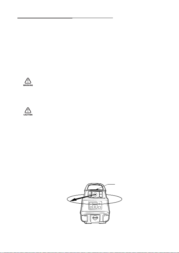
1.For safety in handling this laser
product,operate it according to the
instructions shown on the warning
label,the location of which is shown
in the following illustration.
3.Laser is emitted
from here and this
part is rotated.
2.Laser warning label
The label is put on the ceiling.
Page 4

4
WARNING
• While the instrument is operating,be careful not to expose your
eyes to the emitting laser beam (red light source).Exposure to a
laser beam for a long time may be hazardous to your eyes.
(Laser beam:Equivalent to class 2 Laser level)
• Do not try to dismantle the instrument.Have it repaired by your
dealer or authorized repair shop.Dismantling it by yourself may
worsen the trouble.
CAUTION
• Do not stand on the carrying case.The case could turn over
causing the person standing on it to fall.
• When attaching the instrument to a tripod,make sure the
instrument is securely fixed to the tripod and then securely
tighten the tripod leg clamps.If not securely fastened and/or
tightened,the main unit could fall off or the tripod could fall over.
• When carrying the tripod,be careful so that the tripod shoes do
not strike anyone.
• When setting the tripod,make sure not to stab someone’s hand
or foot with the tripod shoes.
• Operate this laser product with the height of laser avoiding that
of eyes of car drivers and pedestrians.
Avoid putting the laser on a highly reflective material such as mirror.
When disposing of this instrument,take a measure such as
breaking the battery cap so that the laser will not be emitted.
Page 5
5
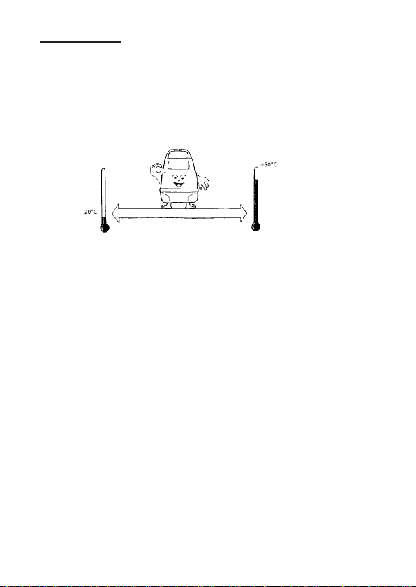
Precautions
The instrument should not be stored or used in extreme temperatures or
job on a place subject to rapid change of temperature.
(Refer to the ambient temperature range) The instrument may not
function properly if used out of the ambient temperature range.
Page 6

6
Put into the carrying for storage and place in a dry area not subject to
vibration,dust or high moisture.
When storage and usage temperatures are widely different,leave the
instrument in the case until it can adjust to the surrounding temperature.
Page 7
7
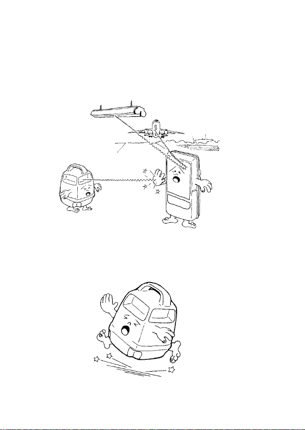
The detector (option) may react to the Laser beam and further react to
the Fluorescent lamp,Site lamp,modulated light or an electric wave
(in or near the airport etc.) and so correct measurement is sometimes not
performed near these places.In these cases,please measure again after
stopping or cutting these modulated light or wave etc.
The instrument should be transported or carried carefully to avoid
impact or vibration.
Page 8

8
The instrument should be stored in the carrying case and packed with
cushioning material and handled with care as ‘Fragile’.
Check the ‘check and adjustment of the datumpoint’ of page 35 in this
manual and be sure to check to see if error exists before the instrument
is used.After the instrument has been stored a long time or it has
suffered an impact or vibration,be sure to check to see if trouble exists
before use.If any trouble exists,adjust or have it repaired.
Page 9

9
Be sure to observe the items in the instruction manual for proper use
of the instrument.
Please replace attached batteries with new ones before you work
because their voltage may be low.
Page 10

10
CONTENT
Safety Precautions
Precautions
• 1. For proper use of the instrument 11
1.1 Standard configuration
1.2 Description
1.3 Unpacking
1.4 Battery inser tion
• 2. Display and Keypad 17
2.1 Keypad
2.2 Role of keys
2.3 Warning display
• 3. Preparation for measurement 22
3.1 Setting up the tripod
3.2 Setting up the instrument
3.3 Arranging the detector
• 4. Measurement 26
4.1 Operating the instrument
4.2 Operating the detector:LS3
• 5. Maintenance and adjustment 33
5.1 Maintenance after use
5.2 Check and adjustment of the datum point
5.3 Troubleshooting
• 6. Specifications 39
• 7. Notice to the user of this product 40
Page 11

11
1. For proper use of the instrument
1.1 Standard configuration
The instrument (PLP-601 / PLP-602 /PLP-601R / PLP-602R)
Detector (LS6)
Rod Adapter (LA6)
D type battery (PLP-601 / PLP-602)
Charger (PLP-601R / PLP-602R)
Rechargeable Ni-MH battery built in the body (PLP-601R / PLP-602R)
Carrying Case
Instruction Manual
1
2
3
4
5
6
7
8
Page 12

1.2 Description
12
Center mark
Top handle
Emitting beam aperture
Keypad
Detachable knob for
Rotor
Battery cap
Bottom plate
Page 13
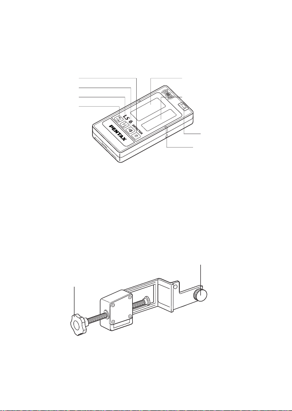
13
Plate Vial
Beam Reception Window
LCD Display
Illumination Switch
Buzzer Switch
Accuracy Switch
Power Switch
Index
Fixing Knob
Detector Attaching Screw
Rod Adapter LA6
Page 14
14
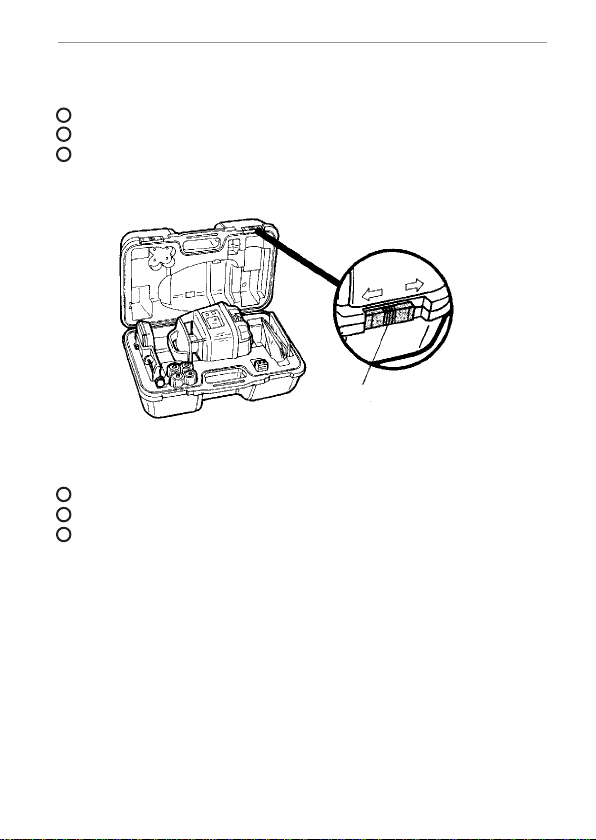
1.3 Unpacking
Taking the instrument out of the carrying case
Gently set down the carrying case so that its cover is upward.
Unlatch and open the case while pushing the latch lock.
Remember how the instrument is placed in the case before
removing it.
Putting the instrument into the carrying case
Set down the carrying case and open the cover
Gently put the instrument into the case
Close the case and secure the latch
NOTE:
• When taking out the instrument,be sure to secure it with your hands.
• When putting the instrument into the case, be sure to turn the power
switch off.
• If the case cover is difficult to close,check again whether or not the
instrument is properly inside the case.
1
2
3
1
2
3
Latch
Page 15

15
1.4 Battery insertion
Battery insertion for the instrument
Turn the detaching knob for battery cap counterclockwise and remove
the cap from the instrument.
Insert 4 pcs D type batteries into the battery box according to its
(+) and (-) marks.(PLP-601 / PLP-602)
While holding the instrument with one hand,push the battery cap into
the battery box and attach it by turning the knob clockwise.
1
2
3
Page 16

16
Battery insertion for the detector
LS6 Detector
Slide the battery cover while pushing its mark and remove it.
Insert the accumulated dry battery into the battery holder according
to its (+) and (-) marks.
Slide the battery cover to reinsert it.
CAUTION:
• Pay attention to the battery holder’s (+) and (-) marks for proper
battery insertion.
• Batteries must be of the same type. D o not use a combination of
batteries whose remaining capacity differs.
1
2
3
Rear View of LS6
Accumulated Dry Battery (6F22)
Battery Cover
Page 17

17
2.Display and Keypad
2.1 Keypad
2.2 Role of keys
(1) Power supply key
ONON
OFFOFF
BATTERY
CHECK POWER
OFF
LEVEL
MANUAL
MODE
Battery check key
Remaining battery display lamp
Auto/Manual
change key
Manual mode
display lamp
Off level
display lamp
Power
supply key
ON
OFF
BATTERY
CHECK POWER
OFF
LEVEL
MANUAL
MODE
ONON
OFFOFF
BATTERTERY Y
CHECKCHECK POPOWERWER
OFFOFF
LELEVELVEL
MANUMANUALAL
MODEMODE
Off level display lamp
Power
supply key
Pushing power supply key begins
the automatic self-leveling.
The off level display lamp blinks in
red during activating the leveling.
The blink interval becomes longer
gradually as the leveling comes
near to completion.
The color of the off level display
lamp turns to green when the
leveling is completed,a rotor
begins to rotate and then a laser
beam is emitted horizontally.
The lamp (green) is turned of
about 5 seconds later after the
leveling completion.
1
2
3
Page 18

18
(2) Battery check key
Remaining battery display lamp
NOTE:
• When 4 pcs rechargeable batteries type D are used,only 2 green
lamps are turned on even if they are fully charged.
The consumption status of a
battery can be confirmed by the
remaining battery display lamp
when the battery check key is
pressed after turning on the power
supply.
The remaining battery display
lamp is turned off about
15 seconds later after the battery
check key is pressed.
1
2
Turning on 3 green lamps
Turning on 2 green lamps
Turning on 1 green lamp
Blink of 1 red lamp
Turning on 1 red lamp
Workable enough.
Remaining capacity is little.
Prepare the spare battery.
Battery is to be replaced.
Replace the battery.
ON
OFF
BATTERY
CHECK POWER
OFF
LEVEL
MANUAL
MODE
ONON
OFFOFF
BATTERTERY Y
CHECKCHECK POPOWERWER
OFFOFF
LELEVELVEL
MANUMANUALAL
MODEMODE
Off level display lamp
Battery check key
Page 19

19
(3) Auto/manual change key
NOTE:
• Simple grade setting can be done by manual mode, but usually
performed without stopping the automatic self-leveling function
(without pressing the Auto/manual change key).
During the manual mode,the horizontal accuracy of emitted laser
beam is not guaranteed.
• During the manual mode, the manual mode display lamp is turned on
in red.
When the Auto/manual change
key is being pressed for more than
2 seconds,the manual mode
display lamp is turned on in red.
The automatic self-leveling begins
and the automatic self-leveling
function stops after completion of
automatic leveling.
During the manual mode,the laser
beam is emitted even if the
instrument is tilted largely
(out of correction area).
When the Auto/manual change
key is pressed again,the manual
mode display lamp is turned off,
the manual mode is reset and
returns to normal function.
1
2
3
4
ONON
OFFOFF
BATTERTERY Y
CHECKCHECK POPOWERWER
OFFOFF
LELEVELVEL
MANUMANUALAL
MODEMODE
Manual mode display lamp
Auto/manual change key
Page 20

20
(4) Switching the rotation speed
• Please switch the rotation speed after turning off the instrument
power supply.
[From 300 to 600 rpm]
NOTE:
• When the instrument is set to 600 rpm,the Manual mode display lamp
and off level display lamp blink in red for a few seconds after power
supply is turned on.
• Rotation speed is set to 300 rpm on factory shipping.
Push the power supply key while
pushing the Auto/Manual change
key.
Manual mode display lamp and off
level display lamp blink in red a
few seconds and tell that the
rotation is switched to 600 rpm.
The switched rotation speeds is
memorized even if power supply is
turned off.
Turn off the power supply and
then push the power supply key
while pressing the battery check
key to return to 300 rpm.
1
2
3
4
ONON
OFFOFF
BATTERTERY Y
CHECKCHECK POPOWERWER
OFFOFF
LELEVELVEL
MANUMANUALAL
MODEMODE
Manual mode display lamp
Auto/manual change key
Off level display lamp
ONON
OFFOFF
BATTERTERY Y
CHECKCHECK POPOWERWER
OFFOFF
LELEVELVEL
MANUMANUALAL
MODEMODE
Battery check
Power
supply key
Page 21

2.3 Warning display
Off level display lamp turns on in red as warning display and rotation of
rotor and emission of laser beam stop under following situation.
(1) When the instrument is tilted more than ± 5.7°(± 10%) then
power supply is turned on
Turn off the power supply and install the instrument horizontally
(within ± 5.7°) and turn on the power supply again.
(2) When some shock is added to the instrument while at work
Turn off the power supply and turn on the power supply again.
• If the work is to be continued,per form this procedure after resetting
the laser beam at the “reference mark”.
(3) When,status that the automatic self-leveling function does not
become stable continues for about 3’after power supply is turned on
Turn off the power supply and turn on the power supply again.
But warning is displayed farther,change the setting place of
instrument or stop the construction machines which may be the cause
of vibraton.
NOTE:
• After warning is displayed (Off level display lamp turns on in red),if no
key is pressed for about 10’,power supply is turned off automatically.
• At above (2), warning display does not work while automatic
self-leveling function stops (Off level display lamp turns on in red).
21
ONON
OFFOFF
BATTERTERY Y
CHECKCHECK POPOWERWER
OFFOFF
LELEVELVEL
MANUMANUALAL
MODEMODE
Off level display lamp
Page 22

22
3. Preparation for measurement
1.1 Setting up the tripod
[Arranging the tripod]
Prepare the normal tripod for Level instrument.
The dome head type and elevation type tripod for Level instrument
can be used.
[Selection of the place to set up the tripod]
Be sure to select a place where the job will not be interrupted and
the instrument can be set to have almost same distance to each
point to be measured.
1
2
Extraction
Nearly horizontal
Page 23

23
[Setting up the tripod]
For an extension tripod,adjust the legs to a suitable length and secure
the leg clamps.
Spread the legs to a proper extent for the tripod head to be nearly
level and push them into the ground.
Should the tripod head be off level,adjust it by expanding the legs
accordingly.
NOTE:
• For a tripod setting place,be sure to select a place where the ground
or floor has less vibration and there is no fear of upset.
• To set the tripod on a slippery floor,the legs must be secured.
Use a chain (or similar) to keep the legs from spreading.
1
2
3
Page 24

24
3.2 Setting up the instrument
[Mounting on the tripod]
Mount the instrument on the tripod head and while supporting the
instrument with one hand,secure it using the tripod center screw.
NOTE:
• Also when removing the instrument from the tripod,loosen the
center screw while supporting the instrument with one hand.
• Do not leave the instrument mounted on tripod without the center
screw being tightened.It may cause the instrument to fall and be
damaged.
Instrument
Tripod head
Center screw
Page 25

25
3.3 Arranging the detector
[Installing the rod adapter LA6]
LS6 detector
Mount the instrument on the rod adapter so that the guide pin of the
rod adapter is inserted into the guide hole in the back of the detector.
Tighten the attaching screw of the rod adapter into the detector.
NOTE:
• The rod adapter is to be used when the detector is used together with
a staff or plain rod.
1
2
Rod Adapter
Fixing screw
Detector
Page 26

26
4. Measurement
4.1 Operating the instrument
[Starting the operation]
Press the power supply key.
Automatic self-leveling function works and leveling begins
automatically.When leveling is completed,the rotor begins to rotate
and emits invisible laser beam.
NOTE:
• Before operating the instrument, per form the ‘Check and adjustment
of the datum point’on page 35.
• Before operating the instrument,confirm that the manual mode display
lamp is not turned on in red. While automatic self-leveling function,
(the manual mode display lamp turns on in red) pay attention that
the horizontal accuracy of emitted laser beam is not guaranteed.
• When the status that the automatic self-leveling function is not stable
continues for about 3’,the off level display lamp turns on in red and
rotation of rotor and the emission of laser beam stop.
•
While not in operation,be sure to turn the instrument’s power switch off.
WARNING
• While the instrument is operating, be careful not to expose your
eyes to the emitting laser beam (red light source).Exposure to a
laser beam for a long time may be hazardous to your eyes.
(Laser beam:Equivalent to class 2 Laser level)
ON
OFF
TERY Y
CHECKPOPO
WER
OFF
VEL
MANUALAL
MODE
1
2
OFF
Manual mode
display lamp
Auto/Manual
change key
MANU
MODE
BATTER
CHECK
LELEVEL
ON
WER
OFF
Off level
display lamp
Power
supply key
Page 27

27
4.2 Operating the detector:LS6
[Power switch]
Push the power switch to turn on the power to the detector.
Pushing the power switch again turns off the power.
NOTE:
• The liquid crystal displays all light up as shown in the above figure with
the power switch pressed.This permits checking for any defects in the
liquid crystal display.
• The battery’s remaining capacity is always indicated with the power
turned on.Check when to replace the battery,referring to the figure
on the above.
• The power turns off automatically if no laser beam is received and any
key not operated for about ten minutes.To turn on the power again,
push the power key once again.
1
2
6
Page 28

28
[Selecting the reference level detecting accuracy]
Push the detection accuracy selection switch to select the needed
detection accuracy.
High accuracy detection:
To be selected for detecting the reference level with accuracy.
Low accuracy detection:
To be selected if high accuracy is not needed or when stable reference
level cannot be obtained due to slight vibration at job site.
NOTE:
• For the detection accuracy to be selected,check with the mark in the
liquid crystal display (see the figure on the above).
• The detection accuracy alternates each time the detection accuracy
selection switch is pressed.
• High detection accuracy is initiated when the power turns on.
• If the point to be measured is distant, the reference level may not be
displayed stably by the influence of heat waves shimming or the
instrument slightly vibrating.Under such conditions,
select ‘Low detection accuracy’.
High accuracy
Low accuracy
Page 29

29
[ON or OFF of the beam reception buzzer]
Push the beam reception buzzer switch to select either the buzzer
sounding or silenced.
[Illuminating the display]
Push the illumination switch to illuminate the display.
Pushing the switch again turns off the illumination.
NOTE:
• For either the buzzer sounding or silencing to be selected,check with
the mark in the liquid crystal display (see the figure on the above).
• The buzzer sounding/silencing alternates each time the buzzer switch
is pushed.
• The buzzer sounding is initiated when the power turns on.
• The illumination turns off automatically if no laser beam is received
and any switch is not operated for about one minute.
To illuminate the display again,push the illumination switch once more.
1
2
6
6
Page 30

30
[Detecting the reference level]
At the measuring point,set the position of the detector nearly to the
height of the beam emitting aperture of the instrument.
Position the detector where the buzzer sound (or the beam reception
display appears) by directing the detecting display nearly toward the
instrument and moving the detector up and down.
Move the detector up and down again according to the beam
reception display (or the buzzer) and obtain the reference level.
NOTE:
• When detecting the reference level, the detector should face the
instrument in the range of about 40°,to the right and left from
the front.
Move the detector down as it is positioned high.
The buzzer sound beeps at short intervals.
This is the reference position.
The buzzer sound beeps continuously.
Move the detector up as it is positioned low.
The buzzer sounds lasting beeps intermittently.
Page 31

31
[Direct marking]
After the reference level has been detected, mark a line along the
detector’s index,or its top or bottom end.
[Plain rod marking]
After the reference level has been detected, mark a line along the plain
rod’s top or bottom end.
NOTE:
• If a line was marked along the detector’s top or bottom end,be sure to
make measurement compensation as described on the back of the
detector.
• The detector should previously be positioned correctly on the plain rod
according to the reference mark.
[Plain rod marking]
After the reference level has been detected, mark a line along the plain
rod’s top or bottom end.
6
Page 32

32
[Reading the staff]
After the reference level has been detected, read the staff,using the
index on the rod adapter.
NOTE:
• When detecting the reference level,slightly loosen the fixing screw for
the rod adapter and move the detector up and down along the staff.
Staff
Index
Rod Adapter
Page 33

33
5. Maintenance
5.1 Maintenance after use
[Stains on the main body]
Brush dust off and wipe off moisture with tissue paper.
Clean off any stains with a soft,dry cloth.
Excessive stains should be removed with a soft cloth soaked in a water
diluted neutral detergent and squeezed dry.
Do not use benzine,thinner,gasoline or chemicals.
[Stains on the glass surface]
Brush dust off.
Gently wipe off stains with a silicone cloth or a cleaning cloth for eye
glass lenses.
Excessive stains should be wiped off with soft cotton cloth
impregnated with a cleaning liquid for eye glass lenses.
1
2
3
Page 34

34
[Handling the battery]
If the instrument is not to be used for a long time,be sure to remove
the batteries from the instrument and the detector and store them.
NOTE:
• Be sure not to use chemicals such as benzine, thinner or gasoline.
• Be careful not to scratch the glass surface.
• Leaving the batteries in the instrument for extended period may cause
power consumption even if it is not in use.
• If used battery is left in the battery holder,the instrument of the
detector may be damaged by the battery fluid leakage.
leakage
Page 35

35
5.2 Check and adjustment of the datum point
[Check]
Set up the instrument on the tripod halfway between two walls or
pillars about 40m away so that the ‘X side’of the instrument faces the
‘Wall A’ and level it.
Operate the instrument and turn on the power to the detector.(use the
detection accuracy initially set.)
Mark the reference point detected for both walls.(A,B)
Arrange a pair of target plates (with the same scale) and fix them to the
walls (A and B) so that the center values of the target plates coincide
with the reference point marks.
Loosen the center screw of the tripod to turn the instrument 180 for
the ‘X side’to face the ‘Wall B’and tighten the center lock screw again
for the instrument to be leveled again.
1
2
3
4
5
Over view
(Keypad)
X side
Page 36

36
Read the target plates on the walls (A,B) to detect the reference points.
If the readings of the target plates differ less than ±5 mm, the
instrument needs not to be adjusted.
If more than ± 5 mm,proceed to the following (Adjustment)
procedure.
6
7
8
Wall A Wall B
X side in 1 X side in 5
Target
Detector
Appr. 20m Appr. 20m
Page 37

37
5.3 Troubleshooting
PLP-601 / PLP-602 / PLP-601R / PLP-602R
Rotor Display Content Checking point
Display lamps are Battery capacity Replace with fresh
not turned on. is low. batteries or charge
battery
Incorrect battery Check the polarity
insertion. of the batteries.
Lamp turns on. Instrument’s tilt Turn off the power
exceeds auto leveling supply and reset the
area.(± 5.7°) instrument level
Instrument is tilt (±5.7°) and turn on
largely by any cause. again.
After power supply Turn off the power
turns on,unstable supply and turn on
state of auto again.
self-leveling function Turn off the power
continues supply and turn on
approx.3 min. again.
NOTE*
Lamp & lamp Defect of instrument Turn off the power
blink mutually itself. supply and turn on
again.If the lamps blink
farther, instrument need
to be repaired.
*
NOTE:
• When the operation is continued,set the laser beam on the reference
mark and perform it.
Does not rotate
ONON
OFFOFF
BATTERTERY Y
CHECKCHECK POPOWERWER
OFFOFF
LELEVELVEL
MANUMANUALAL
MODEMODE
Manual mode display lamp:
Off level display lamp:
3
1
1
2
2
1
1
2
2
1
3
2
1
2
1
Page 38

38
Detector LS6
Rotor Display Content Checking point
Can rotate Cannot detect Battery capacity Replace with fresh
is low. battery.
Incorrect battery Check the polarity
insertion. of the batteries.
Can rotate Battery indicator Battery capacity Replace with fresh
blinks is low. battery.
NOTE:
• If the instrument is not returned to normal,even through these
measures,connect your dealer or authorized shop.
1
1
2
2
Page 39

39
6. Specifications
INSTRUMENT PLP-601R / PLP-602R
Accuracy of reference beam: ±10”(PLP-601/PLP-601R)
± 12” (PLP-602/PLP-602R)
Measuring range: Radius 1~200m (PLP-601/PLP-601R)
Radius 1~120m (PLP-602/PLP-602R)
Automatic self-leveling range: ± 10% (± 5.7°)
Light source: Visible Laser Diode (635nm Max 1.0mW)
Rotation speed: 300rpm / 600rpm (can be switched)
Operation power supply: 4 x D type batteries (PLP-601/ PLP-602)
Rechargeable Ni-MH battery (PLP-601R/ PLP-602R)
Operation time: 24 hours on manganese battery (PLP-601/PLP-602)
48 hours on alkaline battery (PLP-601/PLP-602)
18 hours on Rechargeable Ni-MH battery (PLP-601R/PLP602R)
Charging time: 2 hours (PLP-601R/ PLP-602R)
Waterproof: IPX6 Watertight type
Working temperature range: -20°C ~+50°C (-4°F ~ +122°F)
Tripod attaching screw: JIS/B type (5/8”x 11 thread)
Dimensions: 170w x 170D x 225H mm
Weight: 2.5kg (w/battery)
DETECTOR LS6
Detection Accuracy: HIGH ± 1mm LOW ± 2.5mm
Beam reception indicator: Liquid crystal display / buzzer
Sensitivity of vial: 30’/ 2mm
Power supply voltage: DC9V battery(6F22 or 6LF22)
Operation time: Approx 40 hours on alkaline battery (6LF22)
Auto power off: Power supply:Approx.10 min.
Illumination: Approx.1 min
Dimensions: 140w x 68H x 25L mm / 200g
Page 40

40
7. Notice to the user of this product
To assure compliance with the Safety Standard 21 CFR,Chapter I.
Subchapter J.The U.S.bureau of Radiological Health requires the
following information to be provided to the user:
1) Specifications of Laser Radiation.
A. This laser system is designed and built to have a GaAIAs laser
diode radiating at 635nm ± 15 nm.
B. Radiant power
This laser product is designed and built to radiate a maximum
average radiant power of 10µW as scanning beam during
functional operation.The user may be subject to this radiation as a
scanned beam while the rotor is rotating until such time that the
instrument is turned off.
•
For a period of less than 10 seconds during the operation the
user may be subjected to this radiation.
2) The following labels are affixed to and must remain attached to
this laser product.
A. Certification Label
‘This laser product conforms to the provisions of 21 CFR 1040.10
and 1040.11.For a class 2 laser product.’
Located on the surface of the base of top-handle.
B. Caurion Label
‘Laser beam,do not look into the laser beam source directly.’
Located near to exit aperture,facing upward.
3) Caution to maintain the safety in compliance with the standard.
•
To maintain the safety standard,refrain from any operation,maintenance or adjustment other than described in this instruction manual.
•
Operation,maintenance or adjustment other than those specified in
this instruction manual may result in hazardous radiation exposure.
•
Maintenance and repair not covered in this manual must be done by
an authorized Pentax dealer.
Page 41

41
Page 42

Page 43

Page 44

Member symbol of the Japan
Surveying Instruments Manufacturers’
Association representing the high quality
surveying products.
Printed in Belgium
Total Surveying Solutions
PENTAX Industrial Instruments Co.,Ltd.
2-5-2 Higashi-Oizumi
Nerima-ku,Tokyo 178-0063,Japan
Tel.+81 3 5905 1222
Fax +81 3 5905 1225
E-mail:international@piic.pentax.co.jp
Website:www.pentax.co.jp/piic/survey
Japan Surveying Instruments Manufacturers’ Association
 Loading...