

Page 1
SERVICE MANUAL
(Version 03)
High-end Video Processor
PENTAX EPK-i
Medical Instrument Division / Service Technical Group
MNL-045-03 / May 16, 2008
Page 2

< CONTENTS>
1. Specifications Page 1
2. General explanations Page 2
Feature
3. Functions Page 3
4. Configuration (Main parts) Page 6
5. Precaution Page 7
6. Service Page 8
6.1 Lamp block
6.2 Pump Page 10
6.3 Iris Page 13
6.4 Peripheral Board (G700) Page 14
6.5 Process Board (H700) Page 15
7. Electrical safety test Page 18
7.1 Dielectric strength test
7.2 Protective GNDing wire resistance
7.3 Leakage current test Page 19
8. Trouble shooting Page 20
9. Wiring Diagram Page 21
Appendix – Exploded view
Parts list
Notes for using this Service Manual
1) Up-date of Service Manual will be notified by such information as Notice of Modification,
Service Note and so on.
2) When you start repair servicing, be sure to leave service records.
3) This Service Manual voids preceding "New Product Repair Guide" for the same model, if any.
4) Upon request, PENTAX will provide qualified service personnel with further information to
service this product provided that the requested information needed within the range of
servicing described in this Service manual.
Page 3
Photo
-
1 New label
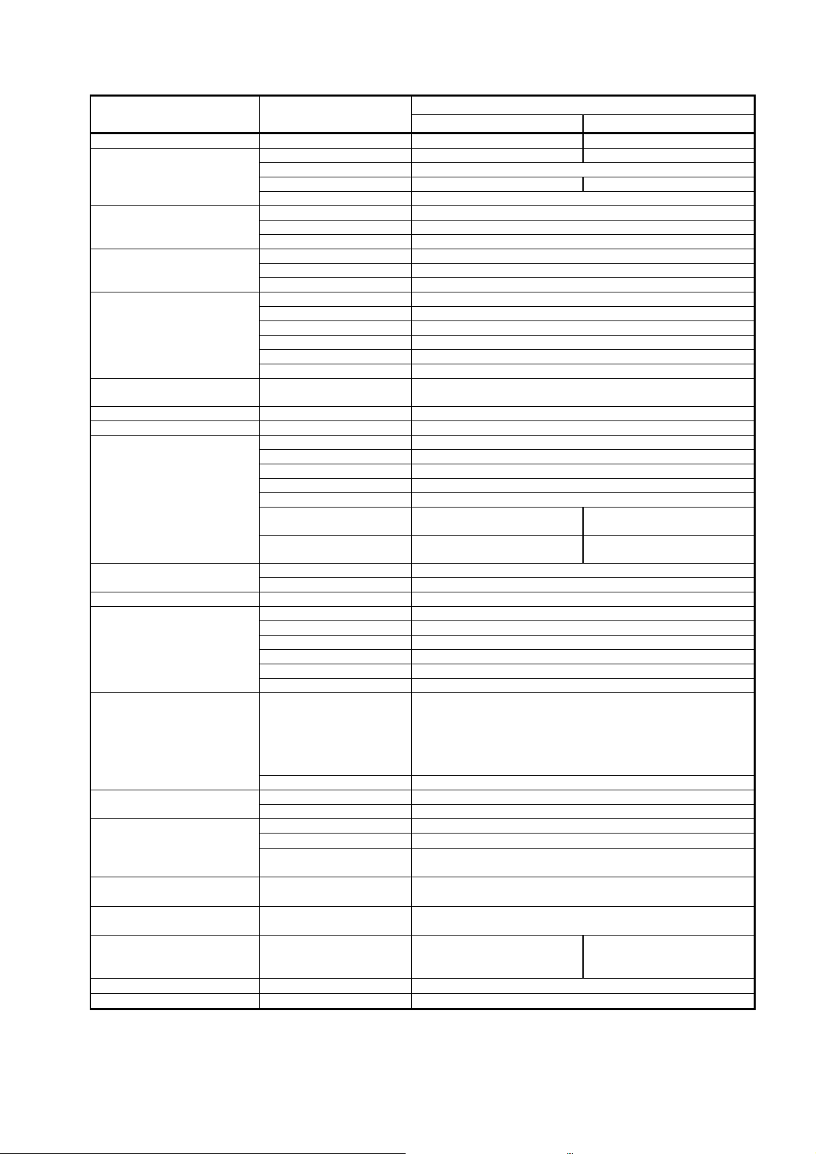
1. Specifications
Item
Video system NTSC PAL
Power requirement
Operation environment
Storage environment
Illumination
Scope compatibility
Color correction Red and Blue each adjustable by +/- 5 steps each
White balance Adjustable automatically with “White Bal” button
Video signal
Digital output
Audio input Analog input Stereo mini plug x 1
Control signal
Air feeding
LCD touch screen
Classification electro
medical equipment
Electromagnetic
Interference
Harmonic current
Medical electrical
equipment general
requirement for safety
Size Dimensions 430mm (W) x 485mm (D) x 205mm (H)
Weight Main body 26.5Kg
Description
Voltage 120VAC 230VAC
Frequency 50 - 60Hz
Power consumption Less than 5.4A Less than 2.8A
Voltage fluctuation +/-10%
Temperature 10 – 40 ℃
Relative humidity 30 – 85 %
Atmospheric pressure 700 –1060 hPa
Temperature -20 – 60 ℃
Relative humidity 0 – 95 %
Atmospheric pressure 700 – 1060 hPa
Lamp 300W Xenon lamp
Lamp average life span Continuous use, Average 500 hours
Color temperature 6,000K
Iris control Automatic / Manual
Brightness control Adjustable by +/- 5 steps each
Auxiliary lamp 3W White LED (IEC60825-1)
PENTAX Color Video Endoscope i-series and K-series
DVI-D, DVI-A DVI x 1 terminal (either DVI-D or DVI-A is assigned)
RGBS output 9pin D-sub x 2
Y/C output S terminal x 2
Composite video output BNC connecter x 1
DV output DV terminal x 1
Printer output N. A.
Analog input BNC connector x1
Serial output USB A terminal (Female) x 2 (for memory, printer)
LAN RJ45 terminal x 1
RS-232c 9pin D-sub x 1
Remote Stereo mini plug x 3
Keyboard 6-pin Mini-DIN x1 (exclusive or ordinary PC keyboard)
Footswitch 4pin Bayonet lock type(Female) x 1
Water feeder (SA-P2) 4pin Bayonet lock type(Female) x 1
Sync signal (Y signal) BNC connector x 1
Level 1: 2.0 – 2.8 L/min.
Control
Air pressure 45 – 70 KPa
Display 6.4 inch TFT
Touch screen Pressure-sensitive type
Electric shock protection
Degree of protection BF type
Degree of explosion
proofing
Electromagnetic
compatibility
emissions
Table-1 Specifications
Level 2: 2.9 – 3.4 L/min.
Level 3: 3.5. – 4.0 L/min.
Level 4: 4.1 – 4.5 L/min.
Level 5: 4.6 – 7.2 L/min.
Do not use in potentially flammable surroundings.
120V model 230V model
On / Off, Air flow volumes are selectable in 5 steps
Complied with IEC60601-1-2 Class B
Complied with IEC60601-3-2 Class A
UL60601-1 IEC60601-1
Specification
(K-series with Y/C output)
9pin D-subx1,
S terminal x1
S terminal x1,
BNC connector x1
Class – I
- 1 -
Page 4

2. General explanations
The PENTAX EPK-i is a high-end Video Processor, which produces High Definition images with a
specially developed scope “Mega Scope 90i”. Several image processing methods (advanced
enhancement, etc.) that help the user observe precisely and easily have been introduced. At the same
time, the EPK-i keeps compatibilities with the former K-series scopes (Y/C signal type). To obtain stiller
frozen images, a m echanical structure (rotary shutter etc,) has been built in. A user-friendly manner has
been established with several new devices.
Features
1) High Definition image> High Definition im ages can be created with “Mega Scope 90i” wh ich has a
2) Advanced Enhancement> In addition to the ordinary image enhancement (Edge enhancement),
3) Still and Fine Freeze> Thanks for the progressive scan method on the mega pixel CCD and the
4) LCD Touch panel>As an operational panel, an LCD touch screen panel has been introduced. T he
5) SA-P2 port>The exclusive port for the water jet supplier SA-P2 is available on the back panel of
6) Lamp>The lam p (300W xenon lamp) c an be replaced by a lamp cartridge (OL-X25) by the user
mega pixel CCD. The 90i scope pr ovides the image data in digital signal to the EPK-i. The EPK-i
can process the image signal without converting the analog signal. The EPK-i has a DVI (Digital
Visual Interface) output port . Therefore non deteriorated image can be seen on the PENTAX LCD
monitor (when “DVI-D” port of the monitor is used. / For analog signal, “VGA” port is also available
on the monitor). The DVI port can provide either DVI (digital sig nal) or VGA (analog signal)
depending on “DVI Output” setting of the system (refer to the Owner’s Manual). The default setting
is “VGA”. When the f ull digital environment is used, “DVI Output” must be set to “DVI”. Otherwise
the image will not appear on the monitor.
Note: PENTAX LCD monitor will be launched soon.
A summery for the monitor connec tor, exclusive cable and “DVI Output” setting are shown in the
table below:
Connector on LCD monitor
DVI-D
VGA
Note: The connectors shown in the table are male.
Because DVI signal is ver y fast, the DVI cab le is limited to 3m. With a longer cable, the image
becomes noisy as oppos ed to the image on the analog CRT monitor becoming darker with an
analog longer cable.
Surface Enhancement and Contrast Enhancement are available. Both enhancement modes cannot
be used simultaneously. The other one will be disabled.
rotary shutter of the EPK-i, stiller and finer images can be captured. Because of the progressive
scanning the captured image is real as opposed to the compensated or interpolated image f rom the
field scanning. The finer image is attributed to the progressive scanning. Meanwhile the rotary
shutter controls the exposure time. The shorter th e exposure time is, the s tiller the frozen image
becomes. However as the side effect the image becomes darker. Together with the ordinary iris, the
rotary shutter controls the e xposure time as short as possible and so that the luminance becomes
enough for the acceptably brighter and stiller image. During the progressive scan, the next light
comes through the hole of the rotary shutter. Thus another mechanical shutter interrupts the light.
This shutter is driven by a solenoid motor and momentarily closes. As a result of the stiller freeze,
mechanical parts are increased. H owever no adjustment or it is easy if any.
EPK-i has a single boar d computer inside. Thus it takes about one and half minutes by the LCD
touch panel is ready for the operation. The LCD touch panel reacts by pressure, which is a sensitive
device. Do not operate it with a sharp edge. The lamp, pump and white balance switches are
independent from the single board computer. It means the lamp can be turned on and the pump
works with level-1 before the system has been up and running. The LCD touch screen has a
function that an image put from “VIDEO IN” port is displayed.
the EPK-i. When the scope button or the foot switch assigned with function “WJ” is pressed, an
open-collector, active-low signal is sent to the SA-P2 to turn on and off.
(refer to the Owner’s Manual). The door of the lamp house can be opened without any special tool.
This door activates the interlock switch for AC power of the unit when it is completely closed. The
lamp cartridge consists of the lamp, two heat sinks and IR cut filter. Trained service engineers are
allowed to replace the lamp itself (The Service manual for the EPK-i will be issued soon. Please
refer to it in detail).
Connector of cable DVI Output setting
DVI
VGA
- 2 -
Page 5

7) Pump>Air feed volume can be changed in five levels with the touch screen panel. The air feed
volumes of each level are set with the special Set up menu (It is a hidden menu to customers).
When the peripheral board (G700) is replaced for the pump func tion repair, the former setting value
can be reused without measuring the air f eed volume with an air flow meter. When the pump is
replaced, the air feed volumes of each level will be adjusted with the menu by measuring the air
feed volume with the air flow meter. The peripheral board is attached with a small tube from the
pump. It has been prepared for the precise air feed control, however it is not currently working. But
if it is detached, the air must leak at this point. As a result, the air won’t be fed from the air outlet.
8) Auxiliary lamp>3W while light LED has been introduced as an auxiliary lamp. When the main lamp
ignition failure continues for about 8 seconds, t he auxiliary lamp automatically comes into the light
axis by the solenoid motor.
9) DC Power supply for patient circuit>The DC power supply unit for the patient circuit exists
independently from the DC power supply unit for the secondary circuits. However the input of the
DC power supply unit for the patient circuit is connected to the DC output of the DC power supply
unit for the secondary circuits. The reason why the DC po wer supply units individually exist is just
due to limited spaces of the EPK-i unit inside.
10) Lamp power supply unit>The main unit and the igniter exist individually. Of course they are
connected each other. However they can be treated as a spare part independently.
11) Scope detector>A limit switch has been attached just beside the scope connector assembly. When
the scope handle is turned clockwise to lock the scope connector, the switch is activated and the
system recognizes that the scope has been connected completely.
12) Processor ID>The processor model name “EPK-i” and its serial number have been stored as ID.
These information must be necessary for the LAN environment.
13) Serial and LAN port>Using an USB memory device or LAN, system modification can be done
easily.
14) XLUM and Manual mode>Both modes act as an iris manual mode. On the basis of the
concepts that “XLUM” is for confirming the location of the scope distal tip and “Manual” is for
observing the specific parts in vivo in iris manual mode, these modes are available
independently.
3. Functions
1) Preprocess Board (J700)
1)-1 Image signal processing> Because the EPK-i can accept all types of the K-series scopes,
Preprocess board has a function that can process the three kinds of the image signals such as
R-Y/B-Y color differential signal (old 30/40 series), Y/C signal (30/40 or 70/80 series ) and LVDS
signals (90K and 90i series).
R-Y/B-Y and Y/C signals (anal og) are converted into 10 bit YUV signal with the video decoder/ADC
(U16).
The 20 bit YUV signal is sent to the FPGA (U23) and converted into 12 bit YCbCr signal.
Finally the 12 bit YCbCr sig nal is sent to Process board (H 700) through the connector CN13 on
Mother board(E700).
As for LVDS signal, DO+/DO- (LVDS: Low Voltage Differential Signal) is sent to the
serializer/deserializer (U42) to be serialized into 12 bit (90i scope) or 8 bit (90K scope) LVDS signal.
The LVDS signal is sent to the also the FPGA (U23) to be converted into 12 bit YCbC r signal.
Finally the 12 bit YCbCr signal is sent to Process board (H700) through the connector (CN13) on
Mother board(E700) as well.
With 90i scope, the white balance is adjusted with the FPGA (U23). With the other scopes, the white
balance is adjusted with the control board in the scope.
1)-2 Iris signal> Depending on a scope, there are three kinds of signals from the scope that is used for
the iris control – “YIRI S” (90K scope), “Yout” (30/40, 70/80K scope) and “DO+/DO-“ (90i scope). And
there are two types of processing the iris control signals.
“YIRIS” or “Yout” signal is converted into 12 bit iris control signal with the AD converter (U56).
“DO+/DO-“ is converter into 12 bit iris control signal with the FPGA (U23).
Both converted signals are sent to Peripheral board (G700) through the connector (CN13) on
Mother board (E700).
1)-3 Patient circuit> Bec ause Preprocess board that is directly connected to the scope exchanges
signals with the scope, it has digital isolators that divides Preprocess board into the patient circuit
and the ordinary circuit.
2) Process Board (H 700)
2)-1 Image signal processing>This board receives 12 bit YCbCr signal from Preprocess board (J700)
through Mother board (E700).
- 3 -
Page 6

The 12 bit YCbCr signal is processed by enhancing or changing color with the front panel operation
with the FPGA (U2).
The processed YCbCr image sig nal is converted in to 10 bit RGB signal with the DSP (U2), and
sent to the FPGA (U39).
The 10 bit RGB signal is sent to Video process board (I700) through the connector (CN8) on Mother
board (E700) after gamma compensation with the FPGA (U39).
Meanwhile the same 10 bit RGB signal is converted into 8 bit RGB signal with the FPGA (U39).
The 8 bit RGB signal is sent to the digital display processor (U51) to be superim posed with
characters.
The 8 bit RGB signal with characters is sent to the two ways. On e is to the panel link transmitter
(U56) to be converted into the image signa l for DVI. And the image signal for DVI i s sent to I/O-1
board (L700) with the internal cable (B521).
The other one is sent to D/A converter (U59) to be converted into RGB analog signal for VGA. And
the RGB analog signal is sent to I/O-1 board (L700) with the internal cable (B522).
The digital display processor (U51) has function t o zoom up the image or to make a sub screen.
2)-2 Character generati on>The FPGA (U2) handles the keyboard operation.
The FPGA (U2) detects the character inputs a nd sends the instructions to the digital display
processor (U51) to create the characters.
The digital display processor (U51) generates the characters and merges them to the image signal.
The fixedly displayed texts like “Age” are stored in the memories connected to the FPGA (U2).
These texts are also merged to the image signal with the digital display processor (U51).
The FPGA (U2) also sends the instruction to the digital image processor on Video Board (I700) in
order to create appropr iate characters to meet the different display resolutio n.
3) Video Board (I700)
3)-1 Image signal processing-1>This board receives 10 bit RGB signal from Process board (H700)
through Mother board (E700).
The 10 bit RGB signal is convert ed into the 8 bit RGB signal and sent to the digital display
processor (U100, 102) to be merged with characters.
The 8 bit RGB with characters is sent to the digital video encoder (U3 03) through the FPGA (U301)
and encoded into RGB analog signal. Finally the signal is sent to th e RGB port x2 on th e back panel
through I/O-1 board (L700).
Also the 8 bit RGB with characters is sent to the digital video encoder (U310) through the FPGA
(U301) and encoded into Y/C analog signal. Finally the signal is sent to the Y/C port x2 on the back
panel through I/O-1 board (L700).
The same 8 bit RGB signal with characters is corrected with the FPGA (U301) in order to meet the
required printer color. The look-up-table in the FPGA (301) is used for the color compensation. The
corrected RGB signal is converted into RGB and Y/C analog signal with the digital v ideo encoder
(U317 and U324) and sent to the RGB or Y/C printer port on the back panel through I/O-2 board
(M700). Note: This port is not available with 120V model.
3)-2 Image signal processing-2>This board creates DV format image signal.
The 10 bit RGB signal is converted into the 8 bit RGB signal and sent to the digital display
processor (U100) to be merged with c haracters.
The 8 bit RGB with characters is sent to the DV encoder (U411) through the FPGA (U301) and
encoded into DV signal. Finally the signal is sent to the DV port on the back panel through I/O-2
board (M700). Audio picked up by the microphone attached to “Audio IN” port on the back panel is
converted into 4 bit digital signal and sent to the D V encoder (U411) to merge to the DV signal.
3)-3 Image signal processing-3>This board receives the outer video signal to superimpose it on the main
image.
Outer video image is accepted f rom “COMPOSITE-IN” port through I/O-2 board (M700).
The outer video signal is converted into 8 bit rec656 format signal with the video decoder (U208)
and sent to the digital display processor (U100).
The outer video signal is processed as picture-in-picture data with the digital display processor
(U100) and merged to the main image.
4) Peripheral Board (G700)
4)-1 Iris control> With every type of scope, the luminance signal is converted into the 12 bit iris signal on
Preprocess board(J700).
The 12 bit iris signal is sent to the FPGA (U19) to measure if the current iris position is adequate
against the brightness set by the front panel.
The digital signal controller (U12) creates the iris reference signal (analog) by referring to the results
measured with the FPGA (U19). The iris reference signal is sent to the iris analog circuit to control
the iris.
- 4 -
Page 7

4)-2 Rotary shutter c ontrol> To obtain a stiller frozen image, it is necessary to control an exposure time of
light. It is accomplished by adjusting the hole on Rotary shutter (M4). The parts related to Rotary
shutter consist of Rotary shutter (M4), Space motor (M6), Photo int errupter (PI1) and Shutter (M3).
These are controlled with Peripheral Board ( G700).
4)-3 Pump control> The pump control signal (Pump ON-OFF, Air flow level 1-5) are sent from the front
panel to Peripheral Board (G700) through Process Board (H700) to turn the pum p ON-OFF.
The pump control sign al is sent to the micro controller (U32) to turn the pump ON-OFF.
After the micro controller (U32), a part of the pump control signal is sent to the digital potentiom eter
to set the air flow level.
4)-4 Auxiliary lamp control> The lamp power supply unit sends the lamp failure signal to Peripheral Board
(G700) when the lamp ignition fails or the main lamp turns off unexpectedly.
The lamp failure signal from the lamp power supply unit is detected by Peripheral Board (G700) and
sent to the FPGA (U19).
The FPGA (U19) sends signals to Auxiliary lamp to move its LED lamp into the light axis and turn on
the LED lamp.
5) SBC Board (F700 / SBC: Single Board Computer)
5)-1 Touch Panel and LCD Display control> To control the capacitive type touch panel and manage the
various operation buttons and menu tabs.
5)-2 USB Memory control> When the image is captured with the setting that the image output has been
assigned to “SERIAL OUT1, 2” port, the captured image will be sent to the USB memory connected
to the port.
5)-3 Patient Data management> To provide the graphical user interface for the patient data and store the
data.
5)-4 Serial port control> To control the RS-232C port for “ENDONET ” database software.
5)-5 LAN control> To control the port for a local area network .
- 5 -
Page 8

Shutter
under cover plate
Covers for Card cage and
Igniter (IGN1)
Bypass Board (P700)
Iris Motor (M1)
Light Axis
4. Configuration (Main parts)
Preprocess Board (J700)
Power supply are available
Scope
Connector
Power Switch
Touch Panel
LCD Display
Front panel
Pump (PU1)
SBC (F700)
Peripheral Board (G700)
Process Board (H700)
Video Board (I700)
Card Cage on
Mother Board (E700)
DC-DC Converter (PS2)
Video Capture
Board (O700)
I/O-1 Board (L700)
I/O-2 Board (M700)
I/O-3 Board (N700)
Pointing blinded parts
Switching Power Supply (PS1)
Lamp Power Supply (LU1)
Interlock Switch (SW2)
Photo-1 EPK-i Main parts
Rotary Shutter
Lamp
Mechanical Block
Rotary Shutter
Main Motor (M4)
Rotary Shutter
Hole Control Motor (M6)
Iris
Auxiliary Lamp (LD1)
Shutter Solenoid (M3)
Auxiliary Lamp Motor (M7)
Fig-1 Mechanical block
- 6 -
Page 9

5. Precaution - Important
1) General
You have to take utmost care to follow the general rules and practice for safety in servicing electrical
medical equipment.
2) Power off before ser vicing
For electrical safety, make sure to disconnect the power cable before opening the cover.
3) Route of electrical wire
Be sure to keep the ori ginal routes of the electrical wires and the origina l positions of the cores.
Otherwise it may break the compatibility with the EMC regulation or may cause problems such as
lamp ignition failure. You must put the wires back to the or iginal routes after the maintenance. You
should take photos of the wires and cores beforehand.
4) High temperature on the lamp
Just after turning off the lamp it may be hot. Be careful not to suffer heat injuries when replacing a
lamp.
5) Electrostatic Discharge
To avoid damaging PCBs, wear anti-static protection such as a wr is tband and discharge the
electrostatic charge before servicing.
6) Disassembling parts
The procedures of disassembling the mechanical and electrical parts are not described in detail in the
service manual. Unless otherwise mentioned, detach from the outer parts to the inner parts or from the
upper parts to the lower parts. In the c ase a special technique is necessary, it is described. You can
refer to the exploded view pages as well.
7) Electrical safety test
Be sure to do the following tests when you did a repair by opening the cove, after putting back all of
the disassembled parts and the cover to the original position. The procedures are described in
following pages.
a) Dielectric strength test, b) Protective earthing circuit resistance, c) Leakage current test
- 7 -
Page 10

Screw x3
Hook
Heat sink
6. Service
Note: Refer to Photo-1 for the location of the parts to be replaced. And also refer to appendix pages for wire routing.
6.1 Lamp block
A way of replacing the lamp bulb and reusing the heat sink is described below.
Important: 1) This job must be done by a person who has got the service training for the EPK-i.
1) Take out the lamp block from the lamp hous e.
2) To detach the old lamp, unscrew the three screws and release the hook.
2) The IR cut filter cannot be reused, must be replaced together with the lamp bulb. A spoiled
filter may cause heat injury due to intensive light through the scope.
Rear Front
See Photo-2. Remove Front heat sink by rocking it.
Hint: It may be hard to detach Front heat sink and occasionally Filter ring
comes off attaching on the lamp bulb. In this case, put Filter ring back
to Front heat sink.
3) Replace the IR cut filter with a new one in the following order:
a) To remove Spring ring from the ditch in Filter ring, insert the tip of
the thin screw driver into the hole of Filter ring and push the end of
Spring ring toward the center a little b it and lift it by the tip of the screw
driver. See Photo-3 left.
Hint: If the end of Spring ring is not located at the hole of Filter ring, rotate
Spring ring by pressing the other end with a screw driver to be so.
Caution: 1) Do not apply excessive force to Spring ring when detaching it so as not to spoil it.
2) Spring ring may pop out when detaching it. Cover it by a palm.
Photo-2 Lamp block
b) Replace IR cut filter with new one without tainting nor scratching it.
Hint: Confirm if IR cut filter has settled horizontally in Filter ring.
c) Pinch both ends of Spring ring (shown by coloring in red) with two pairs of tweezes and then put
Spring ring into the ditch of Filter ring while narrowing the cut in Spring ring. See Photo-3 Right hand
side.
Hint: The opposite part (shown by coloring in green) against the cut in Spring ring should be put into the ditch of
Filter ring first and the rest of the ring will be put into the ditch subsequently.
Caution: Do not taint nor scratch IR cut filter while attaching Spring ring. If it is tainted, clean it carefully with
isopropyl alcohol solution. If it is scratched, discard it.
d) Confirm if IR cut filter and Spring ring have been attached correctly by waving Front heat sink. If a
click sound can be heard from IR cut filter, it is OK. If not, do it fr om scratch.
Filter
Screw driver
Hole of Filter ring
End of Spring ring
Filter ring
Front heat sink
Spring ring
IR cut filter
Spring ring
Photo-3 IR cut filter replacement
Tweezes
Narrow the cut
Tweezes
- 8 -
Page 11

IR cut filter
Grease
2 3 4 5 1
4) Apply heat sink grease (RM-3505) to the places on the new lamp bulb as shown in Fig-2 (①Side,
②Bottom,③Top side,④Top inside,⑤Filter ring inside). And assemble the lamp block in reverse
order of 2).
Hint: When fixing Front heat sink, adjust its angle by rotating it so that the lamp cartridge does not rock on
the flat top.
Caution: 1) Use only the lamp that PENTAX supplies, because PENTAX uses lamps that have a specific
ignition property and luminance.
2) It is not good to apply too much heat sink grease. This may cause lamp ignition failure. Apply
the grease so that the metal part can be seen under the grease.
3) When you apply grease, do not contaminate the top of the bulb and IR cut filter with the grease.
4) When you attach Front heat sink, pay attention to IR cut filter. Do not remove it. Do not
contaminate it with a finger print and so on. Do not scratch it.
5) Filter ring has a hole. The hole must come up (See Fig-2 Right hand side).
6) Screw the three screws and fasten the hook firmly. Otherwise it may cause lamp ignition failure.
Hole in Filter ring faces up
RM-3505
Fig-2 Places where heat sink grease applied
5) Attach the new lamp block firmly in the reverse order of above.
Note: If you perform a lamp replacement using a lamp block, procedures from 2) to 4) can be skipped.
6) Reset the lamp life meter with the following procedures a) to i).
a) Power on the EPK-i, press the “Menu” key of the exclusive keyboard to show the menu cabinet.
Note: The menu cabinet will appear on the monitor that has been selected with “SD Monitor” or “HD Monitor” of
“Keyboard Menu Output” in the second page of the 3 pages of “System” operated with the touch panel.
b) Select “Setup” menu b y pressing the left or right arrow key.
c) Select “Lamp Data” item by pressing the up or down arrow key.
d) Actuate “Lamp Data” menu by pressing the right arro w key.
e) Select “Life Count Time Reset” item by pressing the down arrow key.
f) Actuate “Life Count Time Reset” item b y pressing the right arrow key.
g) Select “Yes” answer by pressing the up arrow ke y and press “Enter” key.
h) Answer “Life Count Time Reset. True?” by selecting “Yes” by pressing up arrow key and “Enter” key.
i) Press “Esc” key twice to exit the menu.
- 9 -
Page 12

Air pressure meter
Air outlet of EPK
-i
6.2 Pump
6.2.1 Pump repl acement
1) The pump is located und erneath Switching Power Supply (PS1). Thus you need to remove Switching
Power Supply with the following procedures:
a) Remove Cove for power supply.
b) Remove Switching Power Supply by unscrewing the four screws and disconnecting the two connectors.
c) Remove Switching Power Supply Tray by unscrewing the three screws. Then the pump cover is visible.
2) Remove the pump cover by unscrewing the four screws.
3) Disconnect the pump cable from CN16 on Mother Board (E700).
Note: The rear panel should be removed for easy operation.
Caution: Do not detach another connector by mistake.
4) Disconnect the pump tube from Pump (PU1).
5) Remove Pump (PU1) by unscrewing the four screws.
6) Assemble the new pump in reverse order of ab ove.
6.2.2 Pump air flow adj u stment
<Equipment>
For the Pump air flow adjustment, the following equipment is necessary.
1) Air flow meter (8300MM-0-Rc1/4-Air-10SLM-1-1-00.1MPa http://www.kofloc.co.jp/)
2) Air pressure meter (Nagano Keiki GC-16-170-1000 http://naganokeiki.co.jp)
Note: Please order the meters with the complete model code shown above. And the air inlet adapter that meets
ST-7022 will come with the meters.
3) Connecting tube (ST-7022)
<Procedures>
1) Attach the air flow meter to the air outlet using the tube ST-7022 (Refer to Photo-4).
Flow meter
ST-7022
Photo-4 Air flow & pressure meter
2) Turn on the EPK-i and wait until the system is ready. Then tap “Set up” button on the touch panel
(Refer to Photo-5 Left).
3) Tap “Printer” button on the next screen (Refer to Photo-5 Middle).
4) Tap the place “A” three times and then tap the place “B” twice on the next screen(Refer to Photo-5
Right).
“B”
Tap “Set up” button
Tap “Printer” button
Photo-5 Touch panel operation
Tap place “A” three times
and then tap place “B” twice.
“A”
- 10 -
Page 13

5) Confirm if the touc h panel has changed in the next screen as shown in Photo-6 Left.
Page buttons
Photo-6 Jig mode on touch screen
6) Enter key command “Ctrl+Alt+Contrast enhance” (with the ordinary keyboard, “Ctrl+Alt+F7”) to show
“PASSWORD?” prompt on the CRT monitor (Refer to Photo-7).
Photo-7 Password operation
7) Answer “PASSWORD?” with the password “excalibur” (Refer to Photo-7). And the page button “<” and
“>” appear on the touc h screen (Refer to Photo-6 Right).
Important: Please share the password between the persons only who have been qualified for servicing with the
service training. Please keep it secret to customers.
8) Tap the page button “>” to call “Processor Adjust Menu” on the touch screen (Refer to Photo-8).
9) Tap “Pump Level” button (Refer to Photo-8) to call “Pump Level Adjustment” screen (Refer to
Photo-9).
- 11 -
Page 14

10) Select “Level-1” by tapping the level select button (Level 1 to 5) and adj ust the air flow by tapping the
adjusting buttons so that the measuring value attains to the defined value shown in Table-2 below.
Adjust all of the levels with the sam e methods.
Note: 1) The selected level button turns in yellow.
2) It is not necessary to turn on the pump. When the level is selected with the level select button and the
value is changed with the adjusting button, the pump turns on automatically.
3) Just after selecting another level, the selected level has not been actuated. Its value is changed, then
the selected level is actuated.
Level Air flow(L/min)
Tolerance(L/min)
1 2.50
2 3.10
3 3.70
+/-0.10
4 4.30
5 5.40
Table-2 Air flow rate
“Pump Level” button
Photo-8 Processor Adjust Menu
Level select buttons
Adjusting buttons
Photo-9 Pump Level Adjustment
11) Detach the air flow meter and attach the air pressure meter to the EPK-i (Refer to Photo-4).
12) Select “Level-1” and record the adjusted value and the measured air pressure value.
Note: It would be about 50KPa.
13) Record all of the le vels with the same methods.
14) Tap “Home” button to exit “Processor Adjust Menu”.
Record these values
Photo-10 Adjusted values
- 12 -
Page 15

Iris plate
Frame
6.3 Iris
6.3.1 Iris replacement
1) The iris unit is located under ne ath Lamp Power Supply (LU1). Thus you need to remove Lamp Power
Supply first with the following procedures:
a) Remove Cove for power supply.
b) Remove Lamp Po wer Supply (LU1).
c) Remove Lamp Power Supply Tray by unscrewing the three screws. Then the iris unit is visible.
2) Remove the front panel by removing the scope con nector handle first. And it is easy to access the iris
wire connector CN32 on Mother Board (E700).
3) Remove the iris unit.
4) Attach the new iris unit in reverse order of above.
6.3.2 Iris position adjustment
<Equipment>
For the iris position adju stment, the following equipment is necessary.
Face for Close position
Face for Open position
1) Extension card (ST-5031)
2) Iris positioning jig (ST-5503)
Note: Iris positioning jig has two sides. One is for adjusting the iris close
position and the other is for adjusting the iris open position (Refer to
Photo-11). To be held due to plungers on it.
3) Digital volt meter
4) Oscilloscope (100MHz)
<Procedures>
Photo-11 Iris Positioning Jig
Connect the extension card (ST-5031) in order to access the test pins and tr immers on Peripheral board
(G700).
Note: The test pins and trimmers are indicated in Photo-14.
Caution: Pay attention to the connection between the extension card and Mother Board (E700), the extension card
and Peripheral Board (G700).
6.3.2-1 Hole element curre nt adjustment
1) Connect the probes of the meter to TP31(+) and TP32(common) .
2) Adjust RT7 so that the voltage attains +800mVDC+/- 20mV.
6.3.2-2 Vref voltage – Close position adjustment
Caution: When you move the jumper, please do not apply force to the board. It may cause the board connection
failure and may cause a short circuit.
1) Move the jumper from 9-10 pin of P2 to 1-2 pin of P18.
2) Connect the probes of the meter to TP52(+) and TP53(common) .
3) Adjust RT14 so that the voltage attains 0mVDC+/-5mV.
6.3.2-3 Iris position – Close adjustment
1) Set Iris positioning jig –Close side (ST-5530) to the iris
unit frame as shown Photo-12.
2) Turn RT8 counter clockwise until LD4 turns O N.
3) Slowly turn RT8 clockwise and then stop just whe n LD4
turns OFF.
4) Confirm if the edge of the iris plate just touches to the
Jig
face for Close position of the jig by eye.
6.3.2-4 Vref voltage – Open position adjustment
Caution: When you move the jumper, please do not apply force
to the board. It may cause the board connection failure
and may cause a short circuit.
Photo-12 Iris Position - Close
1) Move the jumper from 1-2 pin of P18 to 3-4 pin of P18.
2) Connect the probes of the meter to TP52(+) and TP53(common) .
3) Adjust RT13 so that the voltage attains -2.00VDC+/-0.01V.
6.3.2-5 Iris position – Open adjus tment
1) Set Iris positioning jig – Open side (ST-5530) to
the iris frame as shown Photo-13.
Iris plate
2) Turn RT6 counter clockwise until LD4 turns O N.
3) Slowly turn RT6 clockwise and then stop just whe n
LD4 turns OFF.
4) Confirm if the f ace for Open position of the iris
Frame
Jig
plate just touches to the edge of the jig by eye.
5) To close the iris adjustment, put back the jumper
pin to the original positi on 9-10 pin of P2.
Photo-13 Iris Position - Open
Iris plate
Iris plate
- 13 -
Page 16

RT7 TP32
TP31
RT14
TP53
P2 P18
RT8 LD4 RT13
RT6 TP52
Photo-14 Peripheral Board (G700)
6.4 Peripheral Board (G700)
After Peripheral Board (G700) is replaced, the following adjustments are necessary.
6.4.1 Pump air flow adjustment
Perform “6.2.2. Pump air flow adjustment”.
6.4.2 Iris adjustment
Perform “6.3.2. Iris pos ition adjustment”.
- 14 -
Page 17

700mV
TP75
TP76
RT1 TP43
TP74
CN4 (for B522 cable)
6.5 Process Board (H700)
When Process Board (H700) is replaced, the following preparation and adjustments are necessary.
Note: Elapsed time data such as the lamp using time is managed between Process Board (H700) and SBC (F700).
Thus the adjustment of Process Board must be performed with the original SBC Board.
6.5.1 Pump air flow data backup
Because the pump air flow data has been stored in Process Board (H700), the data must be transferred
from the old board to the new one. The data can be read with the following pr o cedures.
Note: If the backup fails, the pump air flow adjustment is necessary after replacing Process Board (H700).
<Procedures>
1) Read the pump air flow data on “Pump Level Adjustment” dialog box with the procedures 2) - 9) of
“6.2.2 Pump air flow adjustment”.
2) Replace the old Proc ess Boar d (H700) with the new one.
6.5.2 VGA output adjustment
<Equipment>
1) Extension card (ST-5031)
2) Oscilloscope (100MHz)
3) VGA monitor w ith VGA cable
<Procedures>
Note: Tes t pins and trimmers are indicated in Photo-15.
1) Connect the extension card (ST-5031) in order to access
the test pins and trimmers on Process board (H700). Be
sure to connect back the VGA inner cable (B522) to CN4
on Process board (H700).
Caution: Pay attention to the connection between the extension
card and Mother Board (E700), the extension card and
Process Board (H700).
2) Connect a VGA monitor to the DVI port of the EPK-i.
Note: 1)VGA monitor is necessary to be connected for the VGA
port termination.
2)“VGA” must be selected for DVI Output in System
Category of Setup menu of the EPK-i. Also select “VGA”
for the signal input of the VGA monitor.
3) Turn ON the EPK-i.
4) Confirm if the VGA monitor shows a plain screen (white).
Note: Process board provided as a spare part usually shows a plain screen. But if it shows a normal screen (Dark
gray screen with the characters), you need to load the jig file (PC provides “33UH071-J1.rbf”). For the way
to load it, please follow the procedures 6.5.3 File update and select file “33UH071-J1.rbf” at procedure 8).
5) Set the oscilloscope as follows:
Ch1: TP74 200mV/div DC 4.00µs/div GND: TP43
Trigger: Ch1 Edge Band limit: 20MHz
6) Adjust RT1 so that the signal attains 700mV+0mV/-20mV (Refer to Fig-3).
7) Check if the signal from TP75 is the same as 700mV+0mV/-20mV (Refer to Fig-3).
8) Check if the signal from TP76 is the same as 700mV+0mV/-20mV (Refer to Fig-3).
Fig-3 VGA output signal
Photo-15 Process Board (H700)
- 15 -
Page 18

USB memory
6.5.3 File update
<Equipment>
1) USB memory (Copy the file defined below for preparation)
2) System file “33UH071-xx.rbf” (The adequate version file is provided by PENTAX. “xx” version number)
<Procedures>
1) Connect the USB memory to the USB port and turn on the EPK-i and wait until the system is ready.
Then tap “Set up” button on the touch panel (Refer to Photo-16 Left).
2) Tap “Printer” button on the next screen (Refer to Photo-16 Middle).
3) Tap the place “A” three times and then tap the place “B” twice on the next (Refer to Photo-1 6 Right).
“B”
Tap “Set up” button
Photo-16 Touch panel operation -1
Tap “Printer” button
Tap place “A” three times
and then tap place “B” twice.
“A”
4) Tap “FileUpdate” button on the next screen ( Photo-17 Left).
5) Tap “Process” button on the next screen (Photo-17 Middle).
6) Tap “FPGA(Cyclone)” on the next screen (Photo-17 Right).
Tap “FileUpdate” button
Tap “Process” button
Tap “FPGA(Cyclone)” button
Photo-17 Touch panel operation -2
7) Tap the button assigned with the USB memory drive on the next screen (Photo-18 Left).
8) Tap “33UH071-xx.rbf” icon on the next screen (Photo-18 Middle).
9) Tap “Yes” button on the next screen after confirming if the selected file is corre c t (Photo-18 Right).
Note: If you select a wrong file to write, the warning message “File is Not Correct!! Please Select Again!!”
appears.
Tap “Yes” button if correct
Tap button
assigned with
Tap correct file icon
Photo-18 Touch panel operation -3
- 16 -
Page 19

10) Tap “Start” button on the next screen (Photo-19 Left). And the Updating starts (Photo-19 Middle).
11) After the Updating finishes, message “Complete” appears on the next screen (Photo-19 Right).
Note: If the Updating has failed, message “Complete” will not appear. In this case tap “Quit” button and repeat
the procedures from 6).
12) Turn OFF the EPK-i.
Message “Complete”
Tap ”Start” button
Tap “Quit” if necessary
Photo-19 Touch panel operation -4
6.5.4 Pump air flow data r estore
Restore the pump air flow data with the data that has been recorded in the sec tion “6.5.1 Pump air flow data
backup”
<Procedures>
1) Restore the pump air flow data to the new Process Board (H700) with the backup data with the
procedures 2) - 9) of “6.2.2 Pump air flow adj ustment”.
2) If the backup has failed in the section “6.5.1 Pump air flow data backup”, perform “6.2.2 Pump air flow
adjustment”.
- 17 -
Page 20

Table
-
3 Dielectric strength test condition
EPK-i
Dummy scope for Dielectric strength test
Dielectr
ic strength tester
Probe
-
(+) Probe
-(-)
Fig-4
Dielectric strength test
EPK-i
Low resistance meter
AC cable
AC inlet
7. Electrical safety test
Important: After opening the cover of the unit for repair, the electrical safety test is indispensable.
7.1 Dielectric strength test
Caution: 1) Be sure to keep away from the equipment while the high voltage is being applied to the EPK-i.
2) This test is one kind of destructive tests. Multiple tests may damage the EPK-i.
1) Connect the probes of the dielectric strength tester according to Table-3. Refer to Fig-4 for the
connection.
2) Set the voltage according to Table-3, applying HV time to 60 seconds and the cut off current to 15mA,
then start the test by pressing the start button on the tester.
3) Confirm that there is no break down during the test period 60 seconds.
No.
Dielectric strength test Probe (+) Probe (-) Apply voltage
1 Primary circuit to Chassis Point-A Point-B 1,500VAC
2 Primary circuit to Patient circuit Point-A Point-C 4,000VAC
3 Signal terminal to Patient c ircuit Point-C Point-D 1,500VAC
Point-A: Point of shorted together with the l iv e and neutral terminals of the AC cable.
Point-B: Equipotential terminal of the EPK-i.
Point-C: Equipotential wire of the dummy scope for dielectric strength t est.
Point-D: Video signal BNC connec tor (outer shell) of the EPK-i.
Dummy scope
Point-C
Point-D
Point-B
Point-A
Every wire of the scope
connector is connected to
the one wire (indicated in
green above).
No PCB, no light
coherent bundle.
You can make the
dummy scope like above.
It has yet to be available
as a Special Tool.
7.2 Protective earthing circuit resistance
Measure the protective earthing circuit resistance with a low resistance meter and check whether it is within
the value described below: Refer to Fig-5.
1) Resistance between GND pole of AC inlet (Point-A) and Equ ipotential terminal (Point-B). It must be less
than 0.1 ohms.
2) Resistance of GND wire within AC cable (between Point-C and D). It must be less than 0.1 ohms.
Probe-(+)
Probe-(-)
Point-C
Point-A
Point-B
Fig-5 Protective earthing circuit resistance measurement
- 18 -
Point-D
Page 21

Point
-
A
Equipotential terminal
Leakage current meter
EPK-i
0.15uF
Leakage current meter
0.15uF
Point
-
B
7.3 Leakage current test
Table-4 shows the l imit values of leakage current in the specific test c ondition.
Check that each measured leakage current value is within the specif ic value with the following procedures:
1) Set the leakage current meter as shown in Fig-6 (Meter-A: Casin g and Protective earthing leakage test
/ Meter-B: Patient applied part leakage test).
Note: 1) Put a capacitor (0.15uF) between the probes of the meter as shown below as a bypass for the leakage
current of a certain frequency which is not harmful for the human body.
2) Equipotential terminal is equal to the chassis ground.
3) ST-5911 is a jig to connect the leakage current meter to the patient circuit ground.
4) We recommend a leakage tester which has a capability of automatically measuring all kinds of leakage
current required for the medical equipment safety.
2) Set the AC power line condition described in Table-4 depending on the test type and connect the AC
cable to the EPK-i.
3) Apply 110% AC voltage, turn on the EPK-i and turn on the lamp and pump in high-mode.
4) Measure the leakage current value indicated on the meter and recor d it.
5) Turn off the EPK-i and change the polarity of the AC power by reversing the AC plug.
Caution: Surely turn off the EPK-i before the polarity of the AC input is switched. Because the EPK-i has a
protect function against momentary power down, the DC power supply unit may not work when the
power has been turned off and on momentarily.
6) Do the item 3) and 4) again. Take the worse value (higher one) as a r esult of each test.
Leakage current test Jig ST-5911
Meter-B
Meter-A
AC power
GND
GND
Fig-6 Leakage current test
GND
Leakage Test & its condition Point-A Point-B AC input*4 Standard
1 Casing Leakage N.C. Connected Connected 110% VAC 100µA*1
2 N.C.*2 Connected Open 110% VAC 500µA
3
Protective earthing leakage
S.F.C.
*3
Open Open 110% VAC 1000µA
4 N.C. Connected Connected 110% VAC 100µA
5 Connected Open
6
Patient applied part leakage
N.C.: Stands for “Normal Condition”. Status assuming that AC power lines of Live and Neutral and
GND are correctly connected.
S.F.C.: Stands for “Single Fault Condition”. Status assuming that accidentally either one of the AC
power lines or GND is disconnected.
*1. The regulation value is 500µA, however in logical terms the actual value is more or less zero. If
there is some value, you need to check whether the GND line has been connected correctly or not,
or the quality of the GND line.
*2. The condition without GND line is the Normal Condition at the Protective earthing leakage test.
*3. The condition without both the AC line(either one of AC lines) and GND line is the Single Fault
Condition at the Protective earthing leakage test.
*4. Supply 110% voltage of AC. For example, if the normal voltage is 100Vac, the supply voltage will
become 110Vac. 120Vac > 132Vac, 230Vac > 253Vac. If you can supply only 100% voltage instead
of 110%, convert the measured leakage current into the value at with 110% voltage of AC.
S.F.C.
Table-4 Leakage Current Criteria
Open Connected
110% VAC 500µA
- 19 -
Page 22

8. Trouble shooting
Symptom CHECK ACTION
Check the fuses in the fuse box located above the AC
inlet. If they have been brown, you need to find a part
that may cause the excessive load by disconnecting
parts one by one.
This interlock switch is depressed by the key attached t o
the lamp house lid. Thus it must be closed completely.
This interlock switch breaks AC power line. See Photo-1.
Ignition sound can be heard from the Lamp power
supply unit. It means that the LPSU and its control line
are OK.
1) Replace the lamp. It’s been worn out or defective?
2) The lamp has been held by the heat sink firmly?
3) The lamp block has been attached to the lamp house
firmly?
1) Check the cable (B703) between the LPSU and
Igniter if it has been co nnected firmly.
2) Check the cable (B707) between the AC terminal
(TB1) and the LPSU if it has been connected firmly.
3) Check if the fans have been connected to the LPSU
correctly. If not, the LPSU won’t supply power.
4) Check if the LPSU or inside of the unit is heated. It
may cause the protection circuit of the LPSU to go
off. Check the cooling fans.
5) Check the flat cable (B504L) where the ignition signal
goes through if it has been connected firmly.
6) Check if the high voltage wires between Igniter and
the lamp house are routed correctly. If it is near the
metal part, it may cause high voltage leakage.
7) Replace the LPSU or Igniter.
1) Check the cable (B508) between the Control Panel
(PB1) and CN38 on Mother Board (E700) if it has
been connected firmly.
2) The lamp switch on the front panel is OK? This
switch is independent from the touch panel operation.
3) Peripheral Board (G700) is OK?
After transportation or iris unit replacement, the
followings may occur:
1) Check if the iris plate is detached or bended and
touches to the frame or something.
2) Check if the iris cable is connected firmly to CN32 on
Mother Board (E700).
The signal that controls the iris varies depending on the
scopes. For example, with 90i scope, the iris control
signal is created from the LVDS signal (DO+/DO-), with
70 K scope, it is Yout. Thus, if the iris works c orrectly
with another type of scope, Preproc ess Board may be
malfunctioning.
DVI output setting is not suitable for the type of the
connected monitor. If the monitor is DVI-V, the DVI
Output setting is “DVI”. If the monitor is DVI-A, the
setting must be “VGA”.
If the image doesn’t show or becomes strange
depending on the video output terminal, the boards
listed in the left column are suspected.
If no image or strange image from RGB, Y/C or Video
terminal, Video Board or I/O-1 Board may be
malfunctioning. If no image or strange image from DVI
port, Process board or I/O-1 Board may be defec tive.
Power does not turn
ON
Lamp does not light
Iris does not work
No image from DVI
port
No image or strange
image
Fuse
Interlock switch
Lamp block
Lamp power supply
(LU1) w Igniter (IGN1)
Others
Iris unit
Preprocess Board
(J700)
System Setting
Process Board (H700)
Video Board (I700)
I/O-1 Board (L700)
- 20 -
Page 23

CN35
>> M3: Shutter Solenoid
*
9. Wiring Diagram
BACK PANEL BLOCK
L700
RGB*2,Y/C*2,Video
CN1 CN2 CN3
M700
I/O-2 Board
AUDIO
CN1 CN2 CN3 CN4 CN5
N700
I/O-3 Board
I/O-1 Board
VGA DVI
CR14
C544
Printer
Y/C,RGB
Video-In
LAN
CN1 CN2 CN3 CN4
Serial
Out
Y out
RS232C
DV out
C542
KEY,TRG,
Audio Out
CR11
B521
B522
B523
CR8
C542
B524
available for only 230V model
B526
available for only 230V model
B545
*
B527
B544
B529
B530
B531
B532
CR9
C542
CR16
C544
CARD CAGE BLOCK
E700
Mother Board
H700
Process Board
CN3 CN4
I700
Video Board
CN150 CN200 CN151 CN100 CN201
CN28
CN39
G700
Peripheral Board
Pump
Air
Tube
CN2 CN8 CN9 CN5
O700
Video
Caputure
Board
CN1 CN6 CN7
CN3 CN10 CN11
CONTROL PANEL
CR10
B508
C542
CN38
LAN2
LAN1
Mark Tube
Position
B510
CN23
CN20
CN24
B513
CR24
C545
M12
B538
DC
FAN
C546
C530
F700
SBC Board
V1
SHIELD
WIRE
IEI
JUSB1
JUSB2
TTL1
JUSB2
JUSB3
DIMM
CN4
VIA
BIOS
XX.X
DOM
LPT1
CN1
COM1
COM2
B512
B532
B516
B517
B530
SHIELD
WIRE
CN
Inverter
CN
Touch Panel
&
LCD Display
CR36
C554
P700
Bypass
Board
CN1
CN3 CN4
EC
B509
B511
CN2
PB1
C501
EC
B531
B519
CR15
C544
FT SW
Pump Air Tube
PUMP
ALL IN ONE
MOTOR
PU1
C513
BACK PANEL BLOCK &
BASE PLATE
FC1
C504
FU1
FU2
C505 ×2
FS1
AC_INLET
with FUSE
C503
B701
FG
L
E
N
Y/G
FG
BR
B702
BL
LA1
C512
Y/G
SA-P2
Xe
LAMP
F2
P
E
LINE
N
NOISE FILTER
C506
LOAD
WH
B710
WH
B703
P
N
CR17
C544
C544
CR18
B704
CR32
C551
SW BLOCK
CR3
C539
B540
CR2
C539
Scope
Connector
B501
SW
Scope Limit SW
CR1 C537
CR45 C537
CABLE COLOR
Y/G : Yellow/Green
BR : Brown
BL : Blue
BK : Black
WH : White
this diagram indicates the orientation of the
cable to be connected to the connector.
Connect the wire so that the Cable ID (tube)
comes in the same direction of the Black dot
on the connector in this diagram.
L
U
M
IL
+
E
-
D
-
LD1
DC-DC
CONVERTER
PS2
CN40
C515
CN42
CR25
C545
M13
DC
FAN
C532
B533
B534
B539
B528
CN26 CN27
CR26
C545
CN25 CN16
B504L
SHIELD
CN36
B504
SHIELD
WIRE
CR12
PI1
C544
C523
SHIELD WIRE
CN30
CR31
C550
B543
B504S
CR34
C552
CN34
B535
CR33
C551
M6
C520
CN14 CN37
B502
CR35
C552
CR4
C539
B507
CR21
C545
M4
C518
CR5
C542
CR6
C542
CN31
CR44
CN32
CR22
C545
CR23
C545
B542
B541
M1
C562
C516
B515×2
BK
WH
(-)
(+)
(-)
IGNITER
(+)
IGN1
BR
BL
N.O.
N.O.
SW2
1A
N.C. N.C.
2A
3A
C511
Case
INT-LOCK
C525
N.O.
1B
2B
3B
N.O.
CR19
C544
B705
SHIELD
WIRE
B709
BR
BL
LAMP POWER SUPPLY
B
W
LU1
SW1
1A
2A
SW
CN100 CN105CN138
C510
C507
M8
FAN
C528
C528
L N
FAN
M9
BL
SB1
C533
SB2
C533
B707
TB1
Terminal
C526
BR
1B
2B
BR
B706
BL
CN1
L N
CN3 CN4 CN5 CN2CN2
SWITCHING
POWER SUPPLY
BL
BR
B708
PS1
C508
B514×2
CN7
CN8
CN6 CN1
M10
FAN
C529
C529
FAN
M11
B503
CR20
C544
CN30 >> PI1: Photo Interrupter
CN34 >> M6: Rotary Shutter Hole Control Motor
CN31 >> M4: Rotary Shutter Main Motor
CN32 >> M1: Iris Motor
CN33 >> M7: Auxiliary Lamp Motor
LD1: Auxiliary lamp LED
CN33
B537
+
-
-
CN3
C509
CR7
C542
M7
C521
CN41
M3
Rotary
Solenoid
CN35
B536
B506
C517
CN12 CN13
BUS
LINE
J700
Preprocess Board
CN7 CN8 CN6CN5CN1
CR13
C544
CN29
BUS
LINE
Note: Black dot on the connector of SBC Board in
Black dot Cable ID
21
 Loading...