


QUICK START GUIDE
PENTEK INTELLIDRIVE™ XL
Before beginning any installation, review Danfoss
Operating Instructions for VLT
®
AQUA Drive FC 202
0.25–90 kW (130R0336) for complete instructions
and warnings. This guide neither supplements nor
replaces the Owner’s Manual.
Welcome to your new Pentek Intellidrive XL. Please review
the following information to setup your drive for constant
pressure applications.
For further information please reference the Danfos Design
Guide for VLT AQUA Drive FC 202 (130R0337) and the
Danfoss Programming Guide for VLT AQUA Drive FC 202
(130R0338).
Safety
death. Ground pump before connecting to power supply.
Disconnect power before working on system
components.
California Proposition 65 Warning
chemicals known to the State of California to cause cancer,
birth defects or other reproductive harm.
Hazardous voltage. Can shock, burn, or cause
Wire pump motor for correct voltage. See motor
nameplate.
Ground motor to drive before connecting to power
supply.
Meet National Electri cal Code, Canadian Elec tri cal
Code, and local codes for all wiring.
This product and related accessories contain
Basic Wiring for Constant Pressure using a
4-20mA Pressure Transducer
Refer to the Danfoss Operating Instructions for complete
information on wiring the drive. The steps listed below are
required for constant pressure operation with a 4-20mA
pressure transducer.
Set the DIP Switch
Step 1: Remove Keypad and Keypad Holder
The keypad holder is secured to the drive with four tabs.
Gently squeeze the keypad holder at the top and bottom
near where the holder is attached to the drive. See Figure 2.
Figure 2.
Once the holder has been loosened, pull the keypad and
keypad holder off of the drive. See Figure 3.
Figure 3.
Navigation
buttons
Drive
operation
Status
Off Remote Stop
Quick
Status
Menu
Back
On
Warn.
Alarm
Hand
On
O
Main
Menu
OK
Auto
1 (1)
System
display
Alarm
Log
Access SmartStart
Info
and common
parameters
On-board
help
Fault
reset
Cancel
Reset
On
Figure 1. Local Control Panel — Your interface to the
drive.
293 WRIGHT STREET, DELAVAN, WI 53115 www.BerkeleyPumps.com
PH: 888-237-5353 ORDERS FAX: 800-321-8793
© 2016 Pentair plc. All Rights Reserved. PN1011 (Rev. 10/05/16)
Basic Wiring 2
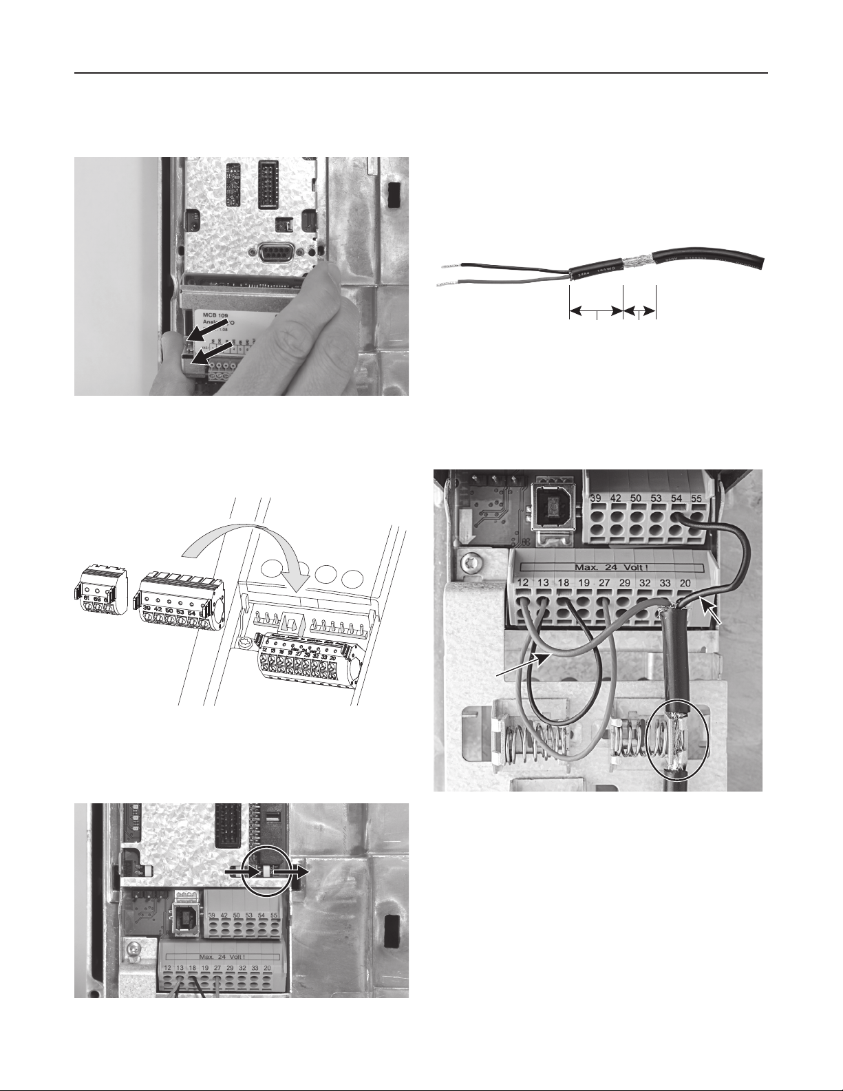
Step 2: Remove the MCB 109 Option Card
Grasp the card and pull straight out from the drive. See
Figure 4.
Figure 4.
Step 3: Install terminal block.
Retrieve the terminal blocks from the Accessory Bag and
install as shown. See Figure 5.
Step 5: Reassemble the components
Put the components back on the drive. To avoid damaging
the option card and keypad, please use care during the
reassembly process.
Prepare Transducer Cable
Remove insulation to expose cable shielding. See Figure 7.
Cut off green wire (if applicable).
1-1/2”
40 mm
Figure 7.
5/8”
16 mm
Wire the Pressure Transducer
The Black wire goes to Terminal 54. The Red wire goes to
Terminal 12. Clamp the bare spot on the cable to ground the
shielding. See Figure 8.
Figure 5.
Step 4: Set A54 dip switch
Using a small screwdriver, move the switch to the right. See
Figure 6.
Figure 6.
Black
wire
Red
wire
Figure 8.
Install Jumper Wires
Install an 18 - 22 AWG Jumper wire between Terminal 13
and Terminal 27. Install a second Jumper wire between
Terminal 13 and Terminal 18. See Figure 8.

Software Setup 3
ATTENTION: Before programming, the system must be able to be primed and then run with a
closed valve to teach the drive about no flow operation.
1
2
English?
Yes
To Next Step
No
OK
Select
language
OK
OK
3
Ag/Irrigation?
Yes
To Next Step
No
OK
Select
OK
Allow 3 to 5 seconds for the drive to configure. Please wait until the screen shows Step 5
before proceeding.
4
OKOK
Move between
characters and
set values
To Next Step

Software Setup 4
5
6
Above
Yes
To Next Step
Select Motor Power
Select Motor Voltage
No
OK
Select
OK
OKOK
OKOK
To Next Step
7
8
Select Motor Current
OKOK
Enter Motor Nominal Current
Select Motor Speed
OKOK
To Next Step
OK
To Next Step

Software Setup 5
9
OK
To Next Step
The next step runs the drive manually. That step
(and the following steps) should be performed with
no flow in the system (i.e. with a closed valve). The
drive is learning about Sleep and Dry Run and to do
this properly, there should not be any flow in the
system – including flow into a pressure tank.
10
Hand
On
O
Ramp up the frequency (motor speed) until
the display indicates 30 Hz. Verify motor
rotation and fill pipes.
With a closed valve, slowly increase the
frequency (motor speed) to 50 Hz. Monitor
pressure on the display during ramp up to
avoid over pressurizing the system. Once
the drive has reached 50 Hz and a safe and
stable pressure, press the OFF button. If the
system over pressurizes before getting to
50 Hz, press OFF button and go to Appendix
A – Manual Sleep Setup to complete the drive
setup.

Software Setup 6
11
12
13
Quick
Menu
OK
To SmartStart
OKOK
Enabled
OK
14
15
Make sure the system is primed and a valve is closed.
Hand
On
 Loading...