

Model PB5RO-75 Undersink Reverse Osmosis System
WARNING:
User Manual
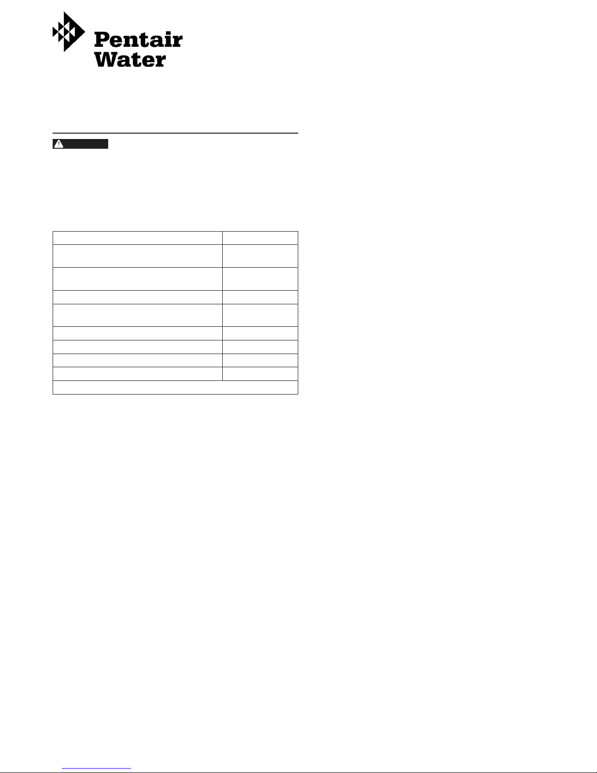
OPERATING SPECIFICATIONS
Before installing the system, make certain
your water supply complies with the
following operating specications. Failure
to do so may reduce the effectiveness
of the system and will void the warranty.
Consult your local water treatment utility or
a certied water testing lab to determine the
quality of your water and use the table below
to record your results for future reference.
PB5RO-75 Specications Your Water
Pressure Range: 40–100 psi
Temperature Range: 40–100°F
Total Dissolved Solids < 2000 ppm
Maximum Hardness* †: 10 gpg
Sulde, Iron and Manganese †: < 0.1
Chlorine in Water Supply: < 2 ppm
Water Supply pH Limits: 3-11
Turbidity: 5 NTU Max.
Date of Purchase:
* If the hardness of your water is above 10 gpg (171 mg/L), lime scale will build
up rapidly on the membrane inside of the RO membrane cartridge. Scale
buildup will plug the RO membrane cartridge and make the system ineffective.
We do not recommend the PB5RO to be used with water in excess of 10 gpg
(171 mg/L) hardness, unless the water is softened prior to the reverse osmosis
system.
†
See your local dealer or water treatment specialist to reduce these substances
in your water.
(2.8–6.9 bar)
(4.4-37.8°C)
(171 mg/L)
PB5RO-75 Dimensions:
System Dimensions 13" H x 18.6" W x 4.75" D
(330 x 3472 x 120.6 mm)
Tank Dimensions 14.5" H x 11" Dia
(368 x 279 mm)
System Weight 29 lbs (10.4 kg)
Tank Capacity 3.2 gal (12.1 L)
Tools Required
• Hand or Electric Drill • Phillips Screwdrivers
• 2 Adjustable Wrenches • Drill Bits: 1/8", 1/4" and 3/8"
• File • Towel
• Pencil • Safety Glasses
• Needle-nose Pliers • Tape Measure
• Utility Knife or Tube Cutter
(for plastic tubing)
Optional Materials
(For sinks without extra hole for faucet)
• Hand or Electric Drill • Center punch
• Drill Bits: 1/4" and 3/4" • Respirator
• Teon® Tape • 1-3/8" Bi-metal or Carbide
Tipped Hole-saw
NOTE: All tools listed will not be necessary for installation.
Read installation procedures before starting to
determine required tools.
Parts Included
• Head Assembly • Drain Saddle Valve
• Screws for mounting • Water Supply Adapter
• Lead-free air gap drinking
• Quick-connect Fitting
water faucet
• Silicone grease • Storage Tank
• Tank Valve • Faucet Adapter
• Teon® Tape • Change Indication Sticker
• 3/8" Plastic Tubing
(red and blue)
• 1/4" Plastic Tubing
(white, red and green)
• TDS Test Kit
• Filter Cartridges:
PW-S2500R Cartridge Yellow
PW-C5000R Cartridge Blue
PW-RO75R Cartridge Green
PW-C2500R Cartridge Violet
247181 Rev D JA12

GENERAL PRECAUTIONS
WARNING:
WARNING:
WARNING:
WARNING:
CAUTION
CAUTION
Do not use with water that is
microbiologically unsafe or of unknown
quality without adequate disinfection before
or after the system. Systems certied for
cyst reduction may be used on disinfected
waters that may contain lterable cysts.
The PB5RO contains a replaceable RO
membrane cartridge that is critical to the
efciency of the system. Replacement of the
RO membrane cartridge should be with one
of identical specications, as dened by the
manufacturer, to assure the same efciency
and contaminant reduction performance.
The PB5RO contains a replaceable RO
membrane cartridge, critical for the effective
reduction of total dissolved solids. Product
water should be tested periodically to verify
that the system is working properly.
The PB5RO is acceptable for treatment
of inuent concentrations of no more
than 27 mg/L nitrate and 3 mg/L nitrite in
combination measured as N and is certied
for nitrate/nitrite reduction only for water
supplies with a pressure of 40 psig (280 kPa)
or greater.
WARNING:
WARNING:
CAUTION
NOTE: Substances listed as reduced are not necessarily
NOTE: Your water must be within required limits for
NOTE: Install on cold water line only.
NOTE: Do not install where system will be exposed to
NOTE: Make certain that installation complies with all state
NOTE: The lter cartridges and RO membrane cartridge
NOTE: During extended periods of non-use (such as
The PB5RO shall only be used for arsenic
reduction on chlorinated water supplies
containing detectable residual free chlorine
at the system inlet. Water systems using an
in-line chlorinator should provide a one-
minute chlorine contact time before the unit.
The PB5RO will not protect against disease-
causing bacteria or remove naturallyoccurring harmless bacteria.
The PB5RO must be protected against freezing
which can cause the lter housing to crack,
resulting in water leakage.
Turn off water supply to head without cartridge if
it must be left unattended for an extended period
of time.
Do not use electrical heating tape on this unit.
in your water. System must be maintained
according to manufacturer's instructions, including
replacement of lter cartridges.
satisfactory operation. If not, the RO membrane
cartridge’s life may be shortened and your warranty
will be voided (see Operating Specications).
direct sunlight.
and local laws and regulations.
included with the system have limited service lives.
Changes in taste, odor, and color of the ltered
water indicate that the cartridges and/or membrane
should be replaced.
during a vacation), remove the membrane cartridge
and the lter cartridges from the unit and place
them in a sealed plastic bag. Store the cartridges
in the refrigerator for future use. When re-starting
the unit, replace all cartridges and ush per
instructions.
NOTE: If the PB5RO stands for more than 2 to 3 days
without being used, the storage tank should be
emptied.
NOTE: Use only Teon® tape without adhesive backing
to seal joints. Do not use pipe compound (“pipe
dope”), sticks, or similar compounds with this
unit; they contain petroleum derivatives which can
cause crazing and cracking of the plastic in the
lter housing.
NOTE: Use only soap and water to clean components.
NOTE: Do not use aerosol sprays (bug spray, cleaning
uids, etc.) near the PB5RO. They contain organic
solvents which will cause crazing and cracking of
the plastic in the lter housing.
NOTE: After prolonged periods of non-use, such as a
vacation, it is recommended that the system be
ushed thoroughly. Let water run for 2 to 3 minutes
before using.
NOTE: Do not use a torch near the unit.
HOW REVERSE OSMOSIS (RO) WORKS
The PB5RO uses a semi-permeable membrane to reduce
dissolved salts, improving the taste and odor of your water. The
RO membrane cartridge contains multiple layers of micron-thin
lm wound around a hollow center core. Water molecules can
pass through the cartridge, while dissolved salts are rejected.
Your household water supply is pre-ltered to reduce dirt and
chlorine that may foul the membrane. The RO membrane
cartridge separates this pre-ltered water into PRODUCT
WATER and REJECT WATER. Your household water pressure
forces water through the membrane within the RO membrane
cartridge, and into the storage tank. This is product water.
Dissolved salts cannot pass through the membrane and are
sent to the drain as reject water. When you open the faucet,
product water (permeate) is drawn from the storage tank
through a post-polishing lter. The post-polishing lter takes out
any remaining taste or odor in the water and provides you and
your family with cleaner, great-tasting water.
The PB5RO also features an auto shut-off valve, which shuts
off the system once the pressure in the storage tank reaches
2/3 of the incoming water pressure (your household water
pressure). When you open the faucet to draw water from
the storage tank, the pressure inside the tank drops and
the auto shut-off valve opens. The system then begins to
operate, replenishing the water you took from the storage tank.
Depending on the system's efciency, for each gallon of water
produced, up to 7 gallons are discharged as reject water. The
storage tank can hold up to 3.2 gallons (12.1 L) of water at a
time, more than enough for the average family’s drinking and
cooking needs.
NOTE: When used under operating conditions specied
on page 1 of this manual, the RO membrane
cartridge of the PB5RO should last 12–24 months.
The precise life span of the PB5RO's RO membrane
cartridge will depend on the quality of the water
entering the system, and the frequency with which
you use it. Frequent use prevents the dissolved
salts from building up on the membrane as scale.
The more water the system is required to produce,
the longer the membrane will last. You may wish
to nd a variety of uses for your PB5RO system in
order to prolong the life of the membrane.
2 • JA12 Model PB5RO-75 Undersink Reverse Osmosis System

INSTALLATION
WARNING:
WARNING:
WARNING:
WARNING:
NOTE: Please read all instructions, specications, and
precautions before installing and using your
PB5RO system.
NOTE: The PB5RO may be installed under a sink or in the
basement.
NOTE: The PB5RO is installed vertically.
NOTE: Numbered diagrams correspond with numbered
steps.
NOTE: For standard installation on 1/2" 14 NPS threads
(most common thread on kitchen faucets) cold
water line.
1. Installing the Water Supply Adapter
The supply adapter ts 1/2" 14 NPS supply threads. If local
codes permit, it may be used to connect the lter system
to the cold water supply line. If local codes do not permit
the use of the supply adapter, alternate connectors can be
obtained from your local retailer.
A. Turn off cold water supply line. If cold water line does
not have a shut-off valve under the sink, one should be
installed.
B. Turn on the cold water faucet and allow all water to
drain from line.
C. Disconnect cold water line from 1/2" 14 NPS threaded
stub on bottom of main faucet.
D. Screw the water supply adapter to the threaded faucet
stub as shown.
E. Using the nut that previously connected the cold water
line to the faucet, screw the cold water line to the male
supply adapter threads.
E
C
B
2. Selecting the Faucet Location
NOTE: The drinking water faucet should be positioned
with function, convenience, and appearance in
mind. An adequate at area is required to allow
faucet base to rest securely. The faucet ts through
a 1-3/8" hole. Most sinks have pre-drilled 1-3/8" or
1-1⁄2" diameter holes that may be used for faucet
installation. If these pre-drilled holes cannot be
used or are in an inconvenient location, it will
be necessary to drill a 1-3/8" hole in the sink to
accommodate the faucet.
This procedure may generate dust which
can cause severe irritation if inhaled or come
in contact with the eyes. The use of safety
glasses and respirator for this procedure is
recommended.
Do not attempt to drill through an all-
porcelain sink. If you have an all-porcelain
sink, mount the faucet in pre-drilled sprayer
hole or drill through countertop next to sink.
When drilling through a countertop, make
sure the area below the drilled area is free
of wiring and piping. Make certain that
you have ample room to make the proper
connections to the bottom of the faucet.
Do not drill through a countertop that is
more than 1" thick.
WARNING:
A. Line bottom of sink with newspaper to prevent metal
B. Place masking tape over the area to be drilled to help
C. Mark hole with center punch. Use a 1/4" drill bit for a
D. Using a 1-3/8" hole saw, drill a hole completely through
Do not attempt to drill through a tiled,
marble, granite or similar countertop.
Consult a plumber or the countertop
manufacturer for advice or assistance.
shavings, parts, or tools from falling down drain.
prevent scratches if drill bit slips.
pilot hole.
the sink. Smooth the rough edges with a le.
F
D
A
Figure 1
C
C
1
4”
D
11⁄4”
D
Model PB5RO-75 Undersink Reverse Osmosis System JA12 • 3
⁄
Figure 2
B
A
INSTALLATION contin ued
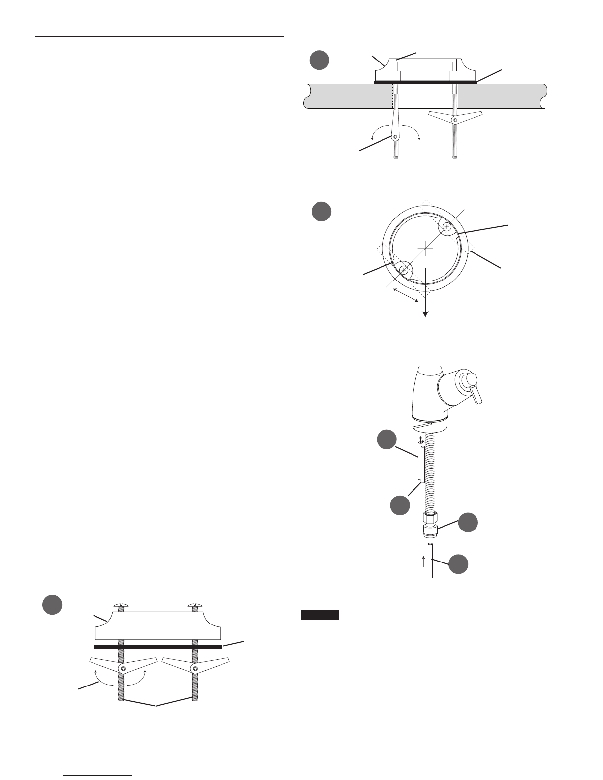
3. Mounting the Faucet
A. Pre-assemble the base. The rubber washer should be
in place below the base. The two toggle bolts should be
inserted through the base and the rubber washer. The
bolts are screwed into the spring-loaded toggle.
B. Place the base assembly over the hole in the sink. The
two toggles should pass through the hole far enough to
spring fully open. If they are not open, unscrew the bolt
until the toggle moves down to clear the sink.
C. Look down through the base for this step. Before
tightening the bolts, determine the correct rotation of the
base. The nal position of the handle will be 45 degrees
off from the bolt heads. Use Figure 5 to help determine
the best position for your installation.
Through the hole in the base, hold the toggle in position
while tightening the bolt. The spring loaded toggle
will contact the bottom of the counter top and hold in
position. Do not fully tighten. Repeat for second toggle
bolt.
Check the nal position of the base and toggle bolts.
Tighten the two bolts evenly. DO NOT OVERTIGHTEN.
Tighten only far enough to prevent the base from
rotating when the faucet is rotated in place.
D. Attach large diameter 3/8" (red) drain tube to the larger
barb tting at the faucet bottom. This tube should be
long enough to reach the drain clamp in Step 7.
E. Locate the 1/4" red brine tube from the right side of the
system head assembly. Route the tube through the
faucet base and connect to small barb on the faucet.
Make certain that the tube is not kinked or stressed
once the head assembly is mounted.
F. Apply 3-5 wraps of Teon tape to faucet stem. Screw
quick connector onto end of threads.
G. Wet end of 3/8" blue tube. Push into bottom of
connector. Tug gently to be sure connection is
complete. This tube should be long enough to reach the
top right side of the RO Assembly.
H. Check that the O-ring is in place on the faucet. Feed
the remaining 3/8" tubes through the base. Hold the
faucet in the nal position and rotate backwards (to the
left) while pushing down. The faucet will drop into the
base. Push down on the faucet and rotate forward (to
the right) to lock it into nal position. The O-ring will be
seated and the faucet held securely in position.
I. Insert the spout into the top opening. Hold in position
and screw the collar onto the base.
NOTE: If the faucet handle is not in the correct
position, remove the faucet, loosen the toggle
bolts and reposition the base. Tighten the
toggle bolts. Then reinstall the faucet.
Base
B
Will Spring Open
C
Notch For Faucet
Handle Faces This Direction
D
Figure 4
45°
Figure 5
E
Figure 6
O-ring Seat
G
Black Rubber
Washer
Notch For Faucet
Blades Must Be Held
When Tightening
F
A
Folds Upward
4 • JA12 Model PB5RO-75 Undersink Reverse Osmosis System
Base
Figure 3
Black Rubber
Washer
4. Mounting the System
CAUTION
The lter head assembly should be mounted on
a stud or rm surface. The mounting bracket will
support the weight of the cartridges and help
prevent strain on the water lines.
A. Select location under sink or in basement where unit
is to be mounted. The head assembly is mounted in a
vertical position.
B. When mounting the PB5RO-75 the top of the head
must be 15-1/2" above the nearest obstacle (oor of the
cabinet). Two screws are supplied to mount the head.
Measure up from the oor of the cabinet 14-1/2". The
two screws will be 17.7" apart and level. Screw the two
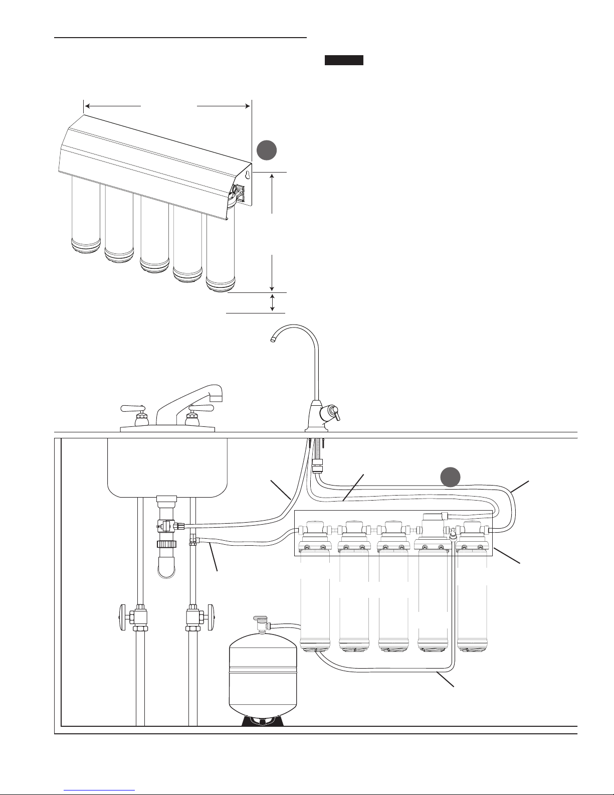
INSTALLATION contin ued
CAUTION
screws into the wall. Leave a gap between the screw
head and the wall of 1/8". The backside of the system
head has two slots that will t over the screw heads and
slide down to lock.
17.7 Inches
Between Holes
2-1/2 Inches Clearance Below Cartridges
B
12 Inches
From Mounting
Hole to Bottom
of Cartridge
5. Connecting the Faucet
Water supply to the tee should have a separate
shut-off valve. If it does not, a separate shut-off
should be installed.
A. Locate the 3/8" blue tubing from the faucet and place a
mark 5/8" from the end of the tubing. Moisten the end of
the tubing with water and insert into the quick-connect
tting on the head assembly until the mark is ush with
the quick-connect tting.
B. Gently pull back on the tubing to ensure it is connected
properly. If the tubing comes out of tting, cut a small
section off of the tubing and reconnect.
NOTE: Tubing may be quickly and easily removed from
the tting if necessary. First, turn off the water
supply to the lter. Open faucet, then press in
the collet around the tting while pulling the
tubing with your other hand.
Figure 7
Step 6
Step 8
3/8" Red
1/4" White
PW-S2500R
Yellow
Step 9
PW-C5000R
Blue
PW-C5000R
Blue
1/4" Red
PW-RO75R
Green
3/8" Blue
A
PW-C2500R
Violet
Step 5
Cover Not Shown
1/4" Green
Step 11
Figure 8
Model PB5RO-75 Undersink Reverse Osmosis System JA12 • 5
 Loading...